s power 45 180s technical specification v00 en · 2016-11-30 ·...
TRANSCRIPT

HITZINGER GmbH | 4021 Linz | Austria | Helmholtzstraße 56 | Postfach 5000 | T +43 732 381681-0 | F -4 | www.hitzinger.at
TECHNICAL SPECIFICATION
S POWER 45 to 180S Solid State Ground Power Unit
HITZINGER GmbH | 4021 Linz | Austria | Helmholtzstraße 56 | Postfach 5000 | T +43 732 381681-222 | F -4222 | www.hitzinger.at

S POWER 45-180S | Technical specification
\\kb\Produkte\6_Flughafen\S_POWER\01_Verkauf_Marketing\03_Texte\02_Technische_Spezifikation\01_SPOWER30_180S\01_Englisch\S_POWER_45_180S_technical_specification_V00_en.doc
Edition 01 - Page 2 / 30
HITZINGER S POWER 45 to 180kVA
1 General information about HITZINGER............................................................... 4 1.1 General / History..........................................................................................................4 1.2 Products .....................................................................................................................5
1.2.1 Alternators...................................................................................................6 1.2.2 Airport Ground Power Systems .......................................................................6
1.2.2.1 Diesel Driven Ground Power Supply D POWER .............................................6 1.2.2.1.1 D POWER.........................................................................................6 1.2.2.1.2 JET POWER......................................................................................6
1.2.2.2 Centralized rotary frequency converters R POWER........................................6 1.2.2.3 Decentralized rotary frequency converters R POWER ....................................7 1.2.2.4 Solid State Ground Power Unit S POWER ....................................................7
1.2.3 Converters...................................................................................................7 1.2.4 Diesel Generators .........................................................................................8 1.2.5 Dynamic Diesel UPS ......................................................................................8
2 Product description ............................................................................................ 9 2.1 Advantages of Hitzinger S POWER ................................................................................ 10 2.2 S POWER – General information ................................................................................... 11
2.2.1 Product key................................................................................................ 11 2.2.2 Applications ............................................................................................... 11 2.2.3 Power range............................................................................................... 11 2.2.4 Options ..................................................................................................... 11 2.2.5 Standards.................................................................................................. 11 2.2.6 Finish........................................................................................................ 12
2.3 Technical Data ........................................................................................................... 13 2.3.1 Technical Data S POWER 45 - 180kVA ........................................................... 13
2.3.1.1 General Technical Data........................................................................... 13 2.3.1.2 Input:.................................................................................................. 13 2.3.1.3 Output:................................................................................................ 14 2.3.1.4 Standards: ........................................................................................... 14
2.3.2 Dimension diagram S POWER ....................................................................... 15
3 Function of S POWER........................................................................................ 16 3.1 General Discription ..................................................................................................... 16 3.2 The stack technology .................................................................................................. 16 3.3 Functional description of 45kVA stack............................................................................ 17
4 Main components.............................................................................................. 18 4.1 POWER Stack............................................................................................................. 18
4.1.1 Internal Stack system ................................................................................. 18 4.1.2 Active Power Factor Correction (PFC) – active rectification (AC/DC).................... 18 4.1.3 Intermediate circuit capacitors...................................................................... 19 4.1.4 DC / AC inverter ......................................................................................... 19 4.1.5 Baseboard ................................................................................................. 19 4.1.6 Modular Stack design .................................................................................. 19 4.1.7 400Hz-Transformer ..................................................................................... 19
4.2 Housing .................................................................................................................... 20 4.3 Switch panel.............................................................................................................. 21
4.3.1 400 Hz switch panel .................................................................................... 21 4.3.1.1 Main components of the 400 Hz switch panel............................................. 22
4.3.2 Service panel ............................................................................................. 22 4.3.3 28 VDC Unit (optional) ................................................................................ 23

S POWER 45-180S | Technical specification
\\kb\Produkte\6_Flughafen\S_POWER\01_Verkauf_Marketing\03_Texte\02_Technische_Spezifikation\01_SPOWER30_180S\01_Englisch\S_POWER_45_180S_technical_specification_V00_en.doc
Edition 01 - Page 3 / 30
4.3.3.1 General................................................................................................ 23 4.3.3.2 Function............................................................................................... 23 4.3.3.3 Current limitation (optional).................................................................... 23
4.4 Control panel with HITZINGER ACON microprocessor control unit ...................................... 23 4.4.1 General ..................................................................................................... 23 4.4.2 HITZINGER ACON ....................................................................................... 24
4.4.2.1 Overview ACON modules ........................................................................ 25 4.4.2.2 Measuring values - indication on the touch display ..................................... 25 4.4.2.3 Operation indications ............................................................................. 25 4.4.2.4 Failure indications.................................................................................. 25 4.4.2.5 Switches and push buttons ..................................................................... 26
4.5 Operation panel ......................................................................................................... 27 4.6 Installation ................................................................................................................ 28
4.6.1 Fixing........................................................................................................ 29
5 Contact ............................................................................................................. 30 5.1 Sales department ....................................................................................................... 30 5.2 Service department .................................................................................................... 30

S POWER 45-180S | Technical specification
\\kb\Produkte\6_Flughafen\S_POWER\01_Verkauf_Marketing\03_Texte\02_Technische_Spezifikation\01_SPOWER30_180S\01_Englisch\S_POWER_45_180S_technical_specification_V00_en.doc
Edition 01 - Page 4 / 30
1 General information about HITZINGER
1.1 General / History Mr. Dipl. Ing. Hitzinger founded the Dipl. Ing. Hitzinger KG on 1. January 1946 in Linz / Austria in the heart of Europe.
Figure 1: Geographische Lage
Today HITZINGER is an independent, privately owned company with an extensive experi-ence in providing tailored high quality turnkey power solutions. For this reason HITZINGER is a competent and reliable partner for all kinds of electrical power supplies!
Figure 2: Hitzinger today
S POWER 45-180S | Technical specification
\\kb\Produkte\6_Flughafen\S_POWER\01_Verkauf_Marketing\03_Texte\02_Technische_Spezifikation\01_SPOWER30_180S\01_Englisch\S_POWER_45_180S_technical_specification_V00_en.doc
Edition 01 - Page 5 / 30
Over 60 years
Technology Quality Reliability Efficiency Cost effectiveness Support
has driven our development !
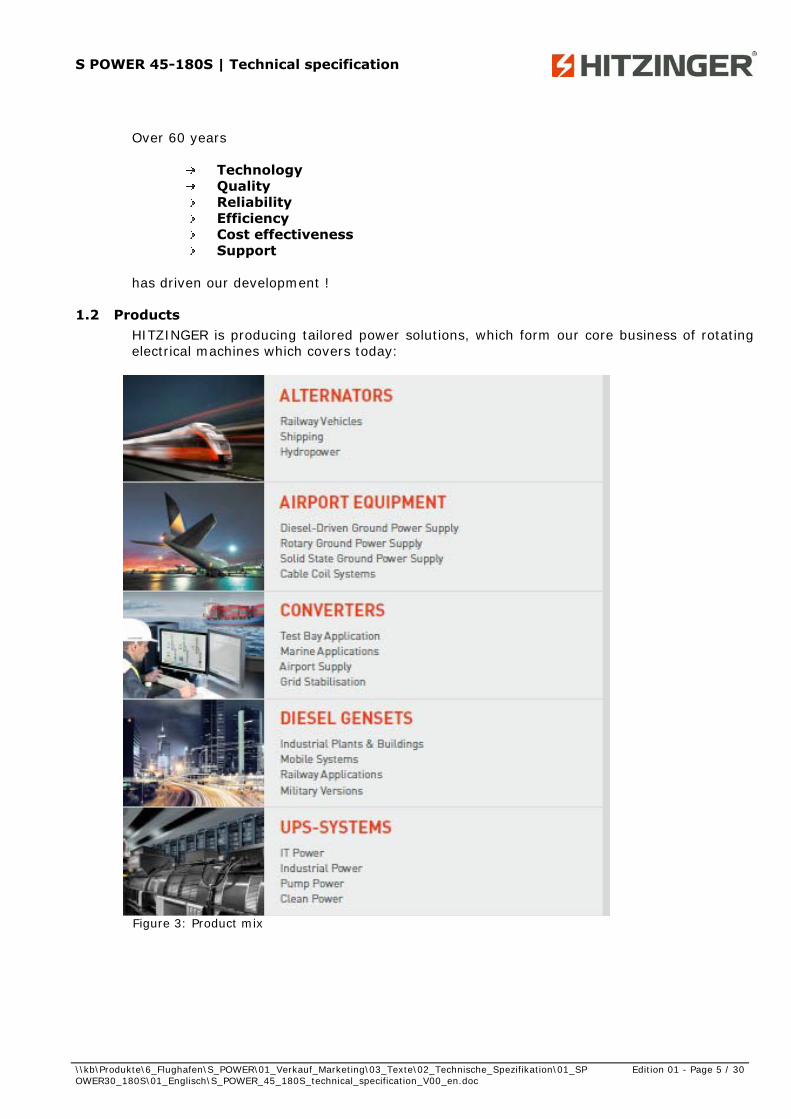
1.2 Products HITZINGER is producing tailored power solutions, which form our core business of rotating electrical machines which covers today:
Figure 3: Product mix

S POWER 45-180S | Technical specification
\\kb\Produkte\6_Flughafen\S_POWER\01_Verkauf_Marketing\03_Texte\02_Technische_Spezifikation\01_SPOWER30_180S\01_Englisch\S_POWER_45_180S_technical_specification_V00_en.doc
Edition 01 - Page 6 / 30
1.2.1 Alternators
HITZINGER synchronous machines offer the highest technical standard & quality with the flexibility to provide tailor-made solutions. 10 kVA – 4 MVA, DC – 11 kV, 2 – 28 pole for ap-plications including industrial, marine & off shore, hydropower, low magnetic signature etc. designed for all environments and the most arduous of loads. HITZINGER alternators guar-antee an individual power supply and a highly efficient, reliable and economic solution.
1.2.2 Airport Ground Power Systems
1.2.2.1 Diesel Driven Ground Power Supply D POWER
1.2.2.1.1 D POWER
HITZINGER provides the latest design in diesel driven ground power unit operating in ex-treme ambient conditions with the lowest environmental emissions:
Power range from 90 - 180kVA Up to 50% lower service and maintenance costs Up to 25% lower fuel consumption Extremely low sound level (<68dBA) High reliability & availability
1.2.2.1.2 JET POWER
With the JET POWER, Hitzinger is presenting a new quality of ground power supply in the flight preparation phase, especially for small aircrafts and in the general aviation sector.
Power range 30 / 45 / 60kVA Towed model Up to 50% lower service and maintenance costs Up to 25% lower fuel consumption Extremely low sound level (<68dBA) High reliability & availability
1.2.2.2 Centralized rotary frequency converters R POWER
HITZINGER has an international reputation for quality, reliability, design and experience on 400Hz systems which have been installed in many international renowned Airports including Airbus (Toulouse), London Stansted, Vienna, Roma and Frankfurt to name a few.
HITZINGER have proven solutions for fixed rotary 400Hz installations with system outputs up to 2500kVA with all the necessary features including:
Data links for remote monitoring Automatic billing systems Line Drop Compensation Failure recorder
S POWER 45-180S | Technical specification
\\kb\Produkte\6_Flughafen\S_POWER\01_Verkauf_Marketing\03_Texte\02_Technische_Spezifikation\01_SPOWER30_180S\01_Englisch\S_POWER_45_180S_technical_specification_V00_en.doc
Edition 01 - Page 7 / 30
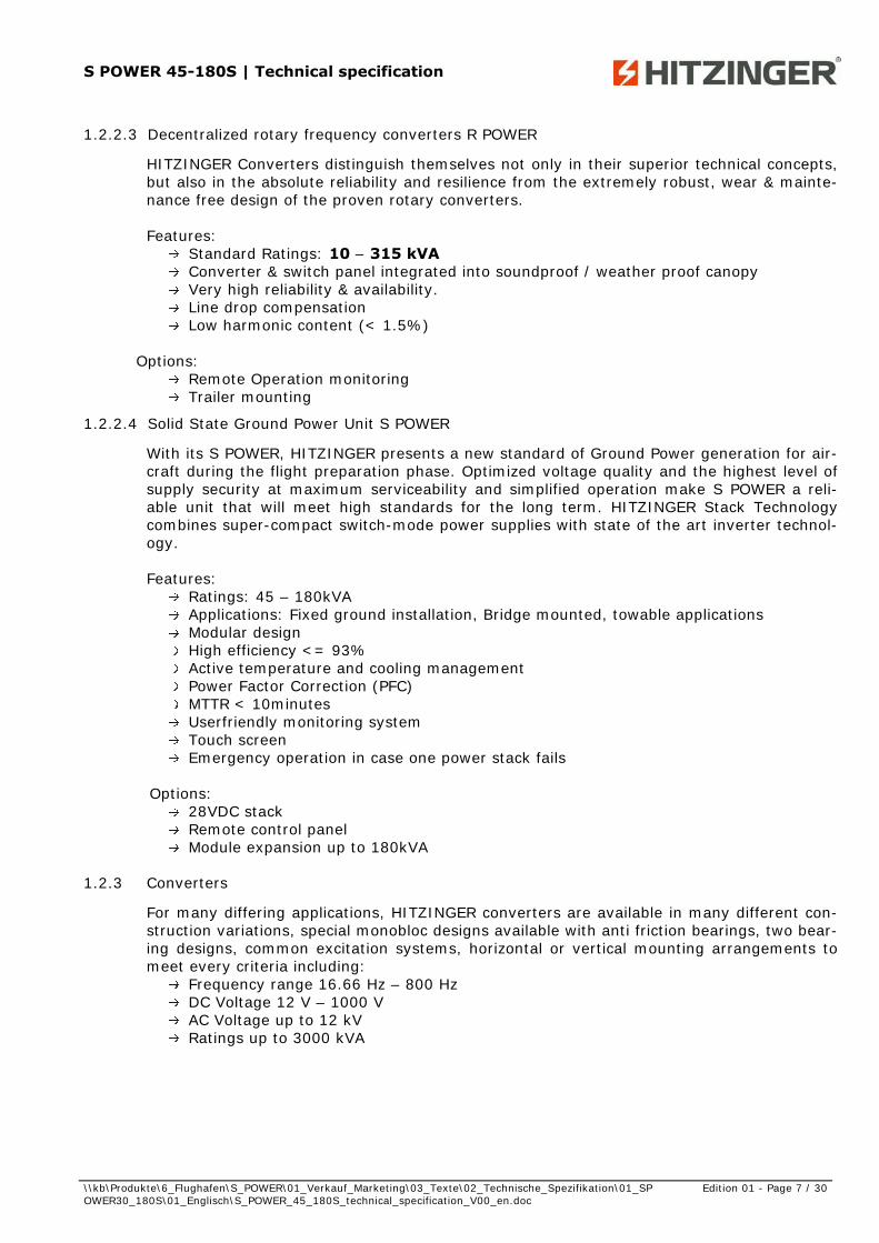
1.2.2.3 Decentralized rotary frequency converters R POWER
HITZINGER Converters distinguish themselves not only in their superior technical concepts, but also in the absolute reliability and resilience from the extremely robust, wear & mainte-nance free design of the proven rotary converters. Features:
Standard Ratings: 10 – 315 kVA Converter & switch panel integrated into soundproof / weather proof canopy Very high reliability & availability. Line drop compensation Low harmonic content (< 1.5%)
Options:
Remote Operation monitoring Trailer mounting
1.2.2.4 Solid State Ground Power Unit S POWER
With its S POWER, HITZINGER presents a new standard of Ground Power generation for air-craft during the flight preparation phase. Optimized voltage quality and the highest level of supply security at maximum serviceability and simplified operation make S POWER a reli-able unit that will meet high standards for the long term. HITZINGER Stack Technology combines super-compact switch-mode power supplies with state of the art inverter technol-ogy.
Features:
Ratings: 45 – 180kVA Applications: Fixed ground installation, Bridge mounted, towable applications Modular design High efficiency <= 93% Active temperature and cooling management Power Factor Correction (PFC) MTTR < 10minutes Userfriendly monitoring system Touch screen Emergency operation in case one power stack fails
Options:
28VDC stack Remote control panel Module expansion up to 180kVA
1.2.3 Converters
For many differing applications, HITZINGER converters are available in many different con-struction variations, special monobloc designs available with anti friction bearings, two bear-ing designs, common excitation systems, horizontal or vertical mounting arrangements to meet every criteria including:
Frequency range 16.66 Hz – 800 Hz DC Voltage 12 V – 1000 V AC Voltage up to 12 kV Ratings up to 3000 kVA

S POWER 45-180S | Technical specification
\\kb\Produkte\6_Flughafen\S_POWER\01_Verkauf_Marketing\03_Texte\02_Technische_Spezifikation\01_SPOWER30_180S\01_Englisch\S_POWER_45_180S_technical_specification_V00_en.doc
Edition 01 - Page 8 / 30
1.2.4 Diesel Generators
As specialists, we provide solutions from design to installation and beyond with a wealth of experience to assure a competitive cost completed on programme.We are able to provide the highest quality power for continuous and emergency loads including specialist applica-tions requiring tailored solutions and systems to reduce exhaust emissions, sound levels, shock and vibration, EMC and dimensions and weight. Basic Version: Skid mounted for stationary installation Portable Version: with weatherproof canopy for indoor & outdoor installation
(optional noise suppression levels) Containerised Version: mounted in ISO standard containers
(optional noise suppression levels) Mobile Version: mounted on single or twin axle trailers with individual tailored
options available.
Diesel powered sets Rating 10 – 3000 kVA Voltage up to 11 kV Frequencies 50 – 400 Hz
1.2.5 Dynamic Diesel UPS
Two DDUPS Systems are available: 1) Computer Grade Power - NBDK DDUPS System with Kinetic Energy Storage Module for frequency accuracy < 1 % 2) Industrial Power - NBDD DDUPS System with a frequency deviation < 5 % These systems provide extremely high availability and total reliability in case of mains failure and high efficiency during stand-by operation. The reliability of HITZINGER DDUPS systems is the result of a product philosophy using a minimum number of system components having an optimum quality standard. Features:
Ratings: up to 2500 kVA Voltage: up to 11 kV (without step-up Transformer) Dual output units MTBF value: > 1M hours Availability: > 99,9999 % Low MTTR value Low maintenance costs High choke quality High overload capacity Efficiency up to 97% Power factor improvement Optimum mains failure supervision In house developed control system Brushless design, no slip rings
An absolute reliable and uninterrupted close tolerance power solution for today’s mission critical processes.
S POWER 45-180S | Technical specification
\\kb\Produkte\6_Flughafen\S_POWER\01_Verkauf_Marketing\03_Texte\02_Technische_Spezifikation\01_SPOWER30_180S\01_Englisch\S_POWER_45_180S_technical_specification_V00_en.doc
Edition 01 - Page 9 / 30
2 Product description Hitzinger presents with its S POWER a new standard of ground power generation for all air-crafts during the flight preparation phase. Optimized voltage quality and the highest level of supply security at maximum serviceability and simplified operation make S POWER a reli-able unit that will meet high standards for the long term. The Hitzinger S POWER Stack Technology combines active power factor correction with state of the art inverter technol-ogy. The intelligent distribution of the individual stacks and the configuration of the S POWER guarantees very high efficiency during turn-down for all load requirements. The formal principle of existing facilities has been redesigned in terms of installation, main-tenance and service. The dynamic style reflects innovation and technological know-how and gives the product its very modern look. The access area at the front is spacious and ergo-nomically optimized for service personnel. The design is based on the rules of the light-weight construction and use of aluminium for and frame with ABS fairing kit. The column design is- in the sense of modularity – still conventional. From the installation to the first start and permanent application, S POWER sets itself apart with its reliability and its simple operation. Optimal voltage quality at maximum service se-curity and serviceability guarantee power. The intelligent distribution of the individual stacks and the configuration of the S POWER guarantees maximum efficiency during turn-down for all load requirements. The stack technology enables individual stacks to be easily serviced. In case a stack fails, redundant operation is possible. Remote maintenance enables every important operational state to be displayed and param-eterized for quick and easy serviceability. An active temperature monitoring and cooling management, via regulation of ventilation, guarantee power even in extreme ambient tem-peratures. Exact error notification shortens maintenance periods and optimizes service. The touch panel on the controller features intuitive user guidance. The display is easy to read in sunny conditions, it is dust and waterproof, and it is suitable fort he most adverse airfield conditions. It may even be operated by gloved hands.
S POWER 45-180S | Technical specification
\\kb\Produkte\6_Flughafen\S_POWER\01_Verkauf_Marketing\03_Texte\02_Technische_Spezifikation\01_SPOWER30_180S\01_Englisch\S_POWER_45_180S_technical_specification_V00_en.doc
Edition 01 - Page 10 / 30
2.1 Advantages of Hitzinger S POWER
Highest efficiency ≥ 93%
Power Factor Correction (PFC),power factor= 0,99
Optimal compensation of the voltage drop
Modular and compatible POWER Stacks
Active temperature / cooling management
Redundant operation is possible in case of one POWER Stack fails
Precise synchronization of individual POWER Stacks
Lowest weight
Serviceable Stacks
Innovative Touch-technology
Exact load calculation
Maintenance friendly via remote diagnosis and self-diagnosis
MTTR < 10min
Comfortable maintenance and parameter settings
Mains voltage-/frequency-fluctuations have no impact on the quality
of the output voltage
3-Level inverter technology
Stack protection IP66
S POWER 45-180S | Technical specification
\\kb\Produkte\6_Flughafen\S_POWER\01_Verkauf_Marketing\03_Texte\02_Technische_Spezifikation\01_SPOWER30_180S\01_Englisch\S_POWER_45_180S_technical_specification_V00_en.doc
Edition 01 - Page 11 / 30
2.2 S POWER – General information
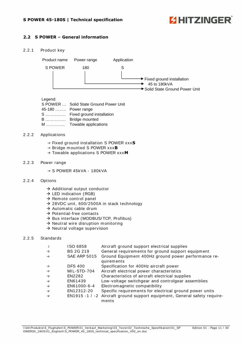
2.2.1 Product key
Product name Power range Application
S POWER 180 S
Fixed ground installation45 to 180kVA
Solid State Ground Power Unit
Legend:S POWER … Solid State Ground Power Unit45-180 …….. Power rangeS …………… Fixed ground installationB …………… Bridge mountedM ………….. Towable applications
2.2.2 Applications
Fixed ground installation S POWER xxxS Bridge mounted S POWER xxxB Towable applications S POWER xxxM
2.2.3 Power range
S POWER 45kVA - 180kVA
2.2.4 Options
Additional output conductor LED indication (RGB) Remote control panel 28VDC unit, 600/2500A in stack technology Automatic cable drum Potential-free contacts Bus interface (MODBUS/TCP, Profibus) Neutral wire disruption monitoring Neutral voltage supervision
2.2.5 Standards
ISO 6858 Aircraft ground support electrical supplies BS 2G 219 General requirements for ground support equipment SAE ARP 5015 Ground Equipment 400Hz ground power performance re-
quirements DFS 400 Specification for 400Hz aircraft power MIL-STD-704 Aircraft electrical power characteristics EN2282 Characteristics of aircraft electrical supplies EN61439 Low-voltage switchgear and controlgear assemblies EN61000-6-4 Electromagnetic compatibility EN12312-20 Specific requirements for electrical ground power units EN1915 -1 / -2 Aircraft ground support equipment, General safety require-
ments
S POWER 45-180S | Technical specification
\\kb\Produkte\6_Flughafen\S_POWER\01_Verkauf_Marketing\03_Texte\02_Technische_Spezifikation\01_SPOWER30_180S\01_Englisch\S_POWER_45_180S_technical_specification_V00_en.doc
Edition 01 - Page 12 / 30
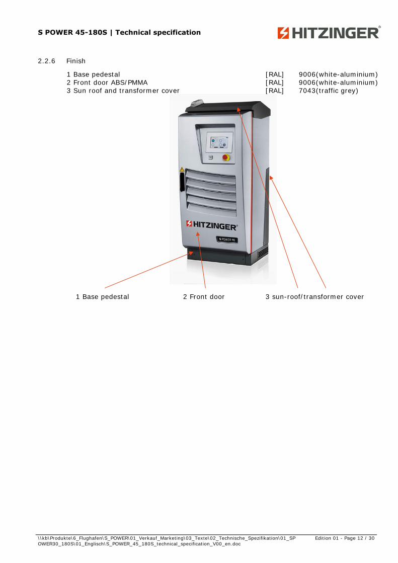
2.2.6 Finish
1 Base pedestal [RAL] 9006(white-aluminium) 2 Front door ABS/PMMA [RAL] 9006(white-aluminium) 3 Sun roof and transformer cover [RAL] 7043(traffic grey)
1 Base pedestal 2 Front door 3 sun-roof/transformer cover

S POWER 45-180S | Technical specification
\\kb\Produkte\6_Flughafen\S_POWER\01_Verkauf_Marketing\03_Texte\02_Technische_Spezifikation\01_SPOWER30_180S\01_Englisch\S_POWER_45_180S_technical_specification_V00_en.doc
Edition 01 - Page 13 / 30
2.3 Technical Data
2.3.1 Technical Data S POWER 45 - 180kVA
2.3.1.1 General Technical Data
Protection system:
Protection class:
Ambient temperature: °C
Humidity: %
max. sea level: m
Noise level (at 1m, height 1,8m): d(bA)
Dimensions (Width x Height x Depth) incl. plinth (100mm):
S POWER 45 S POWER 90 S POWER 180
Fixed ground installation: 600 x 1396 x 716 600 x 1396 x 716 1200 x 1396 x 716 mm
Weight: 240 285 550 kg
Bridge mounted: 850 x 850 x 900 850 x 850 x 900 1700 x 850 x 900 mm
Weight: 310 350 700 kg
Mobile version: - - - mm
Weight: - - - kg
Weight S POWER Stack: 40 kg
Losses
standby losses 25 W
no-load losses 1300 W
28VDC output continuous / peak load: A
Standards:
Technical data
TN / (Option IT)
IP55
600/2500
DIN ISO 6858, EN2282, EN1915-1, EN1915-2, EN12312-20, EN61439, SAE ARP 5015, DFS400, BS 2G 219, MIL-STD-704
-30 …+52
95
1000
65
2.3.1.2 Input: Type: S POWER 45 S POWER 90 S POWER 180
Input
Voltage range *: 3 x 400 ±10% V
3 x 480 ±10% V
Frequency: 50/60 ±5% Hz
Powerfactor: 0,99 with PFC (Power Factor Correction)
Distortion factor: < 5 %
Inrush current: none, (< In)
Nominal current (@400V, PF=1): 70 140 279 A
Nominal current (@480V, PF=1): 58 116 233 A
Nominal current (@400V, PF=0.8): 56 112 223 A
Nominal current (@480V, PF=0.8): 47 93 186 A
S POWER 45-180S | Technical specification
\\kb\Produkte\6_Flughafen\S_POWER\01_Verkauf_Marketing\03_Texte\02_Technische_Spezifikation\01_SPOWER30_180S\01_Englisch\S_POWER_45_180S_technical_specification_V00_en.doc
Edition 01 - Page 14 / 30
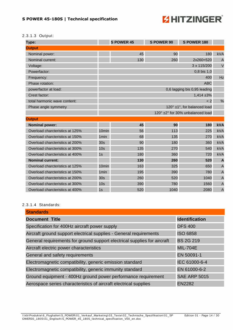
2.3.1.3 Output: Type: S POWER 45 S POWER 90 S POWER 180
Nominal power: 45 90 180 kVA
Nominal current: 130 260 2x260=520 A
Voltage: V
Powerfactor:
Frequency: Hz
Phase rotation:
powerfactor at load: 0,6 lagging bis 0,95 leading
Crest factor: 1,414 ±3%
total harmonic wave content: < 2 %
Phase angle symmetry 120° ±1°, for balanced load
120° ±2° for 30% unbalanced load
ABC
Output
3 x 115/200
0,8 bis 1,0
400
Nominal power: 45 90 180 kVA
Overload charcteristics at 125% 10min 56 113 225 kVA
Overload charcteristics at 150% 1min 68 135 270 kVA
Overload charcteristics at 200% 30s 90 180 360 kVA
Overload charcteristics at 300% 10s 135 270 540 kVA
Overload charcteristics at 400% 1s 180 360 720 kVA
Nominal current: 130 260 520 A
Overload charcteristics at 125% 10min 163 325 650 A
Overload charcteristics at 150% 1min 195 390 780 A
Overload charcteristics at 200% 30s 260 520 1040 A
Overload charcteristics at 300% 10s 390 780 1560 A
Overload charcteristics at 400% 1s 520 1040 2080 A
Output
2.3.1.4 Standards:
Standards
Document Title Identification
Specification for 400Hz aircraft power supply DFS 400
Aircraft ground support electrical supplies - General requirements ISO 6858
General requirements for ground support electrical supplies for aircraft BS 2G 219
Aircraft electric power characteristics MIL-704E
General and safety requirements EN 50091-1
Electromagnetic compatibility, generic emission standard IEC 61000-6-4
Electromagnetic compatibility, generic immunity standard EN 61000-6-2
Ground equipment - 400Hz ground power performance requirement SAE ARP 5015
Aerospace series characteristics of aircraft electrical supplies EN2282
S POWER 45-180S | Technical specification
\\kb\Produkte\6_Flughafen\S_POWER\01_Verkauf_Marketing\03_Texte\02_Technische_Spezifikation\01_SPOWER30_180S\01_Englisch\S_POWER_45_180S_technical_specification_V00_en.doc
Edition 01 - Page 15 / 30
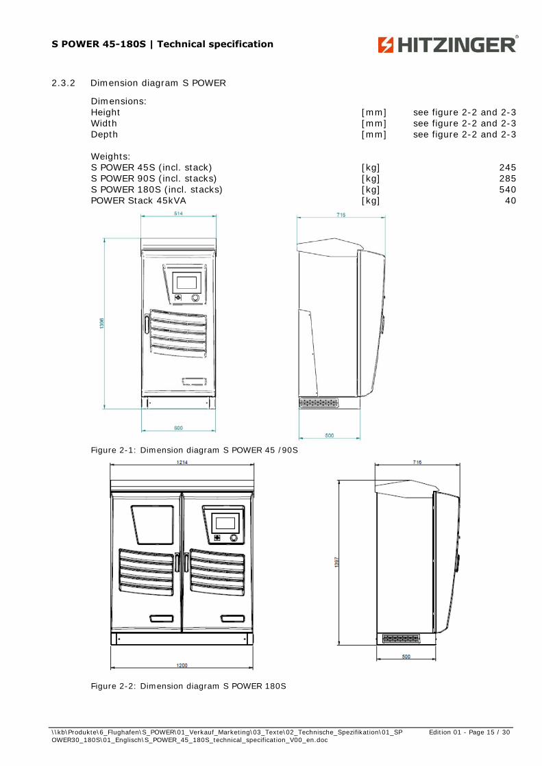
2.3.2 Dimension diagram S POWER
Dimensions: Height [mm] see figure 2-2 and 2-3 Width [mm] see figure 2-2 and 2-3 Depth [mm] see figure 2-2 and 2-3 Weights: S POWER 45S (incl. stack) [kg] 245 S POWER 90S (incl. stacks) [kg] 285 S POWER 180S (incl. stacks) [kg] 540 POWER Stack 45kVA [kg] 40
Figure 2-1: Dimension diagram S POWER 45 /90S
Figure 2-2: Dimension diagram S POWER 180S
S POWER 45-180S | Technical specification
\\kb\Produkte\6_Flughafen\S_POWER\01_Verkauf_Marketing\03_Texte\02_Technische_Spezifikation\01_SPOWER30_180S\01_Englisch\S_POWER_45_180S_technical_specification_V00_en.doc
Edition 01 - Page 16 / 30
50/60 Hz
= ~ =
~
400 Hz
(1) (2) (3) (4) (5)
400Hz -transformer
45kVA Stack
45kVA Stack
50/60 Hz
400 Hz
3 Function of S POWER
3.1 General Discription
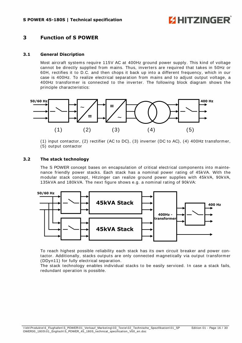
Most aircraft systems require 115V AC at 400Hz ground power supply. This kind of voltage cannot be directly supplied from mains. Thus, inverters are required that takes in 50Hz or 60H, rectifies it to D.C. and then chops it back up into a different frequency, which in our case is 400Hz. To realize electrical separation from mains and to adjust output voltage, a 400Hz transformer is connected to the inverter. The following block diagram shows the principle characteristics:
(1) input contactor, (2) rectifier (AC to DC), (3) inverter (DC to AC), (4) 400Hz transformer, (5) output contactor
3.2 The stack technology
The S POWER concept bases on encapsulation of critical electrical components into mainte-nance friendly power stacks. Each stack has a nominal power rating of 45kVA. With the modular stack concept, Hitzinger can realize ground power supplies with 45kVA, 90kVA, 135kVA and 180kVA. The next figure shows e.g. a nominal rating of 90kVA:
To reach highest possible reliability each stack has its own circuit breaker and power con-tactor. Additionally, stacks outputs are only connected magnetically via output transformer (DDyn11) for fully electrical separation. The stack technology enables individual stacks to be easily serviced. In case a stack fails, redundant operation is possible.

S POWER 45-180S | Technical specification
\\kb\Produkte\6_Flughafen\S_POWER\01_Verkauf_Marketing\03_Texte\02_Technische_Spezifikation\01_SPOWER30_180S\01_Englisch\S_POWER_45_180S_technical_specification_V00_en.doc
Edition 01 - Page 17 / 30
EMI Filter
Boost chokes
AC/DC (3-Level,
PFC)
DC/AC (3-Level)
LC Out-put Fil-
ter
Encapsulated - IP 66
Boost chokes
EMI Filter AC/DC
24V PSU CPU - Base-
board
Power IN
Aux. Power
Power OUT
3.3 Functional description of 45kVA stack
The block diagram given below shows the main components of the S POWER stacks: Placed directly to the input, the EMI filter (electromagnetic interference) limits the con-ducted emissions. Using the auxiliary power input, the control parts of the stack are sup-plied. In addition, the auxiliary power input is used to pre-charge the DC-link voltage with current limitation. Once DC-link pre-charge is completed, the main current flow goes via the power input. Thereby, the boost chokes are required to gain a rectified DC-link voltage that is above the mains level. Further the boost chokes in combination with AC-capacitors work as a filter to minimize harmonics on the mains. The used active PFC (power factor correction) converts the 3-phase input voltage (400/480VAC ± 10%) to a regulated DC-voltage. It is characterized by an active input cur-rent shaping which results in sinusoidal input currents with power factor 1. Through the PWM-control of the IGBT-rectifier, the DC-link voltage deviation is held at a constant level regardless of input voltage or input frequency fluctuations. This can be interpreted as a de-coupling of input to output, which leads to a high quality of the 400Hz voltage. Only capacitors with high quality from well-known manufacturers are used in the controlled DC-link. Their function is to block voltage ripple and transient peaks. The capacitors are constructively placed in the cooling air-flow, which increases the life-cycle of the capacitors drastically. The DC / AC inverter converts the DC voltage back to AC. Using the LC output low-pass fil-ter, the harmonics of the 400Hz voltage will be reduced to a minimum. For highest efficiency, rectifier (AC/DC) as well as inverter (DC/AC) are both using the latest 3-level PWM (pulse with modulation) technology. The CPU baseboard does the digital logic for controlling, monitoring and measuring of volt-age, current, temperature (cooling fans), power and power factor on each stack input and stack output phase. Additionally, the CPU communicate to ACON (Hitzinger PLC) and to other stacks (synchronisation, load sharing).

S POWER 45-180S | Technical specification
\\kb\Produkte\6_Flughafen\S_POWER\01_Verkauf_Marketing\03_Texte\02_Technische_Spezifikation\01_SPOWER30_180S\01_Englisch\S_POWER_45_180S_technical_specification_V00_en.doc
Edition 01 - Page 18 / 30
4 Main components
4.1 POWER Stack
The Hitzinger POWER Stack includes all electronic components as well as fans, cooling ele-ments, active power factor correction (PFC), inverter, output-filters, devices for 50Hz and 400Hz connection plugs and a LED status display. The POWER Stacks have an easy access through the front door. The front door is locked with a double bit key for reasons of safety. The plug&play system featured by the HITZINGER Stack technology enables individual stacks to be easily serviced. In case a stack fails, redundant operation is possible.
Figure 4-1: Plug&Play System Stack-Technology
4.1.1 Internal Stack system
The Power Stacks include all critical signal- and powerelectronic-parts and are mounted in a hermetically enclosed area and are protected against dust and moisture.
4.1.2 Active Power Factor Correction (PFC) – active rectification (AC/DC)
The used 3-phase/ 3-pulse-rectifier is a rectification, which converted the 3-phase input voltage (400/480VAC ± 10%) to a regulated DC-voltage. The active PFC is characterized by lower harmonic content and sinusoidal input currents compared to conventional six-pulse (B6) or twelve-pulse (B12) bridge circuits. Also the phase position of the input currents is controlled; this is why the power factor is closed to the ideal value=1. Through the PWM-control of the IGBT-rectifier the DC-link voltage deviation is held at a constant level regard-less of input voltage or input frequency fluctuations. A high quality of the 400Hz-output voltage is produced by the decoupling of input to output. No external multi-pulse trans-formers or input-filters are required. All components are integrated in the S POWER Stack!
Variable speed fans
Bus interface status indication
Power plugs (input/output)

S POWER 45-180S | Technical specification
\\kb\Produkte\6_Flughafen\S_POWER\01_Verkauf_Marketing\03_Texte\02_Technische_Spezifikation\01_SPOWER30_180S\01_Englisch\S_POWER_45_180S_technical_specification_V00_en.doc
Edition 01 - Page 19 / 30
4.1.3 Intermediate circuit capacitors
Only capacitors with high quality from well-known manufacturers are used in the controlled DC-link. The capacitors are constructively placed in the cooling air-flow, which increases the life-cycle of the capacitors drastically.
4.1.4 DC / AC inverter
The three DC / AC transformers are equipped with a low-pass filter that transforms the DC-voltage of the DC-link in a 115AC voltage with an output frequency of 400Hz. The 3-phase current can be realized via the connection of the 3 DC / AC transformers. By the use of the latest 3-level inverter technology very high efficiencies can be realized. The potential sepa-ration between input and output voltage and the voltage adjustment is created by a con-nected transformer.
4.1.5 Baseboard
Especially for S POWER designed digital logic unit records every status of the POWER Stacks. This digital measurement and control device is state-of-the-art technology and communicates between the stacks and the touch panel. Digital logic for controlling, moni-toring and measuring (voltage, current, temperature, power and PF on each stack input and stack output phase, interstack-communication for synchronisation and load sharing).
4.1.6 Modular Stack design
6 x Power module + 1 x intermediate circuit + 1 x controller board
50/60Hzinput
400Hzoutput
AC/DC 800Vdc DC/AC
50/60Hzinput
400Hzoutput
AC/DC 800Vdc DC/AC
4.1.7 400Hz-Transformer
Potential separation between input and output voltage and different stack outputs and earth (4kVac withstand). Vector connection DDyn11
S POWER 45-180S | Technical specification
\\kb\Produkte\6_Flughafen\S_POWER\01_Verkauf_Marketing\03_Texte\02_Technische_Spezifikation\01_SPOWER30_180S\01_Englisch\S_POWER_45_180S_technical_specification_V00_en.doc
Edition 01 - Page 20 / 30
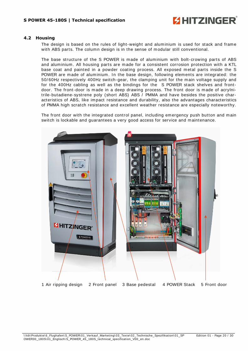
4.2 Housing The design is based on the rules of light-weight and aluminium is used for stack and frame with ABS parts. The column design is in the sense of modular still conventional. The base structure of the S POWER is made of aluminium with bolt-crowing parts of ABS and aluminium. All housing parts are made for a consistent corrosion protection with a KTL base coat and painted in a powder coating process. All exposed metal parts inside the S POWER are made of aluminium. In the base design, following elements are integrated: the 50/60Hz respectively 400Hz switch-gear, the clamping unit for the main voltage supply and for the 400Hz cabling as well as the bindings for the S POWER stack shelves and front-door. The front-door is made in a deep drawing process. The front door is made of acrylni-trile-butadiene-systrene poly (short ABS) ABS / PMMA and have besides the positive char-acteristics of ABS, like impact resistance and durability, also the advantages characteristics of PMMA high scratch resistance and excellent weather resistance are especially noteworthy. The front door with the integrated control panel, including emergency push button and main switch is lockable and guarantees a very good access for service and maintenance.
1 Air ripping design 2 Front panel 3 Base pedestal 4 POWER Stack 5 Front door
S POWER 45-180S | Technical specification
\\kb\Produkte\6_Flughafen\S_POWER\01_Verkauf_Marketing\03_Texte\02_Technische_Spezifikation\01_SPOWER30_180S\01_Englisch\S_POWER_45_180S_technical_specification_V00_en.doc
Edition 01 - Page 21 / 30
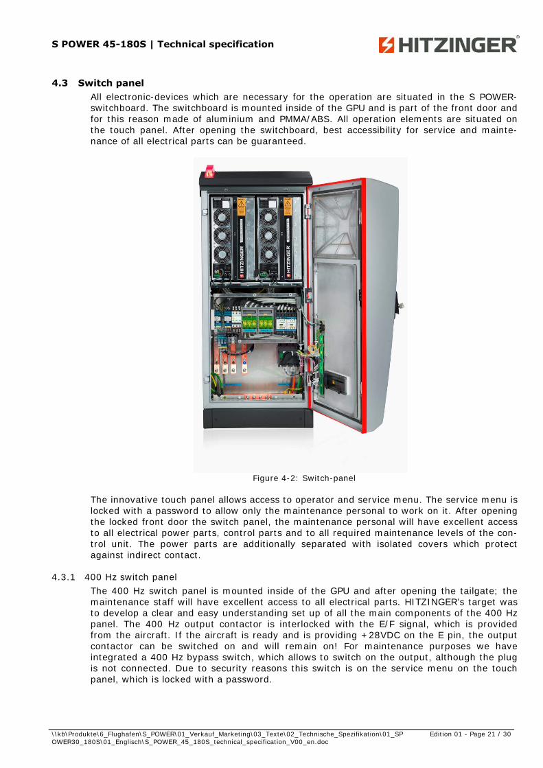
4.3 Switch panel All electronic-devices which are necessary for the operation are situated in the S POWER-switchboard. The switchboard is mounted inside of the GPU and is part of the front door and for this reason made of aluminium and PMMA/ABS. All operation elements are situated on the touch panel. After opening the switchboard, best accessibility for service and mainte-nance of all electrical parts can be guaranteed.
Figure 4-2: Switch-panel
The innovative touch panel allows access to operator and service menu. The service menu is locked with a password to allow only the maintenance personal to work on it. After opening the locked front door the switch panel, the maintenance personal will have excellent access to all electrical power parts, control parts and to all required maintenance levels of the con-trol unit. The power parts are additionally separated with isolated covers which protect against indirect contact.
4.3.1 400 Hz switch panel The 400 Hz switch panel is mounted inside of the GPU and after opening the tailgate; the maintenance staff will have excellent access to all electrical parts. HITZINGER’s target was to develop a clear and easy understanding set up of all the main components of the 400 Hz panel. The 400 Hz output contactor is interlocked with the E/F signal, which is provided from the aircraft. If the aircraft is ready and is providing +28VDC on the E pin, the output contactor can be switched on and will remain on! For maintenance purposes we have integrated a 400 Hz bypass switch, which allows to switch on the output, although the plug is not connected. Due to security reasons this switch is on the service menu on the touch panel, which is locked with a password.
S POWER 45-180S | Technical specification
\\kb\Produkte\6_Flughafen\S_POWER\01_Verkauf_Marketing\03_Texte\02_Technische_Spezifikation\01_SPOWER30_180S\01_Englisch\S_POWER_45_180S_technical_specification_V00_en.doc
Edition 01 - Page 22 / 30
4.3.1.1 Main components of the 400 Hz switch panel Main fuses output contactors (90 kVA) 400Hz transformer E/F contact relay ACON FS control unit surge arrester (Option)
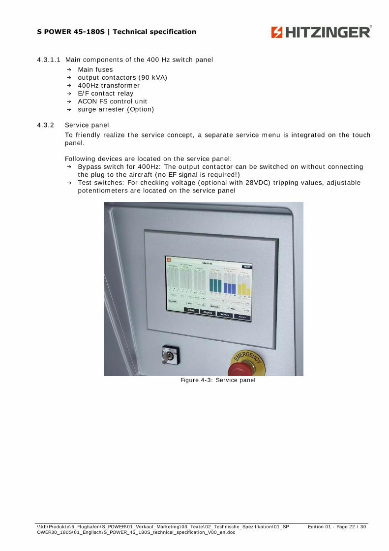
4.3.2 Service panel To friendly realize the service concept, a separate service menu is integrated on the touch panel. Following devices are located on the service panel:
Bypass switch for 400Hz: The output contactor can be switched on without connecting the plug to the aircraft (no EF signal is required!)
Test switches: For checking voltage (optional with 28VDC) tripping values, adjustable potentiometers are located on the service panel
Figure 4-3: Service panel

S POWER 45-180S | Technical specification
\\kb\Produkte\6_Flughafen\S_POWER\01_Verkauf_Marketing\03_Texte\02_Technische_Spezifikation\01_SPOWER30_180S\01_Englisch\S_POWER_45_180S_technical_specification_V00_en.doc
Edition 01 - Page 23 / 30
4.3.3 28 VDC Unit (optional)
4.3.3.1 General The 28 VDC unit can be equipped with one 28 VDC output which can be used either for single or simultaneous operation.
4.3.3.2 Function The 28 VDC unit consists out of 6 modules and each two of them are connected in parallel and supplied between two phases. The resulting supply voltage of 200VAC and 400Hz are rectified and smoothed with capacitors and then fed through an IGBT full bridge inverter into a high-frequency transformer with a com-pact design and a very high power density. The lowest weight of the transformer is possible due to the Ironless Technology and the 30 kHz switching frequency. The transformer reduce the DC voltage from the rectifier (=280VDC) to 28VDC voltage. The output of each module is controlled and measured separately and via an internal bus connected to our can bus, which enables full control and fault diagnosis. The 3 fans are separately temperature controlled and fault protected.
4.3.3.3 Current limitation (optional) For the 28VDC output the current limitation function is an available option. By the help of a current limitation switch preset values can be selected and in the case the selected value is exceeded, the current will be automatically limited and for this reason the aircraft is protected.
4.4 Control panel with HITZINGER ACON microprocessor control unit
4.4.1 General The whole touch panel is situated at the front of the S POWER and is designed according to 3 different operational levels. Because of ergonomically reasons the touch panel is mounted in an oblique position.
Figure 4-4: ACON-Supervision and touch screen

S POWER 45-180S | Technical specification
\\kb\Produkte\6_Flughafen\S_POWER\01_Verkauf_Marketing\03_Texte\02_Technische_Spezifikation\01_SPOWER30_180S\01_Englisch\S_POWER_45_180S_technical_specification_V00_en.doc
Edition 01 - Page 24 / 30
Level 1 – operator level: The number of operational elements and indications is minimized to achieve a maximum of user-friendly operation on the touch panel. The status of the different buttons is displayed on the touch panel. By the help of logical interconnections and the use of different colour codes an easy and unmistakable operation can be guaranteed. Further information like service intervals, fuel level etc. can be simply visualized.
Level 2 – service level:
The service level on the touch panel is locked with a password. In the service menu, the service engineers have access to all switching elements, adjustment elements and indications. Skilled personal can call detailed data like measuring values, calibration values and the failure history on the display of the control unit.
Figure 4-5: Service-level S POWER Stack
Level 3 – service specialist level:
On the level 2 service panel there are interfaces for connecting the programming & diagnostic devices. For this level only qualified specialists have excess.
4.4.2 HITZINGER ACON The new HITZINGER ACON has been developed as a compact control unit under application of the most modern micro-processor technology. It contains all control-, supervision and measurement facilities which are required for ground power supply. In- and output modules are situated decentralised and connected via a bus system (CAN-bus). Consequently a simpler and safer mounting within the switch panel can be achieved. Due to the high current capacity of the outputs there are only a few external relays required, except the power components. The ACON is very simple to operate and easy to attend, for instance, all failure and operation indications are clearly displayed on a touch display and stored in an internal memory of the ACON. A failure recorder stores the last 256 errors, which are shown on the touch display and which can be printed anytime on an external printer. Remote supervision respective control by means of a modem can be done via an interface. Regarding failure protection best precautions have been taken and all in-/ outputs and in-terfaces of the control unit are isolated galvanically by relays or optocouplers. All necessary software-parameters for supervision and control of the ground power supply can be adapted very easily via the interface by means of a personal computer and can also be changed easily. All the above mentioned advantages of the HITZINGER ACON guarantee a high degree of safety, availability and flexibility of the ground power supply.

S POWER 45-180S | Technical specification
\\kb\Produkte\6_Flughafen\S_POWER\01_Verkauf_Marketing\03_Texte\02_Technische_Spezifikation\01_SPOWER30_180S\01_Englisch\S_POWER_45_180S_technical_specification_V00_en.doc
Edition 01 - Page 25 / 30
4.4.2.1 Overview ACON modules
1 ACON-CPU processor/memory ARM9 CPU, 400MHz, 128MB flash, 64MBSDRAM 2 Output-modul up to 16-outputs, isolated 3 I/O-modul high/low 4 measuring modul U/I/W 5 PWM modul (status indication lamp option) 6 28VDC modul (option)
4.4.2.2 Measuring values - indication on the touch display Following values can be shown on the touch display:
Voltage [V] Current [A] Frequency [Hz] Electrical Power [kW] reactive power [kVAr] apparent power [kVA] power factor operation hours [h] operation hours for maintenance [h]
4.4.2.3 Operation indications Following operational indications can be shown on the touch display:
GPU ready Plant in operation Plant in operation (Stand by) Bypass on for each output Output 1 400Hz on Output 2 400Hz on Output 28VDC on (optional) Warning fault Shutdown fault
4.4.2.4 Failure indications Emergency stop button activated Start failure over temperature Output 1 400 Hz over current Output 28VDC over current (optional) Maintenance required Output not accepted
1 2 3 4 5 61 2 3 4 5 6

S POWER 45-180S | Technical specification
\\kb\Produkte\6_Flughafen\S_POWER\01_Verkauf_Marketing\03_Texte\02_Technische_Spezifikation\01_SPOWER30_180S\01_Englisch\S_POWER_45_180S_technical_specification_V00_en.doc
Edition 01 - Page 26 / 30
over current short circuit under voltage (<70V) under voltage (<104V) over voltage (>124V) over voltage (>170V) under frequency (<345Hz) under frequency (<380Hz) over frequency (>420Hz) over frequency (>435Hz) mains under voltage mains over voltage mains under frequency mains over frequency mains under current mains over current 28VDC under voltage (optional) 28VDC over voltage (optional) 28VDC over temperature (optional) 28VDC over current (optional) CAN bus failure
4.4.2.5 Switches and push buttons Main switch on/off Emergency stop push button Output 1 on/off via touch Output 2 on/off via touch Output 28 VDC on/off (optional) via touch Reset via touch

S POWER 45-180S | Technical specification
\\kb\Produkte\6_Flughafen\S_POWER\01_Verkauf_Marketing\03_Texte\02_Technische_Spezifikation\01_SPOWER30_180S\01_Englisch\S_POWER_45_180S_technical_specification_V00_en.doc
Edition 01 - Page 27 / 30
4.5 Operation panel
The front panel of the S POWER is easily reachable from the outside via a touch panel and includes all operating and display elements. All necessary information fort he operation and maintenance including fault finding, are shown on the touch panel which is characterized by an intuitive user interface and can be easily operated with working gloves.
Figure 4-6: Touch panel The control unit is equipped with a resistive glass-film-glass touch which is more resistant to scratches and high temperatures than touch screens with polyester surfaces. In addition, the touch panel has an anti-reflective coating and due to this, it is very well readable even in bright sunlight. A built-in UV filter ensures a long service life. The front plate is made of aluminium with an anodized surface. The sturdy glass-touch and the rear mounting with a special seal in a metal housing with high mechanical strength and high degree of protection (front IP67) make the operating unit resistant against environmental influences, such as de-icer for aircrafts, UV radiation, salt fog, ammonia, aggressive cleaning supplies and other substances. The touch panel is designed for use under extreme conditions. Besides this, it is also shock and vibration resistant.
Figure 4-7. Front panel
S POWER 45-180S | Technical specification
\\kb\Produkte\6_Flughafen\S_POWER\01_Verkauf_Marketing\03_Texte\02_Technische_Spezifikation\01_SPOWER30_180S\01_Englisch\S_POWER_45_180S_technical_specification_V00_en.doc
Edition 01 - Page 28 / 30
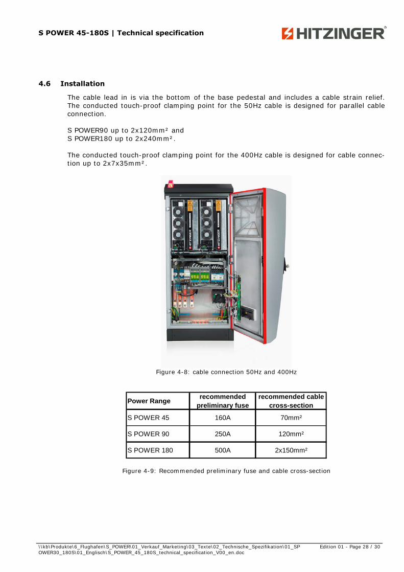
4.6 Installation
The cable lead in is via the bottom of the base pedestal and includes a cable strain relief. The conducted touch-proof clamping point for the 50Hz cable is designed for parallel cable connection. S POWER90 up to 2x120mm² and S POWER180 up to 2x240mm². The conducted touch-proof clamping point for the 400Hz cable is designed for cable connec-tion up to 2x7x35mm².
Figure 4-8: cable connection 50Hz and 400Hz
Power Rangerecommended
preliminary fuserecommended cable
cross-section
S POWER 45 160A 70mm²
S POWER 90 250A 120mm²
S POWER 180 500A 2x150mm²
Figure 4-9: Recommended preliminary fuse and cable cross-section
S POWER 45-180S | Technical specification
\\kb\Produkte\6_Flughafen\S_POWER\01_Verkauf_Marketing\03_Texte\02_Technische_Spezifikation\01_SPOWER30_180S\01_Englisch\S_POWER_45_180S_technical_specification_V00_en.doc
Edition 01 - Page 29 / 30
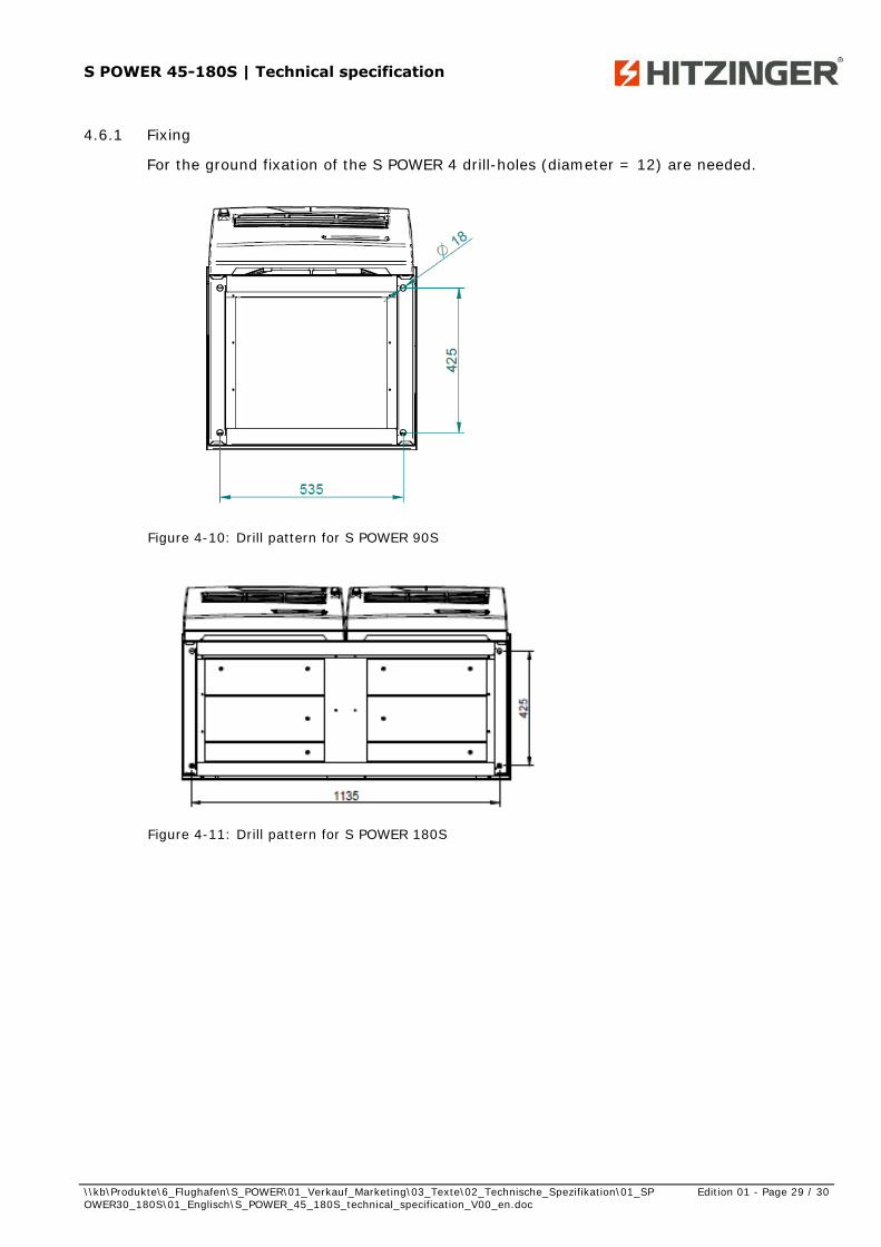
4.6.1 Fixing
For the ground fixation of the S POWER 4 drill-holes (diameter = 12) are needed.
Figure 4-10: Drill pattern for S POWER 90S
Figure 4-11: Drill pattern for S POWER 180S

S POWER 45-180S | Technical specification
\\kb\Produkte\6_Flughafen\S_POWER\01_Verkauf_Marketing\03_Texte\02_Technische_Spezifikation\01_SPOWER30_180S\01_Englisch\S_POWER_45_180S_technical_specification_V00_en.doc
Edition 01 - Page 30 / 30
5 Contact
5.1 Sales department
JOCHEN PHILIPP Business Unit Manager | Airport Equipment
[email protected] | www.hitzinger.at T +43 732 381681 260
MARKUS HONES Sales Manager | Airport Equipment
[email protected] | www.hitzinger.at T +43 732 381681 261
STEFAN KUEHR Sales Manager | Airport Equipment
[email protected] | www.hitzinger.at T +43 732 381681 262
MICHAEL KAISER Key Account Manager | Airport Equipment
[email protected] | www.hitzinger.at T +43 732 381681 263
ROBERT BRANDL Project Manager | Airport Equipment
[email protected] | www.hitzinger.at T +43 732 381681 267
GUNNAR KORB Product Manager | Airport Equipment
[email protected] | www.hitzinger.at T +43 732 381681 266
5.2 Service department
JOHANN ZWERGER Leiter Kundendienst | Head of After Sales
[email protected] | www.hitzinger.at T +43 732 381681 300
PETER OBERPEILSTEINER Ersatzteile | Spare parts
[email protected] | www.hitzinger.at T +43 732 381681 366