s pumps, range 70 - grundfos
TRANSCRIPT

GRUNDFOS DATA BOOKLET
S pumps, range 70107 to 188 HP60 Hz ANSI

Ta
ble
of c
on
ten
ts
2
S pumps, range 70
1. Introduction 3Introduction 3Applications 3Main constructional features 3
2. Performance range 4Performance range overview, S pumps 4Performance range, S pumps, range 70 5List of pump curves 5
3. Identification 6Type key 6Pump nameplate 6FM approval plate 7
4. Selection of product 8Ordering the product 8
5. Product range 9Explosion-proof pumps 9
6. Variants 11List of variants 11
7. Construction 12Sectional drawings, motors 12Components and material specification 20
8. Product description 22Features 22Operating conditions 23Motor range 24Explosion-proof pumps 24Level controllers 24Wiring diagrams 28
9. Curve charts and technical data 29How to read the curve charts 29Curve conditions 30Pump performance testing 30Performance-test types for end-suction pumps 31Specifying acceptance grades 34Certificates 35Witness test 35
10. Performance curves and technical data 36Low pressure 36Medium pressure 38High pressure 42
11. Accessories 48Accessories (for installation) 48Other accessories 49
12. Dimensions 50Recommendation for pump foundations 50Basic pump 51Installation on auto-coupling system 53Dry, vertical installation on concrete foundation 57Dry, horizontal installation on base stand 59
13. Weights 61
14. Flange forces 62
15. Grundfos Product Center 63Grundfos GO 64

Intr
od
uc
tio
n
S pumps, range 70 1
1. Introduction
IntroductionThis product guide deals with Grundfos heavy-duty sewage pumps, type S, range 70.
Fig. 1 S pump, range 70
S pumps, range 70, are a range of free-flow channel impeller pumps specifically designed for pumping sewage and wastewater in a wide range of municipal, private and industrial applications.The pumps are made of resistant materials, such as cast iron and stainless steel. These materials ensure a proper operation.The pumps are fitted with motors from 107 to 188 HP (80 kW to 140 kW). The motors are either 4-, 6- or 8-pole motors, depending on the motor size.The free passage in the pumps is 3.5" to 5.7" (90 to 145 mm).The pumps are available for these types of installation: • submerged installation on auto-coupling system• submerged installation, free-standing• dry installation, vertical• dry installation, horizontal.
ApplicationsS pumps are designed for applications such as:• raw-water intake• wastewater treatment plants• municipal pumping stations • public buildings • residential housing• blocks of apartments• industries• parking garages • underground car parks • car-wash areas • restaurants and hotels. The pumps are suitable for both temporary and permanent installation. The lifting bracket fitted on the pumps facilitates easy transportation as well as installation at the installation site.
Main constructional features• Leak-proof connection via the Grundfos SmartSeal
sealing system• double mechanical shaft seal system for reliable
sealing between pumped liquid and motor• watertight cable entry• moisture switch for continuous monitoring of motor
housing and automatic cut-off power in case liquid penetrates into motor top area or into stator housing
• self-cleaning channel impeller with long vanes reducing the risk of jamming or clogging
• SmartTrim system allowing easy adjustment of impeller clearance and maintaining maximum pump efficiency over pump lifetime
• motor in insulation class H [356 °F (180 °C)] with class F [311 °F (155 °C)] temperature rise, enclosure class IP68 with three thermal sensors in stator windings
• shaft seal condition monitoring via water-in-oil sensor (optional)
• explosion-proof motors for applications involving potential risk of explosion
• stainless steel versions for use in corrosive or aggressive liquids:– stainless steel impeller, cast iron pump and motor
housing– stainless steel pump housing, flange and impeller,
cast iron motor housing made entirely of corrosion-resistant stainless steel.
TM07
083
1 07
18
3

Pe
rform
an
ce
ran
ge
S pumps, range 702
4
2. Performance range
Performance range overview, S pumps
TM06
493
4 32
15��� ��� ��� ��� ��� ��� ������ ���� ���� ���� ���� ���� ����� ����� ������� ������
�
��
��
��
��
��
��
�
���
���
���
���
�����
�� �� �� �� ��� ������ ��� ��� ��� ��� ���������� ���� ���� �������
�
�
�
���
����
��
��
��
���������
����
�����
��
���
����
��
���
��

Pe
rfo
rma
nc
e r
an
ge
S pumps, range 70 2
Performance range, S pumps, range 70
List of pump curves
3 x 460 V
TM04
661
0 48
180 1000 2000 3000 4000 5000 6000 7000 8000 9000 10000 11000 12000 13000 14000Q [US GPM]
25
30
40
50
60
70
80
100
150
200
250
300[ft]H
0 100 200 300 400 500 600 700 800 Q [l/s]
8
91010
20
30
40
50
60
70
80
90
[m]H
60 Hz
S PumpsRange 70
S1.30.A80 S2.40.A100
S3.45.A120
S2.55.A120
S2.40.A80
S3.45.A200
S2.45.A100
S2.35.A80
Pump typePressure
rangeCurve chart
on page
S3.45.A200.1070.8.70LLow 36
S3.45.A200.1880.6.70LS2.40.A80.1270/1610.4.70M
Medium38
S2.40.A80.1470.6.70MS3.45.A120.1070/1880.8.70M 40S1.30.A80.1200.4.70H
High
42S2.35.A80.1270/1610.4.70H 44S2.40.A100.1070.8.70H
46S2.45.A100.1880.8.70HS2.45.A100.1470.6.70H
5
Ide
ntific
atio
n
S pumps, range 703
6
3. Identification
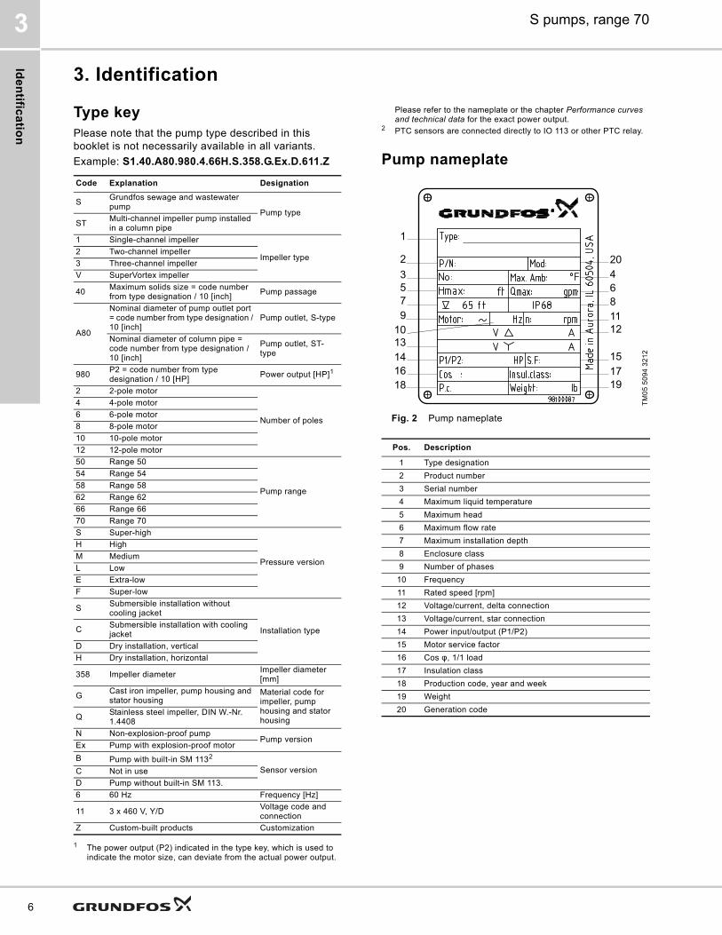
Type keyPlease note that the pump type described in this booklet is not necessarily available in all variants.Example: S1.40.A80.980.4.66H.S.358.G.Ex.D.611.Z
1 The power output (P2) indicated in the type key, which is used to indicate the motor size, can deviate from the actual power output.
Please refer to the nameplate or the chapter Performance curves and technical data for the exact power output.
2 PTC sensors are connected directly to IO 113 or other PTC relay.
Pump nameplate
Fig. 2 Pump nameplate
Code Explanation Designation
S Grundfos sewage and wastewater pump
Pump typeST Multi-channel impeller pump installed
in a column pipe1 Single-channel impeller
Impeller type2 Two-channel impeller3 Three-channel impellerV SuperVortex impeller
40 Maximum solids size = code number from type designation / 10 [inch] Pump passage
A80
Nominal diameter of pump outlet port = code number from type designation / 10 [inch]
Pump outlet, S-type
Nominal diameter of column pipe = code number from type designation / 10 [inch]
Pump outlet, ST-type
980 P2 = code number from type designation / 10 [HP] Power output [HP]1
2 2-pole motor
Number of poles
4 4-pole motor6 6-pole motor8 8-pole motor10 10-pole motor12 12-pole motor50 Range 50
Pump range
54 Range 5458 Range 5862 Range 6266 Range 6670 Range 70S Super-high
Pressure version
H HighM MediumL LowE Extra-lowF Super-low
S Submersible installation without cooling jacket
Installation typeC Submersible installation with cooling jacket
D Dry installation, verticalH Dry installation, horizontal
358 Impeller diameter Impeller diameter [mm]
G Cast iron impeller, pump housing and stator housing
Material code for impeller, pump housing and stator housingQ Stainless steel impeller, DIN W.-Nr.
1.4408N Non-explosion-proof pump
Pump versionEx Pump with explosion-proof motorB Pump with built-in SM 1132
Sensor versionC Not in useD Pump without built-in SM 113.6 60 Hz Frequency [Hz]
11 3 x 460 V, Y/D Voltage code and connection
Z Custom-built products Customization
TM05
509
4 32
12
Pos. Description
1 Type designation2 Product number3 Serial number4 Maximum liquid temperature5 Maximum head6 Maximum flow rate7 Maximum installation depth8 Enclosure class9 Number of phases
10 Frequency11 Rated speed [rpm]12 Voltage/current, delta connection13 Voltage/current, star connection14 Power input/output (P1/P2)15 Motor service factor16 Cos φ, 1/1 load17 Insulation class18 Production code, year and week19 Weight 20 Generation code
1
23 4
20
5 67 89
101112
1314 1516 1718 19

Ide
nti
fic
ati
on
S pumps, range 70 3
FM approval plateThe certified pumps (FM pumps) are supplied with an approval plate fixed on motor top cover.
Fig. 3 FM approval plate
The approval plate gives the following details:
FM certification and classification
TM06
1738
091
8
FM approval symbol
Class I Permitted for locations where flammable gases or vapors may be present.
Division 1
Permitted for locations where flammable or combustible gases can exist under normal operating conditions or because of repair, breakdown or faulty operation of equipment.
Group C and D
Permitted for specific gases or vapors of Group C and D that will be present.
T3C Temperature class (T code)Surface temperature max. 320 °F (160 °C)
Type FM listing code (e.g. S50X13.5/4.60)
yyww/no Production year, week and serial number (e.g. 1052/123456)
Pump Approval
50-70 Class I Division 1 Group C and D Hazardous (Classified) Locations. Temperature class T3C.
Type
yyww/no
Warnings:Thermal and moisture switchesmust always be connected.Do not open when energized. Cable temperature may exceed 158°F. Not including alcohols(methanol) or aliphatic hydrocarbons(hexane). Caution: For cable replacement, see instruction manual. Continuous operation. For converter operation, see manual.
Thermally protected
CLASS I DIVISION 1GROUP C AND D, T3C/T3
Ta= 0°C to + 40°CM
ade
in H
-800
0 S
zéke
sfeh
érvá
r, H
unga
ry
DK-8850 Bejringbro, Denmark
7

Se
lec
tion
of p
rod
uc
t
S pumps, range 704
8
4. Selection of product
Ordering the productWhen ordering the product, you need to take the following four aspects into consideration.1. pump2. custom-built variation (option)3. accessories4. controller.
PumpUse the online selection tool in Grundfos Product Center to find the best suited pump for your application or use Product range, page 9 and Type key, page 6 to identify the pump that best fulfils your needs. The list below is a detailed description of the product you get if you order the following pump:
• Pump as specified in the type key• 50 ft (15 m) cable• Paint: Black, NCS S9000-N/RAL 9005, gloss 30,
thickness 150 μ• Water-in-oil sensor• Three thermal switches (Klixon), one in each phase,
or three thermal sensors (PTC)• One moisture switch below the motor top cover and
one in the stator housing in the bottom of the motor.• ANSI-HI centrifugal pump test 11.6:2012,
acceptance level 3B.See Performance curves and technical data, page 36 for selection of a standard product range.Note: Product-specific data for the pump can also be seen online in Grundfos Product Center using the product number 97632349.
Custom-built variantsThe S pumps can be customized to meet individual requirements. Many pump features and options are available for customization, e.g. explosion-proof versions, various cable lengths or special materials. Variants can be seen in List of variants, page 11. For requirements or designs not included in the list, contact Grundfos.
AccessoriesDepending on the installation type, you may need to order accessories. See Accessories, page 48 for selection of the correct accessories.Note: Ordered accessories are not fitted from factory.
ControllerGrundfos Dedicated Controls (DC) is available.
Fig. 4 Grundfos Dedicated Controls
Grundfos Dedicated Controls is a control system designed for installation in either commercial buildings or network pumping stations with one to six pumps. As standard, the system is supplied with application-optimized software and can be configured to meet your specific pumping needs.For more information about Level controllers, see page 24.
Pump Product noS2.45.A100.1880.6.70H.H.465.G.Ex.D 97632349
TM06
650
1 15
15

Pro
du
ct
ran
ge
S pumps, range 70 5
5. Product range
Explosion-proof pumpsAll pumps given here can be delivered as non-explosion-proof pumps, if required.Note: WIO sensor is standard for explosion-proof pumps.
Cast iron, 3 x 460 V
1 Pumps of installation type H include the standard horizontal stand. Pumps with material code G or Q include a painted-steel stand. If another horizontal stand is required, order a pump of installation type D together with the required stand.
2 Installation type S and C pumps with outlet flange size ANSI 10" (DN 250) and higher are supplied with guide claw mounted on the flange.
Pump typeCable length
[ft (m)]Pump
Accessories
Horizontal base stand1
To be ordered separately
Vertical base plate
Auto-coupling system2
S2.35.A80.1270.4.70H.S.340.G.Ex.D... 50 (15) 97660727 - - 97506541S2.35.A80.1270.4.70H.C.340.G.Ex.D... 50 (15) 97660728 - - 97506541S2.35.A80.1270.4.70H.D.340.G.Ex.D... 50 (15) 97660729 - 96857815 -S2.35.A80.1270.4.70H.H.340.G.Ex.D... 50 (15) 97660730 96308212 - -S2.40.A80.1270.4.70M.S.332.G.Ex.D... 50 (15) 97660771 - - 97506541S2.40.A80.1270.4.70M.C.332.G.Ex.D... 50 (15) 97660772 - - 97506541S2.40.A80.1270.4.70M.D.332.G.Ex.D... 50 (15) 97660773 - 96857815 -S2.40.A80.1270.4.70M.H.332.G.Ex.D... 50 (15) 97660774 96308212 - -S2.45.A100.1470.6.70H.S.443.G.Ex.D... 50 (15) 97660775 - - 97510048S2.45.A100.1470.6.70H.C.443.G.Ex.D... 50 (15) 97660776 - - 97510048S2.45.A100.1470.6.70H.D.443.G.Ex.D... 50 (15) 97660777 - 96857816 -S2.45.A100.1470.6.70H.H.443.G.Ex.D... 50 (15) 97660779 96308192 - -S2.55.A120.1470.6.70M.S.420.G.Ex.D... 50 (15) 97660780 - - 97510049S2.55.A120.1470.6.70M.C.420.G.Ex.D... 50 (15) 97660781 - - 97510049S2.55.A120.1470.6.70M.D.420.G.Ex.D... 50 (15) 97660782 - 96857816 -S2.55.A120.1470.6.70M.H.420.G.Ex.D... 50 (15) 97660783 96308255 - -S2.35.A80.1610.4.70H.S.361.G.Ex.D... 50 (15) 97660784 - - 97506541S2.35.A80.1610.4.70H.C.361.G.Ex.D... 50 (15) 97660785 - - 97506541S2.35.A80.1610.4.70H.D.361.G.Ex.D... 50 (15) 97660786 - 96857815 -S2.35.A80.1610.4.70H.H.361.G.Ex.D... 50 (15) 97660787 96308212 - -S2.40.A80.1610.4.70M.S.355.G.Ex.D... 50 (15) 97660788 - - 97506541S2.40.A80.1610.4.70M.C.355.G.Ex.D... 50 (15) 97660789 - - 97506541S2.40.A80.1610.4.70M.D.355.G.Ex.D... 50 (15) 97660790 - 96857815 -S2.40.A80.1610.4.70M.H.355.G.Ex.D... 50 (15) 97660791 96308212 - -S2.45.A100.1880.6.70H.S.465.G.Ex.D... 50 (15) 97660792 - - 97510048S2.45.A100.1880.6.70H.C.465.G.Ex.D... 50 (15) 97660793 - - 97510048S2.45.A100.1880.6.70H.D.465.G.Ex.D... 50 (15) 97660794 - 96857816 -S2.45.A100.1880.6.70H.H.465.G.Ex.D... 50 (15) 97660795 96308192 - -S2.40.A100.1070.8.70H.S.523.G.Ex.D... 50 (15) 99442998 - - 97510048S2.40.A100.1070.8.70H.C.523.G.Ex.D... 50 (15) 99442999 - - 97510048S2.40.A100.1070.8.70H.D.523.G.Ex.D... 50 (15) 99443000 - 96857816 -S2.40.A100.1070.8.70H.H.523.G.Ex.D... 50 (15) 99443001 96308192S3.45.A200.1880.6.70L.S.371.G.Ex.D... 50 (15) 97660800 - - 97510050S3.45.A200.1880.6.70L.C.371.G.Ex.D... 50 (15) 97660801 - - 97510050S3.45.A200.1880.6.70L.D.371.G.Ex.D... 50 (15) 97660802 - 96867808 -S3.45.A200.1880.6.70L.H.371.G.Ex.D... 50 (15) 97660803 96308192 - -S3.45.A120.1880.6.70M.S.407.G.Ex.D... 50 (15) 97660804 - - 97510049S3.45.A120.1880.6.70M.C.407.G.Ex.D... 50 (15) 97660805 - - 97510049S3.45.A120.1880.6.70M.D.407.G.Ex.D... 50 (15) 97660806 - 96857816 -S3.45.A120.1880.6.70M.H.407.G.Ex.D... 50 (15) 97660807 96308192 - -S3.45.A200.1070.8.70L.S.402.G.Ex.D... 50 (15) 97660808 - - 97510050S3.45.A200.1070.8.70L.C.402.G.Ex.D... 50 (15) 97660809 - - 97510050S3.45.A200.1070.8.70L.D.402.G.Ex.D... 50 (15) 97660810 - 96867808 -S3.45.A200.1070.8.70L.H.402.G.Ex.D... 50 (15) 97660811 96308192 - -S3.45.A120.1070.8.70M.S.442.G.Ex.D.... 50 (15) 97660812 - - 97510049S3.45.A120.1070.8.70M.C.442.G.Ex.D... 50 (15) 97660813 - - 97510049S3.45.A120.1070.8.70M.D.442.G.Ex.D... 50 (15) 97660814 - 96857816 -S3.45.A120.1070.8.70M.H.442.G.Ex.D... 50 (15) 97660815 96308192 - -
9

Pro
du
ct ra
ng
e
S pumps, range 705
10
Stainless steel, 3 x 460 V
1 Pumps of installation type H include the standard horizontal stand. Pumps with material code G or Q include a painted-steel stand. If another horizontal stand is required, order a pump of installation type D together with the required stand.
2 Installation type S and C pumps with outlet flange size ANSI 10" (DN 250) and higher are supplied with guide claw mounted on the flange.
Pump typeCable length
[ft (m)]Pump
Accessories
Horizontal base stand1
To be ordered separately
Vertical base plate
Auto-coupling system2
S2.35.A80.1270.4.70H.S.340.G.Ex.D... 50 (15) 97663765 - - 97506541S2.35.A80.1270.4.70H.C.340.G.Ex.D... 50 (15) 97663766 - - 97506541S2.35.A80.1270.4.70H.D.340.G.Ex.D... 50 (15) 97663767 - 96857815 -S2.35.A80.1270.4.70H.H.340.G.Ex.D... 50 (15) 97663768 96308212 - -S2.40.A80.1270.4.70M.S.332.G.Ex.D... 50 (15) 97663769 - - 97506541S2.40.A80.1270.4.70M.C.332.G.Ex.D... 50 (15) 97663770 - - 97506541S2.40.A80.1270.4.70M.D.332.G.Ex.D... 50 (15) 97663771 - 96857815 -S2.40.A80.1270.4.70M.H.332.G.Ex.D... 50 (15) 97663772 96308212 - -S2.45.A100.1470.6.70H.S.443.G.Ex.D... 50 (15) 97663773 - - 97510048S2.45.A100.1470.6.70H.C.443.G.Ex.D... 50 (15) 97663774 - - 97510048S2.45.A100.1470.6.70H.D.443.G.Ex.D... 50 (15) 97663775 - 96857816 -S2.45.A100.1470.6.70H.H.443.G.Ex.D... 50 (15) 97663776 96308192 - -S2.55.A120.1470.6.70M.S.420.G.Ex.D... 50 (15) 97663777 - - 97510049S2.55.A120.1470.6.70M.C.420.G.Ex.D... 50 (15) 97663778 - - 97510049S2.55.A120.1470.6.70M.D.420.G.Ex.D... 50 (15) 97663779 - 96857816 -S2.55.A120.1470.6.70M.H.420.G.Ex.D... 50 (15) 97663780 96308255 - -S2.35.A80.1610.4.70H.S.361.G.Ex.D... 50 (15) 97663781 - - 97506541S2.35.A80.1610.4.70H.C.361.G.Ex.D... 50 (15) 97663782 - - 97506541S2.35.A80.1610.4.70H.D.361.G.Ex.D... 50 (15) 97663783 - 96857815 -S2.35.A80.1610.4.70H.H.361.G.Ex.D... 50 (15) 97663784 96308212 - -S2.40.A80.1610.4.70M.S.355.G.Ex.D... 50 (15) 97663785 - - 97506541S2.40.A80.1610.4.70M.C.355.G.Ex.D... 50 (15) 97663786 - - 97506541S2.40.A80.1610.4.70M.D.355.G.Ex.D... 50 (15) 97663787 - 96857815 -S2.40.A80.1610.4.70M.H.355.G.Ex.D... 50 (15) 97663788 96308212 - -S2.45.A100.1880.6.70H.S.465.G.Ex.D... 50 (15) 97663789 - - 97510048S2.45.A100.1880.6.70H.C.465.G.Ex.D... 50 (15) 97663790 - - 97510048S2.45.A100.1880.6.70H.D.465.G.Ex.D... 50 (15) 97663791 - 96857816 -S2.45.A100.1880.6.70H.H.465.G.Ex.D... 50 (15) 97663792 96308192 - -S2.45.A100.1070.8.70H.S.520.G.Ex.D... 50 (15) 97663793 - - 97510048S2.45.A100.1070.8.70H.C.520.G.Ex.D... 50 (15) 97663794 - - 97510048S2.45.A100.1070.8.70H.D.520.G.Ex.D... 50 (15) 97663795 - 96857816 -S2.45.A100.1070.8.70H.H.520.G.Ex.D... 50 (15) 97663796 96308192 - -S3.45.A200.1880.6.70L.S.371.G.Ex.D... 50 (15) 97663797 - - 97510050S3.45.A200.1880.6.70L.C.371.G.Ex.D... 50 (15) 97663798 - - 97510050S3.45.A200.1880.6.70L.D.371.G.Ex.D... 50 (15) 97663799 - 96867808 -S3.45.A200.1880.6.70L.H.371.G.Ex.D... 50 (15) 97663800 96308192 - -S3.45.A120.1880.6.70M.S.407.G.Ex.D... 50 (15) 97663801 - - 97510049S3.45.A120.1880.6.70M.C.407.G.Ex.D... 50 (15) 97663802 - - 97510049S3.45.A120.1880.6.70M.D.407.G.Ex.D... 50 (15) 97663803 - 96857816 -S3.45.A120.1880.6.70M.H.407.G.Ex.D... 50 (15) 97663804 96308192 - -S3.45.A200.1070.8.70L.S.402.G.Ex.D... 50 (15) 97663805 - - 97510050S3.45.A200.1070.8.70L.C.402.G.Ex.D... 50 (15) 97663806 - - 97510050S3.45.A200.1070.8.70L.D.402.G.Ex.D... 50 (15) 97663807 - 96867808 -S3.45.A200.1070.8.70L.H.402.G.Ex.D... 50 (15) 97663808 96308192 - -S3.45.A120.1070.8.70M.S.442.G.Ex.D.... 50 (15) 97663809 - - 97510049S3.45.A120.1070.8.70M.C.442.G.Ex.D... 50 (15) 97663810 - - 97510049S3.45.A120.1070.8.70M.D.442.G.Ex.D... 50 (15) 97663811 - 96857816 -S3.45.A120.1070.8.70M.H.442.G.Ex.D... 50 (15) 97663812 96308192 - -

Va
ria
nts
S pumps, range 70 6
6. Variants
List of variants
1 Shell Ondina should not be used for pumps with WIO sensor.2 WIO sensor is standard for explosion-proof pumps.
Motor
Various cable lengths
33 ft (10 m)50 ft (15 m)82 ft (25 m)
165 ft (50 m)
EMC power cables Screened power cables for variable-speed drives
33 ft (10 m)50 ft (15 m)82 ft (25 m)
165 ft (50 m)Special motor Special voltagePTC thermistors in windingsSpecial oil Non-toxic Shell Ondina X4201
Motor protection
PTC + moisture switch FPV1Klixon + moisture switch + WIO 2 FPV2aPTC + moisture switch + WIO 2 FPV2bKlixon + moisture switch + WIO 2 + Pt100 at lower and upper bearing + PVS 3 FPV4aPTC + moisture switch + WIO 2 + Pt100 at lower and upper bearing + PVS 3 FPV4b
Materials
Stainless steel lifting bracket AISI 316Stainless steel impeller Duplex ASTM 890 grade 3A and 316 stainless steel Variant QStainless steel shaft AISI 329 / 1.4462Ceramic coatings for pump housing, suction cover and impellers Belzona 1321 and Chesterton ARC 855
Tests
Test at specified duty on standard impeller curveTrimmed impeller for specified duty test Additional test of entire QH curve (including report) 5-10 flows from pump performance curve
Different test standard Efficiency guaranteed by Grundfos
HI 11.6:2012 grade 1B/1U tolerance
HI 11.6:2012 grade 2B/2U tolerance
Vibration test (including report) According to Grundfos factory quality standardPerformance test on dry test stand Not yet availableNPSHr test Not yet availableString test Contact GrundfosWitness test Contact Grundfos
Miscellaneous
Special packaging Contact GrundfosSpecial nameplate Contact GrundfosOther variants Contact Grundfos
11

Co
ns
truc
tion
S pumps, range 707
12
7. Construction
Sectional drawings, motors
Fig. 5 Explosion-proof motor, without cooling jacket (installation type S)
TM06
396
3 13
15

Co
ns
tru
cti
on
S pumps, range 70 7
Fig. 6 Explosion-proof motor with cooling jacket (installation types C, D and H)
TM06
396
5 13
15
13

Co
ns
truc
tion
S pumps, range 707
14
Pumps
Fig. 7 Basic pump, installation types S and C
TM04
258
9 27
08

Co
ns
tru
cti
on
S pumps, range 70 7
Fig. 8 Basic pump, installation types D and H
TM04
270
7 28
08
15

Co
ns
truc
tion
S pumps, range 707
16
Fig. 9 Installation types Sand C pump on auto coupling
TM
04 2
708
4116

Co
ns
tru
cti
on
S pumps, range 70 7
Fig. 10 Installation type D, dry, vertical pump on base plate - version 1
Fig. 11 Installation type D, dry, vertical pump on base plate - version 2
TM04
258
5 27
08TM
04
2588
270
8
17
Co
ns
truc
tion
S pumps, range 707
18
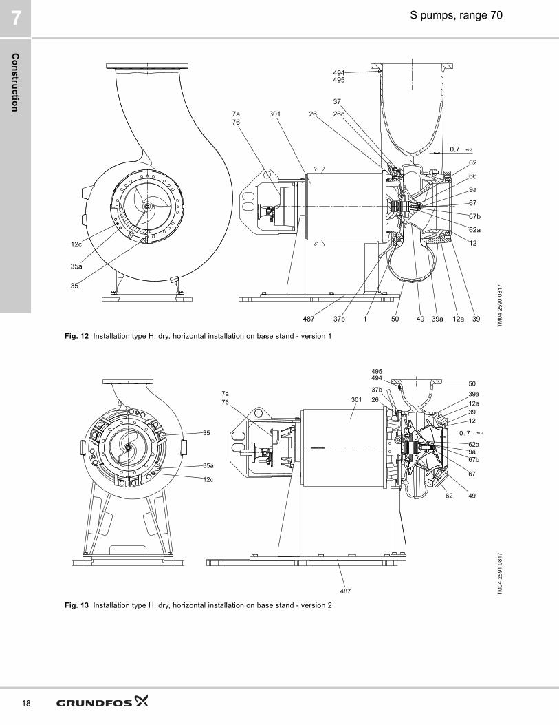
Fig. 12 Installation type H, dry, horizontal installation on base stand - version 1
Fig. 13 Installation type H, dry, horizontal installation on base stand - version 2
TM04
259
0 08
17TM
04 2
591
0817
12c
35a
35
767a 301 26 26c
37
487 37b 1 50 49 39a 12a 39
12
62a
67b
66
9a
62
0.20.7
67
495494
494495
301 2637b
487
767a
123912a39a50
62a9a67b
67
62 49
0 . 7 0.2
35a
35
12c

Co
ns
tru
cti
on
S pumps, range 70 7
Fig. 14 Installation type H, dry, horizontal installation on base stand - version 3
TM07
097
4 09
18
49
12 50
494/495
301 7a76/
35
35a
12c
2637b39 12a 39a
62
6667b
67
0.7 0.2
9a62a
487
19
Co
ns
truc
tion
S pumps, range 707
20
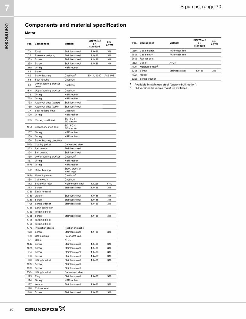
Components and material specification
Motor
1 Available in stainless steel (custom-built option).2 FM versions have two moisture switches.
Pos. Component MaterialDIN W.Nr./
EN standard
AISI/ASTM
7a Rivet Stainless steel 1.4436 31625 Pressure test plug Stainless steel 1.4436 316
25a Screw Stainless steel 1.4436 31626a Screw Stainless steel 1.4436 31637a O-ring NBR rubber48 Stator55 Stator housing Cast iron1 EN-JL 1040 A48 40B58 Seal housing Cast iron
60 Lower bearing bracket cover Cast iron
61c Upper bearing bracket Cast iron72 O-ring NBR rubber
72a O-ring NBR rubber76a Approval plate (pump) Stainless steel76b Approval plate (cable) Stainless steel77 Seal housing cover Cast iron
100 O-ring NBR rubber
105 Primary shaft seal SiC/SiC or SiC/carbon
105b Secondary shaft seal SiC/SiC or SiC/carbon
107 O-ring NBR rubber109 O-ring NBR rubber150 Stator housing complete150c Cooling jacket Galvanized steel153 Ball bearing Stainless steel154 Ball bearing Stainless steel155 Lower bearing bracket Cast iron1
157 O-ring NBR rubber157b O-ring NBR rubber
162 Roller bearing Steel, brass or steel cage
164a Motor top cover Cast iron1
168 Cable entry Cast iron172 Shaft with rotor High tensile steel 1.7225 4140173 Screw Stainless steel 1.4436 316
173b Earth terminal 173c Washer Stainless steel 1.4436 316173e Screw Stainless steel 1.4436 316173f Spring washer Stainless steel 1.4436 316173g Earth connector176a Terminal block176b Screw Stainless steel 1.4436 316176c Terminal block176d Terminal block177a Protection sleeve Rubber or plastic178 Screw Stainless steel 1.4436 316180 Cable clamp PA or cast iron181 Cable ATON
181a Screw Stainless steel 1.4436 316182b Screw Stainless steel 1.4436 316184 Screw Stainless steel 1.4436 316186 Screw Stainless steel 1.4436 316190 Lifting bracket Stainless steel 1.4436 316
190a Screw Stainless steel190b Screw Stainless steel190c Lifting bracket Galvanized steel193 Plug Stainless steel 1.4436 316194 O-ring NBR rubber197 Washer Stainless steel 1.4436 316198 Rubber seal248 Screw Stainless steel 1.4436 316
250 Cable clamp PA or cast iron250a Cable entry PA or cast iron250b Rubber seal252 Cable ATON520 Moisture switch2
520a Screw Stainless steel 1.4436 316522 Holder522c Spring washer
Pos. Component MaterialDIN W.Nr./
EN standard
AISI/ASTM

Co
ns
tru
cti
on
S pumps, range 70 7
Pump
1 Available in stainless steel (custom-built option).
Accessories
1 Pumps of installation type H include the standard horizontal stand. Pumps with material code G or Q include a painted-steel stand. If another horizontal stand is required, order a pump of installation type D together with the required stand.
2 Available in stainless steel (custom-built option).3 Guide claws for ANSI 10" (DN 250) outlets or bigger are factory
fitted.
Pos. Component MaterialDIN W.Nr./
EN standard
AISI/ASTM
1 Intermediate ring Cast iron7a Rivet9a Key (for keyway) Stainless steel 1.4436 31612 Flange Cast iron
12a Inlet cover Cast iron12c Adjusting screw Stainless steel 1.4436 31626 Screw Stainless steel 1.4436 31626c Screw Stainless steel 1.4436 31635 Screw Stainless steel
35a Screw Stainless steel37 O-ring NBR rubber
37b O-ring NBR rubber39 O-ring NBR rubber
39a O-ring NBR rubber
49 Impeller Cast iron1 EN-JL 1050
50 Pump housing Cast iron1 EN-JL 1050
62 O-ring NBR rubber62a O-ring NBR rubber
66 Cap Cast iron or stainless steel
67 Impeller screw Stainless steel 1.4436 31667b O-ring NBR rubber76 Nameplate
301 Motor housing
487 Base stand, horizontal
487a Base plate494 Plug Stainless steel 1.4436 316495 O-ring NBR rubber762 Stand
Pos. Component Material
487 Base stand, horizontal 1 Cast iron or steel701 Auto-coupling base unit Cast iron2
702 Upper guide rail bracket Cast iron2
703 Guide claw3 Cast iron2
762 Base plate, vertical Cast iron or steel
21

Pro
du
ct d
es
crip
tion
S pumps, range 708
22
8. Product description
Features
SmartTrim
On conventional pumps, maintaining factory-set impeller clearance is a time-consuming and costly task. The pumps need to be disconnected from the pipes and to be totally dismantled, and new parts need to be mounted in order to maintain full pumping efficiency. Not so with Grundfos SmartTrim!All Grundfos heavy-duty channel-impeller pumps, whether for submerged or dry installation, are equipped with the unique SmartTrim impeller clearance adjustment system. This enables you to easily restore factory-set impeller clearance and maintain peak pumping efficiency. All you need to do is to tighten the adjustment screws on the exterior of the impeller housing. This can be done on site, quickly and easily, without dismantling the pump and without using special tools.
A: With Grundfos SmartTrim impeller clearance adjustment systemB: Without impeller clearance adjustment system
SmartSeal
For pumps with ANSI 10" (DN 250) outlet or larger, the Grundfos SmartSeal auto-coupling sealing mounted on the pump outlet flange provides a completely leak-proof connection between the pump and the base unit of the auto-coupling system. This optimizes the efficiency of the entire pumping system and keeps operating costs at a minimum.
Bearings
The bearings are greased for life.Main bearings: Double-row angular contact ball bearing. Single or pair-mounted angular contact ball bearings for axial forces and cylindrical roller bearing for radial forces.Support bearings: Single-row deep-groove ball bearing.
Shaft seals
The pumps have a primary and a secondary shaft seal. The material combination of the primary shaft seal of all pump types is silicon carbide/silicon carbide. For the secondary shaft seal, the material combination is silicon carbide/carbon.The shaft seals are placed in the oil chamber of the pump. The oil chamber provides reliable sealing between the pumped liquid and the motor.The shaft seals have no springs or other parts in direct contact with the pumped liquid. This prevents rags and fibers from getting caught. The shaft seals are bidirectional, meaning that they can operate in either direction, thus allowing for opposite rotation caused by back-flow of liquid through the pump.
Motor
The motor is a watertight, totally encapsulated motor.• Insulation class H [356 °F (180 °C)]• Temperature rise class F [189 °F (105 K)]• Enclosure class IP68.For motor protection and sensors, see Sensors, page 23.
Cables
The pumps have H07RN-F AT power cables as standard or screened ATON EMC VSCCB power cables on request.The pumps have H07RN-F 450/750 V control cables as standard or screened ATON VSCB 450/750 V control cables on request.The cables are 50 ft (15 m) long as standard. Other cable lengths are available on request. See List of variants, page 11.The number and dimension of cables depend on the motor size and number of poles.
TM04
239
1 25
08
Factory-set impeller clearance
Efficiency drop in %
Years
B
A
0
3
6
9
12
15
1 2 3 4 5
Motor power[HP (kW)]
VoltageCable size
[power + control]
107 (80)
3 x 460 V
2 x 4 x 25 mm2 + 1 x 10 x 1.5 mm2
127 (95)
147 (110) 2 x 4 x 35 mm2 + 1 x 10 x 1.5 mm2
161 (120) 2 x 4 x 50 mm2 + 1 x 10 x 1.5 mm2
188 (140) 2 x 4 x 70 mm2 + 1 x 10 x 1.5 mm2
Pro
du
ct
de
sc
rip
tio
n
S pumps, range 70 8
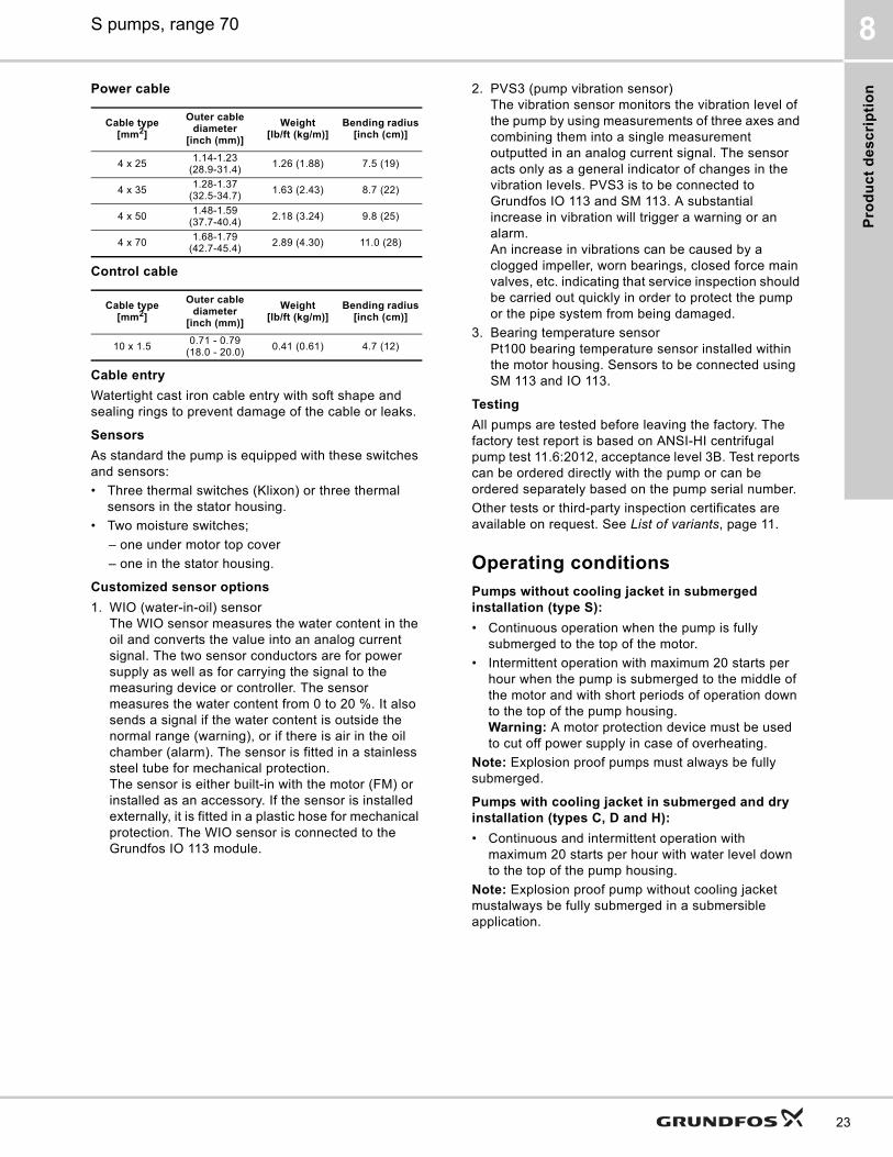
Power cable
Control cable
Cable entry
Watertight cast iron cable entry with soft shape and sealing rings to prevent damage of the cable or leaks.
Sensors
As standard the pump is equipped with these switches and sensors:• Three thermal switches (Klixon) or three thermal
sensors in the stator housing.• Two moisture switches;
– one under motor top cover– one in the stator housing.
Customized sensor options
1. WIO (water-in-oil) sensorThe WIO sensor measures the water content in the oil and converts the value into an analog current signal. The two sensor conductors are for power supply as well as for carrying the signal to the measuring device or controller. The sensor measures the water content from 0 to 20 %. It also sends a signal if the water content is outside the normal range (warning), or if there is air in the oil chamber (alarm). The sensor is fitted in a stainless steel tube for mechanical protection.The sensor is either built-in with the motor (FM) or installed as an accessory. If the sensor is installed externally, it is fitted in a plastic hose for mechanical protection. The WIO sensor is connected to the Grundfos IO 113 module.
2. PVS3 (pump vibration sensor)The vibration sensor monitors the vibration level of the pump by using measurements of three axes and combining them into a single measurement outputted in an analog current signal. The sensor acts only as a general indicator of changes in the vibration levels. PVS3 is to be connected to Grundfos IO 113 and SM 113. A substantial increase in vibration will trigger a warning or an alarm. An increase in vibrations can be caused by a clogged impeller, worn bearings, closed force main valves, etc. indicating that service inspection should be carried out quickly in order to protect the pump or the pipe system from being damaged.
3. Bearing temperature sensorPt100 bearing temperature sensor installed within the motor housing. Sensors to be connected using SM 113 and IO 113.
Testing
All pumps are tested before leaving the factory. The factory test report is based on ANSI-HI centrifugal pump test 11.6:2012, acceptance level 3B. Test reports can be ordered directly with the pump or can be ordered separately based on the pump serial number. Other tests or third-party inspection certificates are available on request. See List of variants, page 11.
Operating conditions
Pumps without cooling jacket in submerged installation (type S):
• Continuous operation when the pump is fully submerged to the top of the motor.
• Intermittent operation with maximum 20 starts per hour when the pump is submerged to the middle of the motor and with short periods of operation down to the top of the pump housing.Warning: A motor protection device must be used to cut off power supply in case of overheating.
Note: Explosion proof pumps must always be fully submerged.
Pumps with cooling jacket in submerged and dry installation (types C, D and H):
• Continuous and intermittent operation with maximum 20 starts per hour with water level down to the top of the pump housing.
Note: Explosion proof pump without cooling jacket mustalways be fully submerged in a submersible application.
Cable type[mm2]
Outer cable diameter
[inch (mm)]
Weight[lb/ft (kg/m)]
Bending radius[inch (cm)]
4 x 25 1.14-1.23 (28.9-31.4) 1.26 (1.88) 7.5 (19)
4 x 35 1.28-1.37(32.5-34.7) 1.63 (2.43) 8.7 (22)
4 x 50 1.48-1.59(37.7-40.4) 2.18 (3.24) 9.8 (25)
4 x 70 1.68-1.79(42.7-45.4) 2.89 (4.30) 11.0 (28)
Cable type[mm2]
Outer cable diameter
[inch (mm)]
Weight[lb/ft (kg/m)]
Bending radius[inch (cm)]
10 x 1.5 0.71 - 0.79 (18.0 - 20.0) 0.41 (0.61) 4.7 (12)
23

Pro
du
ct d
es
crip
tion
S pumps, range 708
24
Pumped liquidspH value: 4-10Liquid temperature: 32-104 °F (0-40 °C)When pumping liquids with a density and/or a kinematic viscosity higher than that of water, use motors with correspondingly higher outputs.
Sound pressure
The sound pressure level of the pump is lower than the limiting values stated in EC Council directive 2006/42/EC relating to machinery (the EC Machinery Directive).
Motor range
Explosion-proof pumps
Approval standardsPumps are approved by FM according to FM3600, FM3615 and FM3615.80.
Explanation to FM approval
Use explosion-proof pumps in potentially explosive environments.Note: All installations must be approved by the local authorities.
Relevant standards/regulations
• FM 3600• FM 3615• FM 3615.80• ANSI/UL 1004-1• ANSI/UL 1004-3
Explosion protection classification (FMus)
Class I, Division 1, Groups C and D, T3 or T3C
Operation with frequency converter
Only temperature class T3
Notified body
FM Approvals
Level controllersGrundfos offers dedicated pump controllers for monitoring liquid levels in the wastewater collecting tanks to ensure correct operation and protection of the pumps. Grundfos pump controllers are ideally suited to Grundfos S pumps, and include:• Grundfos Dedicated Controls (DC)• Grundfos LC controllers
Grundfos DC Controllers
Fig. 15 Grundfos Dedicated Controls control cabinet
Grundfos Dedicated Controls (DC) is a control system designed for installation in municipal wastewater transportation, commercial buildings or network pumping stations with up to six wastewater pumps and an optional mixer or a flush valve.Advanced control and data communication are also possible with the Grundfos Dedicated Controls system. The control cabinets are delivered with a built-in main switch and thermal magnetic circuit breaker.Features and benefits:• Advanced Flow Calculation• Automatic energy optimization• Easy installation and configuration• Configuration wizard• Electrical overview• Advanced data communication• Advanced alarm and warning priority• Supports several languages• Daily emptying• Mixer control or flush valve• User-defined functions• Anti-blocking• Start level variation• Advanced pump alternation with pump groups• SMS scheduling
Motor power [HP (kW)] Number of poles
107 (80) 8127 (95) 4147 (110) 6161 (120) 4188 (140) 6
Gr-
1016
086

Pro
du
ct
de
sc
rip
tio
n
S pumps, range 70 8
• Communication to SCADA, BMS, GRM or cell phone.
Dedicated Controls is ordered either with or without a built-in communication interface module (CIM).The communication module enables the possibility for fieldbus protocol (e.g. PROFIBUS DP, Modbus RTU and PROFINET IO/Modbus TCP) and the communication line.For further information about Grundfos Dedicated Controls, please see Grundfos Product Center:• Grundfos Dedicated Controls, brochure http://
net.grundfos.com/qr/i/96925597• Grundfos iSolutions, brochure http://
net.grundfos.com/qr/i/99249771• Grundfos Controls Guide, product guide http://
net.grundfos.com/qr/i/97954965
Additional features, CUE or VFD
The CUE/VFD (optional), which is either a Grundfos variable frequency drive or a general variable frequency drive, offers better pump protection and a more steady flow through the pipe system.In addition, Grundfos CUE,VFD offers these features and benefits:• Anti-blocking• Automatic energy optimization• Specific-energy test• Output frequency• Monitoring of:
– voltage*– current*– phase sequence*– power*– energy*– torque*
• Reverse start**• Run flushing• Stop flushing• PID control.* These functions are only available with a Grundfos
CUE.** We do not recommend reversing at full speed at
any time. When reduced reverse operation settings are set, make sure constant torque is enabled in Variable Frequency Drive (VFD) (i.e. Grundfos CUE, Siemens Simatic, ABB, Schneider Electric etc.) to have maximum torque available when reversing.
Grundfos LC controllers
The LC 231 pump controller is designed for level control, monitoring and protection of Grundfos pumping stations featuring one pump or two pumps, starting direct-on-line. The LC 231 controller is integrated in a polymer cabinet. The LC 241 is a modular pump controller that has a metal or polymer cabinet and can be customized according to your needs.It is designed for level control, monitoring and protection of Grundfos pumping stations featuring one pump or two pumps, starting direct-on-line with 0-23 A, star-delta with 0-59 A or soft starter with 0-72 A.
IO 113The IO 113 module is a protection module for Grundfos wastewater pumps.IO 113 has inputs for digital and analog pump sensors and can stop the pump if a sensor indicates a pump fault.IO 113 can be connected to the Grundfos Dedicated Controls system and allows advanced monitoring functions:• motor temperature• moisture in motor• water in oil• insulation resistance.
SM 113The SM 113 module is used for collection and transfer of sensor data in pumps and includes a large number of sensors.SM 113 can be placed either inside the pump (allowing fewer sensor conductors out of the pump) or in the control cabinet next to the pump installation. SM 113 works together with IO 113 through a power-line communication using the Grundfos GENIbus protocol.SM 113 can collect data from:• 3 current sensors, 4-20 mA• 3 Pt100 thermal sensors or 3 Pt1000 thermal
sensors• 1 PTC thermal sensor• 1 digital input.
MP 204The MP 204 control cabinet can be used as a stand-alone motor protector. MP 204 may also be incorporated in a Grundfos Dedicated Controls system in which it functions as a motor protector. The pump is protected secondarily by measuring the temperature with a Pt100 sensor and a PTC sensor or thermal switch.
25

Pro
du
ct d
es
crip
tion
S pumps, range 708
26
Fig. 16 Pumps with frequency converter operation
TM06
875
3 11
17
Reset
PET1 T2 G1 A1 G2 A2 K1 K2 R1 R2
D1 D2 D3 D4 D5 D6 D7 D8
P1 P2 P3 P4 P5
A Y B
I1 I2 I3
ON DIP
1 2 3 4 5 6 7 8 9 10
1 2 3 4 5 6 7 8 9 1011 121314
1 2 3 4 5 6 7 8 9 1011 121314
1
1
1 1
T1
T2
2
2
2 2
3
3
3 3
4
4
4 4
5
5
5 5
666 6
7
7
7 7
8
8
8 8
9
9
9 9
+t +t +t
+t
+t
Grundfos CUE, < 335 HP (250 kW), or another frequency converter.
IO 113 SM 113
Dedicated Controls or PLC
Level sensor
SM 113, optional
PVS3 sensor, optional
Moisture switch
WIO sensor, optional
Pt100 sensor,optional
PTC
Thermistor
Thermal switches
Moisture switches
Pt100 in lower bearing
Pt100 in stator
Pt100 in upper bearing
Oil indicator4 to 20 mA
Control cabinet
Wiring diagram

Pro
du
ct
de
sc
rip
tio
n
S pumps, range 70 8
Fig. 17 Pump with MP 204 motor protector
TM06
875
4 11
17
MP 204
Reset
PET1 T2 G1 A1 G2 A2 K1 K2 R1 R2
D1 D2 D3 D4 D5 D6 D7 D8
P1 P2 P3 P4 P5
A Y B
I1 I2 I3
ON DIP
1 2 3 4 5 6 7 8 9 10
1 2 3 4 5 6 7 8 9 1011 121314
1 2 3 4 5 6 7 8 9 1011 121314
1
1
1 1
T1
T2
2
2
2 2
3
3
3 3
4
4
4 4
5
5
5 5
666 6
7
7
7 7
8
8
8 8
9
9
9 9
+t +t +t
+t
+t
MP 204
IO 113 SM 113
Dedicated Controls or PLC
Level sensor
SM 113, optional
PVS3 sensor, optional
Moisture switch
WIO sensor, optional
Pt100 sensor,optional
PTC
Thermistor
Thermal switches
Moisture switches
Pt100 in lower bearing
Pt100 in statorPt100 in upper bearing
Oil indicator4 to 20 mA
Control cabinet
Wiring diagram
27

Pro
du
ct d
es
crip
tion
S pumps, range 708
28
Wiring diagrams
Fig. 18 Wiring diagrams, Y-connected (460 V) for standard sensors
Fig. 19 Wiring diagram for sensors (with WIO sensor)
TM06
493
7 35
15 /
TM05
175
8 36
11
Sensors
Thermal switch
Moisture switches
Pt100 lower bearings
Pt100 stator
Thermistor
Switch board connection
Internal connection fosensors
Sensors
Thermal switch
Moisture switches
Switch board connection
Internal connection for sensors
Oil indicator(WIO)4...20 mA
Switch board connection
Internal wiring connections
Motor
Power cable
TM05
175
8 36
11
Sensors
Thermal switch
Moisture switch
Pt100 lower bearing
Pt100 stator
Thermistor
Switch board connection
Internal connection for sensors
Switch board connection
Internal wiring connections
Power cable
Motor
Pt100 upper bearing
Oil indicator (WIO)4...20 mA
Cu
rve
ch
art
s a
nd
te
ch
nic
al
da
ta
S pumps, range 70 9
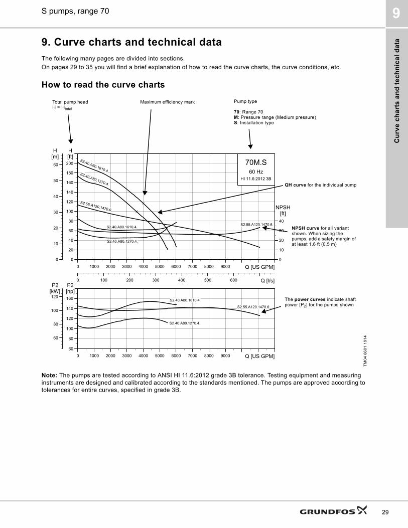
9. Curve charts and technical data
The following many pages are divided into sections.On pages 29 to 35 you will find a brief explanation of how to read the curve charts, the curve conditions, etc.
How to read the curve charts
Note: The pumps are tested according to ANSI HI 11.6:2012 grade 3B tolerance. Testing equipment and measuring instruments are designed and calibrated according to the standards mentioned. The pumps are approved according to tolerances for entire curves, specified in grade 3B.
TM04
660
1 19
14
0 1000 2000 3000 4000 5000 6000 7000 8000 9000 Q [US GPM]0
20
40
60
80
100
120
140
160
180
200[ft]H
0 100 200 300 400 500 600 Q [l/s]
0
10
20
30
40
50
60
[m]H
0
10
20
30
40
[ft]NPSH
70M.S60 Hz
HI 11.6:2012 3B
S2.55.A120.1470.6.
S2.40.A80.1270.4.
S2.40.A80.1610.4.
S2.55.A120.1470.6.
S2.40.A80.1270.4.
S2.40.A80.1610.4.
0 1000 2000 3000 4000 5000 6000 7000 8000 9000 Q [US GPM]60
80
100
120
140
160[hp]P2
60
80
100
120[kW]P2
S2.55.A120.1470.6.
S2.40.A80.1270.4.
S2.40.A80.1610.4.
Total pump headH = Htotal
Maximum efficiency mark Pump type
70: Range 70M: Pressure range (Medium pressure)S: Installation type
QH curve for the individual pump
NPSH curve for all variant shown. When sizing the pumps, add a safety margin of at least 1.6 ft (0.5 m)
The power curves indicate shaft power [P2] for the pumps shown
29

Cu
rve
ch
arts
an
d te
ch
nic
al d
ata
S pumps, range 709
30
Curve conditionsThe guidelines below apply to the curves shown in the performance charts on page 36.• ANSI-HI centrifugal pump test 11.6:2012,
acceptance level 3B.• The curves show pump performance with different
impeller diameters at rated speed.• The curves apply to the pumping of airless water at
a temperature of 68 °F (20 °C) and a kinematic viscosity of 1 cSt (1 mm2/s).
• NPSH: The curves show average values measured under the same conditions as the performance curves.When sizing the pump, add a safety margin of at least 1.6 ft (0.5 m).
• In case of densities other than 133.5 ounces/gallon (1000 kg/m3), the outlet pressure is proportional to the density.
• When pumping liquids with a density higher than 133.5 ounces/gallon (1000 kg/m3), motors with correspondingly higher outputs must be used.
Calculation of total head
The total pump head consists of the height difference between the measuring points + the differential head + the dynamic head.
Pump performance testingS pump testers are all capable of performing hydraulic performance tests according to ANSI HI 11.6:2012 requirements.ANSI HI 11.6:2012 sets standards for "rotodynamic pumps, Hydraulic performance acceptance tests, Grades 1, 2 and 3".
Performance acceptance gradesSix-pump-performance-test acceptance grades, 3B, 2B, 2U, 1B and 1U are defined in ANSI HI 11.6:2012.
These tolerance grades can be used in the contract between the pump manufacturer and the customer, or they can be used as part of a default tolerance factor for cases in which no specific tolerance grade has been agreed between the manufacturer and the customer.The performance acceptance grades are explained in Specifying acceptance grades, page 35, showing the performance grades related to an ordinary pump curve.
Hgeo: Height difference between measuring points.Hstat: Differential head between the inlet and outlet
side of the pump.Hdyn: Calculated values based on the velocity of the
pumped liquid on the inlet and outlet side of the pump.
Htotal Hgeo Hstat Hdyn+ +=
Acceptance grade
Mandatory measurements
Optional measurements
Q H P1 Eta-tot
3B ± 9 % ± 7 % + 9 % - 7 %2B ± 8 % ± 5 % + 8 %
- 5 %2U + 16 % + 10 % + 16 %1B ± 5 % ± 3 % + 4 % - 3 %1U + 10 % + 6 % + 10 % ≥ 0 %

Cu
rve
ch
art
s a
nd
te
ch
nic
al
da
ta
S pumps, range 70 9
The guarantee pointAccording to ANSI HI 11.6:2012 the acceptance-grade tolerance applies to one guarantee point.A guarantee point is defined by a guaranteed flow rate and a guaranteed head.In addition, either minimum total efficiency or maximum total input power may be guaranteed at the specified conditions.This means that the standard sets guidelines for a duty point guaranteed for the following:
– Q and H, or– Q, H and total efficiency (Eta-total), or– Q, H and total consumed power (P1).
The guarantee point is defined by a minimum of five measured test points.Example of a duty point test living up to ANSI HI 11.6:2012 requirements
Fig. 20 Five measured test points are used to verify one guarantee point
Evaluation of performanceThe test must show that the measured pump curve touches or passes through a tolerance surrounding the guarantee point, as defined by the selected acceptance grade.Guarantee-point evaluation must be made at the rated speed, which for S pumps means 50 Hz or 60 Hz.
Fig. 21 Pump curves that either pass or fail to cross the tolerance cross of the guarantee point
Performance-test types for end-suction pumpsTwo types of performance tests are available for S pumps:• duty-point-verification test• curve test.
Tests carried out on S pumps
– Tests are saved for at least five years and can be traced using the pump’s unique serial number.
– It is not possible to change acceptance grade on an already tested and supplied pump; if required, a re-test of the pump is needed.
– Witness testing can be arranged.
Duty-point-verification test, Grades 3B, 2B, 2U, 1B and 1U
This test method offers the possibility to perform a duty-point verification of the following:
– Q and H, or– Q, H and total efficiency (Eta-tot), or– Q, H and total consumed power (P1).
What Grundfos is able to guarantee for the different acceptance grades will be evaluated on a case-by-case basis. Contact your local sales company on this. Grundfos makes duty-point verification according to ANSI HI 11.6:2012 for one guarantee point at full speed, 50 or 60 Hz. The customer must tell Grundfos which duty point to verify.The requested duty point is verified by five measured points.
TM07
044
8 51
17TM
07 1
544
1818
18
20
16
14
12
10
8
6
4
2
00 20 40 60 80 100 120 140 160
H [ft]
Q [US GPM]
Head
FlowQ-guaranteed
H-guaranteed
Pass
Pass
Pass
Fail
Fail
Acceptance grade
Mandatory measurements
Optional measurements
Q H P1 Eta-tot
3B Standard On request2B
On request On request2U1B
On request On request1U
31

Cu
rve
ch
arts
an
d te
ch
nic
al d
ata
S pumps, range 709
32
Grade 1U duty-point verification
The following example illustrates performance testing according to Grade 1U. Flow and head are mandatory, and efficiency or power consumption, P1, is optional.Tolerances for a Grade 1U test are as follows:
– Flow: 10 %– Head: 6 %– Efficiency: 0 %, only equal to or better than the
guaranteed value– P1: 10 %
1. Q, H and Eta-tot are tested and verified
Fig. 22 Measured values for flow rate and head
Fig. 23 Measured values for total efficiency
2. Q, H and P1 tested and verified
Fig. 24 Measured values for flow rate and head
Fig. 25 performance range
Note that other points than the guarantee point can be measured and displayed in a curve-test report according to Grade 3B tolerances.
TM07
154
2 16
18TM
07 1
543
1618
00
2
4
6
8
10
12
14
16
18
20
200 400 600 800 1000 1200
H [ft]
Q [US GPM]
00
10
20
30
40
50
60
70
80
200 400 600 800 1000 1200
Eta-tot % [ft]
Q [US GPM]TM
07 1
542
1618
TM07
154
5 16
18
00
2
4
6
8
10
12
14
16
18
20
200 400 600 800 1000 1200
H [ft]
Q [US GPM]
00
2
4
6
8
10
12
14
16
18
20
200 400 600 800 1000 1200
P1 [HP]
Q [US GPM]

Cu
rve
ch
art
s a
nd
te
ch
nic
al
da
ta
S pumps, range 70 9
Curve test, Grade 3BThis test method is developed by Grundfos and is based on ANSI HI 11.6:2012 performance acceptance grade 3B tolerances: Q = ± 9 %, H = ± 7 %.
Fig. 26 Q-H curve with tolerance crosses on complete performance range
In fig. 26, tolerance crosses according to Grade 3B have been distributed across the complete performance range of a pump. We generate the upper and lower limit of the performance curve by drawing two curves at the outlines of these crosses.When the pump is tested, and the measured point is located within the range between the upper and lower limit, it meets the ANSI HI 11.6:2012 Grade 3B tolerances. This way of qualifying the pump performance is stricter than a duty-point-verification test for Grade 3B.
How does Grundfos perform curve testing for S pumpsGrundfos applies two types of curve tests:• a reference curve test• a performance curve test.
Reference curve test, Grade 3B
A reference curve test is performed when no curve test report is specified with the order. Three or four test points are measured depending on production site, and no curve test report is supplied with the pump.Measurements are made to maintain and observe continuous quality and to ensure that the supplied pump is within test grade tolerances. Test grade tolerances are set as for Grade 3B but without certification.
Example of a reference curve test
Fig. 27 Measured values for tested pump
Fig. 28 The values in fig. 27 calculated to reference speed for comparison to a reference performance curve
If a pump performance report is requested at a later stage, only reference test data are available.
Performance curve test, grade 3B
A performance curve test is carried out when a curve test report is specified with the order.The pump is tested at pre-specified flow rates, and test grade tolerances are set as for Grade 3B but without certification.
TM07
151
5 16
18
Q [US GPM]
H [ft]
TM07
167
5 20
18TM
07 1
694
2018
0 3725 Q [US GPM]
0
20
40
60
80
100
120
140
160
180
200
220
240
[ft]H
0
20
40
60
80
100
120
140
160
180
200
220
240
[hp]P1
0 3725 Q [US GPM]0
20
40
60
80
100
120
140
160
180
200
220
240
[ft]H
0
20
40
60
80
100
120
140
160
180
200
220
240
[hp]P1
33

Cu
rve
ch
arts
an
d te
ch
nic
al d
ata
S pumps, range 709
34
Example of an S pump curve test
Fig. 29 Measured values for tested pump
Fig. 30 The values in fig. 29 calculated to a reference speed for comparison to a reference performance
If the customer requires more points on the curve to be checked, individual measurements must be made, which is not part of the performance curve test.
Static high pressure test
All produced pumps undergo a static high pressure test of 1.5 x PN (nominal pressure of the pump).
Specifying acceptance gradesThe graphs in the table on page 35 show the tolerances as stated in the standard, related to an ordinary pump curve. The graphs also show which pump performance to expect if the customer, having the same pump to start with, orders a pump with the same guarantee point for different tolerances (B or U) within the acceptance grades.In some cases, it will not be possible to fulfil the same guarantee point for a unilateral tolerance as it will for a bilateral tolerance. This is indicated by the lower curve for "U" grades.If the requested guarantee point is the same for a Grade U pump as for a Grade B pump, the consequence of the production tolerances could be that a larger pump is required to obtain the requested duty point.What Grundfos is able to guarantee for the different acceptance grades will be evaluated on a case-by-case basis. Contact your local sales company on this.
TM07
167
5 20
18TM
07 1
694
2018
0 3725 Q [US GPM]
0
20
40
60
80
100
120
140
160
180
200
220
240
[ft]H
0
20
40
60
80
100
120
140
160
180
200
220
240
[hp]P1
0 3725 Q [US GPM]0
20
40
60
80
100
120
140
160
180
200
220
240
[ft]H
0
20
40
60
80
100
120
140
160
180
200
220
240
[hp]P1

Cu
rve
ch
art
s a
nd
te
ch
nic
al
da
ta
S pumps, range 70 9
Acceptance grades and tolerances
Acceptance grade B
This acceptance grade refers to grades with a bilateral tolerance on flow rate and head and with a tolerance on efficiency.
Acceptance grade U
This acceptance grade refers to a grade with a unilateral tolerance on flow rate and head. For the 2U grade, there is a tolerance on efficiency. For the 1U grade, there is no tolerance on efficiency.Note that if the acceptance grade changes from Grade 1B to 1U, the customer does not necessarily get a better pump with a higher efficiency. More likely, he gets a pump where the performance is always to the positive side of the guarantee point.
CertificatesCertificates have to be confirmed for every order and are available on request as follows:• certificate of compliance with the order (EN
10204-2.1)• pump test sheet.
Witness testWhen the pumps are being tested or are tested with a certification, it is possible for the customer to witness the testing procedure according to ANSI HI 11.6:2012.The witness test is not a certificate and will not result in a written statement from Grundfos. The witness itself is the only guarantee that everything is carried out as prescribed in the testing procedure.If the customer wants to witness the test, place this request on the order.
Acceptance grade
B U
Gra
de
3G
rad
e 2
H: ±7%
: 7%
Q: ±9%
H
Q
Q
H: ±5%
Q: ±8%
: 5%
Q
H
Q
H: +10%
Q: +16%
: 5%
Q
H
Q
Gra
de
1
Acceptance grade
B U
H: ±3%
Q: ±5%
: 3%
Q
H
Q
H: +6%
Q: +10%
: 0%
Q
H
Q
35

Pe
rform
an
ce
cu
rve
s a
nd
tec
hn
ica
l da
ta
10
36
10. Performance curves and technical data
Low pressure
S3.45.A200.1070.8 and S3.45.A200.1880.6
TM04
659
9 19
14
3000 4000 5000 6000 7000 8000 9000 10000 11000 12000 13000 14000 Q [US GPM]0
10
20
30
40
50
60
70
80
[ft]H
200 300 400 500 600 700 800 900 Q [l/s]
0
5
10
15
20
25[m]H
0
10
20
30
40
[ft]NPSH
70L.S60 Hz
HI 11.6:2012 3B
S3.45.A200.1880.6.
S3.45.A200.1070.8.
S3.45.A200.1880.6.
S3.45.A200.1070.8.
3000 4000 5000 6000 7000 8000 9000 10000 11000 12000 13000 14000 Q [US GPM]0
50
100
150
200
[hp]P2
0
50
100
150
[kW]P2
S3.45.A200.1880.6.
S3.45.A200.1070.8.

Pe
rfo
rma
nc
e c
urv
es
an
d t
ec
hn
ica
l d
ata
10
Motor data
Note: Enclosure class: IP68
Pump data
* Applies to material code G (see Type key). For other material codes, please contact Grundfos.S
TM04
660
0 19
14
Pump typeP1 P2
No. of poles
RPMStarting method
IN Istart ηmotor [%] Cos φ Moment of inertia
[lbft2 (kgm2)]
Breakdown torque Mmax [lbf*ft (Nm)][HP (kW)] [A] [A] 1/2 3/4 1/1 1/2 3/4 1/1
S3.45.A200.1880.6.70L 206(154)
188(140) 6 1186 Y/D 246 1978 89 90 91 0.62 0.72 0.78 66.4 (2.80) 2161.0 (2930)
S3.45.A200.1070.8.70L 115(86)
107(80) 8 882 Y/D 129 861 93 94 93 0.77 0.83 0.84 49.8 (2.10) 1600.5 (2170)
Pump typeImpeller diameter Maximum solids size Pump housing pressure
Maximum installation depth
Moment of inertia*
[inch (mm)] [inch (mm)] [PSI (PN)] [ft (m)] [lbft2 (kgm2)]
S3.45.A200.1880.6.70L.S/C/D/H.371 14.6 (371)4.5 (115) 145 (10) 66 (20)
33.86 (1.427)S3.45.A200.1070.8.70L.S/C/D/H.404 15.9 (404)
3000 4000 5000 6000 7000 8000 9000 10000 11000 12000 13000 14000 Q [US GPM]0
10
20
30
40
50
60
70
80
[ft]H
200 300 400 500 600 700 800 900 Q [l/s]
0
5
10
15
20
25[m]H
0
10
20
30
40
[ft]NPSH
70L.C/D/H60 Hz
HI 11.6:2012 3B
S3.45.A200.1880.6.
S3.45.A200.1070.8.
S3.45.A200.1880.6.
S3.45.A200.1070.8.
3000 4000 5000 6000 7000 8000 9000 10000 11000 12000 13000 14000 Q [US GPM]0
50
100
150
200
[hp]P2
0
50
100
150
[kW]P2
S3.45.A200.1880.6.
S3.45.A200.1070.8.
37

Pe
rform
an
ce
cu
rve
s a
nd
tec
hn
ica
l da
ta
10
38
Medium pressure
S2.40.A80.1270.4, S2.55.A120.1470.6 and S2.40.A80.1610.4
TM04
660
1 19
14
0 1000 2000 3000 4000 5000 6000 7000 8000 9000 Q [US GPM]0
20
40
60
80
100
120
140
160
180
200[ft]H
0 100 200 300 400 500 600 Q [l/s]
0
10
20
30
40
50
60
[m]H
0
10
20
30
40
[ft]NPSH
70M.S60 Hz
HI 11.6:2012 3B
S2.55.A120.1470.6.
S2.40.A80.1270.4.
S2.40.A80.1610.4.
S2.55.A120.1470.6.
S2.40.A80.1270.4.
S2.40.A80.1610.4.
0 1000 2000 3000 4000 5000 6000 7000 8000 9000 Q [US GPM]60
80
100
120
140
160[hp]P2
60
80
100
120[kW]P2
S2.55.A120.1470.6.
S2.40.A80.1270.4.
S2.40.A80.1610.4.

Pe
rfo
rma
nc
e c
urv
es
an
d t
ec
hn
ica
l d
ata
10
Motor data
Note: Enclosure class: IP68
Pump data
* Applies to material code G (see Type key). For other material codes, please contact Grundfos.
TM04
660
2 19
14
Pump typeP1 P2
No. of poles
RPMStarting method
IN Istart ηmotor [%] Cos φ Moment of inertia
[lbft2 (kgm2)]
Breakdown torque Mmax [lbf*ft (Nm)][HP (kW)] [A] [A] 1/2 3/4 1/1 1/2 3/4 1/1
S2.40.A80.1270.4.70M 138(103)
127(95) 4 1778 Y/D 148 1105 94 94 92 0.80 0.86 0.88 20.2 (0.85) 1090.9 (1479)
S2.40.A80.1610.4.70M 174(130)
161(120) 4 1778 Y/D 195 1380 94 94 92 0.77 0.84 0.84 26.1 (1.10) 1427.2 (1935)
S2.55.A120.1470.6.70M 158(118)
147(110) 6 1181 Y/D 175 1275 91 93 93 0.73 0.81 0.85 49.8 (2.10) 1639.6 (2223)
Pump typeImpeller diameter Maximum solids size
Pump housing pressure
Maximum installation depth
Moment of inertia*
[inch (mm)] [inch (mm)] [PSI (PN)] [ft (m)] [lbft2 (kgm2)]
S2.40.A80.1270.4.70M.S/C/D/H.332 13.1 (332)4.0 (100)
145 (10) 66 (20)13.24 (0.558)
S2.40.A80.1610.4.70M.S/C/D/H.355 14.0 (355) 15.87 (0.669)S2.55.A120.1470.6.70M.S/C/D/H.420 16.5 (420) 5.5 (140) 28.56 (1.204)
0 1000 2000 3000 4000 5000 6000 7000 8000 9000 Q [US GPM]0
20
40
60
80
100
120
140
160
180
200[ft]H
0 100 200 300 400 500 600 Q [l/s]
0
10
20
30
40
50
60
[m]H
0
10
20
30
40
[ft]NPSH
70M.C/D/H60 Hz
HI 11.6:2012 3B
S2.55.A120.1470.6.
S2.40.A80.1270.4.
S2.40.A80.1610.4.
S2.55.A120.1470.6.
S2.40.A80.1270.4.
S2.40.A80.1610.4.
0 1000 2000 3000 4000 5000 6000 7000 8000 9000 Q [US GPM]60
80
100
120
140
160[hp]P2
60
80
100
120[kW]P2
S2.55.A120.1470.6.
S2.40.A80.1270.4.
S2.40.A80.1610.4.
39

Pe
rform
an
ce
cu
rve
s a
nd
tec
hn
ica
l da
ta
10
40
S3.45.A120.1070.8 and S3.45.A120.1880.8
TM04
660
3 19
14
0 1000 2000 3000 4000 5000 6000 7000 8000 9000 10000 Q [US GPM]0
10
20
30
40
50
60
70
80
90
100[ft]H
0 100 200 300 400 500 600 700 Q [l/s]
0
5
10
15
20
25
30
[m]H
0
10
20
30
40
[ft]NPSH
70M.S60 Hz
HI 11.6:2012 3B
S3.45.A120.1880.6.
S3.45.A120.1070.8.
S3.45.A120.1880.6.
S3.45.A120.1070.8.
0 1000 2000 3000 4000 5000 6000 7000 8000 9000 10000 Q [US GPM]60
80
100
120
140
160
180[hp]P2
60
80
100
120
[kW]P2
S3.45.A120.1880.6.
S3.45.A120.1070.8.

Pe
rfo
rma
nc
e c
urv
es
an
d t
ec
hn
ica
l d
ata
10
Motor data
Note: Enclosure class: IP68
Pump data
* Applies to material code G (see Type key). For other material codes, please contact Grundfos.
TM04
660
4 19
14
Pump typeP1 P2
No. of poles
RPMStarting method
IN Istart ηmotor [%] Cos φ Moment of inertia
[lbft2 (kgm2)]
Breakdown torque Mmax [lbf*ft (Nm)][HP (kW)] [A] [A] 1/2 3/4 1/1 1/2 3/4 1/1
S3.45.A120.1880.6.70M 206(154)
188(140) 6 1186 Y/D 246 1978 89 90 91 0.62 0.72 0.78 66.4 (2.80) 2161.0 (2930)
S3.45.A120.1070.8.70M 115(86)
107(80) 8 882 Y/D 129 861 93 94 93 0.77 0.83 0.84 49.8 (2.10) 1600.5 (2170)
Pump typeImpeller diameter Maximum solids size Pump housing pressure
Maximum installation depth
Moment of inertia*
[inch (mm)] [inch (mm)] [PSI (PN)] [ft (m)] [lbft2 (kgm2)]
S3.45.A120.1880.6.70M.S/C/D/H.407 16.0 (407)4.5 (115) 145 (10) 66 (20)
27.88 (1.175)S3.45.A120.1070.8.70M.S/C/D/H.442 17.4 (442) 34.77 (1.465)
0 1000 2000 3000 4000 5000 6000 7000 8000 9000 10000 Q [US GPM]0
10
20
30
40
50
60
70
80
90
100[ft]H
0 100 200 300 400 500 600 700 Q [l/s]
0
5
10
15
20
25
30
[m]H
0
10
20
30
40
[ft]NPSH
70M.C/D/H60 Hz
HI 11.6:2012 3B
S3.120.300.1400.6.
S3.120.300.800.8.
S3.120.300.1400.6.
S3.120.300.800.8.
0 1000 2000 3000 4000 5000 6000 7000 8000 9000 10000 Q [US GPM]60
80
100
120
140
160
180[hp]P2
60
80
100
120
[kW]P2
S3.120.300.1400.6.
S3.120.300.800.8.
41
Pe
rform
an
ce
cu
rve
s a
nd
tec
hn
ica
l da
ta
10
42
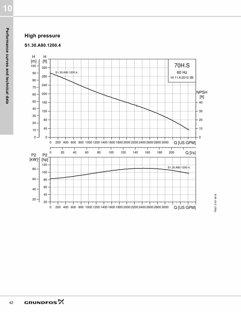
High pressure
S1.30.A80.1200.4
TM07
319
7 48
18
0 200 400 600 800 1000 1200 1400 1600 1800 2000 2200 2400 2600 2800 3000 Q [US GPM]
0
40
80
120
160
200
240
280
320
[ft]H
0 20 40 60 80 100 120 140 160 180 200 Q [l/s]
0
10
20
30
40
50
60
70
80
90
100[m]H
0
10
20
30
40
[ft]NPSH
70H.S60 Hz
HI 11.6:2012 3B
S1.30.A80.1200.4.
0 200 400 600 800 1000 1200 1400 1600 1800 2000 2200 2400 2600 2800 3000 Q [US GPM]
20
40
60
80
100
120
[hp]P2
20
40
60
80
[kW]P2
S1.30.A80.1200.4.

Pe
rfo
rma
nc
e c
urv
es
an
d t
ec
hn
ica
l d
ata
10
Motor data
Note: Enclosure class: IP68
Pump data
* Applies to material code G (see Type key). For other material codes, please contact Grundfos.
TM07
319
8 48
18
Pump typeP1 P2
No. of poles
RPMStarting method
IN Istart ηmotor [%] Cos φ Moment of inertia
[lbft2 (kgm2)]
Breakdown torque Mmax [lbf*ft (Nm)][HP (kW)] [A] [A] 1/2 3/4 1/1 1/2 3/4 1/1
S1.30.A80.1200.4.70H 4 Y/D
Pump typeImpeller diameter Maximum solids size
Pump housing pressure
Maximum installation depth
Moment of inertia*
[inch (mm)] [inch (mm)] [PSI (PN)] [ft (m)] [lbft2 (kgm2)]
S1.30.A80.1200.4.70H.S/C/D/H.408 16.1 (408) 3 (80) 145 (10) 66 (20) 24.2 (1.02)
0 200 400 600 800 1000 1200 1400 1600 1800 2000 2200 2400 2600 2800 3000 3200Q [US GPM]
0
40
80
120
160
200
240
280
320
[ft]H
0 20 40 60 80 100 120 140 160 180 200 220Q [l/s]
0
10
20
30
40
50
60
70
80
90
100[m]H
0
10
20
30
40
[ft]NPSH
70H.C/D/H60 Hz
HI 11.6:2012 3B
S1.80.200.900.4.
0 200 400 600 800 1000 1200 1400 1600 1800 2000 2200 2400 2600 2800 3000 3200Q [US GPM]
20
40
60
80
100
120
[hp]P2
20
40
60
80
[kW]P2
S1.80.200.900.4.
43

Pe
rform
an
ce
cu
rve
s a
nd
tec
hn
ica
l da
ta
10
44
S2.35.A80.1270.4 and S2.35.A80.1610.4
TM04
659
5 01
914
0 400 800 1200 1600 2000 2400 2800 Q [US GPM]0
40
80
120
160
200
240
280
[ft]H
0 50 100 150 200 Q [l/s]
0
20
40
60
80
[m]H
0
10
20
30
40
[ft]NPSH
70H.S60 Hz
HI 11.6:2012 3B
S2.35.A80.1270.4.
S2.35.A80.1610.4.
S2.35.A80.1270.4.
S2.35.A80.1610.4.
0 400 800 1200 1600 2000 2400 2800 Q [US GPM]0
50
100
150
200
[hp]P2
0
50
100
150
[kW]P2
S2.35.A80.1270.4.
S2.35.A80.1610.4.

Pe
rfo
rma
nc
e c
urv
es
an
d t
ec
hn
ica
l d
ata
10
Motor data
Note: Enclosure class: IP68
Pump data
* Applies to material code G (see Type key). For other material codes, please contact Grundfos.
TM04
659
6 19
14
Pump typeP1 P2
No. of poles
RPMStarting method
IN Istart ηmotor [%] Cos φ Moment of inertia
[lbft2 (kgm2)]
Breakdown torque Mmax [lbf*ft (Nm)][HP (kW)] [A] [A] 1/2 3/4 1/1 1/2 3/4 1/1
S2.35.A80.1270.4.70H 138(103)
127(95) 4 1778 Y/D 148 1105 94 94 92 0.80 0.86 0.88 20.2 (0.85) 1090.9 (1479)
S2.35.A80.1610.4.70H 174(130)
161(120) 4 1777 Y/D 195 1380 94 94 92 0.77 0.84 0.84 26.1 (1.10) 1427.2 (1935)
Pump typeImpeller diameter Maximum solids size Pump housing pressure Moment of inertia*
[inch (mm)] [inch (mm)] [PSI (PN)] [lbft2 (kgm2)]
S2.35.A80.1270.4.70H.S/C/D/H.340 13.4 (340)3.5 (90) 145 (10)
13.31 (0.561)S2.35.A80.1610.4.70H.S/C/D/H.361 14.2 (361) 14.26 (0.601)
0 400 800 1200 1600 2000 2400 2800 Q [US GPM]0
40
80
120
160
200
240
280
[ft]H
0 50 100 150 200 Q [l/s]
0
20
40
60
80
[m]H
0
10
20
30
40
[ft]NPSH
70H.C/D/H60 Hz
HI 11.6:2012 3B
S2.35.A80.1270.4.
S2.35.A80.1610.4.
S2.35.A80.1270.4.
S2.35.A80.1610.4.
0 400 800 1200 1600 2000 2400 2800 Q [US GPM]0
50
100
150
200
[hp]P2
0
50
100
150
[kW]P2
S2.35.A80.1270.4.
S2.35.A80.1610.4.
45

Pe
rform
an
ce
cu
rve
s a
nd
tec
hn
ica
l da
ta
10
46
S2.40.A100.1070.8, S2.45.A100.1470.6 and S2.45.A100.1880.6
TM04
659
7 48
18
0 500 1000 1500 2000 2500 3000 3500 4000 4500 5000 5500 6000 6500 7000Q [US GPM]
0
20
40
60
80
100
120
140
160
[ft]H
0 50 100 150 200 250 300 350 400 450 Q [l/s]
0
10
20
30
40
50[m]H
0
10
20
30
40
[ft]NPSH
70H.S60 Hz
HI 11.6:2012 3B
S2.40.A100.1070.8.
S2.45.A100.1470.6.
S2.45.A100.1880.6.
S2.40.A100.1070.8.
S2.45.A100.1470.6.
S2.45.A100.1880.6.
0 500 1000 1500 2000 2500 3000 3500 4000 4500 5000 5500 6000 6500 7000Q [US GPM]
0
50
100
150
200
[hp]P2
0
50
100
150
[kW]P2
S2.40.A100.1070.8.
S2.45.A100.1470.6.
S2.45.A100.1880.6.

Pe
rfo
rma
nc
e c
urv
es
an
d t
ec
hn
ica
l d
ata
10
Motor data
Note: Enclosure class: IP68
Pump data
* Applies to material code G (see Type key). For other material codes, please contact Grundfos.
TM04
659
8 48
18
Pump typeP1 P2
No. of poles
RPMStarting method
IN Istart ηmotor [%] Cos φ Moment of inertia
[lbft2 (kgm2)]
Breakdown torque Mmax [lbf*ft (Nm)][HP (kW)] [A] [A] 1/2 3/4 1/1 1/2 3/4 1/1
S2.45.A100.1470.6.70H 158(118)
147(110) 6 1181 Y/D 175 1275 91 93 93 0.73 0.81 0.85 49.8 (2.10) 1639.6 (2223)
S2.45.A100.1880.6.70H 206(154)
188(140) 6 1186 Y/D 246 1978 89 90 91 0.62 0.72 0.78 66.4 (2.80) 2162.1 (2930)
S2.40.A100.1070.8.70H 115(86)
107(80) 8 882 Y/D 129 861 93 94 93 0.77 0.83 0.84 49.8 (2.10) 1600.5 (2170)
Pump typeImpeller diameter Maximum solids size
Pump housing pressure
Maximum installation depth
Moment of inertia*
[inch (mm)] [inch (mm)] [PSI (PN)] [ft (m)] [lbft2 (kgm2)]
S2.45.A100.1470.6.70H.S/C/D/H.443 17.5 (443)4.5 (115)
145 (10) 66 (20)36.66 (1.545)
S2.45.A100.1880.6.70H.S/C/D/H.465 18.3 (465) 42.07 (1.773)S2.40.A100.1070.8.70H.S/C/D/H.523 20.6 (523) 4.0 (100) 60.04 (2.53)
0 500 1000 1500 2000 2500 3000 3500 4000 4500 5000 5500 6000 6500 7000Q [US GPM]
0
20
40
60
80
100
120
140
160
[ft]H
0 50 100 150 200 250 300 350 400 450 Q [l/s]
0
10
20
30
40
50[m]H
0
10
20
30
40
[ft]NPSH
70H.C/D/H60 Hz
HI 11.6:2012 3B
S2.40.A100.1070.8.
S2.45.A100.1470.6.
S2.45.A100.1880.6.
S2.40.A100.1070.8.
S2.45.A100.1470.6.
S2.45.A100.1880.6.
0 500 1000 1500 2000 2500 3000 3500 4000 4500 5000 5500 6000 6500 7000Q [US GPM]
0
50
100
150
200
[hp]P2
0
50
100
150
[kW]P2
S2.40.A100.1070.8.
S2.45.A100.1470.6.
S2.45.A100.1880.6.
47
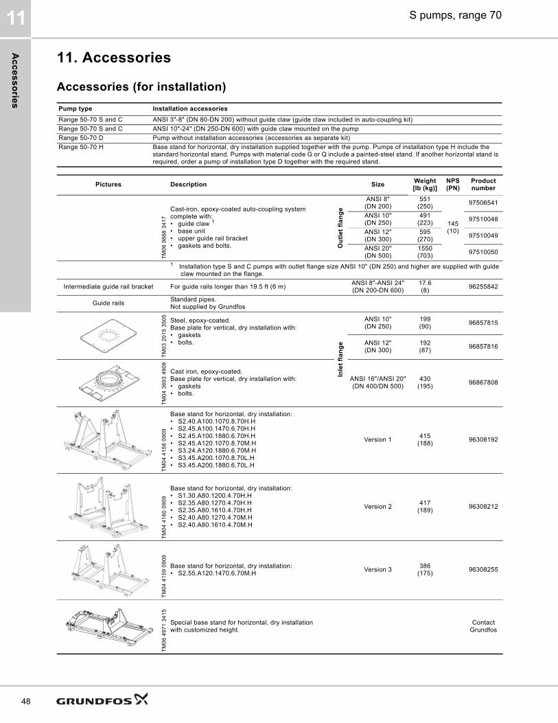
Ac
ce
ss
orie
s
S pumps, range 7011
48
11. Accessories
Accessories (for installation)
Pump type Installation accessories
Range 50-70 S and C ANSI 3"-8" (DN 80-DN 200) without guide claw (guide claw included in auto-coupling kit)Range 50-70 S and C ANSI 10"-24" (DN 250-DN 600) with guide claw mounted on the pumpRange 50-70 D Pump without installation accessories (accessories as separate kit)Range 50-70 H Base stand for horizontal, dry installation supplied together with the pump. Pumps of installation type H include the
standard horizontal stand. Pumps with material code G or Q include a painted-steel stand. If another horizontal stand is required, order a pump of installation type D together with the required stand.
Pictures Description SizeWeight[lb (kg)]
NPS(PN)
Product number
TM06
986
8 34
17
Cast-iron, epoxy-coated auto-coupling system complete with:• guide claw 1• base unit• upper guide rail bracket• gaskets and bolts. O
utl
et
fla
ng
e
ANSI 8" (DN 200)
551(250)
145(10)
97506541
ANSI 10"(DN 250)
491(223) 97510048
ANSI 12" (DN 300)
595(270) 97510049
ANSI 20"(DN 500)
1550(703) 97510050
1 Installation type S and C pumps with outlet flange size ANSI 10" (DN 250) and higher are supplied with guide claw mounted on the flange.
Intermediate guide rail bracket For guide rails longer than 19.5 ft (6 m) ANSI 8"-ANSI 24"(DN 200-DN 600)
17.6(8) 96255842
Guide rails Standard pipes. Not supplied by Grundfos
TM03
201
5 35
05 Steel, epoxy-coated.Base plate for vertical, dry installation with:• gaskets• bolts.
Inle
t fl
an
ge
ANSI 10"(DN 250)
199(90) 96857815
ANSI 12" (DN 300)
192(87) 96857816
TM04
369
3 49
08
Cast iron, epoxy-coated.Base plate for vertical, dry installation with:• gaskets• bolts.
ANSI 16"/ANSI 20"(DN 400/DN 500)
430(195) 96867808
TM04
415
8 09
09
Base stand for horizontal, dry installation:• S2.40.A100.1070.8.70H.H• S2.45.A100.1470.6.70H.H• S2.45.A100.1880.6.70H.H• S2.45.A120.1070.8.70M.H• S3.24.A120.1880.6.70M.H• S3.45.A200.1070.8.70L.H• S3.45.A200.1880.6.70L.H
Version 1 415(188) 96308192
TM04
416
0 09
09
Base stand for horizontal, dry installation:• S1.30.A80.1200.4.70H.H• S2.35.A80.1270.4.70H.H• S2.35.A80.1610.4.70H.H• S2.40.A80.1270.4.70M.H• S2.40.A80.1610.4.70M.H
Version 2 417(189) 96308212
TM04
415
9 09
09
Base stand for horizontal, dry installation:• S2.55.A120.1470.6.70M.H Version 3 386
(175) 96308255
TM06
497
1 34
15
Special base stand for horizontal, dry installationwith customized height.
Contact Grundfos

Ac
ce
ss
ori
es
S pumps, range 70 11
Other accessories
Picture Description SizeProduct number
TM02
612
6 51
02
Galvanized lifting chain with lifting link and safety hook. Certified. Maximum lifting capacity 7055 lb (3200 kg).
13 ft (4 m) 98425788
20 ft (6 m) 98425789
26 ft (8 m) 98425790
33 ft (10 m) 98425791
Stainless steel lifting chain with lifting link and safety hook. Certified. Maximum lifting capacity 7055 lb (3200 kg).
13 ft (4 m) 98425805
20 ft (6 m) 98425806
26 ft (8 m) 98425807
33 ft (10 m) 98425808
49
Dim
en
sio
ns
S pumps, range 7012
50
12. Dimensions
Recommendation for pump foundationsNote: This applies only to pumps above 20 HP (15 kW).All rotating equipment generates vibrations as a mass, such as an impeller or rotor, is turning at high speeds. Proper installation and anchorage of Grundfos pumps and installation accessories is critical to limit vibrations and achieve reliable, trouble-free installation. It is important to note that all mechanically connected pipes, fittings and supports to the pump are part of a single system.The rotating mass of the entire pump together with the forces from the motor and hydraulics will generate disturbances related to the speed of the motor. Unbalance and impeller vane pass in hydraulics are the two most important frequencies affecting vibration. When these frequencies coincide with the natural frequency of the entire mechanical system, the vibration level will increase substantially.Pumps from Grundfos are designed and produced according to the highest quality standards. The method and grade of balancing is specified by the manufacturer in order to achieve acceptable vibration levels. Although the pump itself can withstand rather high vibration levels under operating conditions without considerable lifetime reduction, the pipes and supportive structure might suffer and crack if vibration levels are too high. Furthermore, noticeable noise levels might be generated.The likelihood of high vibration levels occurring is increased in variable-speed applications where the pump is operated over a range of speeds rather than a single constant speed. Most variable-speed drives provide the possibility to exclude certain frequency ranges to avoid operating areas with high vibrations.To ensure acceptable vibration levels in the field, all parts of the system must be sufficiently stiff and firmly anchored to minimize vibrations:• The foundation and concrete must be of adequate
strength to support the weight of the pump including accessories, the weight of the liquid passing through the pump, and the forces generated by the pump
• As a rule of thumb, the mass of the concrete foundation must be a minimum of three to five times the mass of the supported equipment and must have sufficient rigidity to withstand the axial, transverse, and torsional loadings generated by the equipment.
• The foundation must be 6" (15 cm) wider than the base plate for pumps up to 470 HP (350 kW) and 10" (25 cm) wider for larger pumps.
• The concrete used in the foundation must have a minimum tensile strength of 363 PSI (250 N/cm2).Epoxy grout must always be used to secure the pump base plate to the foundation.
Pull-out strengths for anchor bolts
Submerged installation on auto-coupling (type S and C):
1 Pump outlet ANSI 5" (DN 125) and base plate outlet ANSI 6" (DN 150).
Dry installation (type H and D):
1 Base plate inlet ANSI 20" (DN 500) and pump inlet ANSI 16" (DN 400).
Auto-coupling base unit
Anchor boltsPull-out strength
[kip (kN)]
ANSI 4" (DN 100)4 x 5/8"
(4 x M16)
1.1 (5)ANSI 5"/NPS 6"(DN 125/DN 150)1 1.8 (8)
ANSI 8" (DN 200)4 x 1"
(4 x M24)
3.6 (16)ANSI 10" (DN 250) 6.8 (30)ANSI 12" (DN 300)
9.0 (40)ANSI 20" (DN 500)6 x 1 1/4" (6 x M30)ANSI 24" (DN 600)
ANSI 32" (DN 800) 4.5 (20)
Dry installation Anchor boltsPull-out strength
[kip (kN)]
ANSI 4" (DN 100) 3 x 3/4"(3 x M20)
4.0 (18)ANSI 6" (DN 150) 6 x 3/4"(6 x M20)ANSI 8" (DN 200)
ANSI 10" (DN 250)
6 x 1" (6 x M24) 5.6 (25)
ANSI 12" (DN 300)ANSI 16" (DN 400)ANSI 20"/ANSI 16"(DN500/DN400)1
ANSI 20" (DN 500)ANSI 24" (DN 600)ANSI 32" (DN 800)

Dim
en
sio
ns
S pumps, range 70 12
Basic pump
Fig. 31 Basic pumps
TM04
241
2 20
18 -
TM07
165
3 20
18
D
DC10
D01 x D1N
F
DT2
DN2
H
E
C
MOT Hfix
MOT_H
A
HYDR_HDN1
D02 x D2N
DC02
DN2
DC02
D02 x D2N
H
D
F
MOT Hfix
HYDR_H
MOT_H
A
C
E
D T 2
Installation types D and H
Installation types S and C
51

Dim
en
sio
ns
S pumps, range 7012
52
Note: Dimensions D01, D1N, DC10 and DN1 are equal to zero for installation types C and S because the inlet type.
Pump type
[inch (mm)] Pc. [inch (mm)]
A C D D01 D02 D1N D2N DC02 DC10 DN1 DN2 DT2 E F HHYDR
HMOT
HMOTHfix
S1.30.A80.1200.4.70H.C/S 64.9(1648)
42.6(1083)
11.8(300) - 0.95
(24) - 8 11.7(298) - - ANSI 8"
(DN 200)0.9(24)
31.5(800)
23.5(596)
8.7(220)
12.9(328)
52.0(1320)
0.79(20)
S1.30.A80.1200.4.70H.D/H 65.1(1654)
34.8(883)
11.8(300)
3/4"(M20)
0.95(24) 12 8 11.7
(298)14.3(362)
ANSI 10"(DN 250)
ANSI 8"(DN 200)
0.9(24)
23.6(600)
23.5(596)
8.9(226)
13.1(334)
52.0(1320)
0.79(20)
S2.35.A80.1270.4.70H.C/S 64.0(1625)
30.0(770)
11.2(285) - 0.95
(24) - 8 11.7(298) - - ANSI 8"
(DN 200)1.02(26)
19.7(500)
22.4(570)
8.0(203)
12.0(305)
53.1(1350)
0.79(20)
S2.35.A80.1270.4.70H.D/H 64.5(1638)
30.0(770)
11.2(285)
3/4"(M20)
0.95(24) 12 8 11.7
(298)14.3(362)
ANSI 10"(DN 250)
ANSI 8"(DN 200)
1.02(26)
19.7(500)
22.4(570)
8.9(226)
12.5(318)
53.1(1350)
0.79(20)
S2.35.A80.1610.4.70H.C/S 64.0(1625)
30.0(770)
11.2(285) - 0.95
(24) - 8 11.7(298) - - ANSI 8"
(DN 200)1.02(26)
19.7(500)
22.4(570)
8.0(203)
12.0(305)
53.1(1350)
0.79(20)
S2.35.A80.1610.4.70H.D/H 64.5(1638)
30.0(770)
11.2(285)
3/4"(M20)
0.95(24) 12 8 11.7
(298)14.3(362)
ANSI 10"(DN 250)
ANSI 8"(DN 200)
1.02(26)
19.7(500)
22.4(570)
8.9(226)
12.5(318)
53.1(1350)
0.79(20)
S2.40.A80.1270.4.70M.C/S 64.5(1638)
31.9(809)
15.7(400) - 0.95
(24) - 8 11.7(296) - - ANSI 8"
(DN 200)1.02(26)
18.1(460)
28.4(720)
8.5(215)
12.5(318)
53.1(1350)
0.79(20)
S2.40.A80.1270.4.70M.D/H 64.5(1638)
31.9(809)
15.7(400)
3/4"(M20)
0.95(24) 12 8 11.7
(296)14.3(362)
ANSI 10"(DN 250)
ANSI 8"(DN 200)
1.02(26)
18.1(460)
28.4(720)
8.5(215)
12.5(318)
53.1(1350)
0.79(20)
S2.40.A80.1610.4.70M.C/S 64.5(1638)
31.9(809)
15.7(400) - 0.95
(24) - 8 11.7(296) - - ANSI 8"
(DN 200)1.02(26)
18.1(460)
28.4(720)
8.5(215)
12.5(318)
53.1(1350)
0.79(20)
S2.40.A80.1610.4.70M.D/H 64.5(1638)
31.9(809)
15.7(400)
3/4"(M20)
0.95(24) 12 8 11.7
(296)14.3(362)
ANSI 10"(DN 250)
ANSI 8"(DN 200)
1.02(26)
18.1(460)
28.4(720)
8.5(215)
12.5(318)
53.1(1350)
0.79(20)
S2.40.A100.1070.8.70H.C/S 66.5(1689)
47.0(1193)
18.8(478) - 0.95
(24) - 12 14.3(362) - - ANSI 10"
(DN 250)1.18(30)
29.5(750)
35.1(891)
9.3(235)
14.5(369)
53.1(1350)
0.79(20)
S2.40.A100.1070.8.70H.D/H 70.5(1790)
47.0(1193)
18.8(478)
3/4"(M20)
0.95(24) 6 12 14.3
(362)17.0(432)
ANSI 12"(DN 300)
ANSI 10"(DN 250)
1.18(30)
29.5(750)
35.1(891)
13.2(336)
18.5(470)
53.1(1350)
0.79(20)
S2.45.A100.1470.6.70H.C/S 66.5(1689)
47.0(1193)
18.8(478) - 0.95
(24) - 12 14.3(362) - - ANSI 10"
(DN 250)1.18(30)
29.5(750)
35.1(891)
9.3(235)
14.5(369)
53.1(1350)
0.79(20)
S2.45.A100.1470.6.70H.D/H 70.5(1790)
47.0(1193)
18.8(478)
3/4"(M20)
0.95(24) 6 12 14.3
(362)17.0(432)
ANSI 12"(DN 300)
ANSI 10"(DN 250)
1.18(30)
29.5(750)
35.1(891)
13.2(336)
18.5(470)
53.1(1350)
0.79(20)
S2.45.A100.1880.6.70H.C/S 72.6(1844)
47.0(1193)
18.8(478) - 0.95
(24) - 12 14.3(362) - - ANSI 10"
(DN 250)1.18(30)
29.5(750)
35.1(891)
9.3(235)
14.5(369)
59.3(1505)
0.79(20)
S2.45.A100.1880.6.70H.D/H 76.6(1915)
47.0(1193)
18.8(478)
3/4"(M20)
0.95(24) 6 12 14.3
(362)17.0(432)
ANSI 12"(DN 300)
ANSI 10"(DN 250)
1.18(30)
29.5(750)
35.1(891)
13.2(336)
18.5(470)
59.3(1505)
0.79(20)
S2.55.A120.1470.6.70M.C/S 76.6(1915)
47.0(1193)
20.6(522) - 1.0
(25) - 12 17.0(432) - - ANSI 12"
(DN 300)1.30(33)
27.6(700)
35.7(907)
17.7(450)
23.4(595)
53.1(1350)
0.79(20)
S2.55.A120.1470.6.70M.D/H 70.5(1790)
47.0(1193)
20.6(522)
3/4"(M20)
1.0(25) 6 12 17.0
(432)17.0(432)
ANSI 12"(DN 300)
ANSI 12"(DN 300)
1.30(33)
27.6(700)
35.7(907)
12.8(325)
18.5(470)
53.1(1350)
0.79(20)
S3.45.A120.1070.8.70M.C/S 76.6(1915)
47.0(1193)
20.6(522) - 1.0
(25) - 12 17.0(432) - - ANSI 12"
(DN 300)1.30(33)
27.6(700)
35.7(907)
17.7(450)
23.4(595)
53.1(1350)
0.79(20)
S3.45.A120.1070.8.70M.D/H 70.5(1790)
47.0(1193)
20.6(522)
3/4"(M20)
1.0(25) 6 12 17.0
(432)17.0(432)
ANSI 12"(DN 300)
ANSI 12"(DN 300)
1.30(33)
27.6(700)
35.7(907)
12.8(325)
18.5(470)
53.1(1350)
0.79(20)
S3.45.A120.1880.6.70M.C/S 81.5(2070)
47.0(1193)
20.6(522) - 1.0
(25) - 12 17.0(432) - - ANSI 12"
(DN 300)1.30(33)
27.6(700)
35.7(907)
17.7(450)
23.4(595)
59.3(1505)
0.79(20)
S3.45.A120.1880.6.70M.D/H 76.6(1945)
47.0(1193)
20.6(522)
3/4"(M20)
1.0(25) 6 12 17.0
(432)17.0(432)
ANSI 12"(DN 300)
ANSI 12"(DN 300)
1.30(33)
27.6(700)
35.7(907)
12.8(325)
18.5(470)
59.3(1505)
0.79(20)
S3.45.A200.1070.8.70L.C/S 72.0(1830)
72.6(1843)
28.3(719) - 1.3
(32) - 20 25.0(635) - - ANSI 20"
(DN 500)1.46(37)
47.2(1200)
50.0(1269)
14.9(380)
20.0(510)
53.1(1350)
0.79(20)
S3.45.A200.1070.8.70L.D/H 76.8(1951)
72.6(1843)
28.3(719)
1"(M24)
1.3(32) 8 20 25.0
(635)21.3(540)
ANSI 16"(DN 400)
ANSI 20"(DN 500)
1.46(37)
47.2(1200)
50.0(1269)
18.2(461)
24.8(631)
53.1(1350)
0.79(20)
S3.45.A200.1880.6.70L.C/S 78.1(1985)
72.6(1843)
28.3(719) - 1.3
(32) - 20 25.0(635) - - ANSI 20"
(DN 500)1.46(37)
47.2(1200)
50.0(1269)
14.9(380)
20.0(510)
59.3(1505)
0.79(20)
S3.45.A200.1880.6.70L.D/H 82.9(2106)
72.6(1843)
28.3(719)
1"(M24)
1.3(32) 8 20 25.0
(635)21.3(540)
ANSI 16"(DN 400)
ANSI 20"(DN 500)
1.46(37)
47.2(1200)
50.0(1269)
18.2(461)
24.8(631)
59.3(1505)
0.79(20)

Dim
en
sio
ns
S pumps, range 70 12
Installation on auto-coupling system
Upper guide rail bracket dimensions
Fig. 32 Installation dimensions for upper guide rail bracket
Auto-coupling dimensions
Fig. 33 Dimensions for base unit
1 Six bolt installation: distance between the front bolt hole and the middle bolt hole / distance between the middle bolt hole and the back bolt hole.
TM06
991
5 36
17
Auto-couplingSize
X[inch (mm)]Product number
97506541 ANSI 8" (DN 200)
6 (150)97510048 ANSI 10" (DN 250)97510049 ANSI 12" (DN 300)97510050 ANSI 20" (DN 500)
X
TM06
649
7 15
16
B
G C
A
DE
I JH
F
K
Product number Size[inch (mm)]
A B C D E F G H I J K
97506541 ANSI 8" (DN 200) 19.0(485)
28.0(710)
14.4(365)
21.0(535)
3.5(89)
3.4(86)
6.9(175)
19.7(500)
16.9(430)
16.9(430)
27.9(710)
97510048 ANSI 10" (DN 250) 21.4(545)
29.6(753)
14.8(375)
22.2(565)
3.5(89)
3.4(86)
6.9(175)
21.3(540)
18.5(470)
18.5(470)
29.3(745)
97510049 ANSI 12" (DN 300) 25.6(650)
33.9(860)
17.7(450)
26.4(670)
3.1(80)
3.7(95)
6.9(175)
24.4(620)
21.7(550)
21.7(550)
33.3(845)
97510050 ANSI 20" (DN 500) 35.0(890)
45.2(1148)
22.2(564)
28.9/5.9(735/150) 1
5.0(127)
3.9(99)
8.9(226)
28.3(720)
26.0(660)
26.0(660)
44.1(1120)
53

Dim
en
sio
ns
S pumps, range 7012
54
Pump installation dimensions
Fig. 34 Installation on auto-coupling system - version 1 (base unit with 4 anchor bolts)
Note: Z12A is the minimum recommended distance from pit bottom to bottom of pump suction side.Note: Z11 is the total height of pump installed on Grundfos installation accessory in the pit.Note: This figure not equal Z12A + Z1.
TM06
850
4 25
18
C
F
Z17GZ17S
ZM
Z13
ZL2
ZL1
Z6
Z1Z11
Z12A
Z7
Z8
Z9
S3OPRZ23
Z10
Z15ZDT1
Z12B
Z14
ZDN1Z01
ZDc
1
Z4
Z3Z2
Installation SEx pump
Installation SStd. pump
Installation C

Dim
en
sio
ns
S pumps, range 70 12
Pump type[inch (mm)]
C F Z01 Z1 Z2 Z3 Z4 Z6 Z7 Z8 Z9 Z10 Z11 Z12A Z12B
S1.30.A80.1200.4.70H.C/S 42.6(1083)
23.5(296)
8 x 0.9(8 x 23)
64.9(1648)
16.9(430)
7.9(200)
21.1(535)
72.6(1844)
58.1(1475)
46.9(1192)
6.7(170)
3.5(88)
69.8(1774)
5.0(126)
7.7(196)
S2.35.A80.1270.4.70H.C/S 30.3(770)
22.4(570)
8 x 0.9(8 x 23)
64.0(1625)
16.9(430)
7.9(200)
21.1(535)
60.3(1531)
45.7(1162)
35.1(892)
6.7(170)
3.5(88)
69.6(1768)
5.6(143)
7.7(196)
S2.35.A80.1610.4.70H.C/S 38.2(970)
22.4(570)
8 x 0.9(8 x 23)
64.0(1625)
16.9(430)
7.9(200)
21.1(535)
68.1(1731)
53.6(1362)
43.0(1092)
6.7(170)
3.5(88)
69.6(1768)
5.6(143)
7.7(196)
S2.40.A80.1270.4.70M.C/S 31.9(809)
28.3(720)
8 x 0.9(8 x 23)
64.5(1638)
16.9(430)
7.9(200)
21.1(535)
61.8(1570)
47.3(1201)
33.5(852)
6.7(170)
3.5(88)
69.6(1768)
5.2(131)
7.7(196)
S2.40.A80.1610.4.70M.C/S 31.9(809)
28.3(720)
8 x 0.9(8 x 23)
64.5(1638)
16.9(430)
7.9(200)
21.1(535)
61.8(1570)
47.3(1201)
33.5(852)
6.7(170)
3.5(88)
69.6(1768)
5.2(131)
7.7(196)
S2.40.A100.1070.8.70M.C/S 47.0(1193)
35.1(891)
12 x 0.9(12 x 23)
66.5(1689)
18.5(471)
7.9(200)
22.2(565)
78.4(1992)
62.4(1585)
45.0(1142)
6.7(170)
3.5(88)
73.9(1878)
7.4(189)
8.8(224)
S2.45.A100.1470.6.70H.C/S 47.0(1193)
35.1(891)
12 x 0.9(12 x 23)
66.5(1689)
18.5(471)
7.9(200)
22.2(565)
78.4(1992)
62.4(1585)
45.0(1142)
6.7(170)
3.5(88)
73.9(1878)
7.4(189)
8.8(224)
S2.45.A100.1880.6.70H.C/S 47.0(1193)
35.1(891)
12 x 0.9(12 x 23)
72.6(1844)
18.5(471)
7.9(200)
22.2(565)
78.4(1992)
62.4(1585)
45.0(1142)
6.7(170)
3.5(88)
80.0(2033)
7.4(189)
8.8(224)
S2.55.A120.1470.6.70M.C/S 44.8(1139)
35.7(907)
12 x 0.9(12 x 23)
75.4(1915)
21.7(551)
7.9(200)
26.4(670)
80.3(2040)
60.3(1531)
43.0(1092)
6.7(170)
3.5(88)
83.5(2121)
8.1(206)
10.1(256)
S3.45.A120.1070.8.70M.C/S 44.8(1139)
35.7(907)
12 x 0.9(12 x 23)
75.4(1915)
21.7(551)
7.9(200)
26.4(670)
80.3(2040)
60.3(1531)
43.0(1092)
6.7(170)
3.5(88)
83.5(2121)
8.1(206)
10.1(256)
S3.45.A120.1880.6.70M.C/S 44.8(1139)
35.7(907)
12 x 0.9(12 x 23)
81.5(2070)
21.7(551)
7.9(200)
26.4(670)
80.3(2040)
60.3(1531)
43.0(1092)
6.7(170)
3.5(88)
89.6(2276)
8.1(206)
10.1(256)
Pump type
[inch (mm)]
Z13 Z14 Z15 Z16Z17 Z23 S3OPR
ZDC1 DN1 ZDT1 ZMG S Std. Ex. Std. Ex.
S1.30.A80.1200.4.70H.S5.9
(150)3.4(86)
14.4(365)
19.1(485)
0.1(3)
0.1(3)
31.8(808)
53.4(1357)
30.9(784)
52.5(1333) 11.6
(295)ANSI 8"(DN 200)
1.2(31)
4 x 1"(4 x M24)
S1.30.A80.1200.4.70H.C 17.7(450)
17.7(450)
16.8(426)
16.8(426)
S2.35.A80.1270.4.70H.S5.9
(150)3.4(86)
14.4(365)
19.1(485)
0.1(3)
0.1(3)
30.7(780)
52.3(1329)
30.4(773)
52.0(1322) 11.6
(295)ANSI 8"(DN 200)
1.2(31)
4 x 1"(4 x M24)
S2.35.A80.1270.4.70H.C 16.6(422)
16.6(422)
16.3(415)
16.3(415)
S2.35.A80.1610.4.70H.S5.9
(150)3.4(86)
14.4(365)
19.1(485)
0.1(3)
0.1(3)
30.7(780)
52.3(1329)
30.4(773)
52.0(1322) 11.6
(295)ANSI 8"(DN 200)
1.2(31)
4 x 1"(4 x M24)
S2.35.A80.1610.4.70H.C 16.6(422)
16.6(422)
16.3(415)
16.3(415)
S2.40.A80.1270.4.70M.S5.9
(150)3.4(86)
14.4(365)
19.1(485)
0.1(3)
0.1(3)
31.2(793)
52.8(1342)
30.5(774)
52.1(1323) 11.6
(295)ANSI 8"(DN 200)
1.2(31)
4 x 1"(4 x M24)
S2.40.A80.1270.4.70M.C 17.2(435)
17.2(435)
16.3(416)
16.3(416)
S2.40.A80.1610.4.70M.S5.9
(150)3.4(86)
14.4(365)
19.1(485)
0.1(3)
0.1(3)
31.2(793)
52.8(1342)
30.5(774)
52.1(1323) 11.6
(295)ANSI 8"(DN 200)
1.2(31)
4 x 1"(4 x M24)
S2.40.A80.1610.4.70M.C 17.2(435)
17.2(435)
16.3(416)
16.3(416)
S2.40.A100.1070.8.70M.S7.9
(200)3.4(86)
14.8(375)
21.5(545)
0.1(3)
0.1(3)
33.2(844)
54.8(1393)
32.8(833)
54.4(1382) 13.8
(350)ANSI 10"(DN 250)
1.3(32)
4 x 1"(4 x M24)
S2.40.A100.1070.8.70M.C 19.1(486)
19.1(486)
18.7(475)
18.7(475)
S2.45.A100.1470.6.70H.S7.9
(200)3.4(86)
14.8(375)
21.5(545)
0.1(3)
0.1(3)
33.2(844)
54.8(1393)
32.8(833)
54.4(1382) 13.8
(350)ANSI 10"(DN 250)
1.3(32)
4 x 1"(4 x M24)
S2.45.A100.1470.6.70H.C 19.1(486)
19.1(486)
18.7(475)
18.7(475)
S2.45.A100.1880.6.70H.S7.9
(200)3.4(86)
14.8(375)
21.5(545)
0.1(3)
0.1(3)
36.6(921)
60.9(1548)
35.8(910)
60.5(1537) 13.8
(350)ANSI 10"(DN 250)
1.3(32)
4 x 1"(4 x M24)
S2.45.A100.1880.6.70H.C 19.1(486)
19.1(486)
18.7(475)
18.7(475)
S2.55.A120.1470.6.70M.S15.7(400)
3.7(95)
17.7(450)
25.6(650)
0.1(3)
0.1(3)
42.1(1070)
63.7(1619)
34.5(876)
56.1(1425) 15.7
(400)ANSI 12"(DN 300)
1.3(32)
4 x 1"(4 x M24)
S2.55.A120.1470.6.70M.C 28.0(712)
28.0(712)
20.4(518)
20.4(518)
S3.45.A120.1070.8.70M.S15.7(400)
3.7(95)
17.7(450)
25.6(650)
0.1(3)
0.1(3)
42.1(1070)
63.7(1619)
34.5(876)
56.1(1425) 15.7
(400)ANSI 12"(DN 300)
1.3(32)
4 x 1"(4 x M24)
S3.45.A120.1070.8.70M.C 28.0(712)
28.0(712)
20.4(518)
20.4(518)
S3.45.A120.1880.6.70M.S15.7(400)
3.7(95)
17.7(450)
25.6(650)
0.1(3)
0.1(3)
45.2(1147)
69.8(1774)
37.5(953)
62.2(1580) 15.7
(400)ANSI 12"(DN 300)
1.3(32)
4 x 1"(4 x M24)
S3.45.A120.1880.6.70M.C 28.0(712)
28.0(712)
20.4(518)
20.4(518)
55

Dim
en
sio
ns
S pumps, range 7012
56
Fig. 35 Installation on auto-coupling system - version 2 (base unit with 6 anchor bolts)
Note: Z12A is minimum recommended distance from pit bottom to bottom of pump suction side.
Note: Z11 is total heights of pump installed on Grundfos installation accessory in the pit.Note: The pump in this figure not equal Z12A + Z1.
TM04
241
8 20
18
Z2
ZDN1Z01
Z3
Z4
C
F
Z6Z7
Z8
Z9
Z10Z17GZ17S
ZDC1
ZL1
Z15ZDT1
Z16
S3OPR
Z12B
Z13
ZM Z5 Z14
Z12A
Z23
Z1Z11
ZL2
Installation SEx pump
Installation SStd. pump
Installation C
Pump type[inch (mm)]
C F Z01 Z1 Z2 Z3 Z4 Z5 Z6 Z7 Z8 Z9 Z10 Z11 Z12A Z12B
S3.45.A200.1070.8.70L.C/S 72.6(1843)
50.0(1269) 20 x 27 72.0
(1830)25.9(657)
7.9(200)
34.8(885)
5.9(150)
119.2(3028)
90.4(2297)
65.1(1654)
6.7(170)
3.5(88)
81.9(2080)
9.8(250)
15.0(380)
S3.45.A200.1880.6.70L.C/S 72.6(1843)
50.0(1269) 20 x 27 78.1
(1985)25.9(657)
7.9(200)
34.8(885)
5.9(150)
119.2(3028)
90.4(2297)
65.1(1654)
6.7(170)
3.5(88)
88.0(2235)
9.8(250)
15.0(380)
Pump type
[inch (mm)]
Z13 Z14 Z15 Z16Z17 Z23 S3OPR
ZDC1 DN1 ZDT1 ZMG S Stand. Ex. Stand. Ex.
S2.35.A80.1270.4.70H.S 5.9(150)
3.4(86)
14.4(365)
19.1(485)
0.1(3)
0.1(3)
30.7(780)
52.3(1329)
30.4(773)
52.0(1322)
11.6(295)
ANSI 8"(DN 200)
1.2(31)
4 x 1"(4 x M24)
S3.45.A200.1070.8.70L.S9.8
(250)3.9(98)
22.2(565)
35.0(890)
0.1(3)
0.1(3)
38.8(985)
60.4(1534)
38.8(985)
60.4(1534) 24.4
(620)ANSI 20"(DN 500)
1.7(42)
6 x 1 1/4"(6 x M30)
S3.45.A200.1070.8.70L.C 34.7(627)
34.7(627)
24.7(627)
24.7(627)
S3.45.A200.1880.6.70L.S9.8
(250)3.9(98)
22.2(565)
35.0(890)
0.1(3)
0.1(3)
41.8(1062)
66.5(1689)
41.8(1062)
66.5(1689) 24.4
(620)ANSI 20"(DN 500)
1.7(42)
6 x 1 1/4"(6 x M30)
S3.45.A200.1880.6.70L.C 34.7(627)
34.7(627)
24.7(627)
24.7(627)

Dim
en
sio
ns
S pumps, range 70 12
Dry, vertical installation on concrete foundation
Fig. 36 Dry, vertical installation on concrete foundation
TM04
242
4 20
18
X1
X16
X8
XM1
X7
X6
X2
X3
DN2XDC2
X12
X10
XDC3
X9
X11
X11
E
C
X04
X02
X03
57

Dim
en
sio
ns
S pumps, range 7012
58
Pump type[inch (mm)]
C E ∅ X02 ∅ X03 ∅ X04 X1 X2 X3 X6 X7 X8
S1.30.A80.1200.4.70H.D 34.8(883)
23.6(600)
0.9(24)
1.0(25)
1.1(28)
65.1(1654)
9.8(249)
0.9(23)
27.6(700)
19.7(500)
35.4(900)
S2.35.A80.1270.4.70H.D 30.3(770)
19.7(500)
0.9(24)
1.0(25)
1.1(28)
64.5(1638)
9.8(249)
0.9(23)
27.6(700)
19.7(500)
35.4(900)
S2.35.A80.1610.4.70H.D 30.3(770)
19.7(500)
0.9(24)
1.0(25)
1.1(28)
64.5(1638)
9.8(249)
0.9(23)
27.6(700)
19.7(500)
35.4(900)
S2.40.A80.1270.4.70M.D 31.9(809)
18.1(460)
0.9(24)
1.0(25)
1.1(28)
64.5(1638)
9.4(238)
0.9(23)
27.6(700)
19.7(500)
35.4(900)
S2.40.A80.1610.4.70M.D 31.9(809)
18.1(460)
0.9(24)
1.0(25)
1.1(28)
64.5(1638)
9.4(238)
0.9(23)
27.6(700)
19.7(500)
35.4(900)
S2.40.A100.1070.8.70H.D 47.0(1193)
29.5(750)
0.9(24)
1.0(25)
1.1(28)
70.2(1783)
12.3(312)
0.9(23)
31.5(800)
23.6(600)
35.4(900)
S2.45.A100.1470.6.70H.D 47.0(1193)
29.5(750)
0.9(24)
1.0(25)
1.1(28)
70.2(1783)
12.3(312)
0.9(23)
31.5(800)
23.6(600)
35.4(900)
S2.45.A100.1880.6.70H.D 47.0(1193)
29.5(750)
0.9(24)
1.0(25)
1.1(28)
76.3(1938)
12.3(312)
0.9(23)
31.5(800)
23.6(600)
35.4(900)
S2.55.A120.1470.6.70M.D 47.0(1193)
27.6(700)
0.9(24)
1.0(25)
1.1(28)
70.2(1783)
11.9(301)
0.9(23)
31.5(800)
23.6(600)
35.4(900)
S3.45.A120.1070.8.70M.D 47.0(1193)
27.6(700)
0.9(24)
1.0(25)
1.1(28)
68.6(1743)
11.9(301)
0.9(23)
31.5(800)
23.6(600)
35.4(900)
S3.45.A120.1880.6.70M.D 47.0(1193)
27.6(700)
0.9(24)
1.0(25)
1.1(28)
76.3(1938)
11.9(301)
0.9(23)
31.5(800)
23.6(600)
35.4(900)
S3.45.A200.1070.8.70L.D 72.6(1843)
47.2(1200)
1.3(32)
1.3(32)
1.1(28)
76.8(1951)
18.1(461)
6.3(160)
57.1(1450)
37.4(950)
46.5(1180)
S3.45.A200.1880.6.70L.D 72.6(1843)
47.2(1200)
1.3(32)
1.3(32)
1.1(28)
82.9(2106)
18.1(461)
6.3(160)
57.1(1450)
37.4(950)
46.5(1180)
Pump type[inch (mm)]
X9 X10 X11 X12 X16 DT2 XDC2 XDC3 D2N XM1
S1.30.A80.1200.4.70H.D 27.6(700)
ANSI 10"(DN 250)
11.8(300)
31.5(800)
93.6(2377)
0.9(24)
11.7(298)
14.3(362)
0.3(8)
6 x 1"(6 x M24)
S2.35.A80.1270.4.70H.D 27.6(700)
ANSI 10"(DN 250)
11.8(300)
31.5(800)
93.0(2361)
1.0(26)
11.7(298)
14.3(362)
0.3(8)
6 x 1"(6 x M24)
S2.35.A80.1610.4.70H.D 27.6(700)
ANSI 10"(DN 250)
11.8(300)
31.5(800)
93.0(2361)
1.0(26)
11.7(298)
14.3(362)
0.3(8)
6 x 1"(6 x M24)
S2.40.A80.1270.4.70M.D 27.6(700)
ANSI 10"(DN 250)
11.8(300)
31.5(800)
93.0(2361)
1.0(26)
11.7(296)
14.3(362)
0.3(8)
6 x 1"(6 x M24)
S2.40.A80.1610.4.70M.D 27.6(700)
ANSI 10"(DN 250)
11.8(300)
31.5(800)
93.0(2361)
1.0(26)
11.7(296)
14.3(362)
0.3(8)
6 x 1"(6 x M24)
S2.40.A100.1070.8.70H.D 27.6(700)
ANSI 12"(DN 300)
11.8(300)
31.5(800)
102.6(2606)
1.2(30)
14.3(362)
17.0(432)
0.5(12)
6 x 1"(6 x M24)
S2.45.A100.1470.6.70H.D 27.6(700)
ANSI 12"(DN 300)
11.8(300)
31.5(800)
102.6(2606)
1.2(30)
14.3(362)
17.0(432)
0.5(12)
6 x 1"(6 x M24)
S2.45.A100.1880.6.70H.D 27.6(700)
ANSI 12"(DN 300)
11.8(300)
31.5(800)
108.7(2761)
1.2(30)
14.3(362)
17.0(432)
0.5(12)
6 x 1"(6 x M24)
S2.55.A120.1470.6.70M.D 27.6(700)
ANSI 12"(DN 300)
11.8(300)
31.5(800)
102.6(2606)
1.3(33)
17.0(432)
17.0(432)
0.5(12)
6 x 1"(6 x M24)
S3.45.A120.1070.8.70M.D 27.6(700)
ANSI 12"(DN 300)
11.8(300)
31.5(800)
101.0(2566)
1.3(33)
17.0(432)
17.0(432)
0.5(12)
6 x 1"(6 x M24)
S3.45.A120.1880.6.70M.D 27.6(700)
ANSI 12"(DN 300)
11.8(300)
31.5(800)
108.7(2761)
1.3(33)
17.0(432)
17.0(432)
0.5(12)
6 x 1"(6 x M24)
S3.45.A200.1070.8.70L.D 27.6(700)
ANSI 16"(DN 400)
11.8(300)
43.3(1100)
76.8(1951)
1.5(37)
25.0(635)
20.3(515)
0.8(20)
6 x 1"(6 x M24)
S3.45.A200.1880.6.70L.D 27.6(700)
ANSI 16"(DN 400)
11.8(300)
43.3(1100)
82.9(2106)
1.5(37)
25.0(635)
20.3(515)
0.8(20)
6 x 1"(6 x M24)

Dim
en
sio
ns
S pumps, range 70 12
Dry, horizontal installation on base stand
Fig. 37 Dry, horizontal installation on base stand
TM04
241
5 20
18
ØQ03
F
Q5 Q6 Q7
Q8
D
D1N x Q01
Ø QDC1
QDN1
Q2 DT2
Q3
Q4
QZ2
QZ3
QZ4Q9
Q1Q10
D2N x ØD02
DN2
Ø DC2
D2N x D02
D1N x Q01
Ø Q03
59
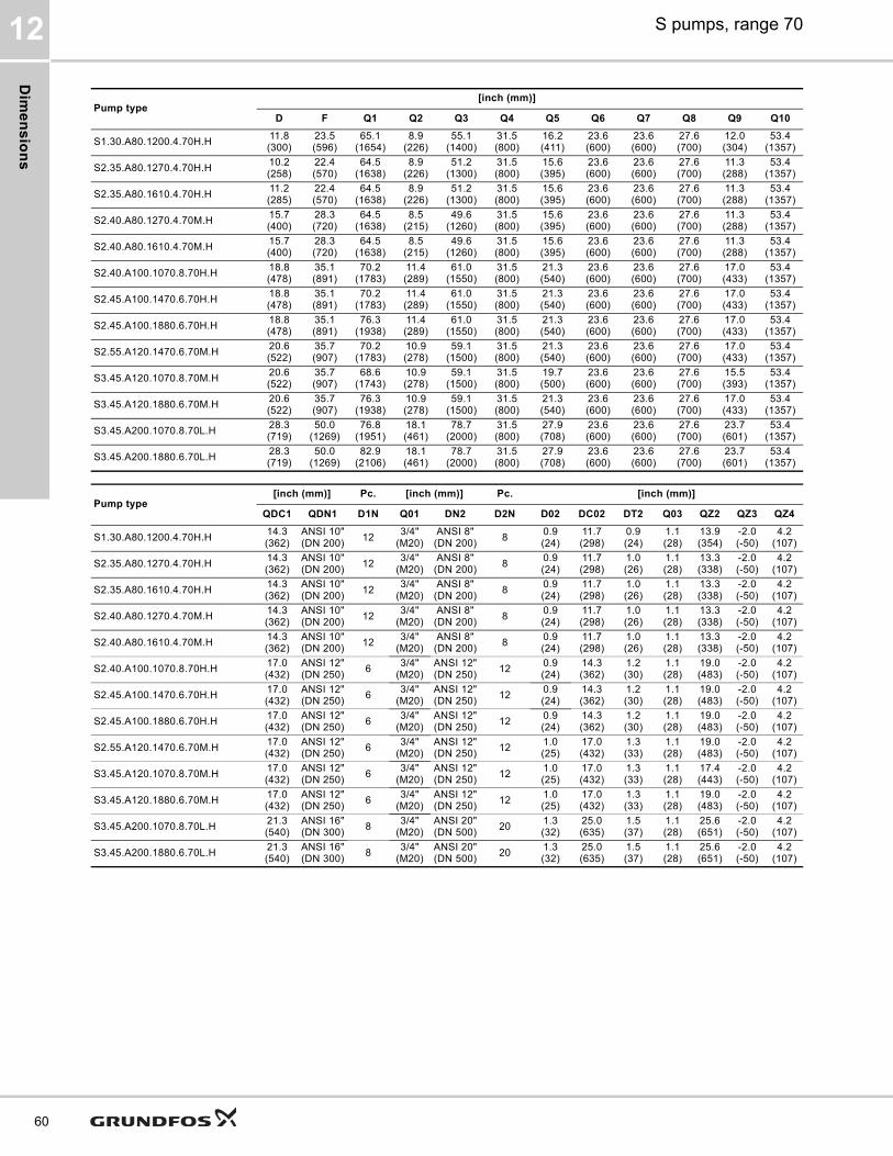
Dim
en
sio
ns
S pumps, range 7012
60
Pump type[inch (mm)]
D F Q1 Q2 Q3 Q4 Q5 Q6 Q7 Q8 Q9 Q10
S1.30.A80.1200.4.70H.H 11.8(300)
23.5(596)
65.1(1654)
8.9(226)
55.1(1400)
31.5(800)
16.2(411)
23.6(600)
23.6(600)
27.6(700)
12.0(304)
53.4(1357)
S2.35.A80.1270.4.70H.H 10.2(258)
22.4(570)
64.5(1638)
8.9(226)
51.2(1300)
31.5(800)
15.6(395)
23.6(600)
23.6(600)
27.6(700)
11.3(288)
53.4(1357)
S2.35.A80.1610.4.70H.H 11.2(285)
22.4(570)
64.5(1638)
8.9(226)
51.2(1300)
31.5(800)
15.6(395)
23.6(600)
23.6(600)
27.6(700)
11.3(288)
53.4(1357)
S2.40.A80.1270.4.70M.H 15.7(400)
28.3(720)
64.5(1638)
8.5(215)
49.6(1260)
31.5(800)
15.6(395)
23.6(600)
23.6(600)
27.6(700)
11.3(288)
53.4(1357)
S2.40.A80.1610.4.70M.H 15.7(400)
28.3(720)
64.5(1638)
8.5(215)
49.6(1260)
31.5(800)
15.6(395)
23.6(600)
23.6(600)
27.6(700)
11.3(288)
53.4(1357)
S2.40.A100.1070.8.70H.H 18.8(478)
35.1(891)
70.2(1783)
11.4(289)
61.0(1550)
31.5(800)
21.3(540)
23.6(600)
23.6(600)
27.6(700)
17.0(433)
53.4(1357)
S2.45.A100.1470.6.70H.H 18.8(478)
35.1(891)
70.2(1783)
11.4(289)
61.0(1550)
31.5(800)
21.3(540)
23.6(600)
23.6(600)
27.6(700)
17.0(433)
53.4(1357)
S2.45.A100.1880.6.70H.H 18.8(478)
35.1(891)
76.3(1938)
11.4(289)
61.0(1550)
31.5(800)
21.3(540)
23.6(600)
23.6(600)
27.6(700)
17.0(433)
53.4(1357)
S2.55.A120.1470.6.70M.H 20.6(522)
35.7(907)
70.2(1783)
10.9(278)
59.1(1500)
31.5(800)
21.3(540)
23.6(600)
23.6(600)
27.6(700)
17.0(433)
53.4(1357)
S3.45.A120.1070.8.70M.H 20.6(522)
35.7(907)
68.6(1743)
10.9(278)
59.1(1500)
31.5(800)
19.7(500)
23.6(600)
23.6(600)
27.6(700)
15.5(393)
53.4(1357)
S3.45.A120.1880.6.70M.H 20.6(522)
35.7(907)
76.3(1938)
10.9(278)
59.1(1500)
31.5(800)
21.3(540)
23.6(600)
23.6(600)
27.6(700)
17.0(433)
53.4(1357)
S3.45.A200.1070.8.70L.H 28.3(719)
50.0(1269)
76.8(1951)
18.1(461)
78.7(2000)
31.5(800)
27.9(708)
23.6(600)
23.6(600)
27.6(700)
23.7(601)
53.4(1357)
S3.45.A200.1880.6.70L.H 28.3(719)
50.0(1269)
82.9(2106)
18.1(461)
78.7(2000)
31.5(800)
27.9(708)
23.6(600)
23.6(600)
27.6(700)
23.7(601)
53.4(1357)
Pump type[inch (mm)] Pc. [inch (mm)] Pc. [inch (mm)]
QDC1 QDN1 D1N Q01 DN2 D2N D02 DC02 DT2 Q03 QZ2 QZ3 QZ4
S1.30.A80.1200.4.70H.H 14.3(362)
ANSI 10"(DN 200) 12 3/4"
(M20)ANSI 8"(DN 200) 8 0.9
(24)11.7(298)
0.9(24)
1.1(28)
13.9(354)
-2.0(-50)
4.2(107)
S2.35.A80.1270.4.70H.H 14.3(362)
ANSI 10"(DN 200) 12 3/4"
(M20)ANSI 8"(DN 200) 8 0.9
(24)11.7(298)
1.0(26)
1.1(28)
13.3(338)
-2.0(-50)
4.2(107)
S2.35.A80.1610.4.70H.H 14.3(362)
ANSI 10"(DN 200) 12 3/4"
(M20)ANSI 8"(DN 200) 8 0.9
(24)11.7(298)
1.0(26)
1.1(28)
13.3(338)
-2.0(-50)
4.2(107)
S2.40.A80.1270.4.70M.H 14.3(362)
ANSI 10"(DN 200) 12 3/4"
(M20)ANSI 8"(DN 200) 8 0.9
(24)11.7(298)
1.0(26)
1.1(28)
13.3(338)
-2.0(-50)
4.2(107)
S2.40.A80.1610.4.70M.H 14.3(362)
ANSI 10"(DN 200) 12 3/4"
(M20)ANSI 8"(DN 200) 8 0.9
(24)11.7(298)
1.0(26)
1.1(28)
13.3(338)
-2.0(-50)
4.2(107)
S2.40.A100.1070.8.70H.H 17.0(432)
ANSI 12"(DN 250) 6 3/4"
(M20)ANSI 12"(DN 250) 12 0.9
(24)14.3(362)
1.2(30)
1.1(28)
19.0(483)
-2.0(-50)
4.2(107)
S2.45.A100.1470.6.70H.H 17.0(432)
ANSI 12"(DN 250) 6 3/4"
(M20)ANSI 12"(DN 250) 12 0.9
(24)14.3(362)
1.2(30)
1.1(28)
19.0(483)
-2.0(-50)
4.2(107)
S2.45.A100.1880.6.70H.H 17.0(432)
ANSI 12"(DN 250) 6 3/4"
(M20)ANSI 12"(DN 250) 12 0.9
(24)14.3(362)
1.2(30)
1.1(28)
19.0(483)
-2.0(-50)
4.2(107)
S2.55.A120.1470.6.70M.H 17.0(432)
ANSI 12"(DN 250) 6 3/4"
(M20)ANSI 12"(DN 250) 12 1.0
(25)17.0(432)
1.3(33)
1.1(28)
19.0(483)
-2.0(-50)
4.2(107)
S3.45.A120.1070.8.70M.H 17.0(432)
ANSI 12"(DN 250) 6 3/4"
(M20)ANSI 12"(DN 250) 12 1.0
(25)17.0(432)
1.3(33)
1.1(28)
17.4(443)
-2.0(-50)
4.2(107)
S3.45.A120.1880.6.70M.H 17.0(432)
ANSI 12"(DN 250) 6 3/4"
(M20)ANSI 12"(DN 250) 12 1.0
(25)17.0(432)
1.3(33)
1.1(28)
19.0(483)
-2.0(-50)
4.2(107)
S3.45.A200.1070.8.70L.H 21.3(540)
ANSI 16"(DN 300) 8 3/4"
(M20)ANSI 20"(DN 500) 20 1.3
(32)25.0(635)
1.5(37)
1.1(28)
25.6(651)
-2.0(-50)
4.2(107)
S3.45.A200.1880.6.70L.H 21.3(540)
ANSI 16"(DN 300) 8 3/4"
(M20)ANSI 20"(DN 500) 20 1.3
(32)25.0(635)
1.5(37)
1.1(28)
25.6(651)
-2.0(-50)
4.2(107)

We
igh
ts
S pumps, range 70 13
13. Weights
Weights include 15 ft (15 m) cable.
Pump typeWeight
[lbs (kg]]
S1.30.A80.1200.4.70H.S 2317 (1051)S1.30.A80.1200.4.70H.C 2626 (1191)S1.30.A80.1200.4.70H.D 2575 (1168)S1.30.A80.1200.4.70H.H 2824 (1281)S2.35.A80.1270.4.70H.S 2315 (1050)S2.35.A80.1270.4.70H.C 2557 (1160)S2.35.A80.1270.4.70H.D 2557 (1160)S2.35.A80.1270.4.70H.H 2886 (1300)S2.35.A80.1610.4.70H.S 2425 (1100)S2.35.A80.1610.4.70H.C 2535 (1150)S2.35.A80.1610.4.70H.D 2756 (1250)S2.35.A80.1610.4.70H.H 3086 (1400)S2.40.A80.1270.4.70M.S 2315 (1050)S2.40.A80.1270.4.70M.C 2557 (1160)S2.40.A80.1270.4.70M.D 2557 (1160)S2.40.A80.1270.4.70M.H 2778 (1260)S2.40.A80.1610.4.70M.S 2315 (1050)S2.40.A80.1610.4.70M.C 2557 (1160)S2.40.A80.1610.4.70M.D 2557 (1160)S2.40.A80.1610.4.70M.H 2778 (1260)S2.45.A100.1470.6.70H.S 2535 (1150)S2.45.A100.1470.6.70H.C 2800 (1270)S2.45.A100.1470.6.70H.D 2800 (1270)S2.45.A100.1470.6.70H.H 3042 (1380)S2.45.A100.1880.6.70H.S 2800 (1270)S2.45.A100.1880.6.70H.C 3086 (1400)S2.45.A100.1880.6.70H.D 3086 (1400)S2.45.A100.1880.6.70H.H 3351 (1520)S2.40.A100.1070.8.70H.S 2535 (1150)S2.40.A100.1070.8.70H.C 2800 (1270)S2.40.A100.1070.8.70H.D 2800 (1270)S2.40.A100.1070.8.70H.H 3042 (1380)S2.55.A120.1470.6.70M.S 2866 (1300)S2.55.A120.1470.6.70M.C 3153 (1430)S2.55.A120.1470.6.70M.D 3153 (1430)S2.55.A120.1470.6.70M.H 3439 (1560)S3.45.A120.1070.8.70M.S 2866 (1300)S3.45.A120.1070.8.70M.C 3153 (1430)S3.45.A120.1070.8.70M.D 2976 (1350)S3.45.A120.1070.8.70M.H 3285 (1490)S3.45.A120.1880.6.70M.S 3131 (1420)S3.45.A120.1880.6.70M.C 3439 (1560)S3.45.A120.1880.6.70M.D 3439 (1560)S3.45.A120.1880.6.70M.H 3748 (1700)S3.45.A200.1070.8.70L.S 3858 (1750)S3.45.A200.1070.8.70L.C 3638 (1800)S3.45.A200.1070.8.70L.D 3638 (1800)S3.45.A200.1070.8.70L.H 4233 (1920)S3.45.A200.1880.6.70L.S 4299 (1950)S3.45.A200.1880.6.70L.C 4630 (2100)S3.45.A200.1880.6.70L.D 4409 (2000)S3.45.A200.1880.6.70L.H 4718 (2140)
61

Fla
ng
e fo
rce
s
S pumps, range 7014
62
14. Flange forces
Fig. 38 Pump characteristics
The flange forces and moments are according to EN ISO 5199.Forces can be found for both horizontal and vertical installations in table B.3 in EN ISO 5199, by selecting the correct flange dimension. Forces cannot be used directly for end-suction wastewater pumps without using a coefficient which can be found in table B.5 in EN ISO 5199 by selecting the correct pump family.For Grundfos wastewater pumps, the pump families and coefficients are as stated below.
TM06
490
1 31
15 -
TM06
490
3 31
15 -
TM06
490
2 31
15
Z
Y
YZ
X
Y
X
Z
Z
Y
X
Horizontal installations
Vertical installations
Base unit
Horizontally installed pumpsPump family A4 = Coefficient 0.35
Vertically installed pumpsPump family 10A = Coefficient 0.30

Gru
nd
fos
Pro
du
ct
Ce
nte
r
S pumps, range 70 15
15. Grundfos Product Center
Online search and sizing tool to help you make the right choice.http://product-selection.grundfos.com
All the information you need in one place
Performance curves, technical specifications, pictures, dimensional drawings, motor curves, wiring diagrams, spare parts, service kits, 3D drawings, documents, system parts. The Product Center displays any recent and saved items - including complete projects - right on the main page.
Downloads
On the product pages, you can download installation and operating instructions, data booklets, service instructions, etc. in PDF format.
TM07
238
4TM
07 2
383
1
2 3 4 5
Pos. Description
1 This drop-down menu enables you to set the search function to "Products" or "Literature".2 SIZING enables you to size a pump based on entered data and selection choices.3 CATALOGUE gives you access to the Grundfos product catalogue.
4
REPLACEMENT enables you to find a replacement product.Search results will include information on• the lowest purchase price• the lowest energy consumption• the lowest total life cycle cost.
5 LIQUIDS enables you to find pumps designed for aggressive, flammable or other special liquids.
63

Gru
nd
fos
Pro
du
ct C
en
ter
S pumps, range 7015
64
Grundfos GO
Mobile solution for professionals on the GO!
Grundfos GO is the mobile tool box for professional users on the go. It is the most comprehensive platform for mobile pump control and pump selection including sizing, replacement and documentation. It offers intuitive, handheld assistance and access to Grundfos online tools, and it saves valuable time for reporting and data collection.
GET IT ON

65

66

67
97682353 01.2021
ECM: 1301833
GRUNDFOS Chicago3905 Enterprise CourtP.O. Box 6620Aurora, IL 60598-0620Phone: +1-630-236-5500Fax: +1-630-236-5511
GRUNDFOS Kansas City9300 Loiret BoulevardLenexa, Kansas 66219Phone: +1-913-227-3400Fax: +1-913-227-3500www.grundfos.us
GRUNDFOS Canada2941 Brighton RoadOakville, Ontario L6H 6C9 CanadaPhone: +1-905 829 9533Fax: +1-905 829 9512www.grundfos.ca
GRUNDFOS México Boulevard TLC No. 15Parque Industrial Stiva AeropuertoC.P. 66600 Apodaca, N.L MexicoPhone: +011-52-81-8144 4000Fax: +011-52-81-8144 4010www.grundfos.mx Tr
adem
arks
dis
play
ed in
this
mat
eria
l, in
clud
ing
but n
ot li
mite
d to
Gru
ndfo
s, th
e G
rund
fos
logo
and
“be
thin
k in
nova
te” a
re re
gist
ered
trad
emar
ks o
wne
d by
The
Gru
ndfo
s G
roup
. All
right
s re
serv
ed.
© 2
021
Gru
ndfo
s H
oldi
ng A
/S, a
ll rig
hts
rese
rved
.