s-series - wabtec corporation€¦ · 32dsst03.c 1 - 1 i. s-series® public use introduction he...
TRANSCRIPT

10/10/11 32DSST03.C
U.S. Patent Nos: 5,228,538; 5,308,215; 5,373,915; 5,445,488; 5,605,431; 5,944,473 Australian Patent Nos: 661127; 687066 Canadian Patent No: 2,129,821
German Patent No: EP 0625896 B1 U.K. Patent No: EP 0625896 B1 Other U.S. and foreign patents pending.
©2011 RICON CORPORATIONAll Rights ReservedPrinted in the United States of America
OPERATOR MANUAL
S-Series® DOT - Public Use Lift
32DSST03.C i
This RICON product must be installed and serviced by a Ricon dealer or qualified service technician.
The operator must refer to this manual for operating instructions, then retain it for future reference.
“DOT – Public Use Lift” verifies that this plat-form lift meets the public use lift requirements of FMVSS no. 403. This lift may be installed on all vehicles appropriate for the size and weight of the lift, but must be installed on buses, school buses, and multi-purpose pas-senger vehicles other than motor homes with a gross vehicle weight rating (GVWR) that ex-ceeds 10,000 lbs (4,536 kgs).
Customer Information
Customer name Installing dealer
Date installed
Serial number

32DSST03.C ii
REVISION RECORD
REV PAGES DESCRIPTION OF CHANGE ECR/ECO
32DSST03. C
Cover Update to Illustration and Logo.
6560
i Update to cover information.
1-1 Update to illustration.
1-2 Update to warranty inforamation
1-4 Update to Figure 1-1.
2-1 Update to Figure 2-2 Caption.
2-1 Updated to Safety Precautions.
2-3 Update to Figure 2-4.
2-4 Update to Figure 2-5.
2-8 Update to instructions 1.c.
2-9 Update to instruction 2.c.
2-12 Update to instruction 1.e.
3-3 Update to Figure 3-1.

32DSST03.C iii
TABLE OF CONTENTS
Chapter: Page
I. INTRODUCTION .............................................................................................. 1-1
A. PRODUCT SUPPORT ................................................................................ 1-1 B. PRODUCT WARRANTY ............................................................................. 1-2 C. SHIPMENT INFORMATION ........................................................................ 1-3 D. GENERAL SAFETY PRECAUTIONS ............................................................ 1-3 E. MAJOR LIFT COMPONENTS ..................................................................... 1-4
II. OPERATING INSTRUCTIONS ........................................................................... 2-1
A. SAFETY PRECAUTIONS ............................................................................ 2-1 B. DAILY SAFETY CHECK .............................................................................. 2-2 C. PLATFORM MOTIONS ............................................................................... 2-3 D. CONTROLS AND INDICATORS .................................................................. 2-4
• CONTROL PENDANT ......................................................................... 2-4
• CIRCUIT BREAKERS AND INDICATOR LIGHTS ................................... 2-5
• BRIDGEPLATE LOAD SENSOR ........................................................... 2-6
• THRESHOLD SAFETY SYSTEM .......................................................... 2-6
• MANUAL BACK-UP PUMP ................................................................. 2-7
• LIFT CYCLE COUNTER ....................................................................... 2-7 E. NORMAL LIFT OPERATION ....................................................................... 2-8
1. ENTERING VEHICLE .......................................................................... 2-8 2. EXITING VEHICLE .............................................................................. 2-9 3. STOWING PLATFORM ....................................................................... 2-9
F. MANUAL OPERATION ............................................................................. 2-10 1. DEPLOY PLATFORM ........................................................................ 2-10 2. LOWER PLATFORM ......................................................................... 2-12 3. STOW PLATFORM ........................................................................... 2-12
G. MAINTENANCE AND REPAIR NOTE ......................................................... 2-12
III. MAINTENANCE ............................................................................................... 3-1
A. ADDITIONAL MAINTENANCE INFORMATION ............................................. 3-1 B. CLEANING ................................................................................................ 3-1 C. MAINTENANCE SCHEDULE ....................................................................... 3-1 D. DECAL PART NUMBERS AND LOCATIONS ................................................ 3-3

32DSST03.C iv
This page intentionally left blank.

32DSST03.C 1 - 1
I. S-SERIES® PUBLIC USE INTRODUCTION he RICON S-Series® Public Use wheelchair lift provides wheelchair access to vans and buses and is DOT compliant. The lift is operated by a trained attendant.
The lift is intended to provide wheelchair access to public vehicles including buses, school bus-es, and large multi-purpose passenger vehicles. The mechanical linkages provide smooth movement to the platform, which has a rated load capacity of 800 pounds (364 kilograms).
The lift contains a powerful electro-hydraulic pump with a built-in manual backup pump. If the lift loses electrical power, it can be raised or lowered manually.
By using the lift control switches, the lift is unfolded out from the vehicle (deployed). The user boards the large non-skid platform and the operator uses the control switches to gently lower the platform to the ground. After the user departs, the platform is raised and folded into the vehicle (stowed).
This manual contains warranty information, safety precautions, operating instructions, and maintenance information. It is important to user safety that the lift operator be completely familiar with the operating instructions. Once the lift is installed, it is very important that the lift be properly maintained by following the Ricon recommended maintenance and inspection instructions provided in Chapter III.
A. PRODUCT SUPPORT If there are questions about this manual, or additional copies are needed, please contact Ricon Product Support at one of the following locations:
Ricon Corporation 7900 Nelson Road Panorama City, CA 91402 ..................................................................... (818) 267-3000 Outside (818) Area Code ...................................................................... (800) 322-2884 World Wide Website ...................................................................... www.riconcorp.com
Vapor Ricon Europe Ltd. Littlemoss Business Park, Littlemoss Road Droylsden, Manchester United Kingdom, M43 7EF ........................................................... (+44) 161 301 6000
T
32DSST03.C 1 - 2
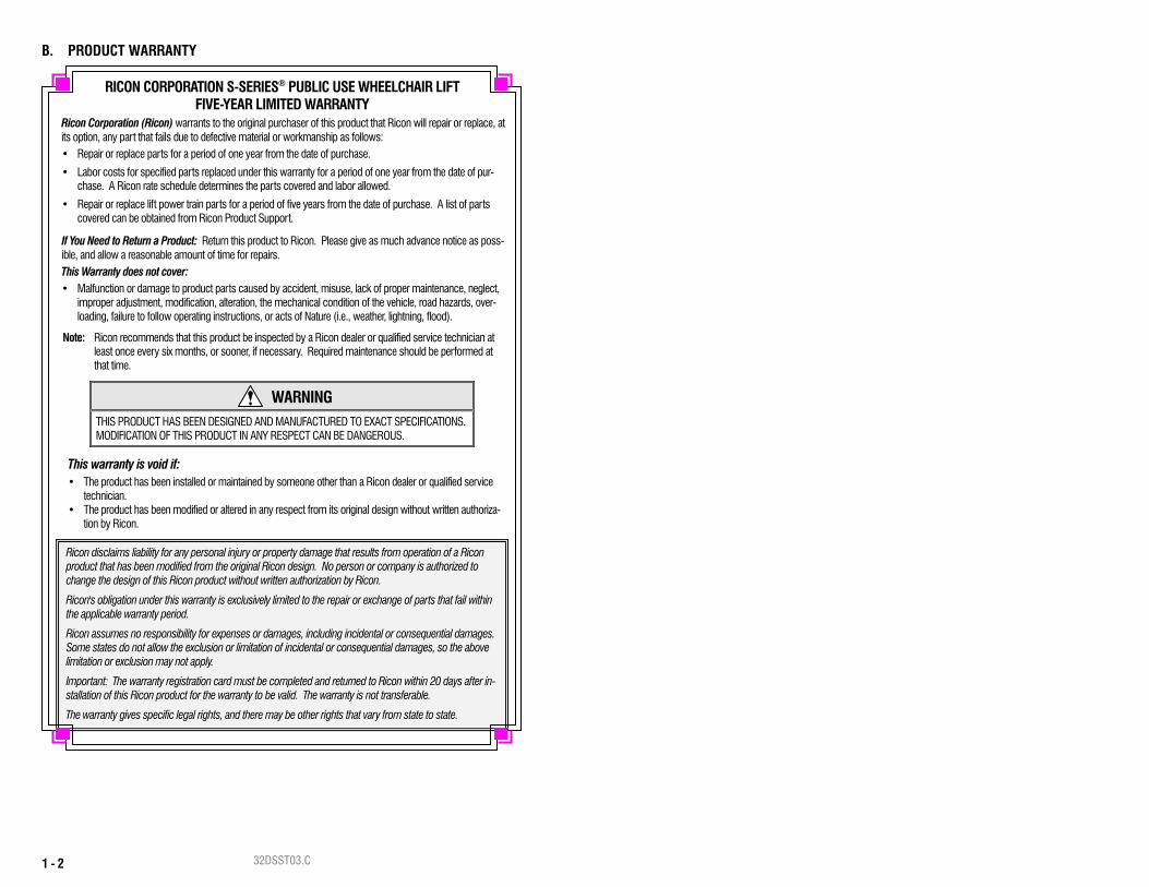
B. PRODUCT WARRANTY
RICON CORPORATION S-SERIES® PUBLIC USE WHEELCHAIR LIFT FIVE-YEAR LIMITED WARRANTY
Ricon Corporation (Ricon) warrants to the original purchaser of this product that Ricon will repair or replace, at its option, any part that fails due to defective material or workmanship as follows: • Repair or replace parts for a period of one year from the date of purchase.
• Labor costs for specified parts replaced under this warranty for a period of one year from the date of pur-chase. A Ricon rate schedule determines the parts covered and labor allowed.
• Repair or replace lift power train parts for a period of five years from the date of purchase. A list of parts covered can be obtained from Ricon Product Support.
If You Need to Return a Product: Return this product to Ricon. Please give as much advance notice as poss-ible, and allow a reasonable amount of time for repairs. This Warranty does not cover: • Malfunction or damage to product parts caused by accident, misuse, lack of proper maintenance, neglect,
improper adjustment, modification, alteration, the mechanical condition of the vehicle, road hazards, over-loading, failure to follow operating instructions, or acts of Nature (i.e., weather, lightning, flood).
Note: Ricon recommends that this product be inspected by a Ricon dealer or qualified service technician at least once every six months, or sooner, if necessary. Required maintenance should be performed at that time.
WARNING THIS PRODUCT HAS BEEN DESIGNED AND MANUFACTURED TO EXACT SPECIFICATIONS. MODIFICATION OF THIS PRODUCT IN ANY RESPECT CAN BE DANGEROUS.
This warranty is void if: • The product has been installed or maintained by someone other than a Ricon dealer or qualified service
technician. • The product has been modified or altered in any respect from its original design without written authoriza-
tion by Ricon.
Ricon disclaims liability for any personal injury or property damage that results from operation of a Ricon product that has been modified from the original Ricon design. No person or company is authorized to change the design of this Ricon product without written authorization by Ricon.
Ricon's obligation under this warranty is exclusively limited to the repair or exchange of parts that fail within the applicable warranty period.
Ricon assumes no responsibility for expenses or damages, including incidental or consequential damages. Some states do not allow the exclusion or limitation of incidental or consequential damages, so the above limitation or exclusion may not apply.
Important: The warranty registration card must be completed and returned to Ricon within 20 days after in-stallation of this Ricon product for the warranty to be valid. The warranty is not transferable.
The warranty gives specific legal rights, and there may be other rights that vary from state to state.

32DSST03.C 1 - 3
C. SHIPMENT INFORMATION When the product is received, unpack the product and check for freight damage. Claims
for any damage should be made to the carrier immediately. Be sure the installation kit contains all items listed on the kit packing list. Please report any
missing items immediately to Ricon Product Support. The warranty and owner registration cards must be completed and returned to Ricon within 20 days for the warranty to be valid.
The sales or service personnel must review the Warranty and Operator Manual with the user to be certain that they understand how to safely operate the product. Instruct the user to follow the operating instructions without exception.
D. GENERAL SAFETY PRECAUTIONS The following general safety precautions must be followed during operation: To avoid injury, always exercise caution when operating and be certain that hands, feet,
legs, and clothing are not in the path of product movement. Read and thoroughly understand the operating instructions before attempting to operate. Inspect the product before each use. If an unsafe condition, unusual noises or movements
exist, do not use it until the problem is corrected. Stand clear of doors and platform and keep others clear during operation. The product requires regular periodic maintenance. A thorough inspection is recommended
at least once every six months. The product should be maintained at the highest level of performance.

32DSST03.C 1 - 4
E. MAJOR LIFT COMPONENTS The references used throughout this manual are illustrated in Figure 1-1 and defined in Table 1-1. Refer to Chapter IV “Parts Diagrams and Lists” for more details.
FIGURE 1-1: S-SERIES PUBLIC USE WHEELCHAIR LIFT
RSM0027000
4 2
1
321
22
6
9
10
7
11
14
12
1516
19
17
18
23
20
24
85
13

32DSST03.C 1 - 5
TABLE 1-1: S-SERIES PUBLIC USE LIFT COMPONENT TERMS REF NAME DESCRIPTION 1, 2, 3, 4
Left, right, front, rear Position references when lift is viewed from outside of vehicle.
5 Bridgeplate load sensor
Senses if weight is present on the lowered bridgeplate.
6 Hydraulic cylinder (left and right) Telescoping single-acting cylinders convert
hydraulic pressure into platform lifting and folding force.
7 Hydraulic power unit
Contains hydraulic pump driven by electric motor that produces pressure to raise and fold platform, and a pressure release valve to unfold and lower it.
8 Audible alarm (inside housing for hydraulic unit) Announces when some-
thing has passed over threshold. Activated by threshold beam.
9 Cycle counter Visible at rear of housing, it records number of times platform has
moved from floor to ground and back to floor.
10 Visual alarm Flashing light makes it known when something has passed over
threshold. Activated by threshold beams.
11 Manual backup pump handle
Used to operate manual back up-pump (located on hydraulic pow-er unit cover).
12 Stow-Lock catch Engages latch located on bottom of bridgeplate when plat-
form is fully stowed.
13 Baseplate assembly
Bolts to vehicle floor; provides secure foundation for lift.
14 Threshold beams Light-beams detect presence of objects in threshold area.
15 Serial number Location of serial number decal.
16 Top and bottom arms
(left and right) Upper and lower links connecting vertical arm to base assembly.
17 Vertical arm (left and right) Connects platform to top and bottom arms.
18 Bridgeplate (inboard rollstop)
Plate bridges gap between platform and baseplate when platform is at floor level. Acts as barrier to prevent wheelchair from rolling off of the platform during "Up" and "Down" platform motions.
19 Handrail (left and right) Provides a handhold for standing passenger.
20 Occupant restraint belt
Electrically interlocked safety belt that is intended to prevent accele-ration of wheelchair from platform. Lift will not operate unless belt is properly connected.
21 Front rollstop Front barrier prevents the wheelchair from inadvertently rolling off of
the platform during lift operation.
22 Platform Component of lift where the wheelchair and occupant are situated
during "Up" and "Down" lift motions. 23 Platform light (left and right) Directs light onto platform surface.
24 Control pendant Hand-held device controls platform motions. END OF TABLE

32DSST03.C 1 - 6
This page intentionally left blank.

32DSST03.C 2 - 1
II. S-SERIES® PUBLIC USE OPERATING INSTRUCTIONS his chapter contains safety precautions, daily safety check instructions, control and indicator descriptions and operating instructions for the RICON S-Series® Public Use wheelchair lift.
This chapter must be thoroughly understood before using the lift.
A. SAFETY PRECAUTIONS The following safety precautions must be complied with when operating lift: Refer to Figure 2-1. Deploying the lift when vehicle is on sloped ground is hazardous. Op-
erate lift with vehicle parked on level ground.
Vehicle must be safely parked with parking brake set before using lift. Inspect lift before use. Do not use lift if an unsafe condition exists, or unusual noises or
movements are noticed, and contact a Ricon dealer for repair. Read and comply with all warning labels and symbols affixed to wheelchair lift. Refer to Figure 2-2. Due to variations in the size and configuration of mobility aids, for
maximum safety, Ricon recommends that passengers always face outward when riding the lift platform.
It is never safe for a wheelchair occupant to exit a vehicle facing inboard. It is not safe to rely on a threshold warning device (audible or other) to confirm that it is safe to exit vehicle while facing inboard. Exiting the vehicle while facing outboard allows for visual confirma-tion that the lift platform has been raised in the event that the threshold warning device is inoperative or unheard and prevents the occupant from exiting the vehicle backwards when the platform is still on the ground.
When exiting vehicle, verify that platform is at same height as floor and front rollstop is up and locked.
T
FIGURE 2-1: SLOPED PARKING HAZARD
FIGURE 2-2: RICON RECOMMENDS PASSENGERS FACE OUTBOARD WHEN RIDING LIFT PLATFORM

32DSST03.C 2 - 2
Do not place large equipment inside vehicle that can prevent pivoting of a wheelchair. Be-ing able to pivot assures that a passenger can safely exit facing outward.
The raised front rollstop prevents slow and unintentional rolling off of the platform. It is not intended to stop a fast-moving wheelchair, which might tip forward if the small front wheels collide with the rollstop.
Be certain wheelchair fits safely on platform; it must not extend beyond edges or interfere with rising and locking of front rollstop.
Do not operate with a load in excess of 800 lbs (364 kgs). Keep arms, legs, and clothing away from moving lift parts. The lift is intended for one wheelchair and its occupant or one standee. Do not overload lift. Refer to Figure 2-3. Do not stand in front of lift while deploying platform.
Keep others clear while operating lift. Do not allow an untrained person to operate lift. Careful supervision is necessary if used near children. Do not allow anyone to stand on bridgeplate. A bent bridgeplate can interfere with the plat-
form as it rises and lowers. Lock wheelchair brakes when on platform (power chair users must turn off power and set
brake). Use great care in wet conditions, because the wheelchair brakes are less effective if wheels
or platform are wet. Never leave platform outside of vehicle. Return platform to stowed position after use. Do not load an oversize wheelchair into vehicle if it is too large to pivot freely inside vehicle.
Read and understand these safety precautions. Review them periodically and ask other operators to read them as well. Contact a Ricon dealer or call Ricon Product Support if there are questions.
B. DAILY SAFETY CHECK Inspect the lift before each use and check that the following conditions are met before operating: All functions operate properly. DO NOT use if unusual noises or movements exist, and con-
tact a Ricon Dealer for repair. Vehicle interlock is operating properly. No objects that may interfere with operation are present. General appearance and lubrication are satisfactory and fasteners are tight.
FIGURE 2-3: STAND CLEAR OF PLATFORM
32DSST03.C 2 - 3
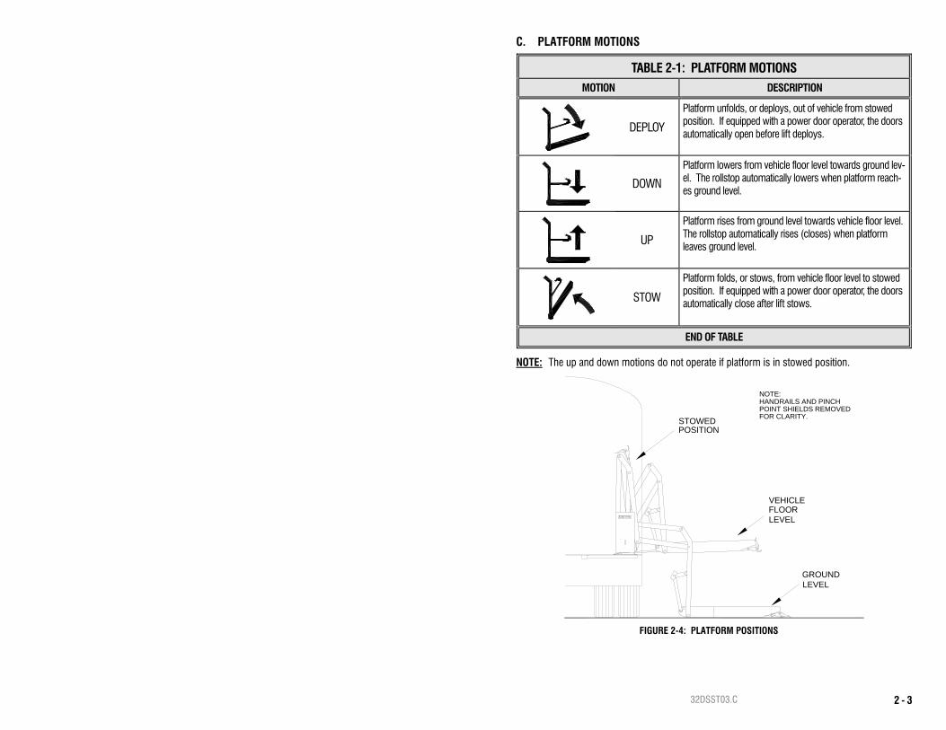
C. PLATFORM MOTIONS
TABLE 2-1: PLATFORM MOTIONS MOTION DESCRIPTION
DEPLOY
Platform unfolds, or deploys, out of vehicle from stowed position. If equipped with a power door operator, the doors automatically open before lift deploys.
DOWN
Platform lowers from vehicle floor level towards ground lev-el. The rollstop automatically lowers when platform reach-es ground level.
UP
Platform rises from ground level towards vehicle floor level. The rollstop automatically rises (closes) when platform leaves ground level.
STOW
Platform folds, or stows, from vehicle floor level to stowed position. If equipped with a power door operator, the doors automatically close after lift stows.
END OF TABLE
NOTE: The up and down motions do not operate if platform is in stowed position.
POSITIONSTOWED
GROUNDLEVEL
VEHICLE
LEVELFLOOR
FOR CLARITY.
HANDRAILS AND PINCHPOINT SHIELDS REMOVED
NOTE:
FIGURE 2-4: PLATFORM POSITIONS

32DSST03.C 2 - 4
D. CONTROLS AND INDICATORS
WARNING
THE LIFT IS ALLOWED TO OPERATE ONLY WHEN THE VEHICLE MANU-FACTURER INTERLOCK CIRCUITRY IS ACTIVATED. IF NECESSARY, REFER TO VEHICLE OPERATOR MANUAL FOR INTERLOCK INSTRUCTIONS. DO NOT ATTEMPT TO OPERATE LIFT WITH INTERLOCK BYPASSED.
CONTROL PENDANT Refer to Figure 2-5. The lift is operated with four buttons and a switch located on a hand-held, hard-wired remote-control pendant. Turn on the POWER switch and then press an appropriate button to control each lift motion. The POWER switch enables the pendant by providing power to it and must be turned on before the lift can be operated. When turned on, the power switch and each button illuminate. Pressing the DEPLOY button unfolds the platform from the vehicle, and pressing the STOW but-ton folds the platform back into the vehicle. Pressing the DOWN button lowers the platform to-wards the ground, and pressing the UP button raises the platform towards the floor. A button must be held depressed until the motion is completed. Movement of the platform can be halted at any time by releasing the button. The pendant is typically stowed on a wall-mounted clip inside the vehicle, near the lift.
S TO W
D EP LO Y
D O W N
U P
PO W ER EN AB LE
FIGURE 2-5: CONTROL PENDANT
32DSST03.C 2 - 5
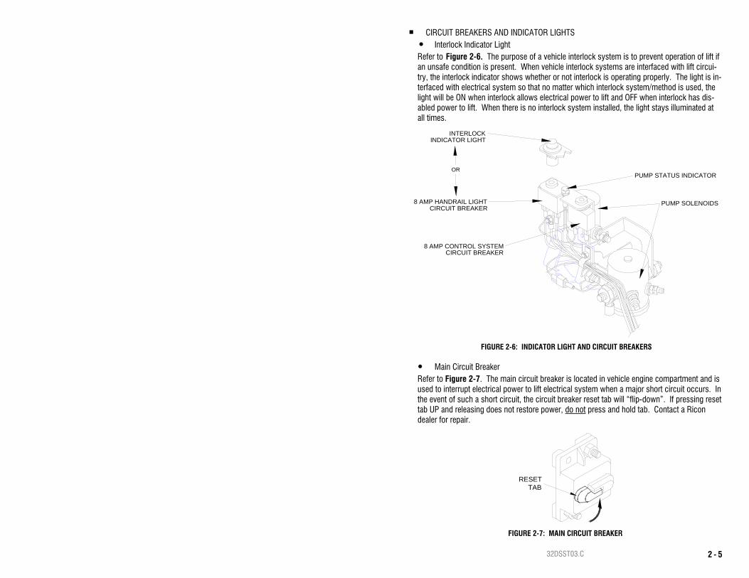
CIRCUIT BREAKERS AND INDICATOR LIGHTS Interlock Indicator Light
Refer to Figure 2-6. The purpose of a vehicle interlock system is to prevent operation of lift if an unsafe condition is present. When vehicle interlock systems are interfaced with lift circui-try, the interlock indicator shows whether or not interlock is operating properly. The light is in-terfaced with electrical system so that no matter which interlock system/method is used, the light will be ON when interlock allows electrical power to lift and OFF when interlock has dis-abled power to lift. When there is no interlock system installed, the light stays illuminated at all times.
Main Circuit Breaker Refer to Figure 2-7. The main circuit breaker is located in vehicle engine compartment and is used to interrupt electrical power to lift electrical system when a major short circuit occurs. In the event of such a short circuit, the circuit breaker reset tab will “flip-down”. If pressing reset tab UP and releasing does not restore power, do not press and hold tab. Contact a Ricon dealer for repair.
CIRCUIT BREAKER8 AMP CONTROL SYSTEM
8 AMP HANDRAIL LIGHT
INDICATOR LIGHTINTERLOCK
CIRCUIT BREAKERPUMP SOLENOIDS
PUMP STATUS INDICATOROR
FIGURE 2-6: INDICATOR LIGHT AND CIRCUIT BREAKERS
RESETTAB
FIGURE 2-7: MAIN CIRCUIT BREAKER
32DSST03.C 2 - 6
Door Operator Circuit Breaker (Optional) Refer to Figure 2-6. The circuit breaker for the power door operator is located on the hydrau-lic pump assembly. In the event of a door operator short circuit, the circuit breaker button will “pop-out”. If pressing and releasing button does not reset power, DO NOT press and hold. Contact a Ricon dealer for repair. Refer to appropriate Power Door Operator Service Manual for further details.
Control System Circuit Breaker Refer to Figure 2-6. The Control System Circuit Breaker is on hydraulic pump assembly. In case of a control system short circuit, the circuit breaker button will “pop-out”. If pressing and releasing button does not reset power, DO NOT press and hold. Contact a Ricon dealer for repair.
BRIDGEPLATE LOAD SENSOR
Refer to Figure 1-1 and Table 1-1 (in Chapter 1) for the location of the switch that detects the presence of a load on the bridgeplate. When the sensor switch detects that an object is present on the bridgeplate it inhibits lowering of the platform. This protects the passenger from possible injury when the bridgeplate rises. It also protects the bridgeplate from damage, which could later interfere with proper operation of the lift.
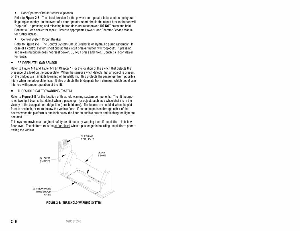
THRESHOLD SAFETY WARNING SYSTEM
Refer to Figure 2-8 for the location of threshold warning system components. The lift incorpo-rates two light beams that detect when a passenger (or object, such as a wheelchair) is in the vicinity of the baseplate or bridgeplate (threshold area). The beams are enabled when the plat-form is one inch, or more, below the vehicle floor. If someone passes through either of the beams when the platform is one inch below the floor an audible buzzer and flashing red light are actuated. This system provides a margin of safety for lift users by warning them if the platform is below floor level. The platform must be at floor level when a passenger is boarding the platform prior to exiting the vehicle.
APPROXIMATETHRESHOLD
AREA
FLASHINGRED LIGHT
BUZZER(INSIDE)
LIGHTBEAMS
FIGURE 2-8: THRESHOLD WARNING SYSTEM

32DSST03.C 2 - 7
MANUAL BACKUP PUMP Refer to Figure 2-9. The manual backup pump is used to operate lift if electrical power is not functional. The controls for the pump consist of a pump handle for raising the platform and a pump release valve for lowering it. Instructions for operating manual pump are provided in the MANUAL OPERATION paragraph, which is part of the LIFT OPERATION section in this chapter.
LIFT CYCLE COUNTER Refer to Figure 2-10. The cycle counter is located inside the hydraulic pump housing and visible through a slot on the rear side. The counter advances each time the platform moves through a complete cycle, which consists of the platform moving from the vehicle floor to the ground and back to the floor. The number of cycles displayed is used to schedule maintenance operations.
MANUAL BACKUPPUMP
PUMP HANDLESOCKET
PUMP PRESSURERELIEF VALVE
PUMP HANDLE
FIGURE 2-9: MANUAL BACK-UP PUMP & HANDLE
CYCLECOUNTER
FIGURE 2-10: CYCLE COUNTER

32DSST03.C 2 - 8
E. NORMAL LIFT OPERATION
WARNING
IMPROPER USE OF LIFT CAN RESULT IN PERSONAL INJURY. USERS MUST READ AND FOLLOW OPERATING INSTRUCTIONS. ADDITIONAL COPIES OF OPERATOR MANUAL ARE AVAILABLE FROM:
RICON CORPORATION 7900 NELSON ROAD
PANORAMA CITY, CA 91402 (800) 322-2884 OR (818) 267-3000
DO NOT EXCEED RATED LOAD CAPACITY OF 800 POUNDS (364 KGS). PRIOR TO USE, INSPECT WHEELCHAIR LIFT FOR PROPER FUNCTION, REQUIRED
MAINTENANCE, OR DAMAGE. IF A PROBLEM EXISTS, DO NOT USE LIFT AND CONTACT A RICON DEALER OR QUALIFIED SERVICE TECHNICIAN FOR REPAIR.
THIS LIFT IS FOR USE BY WHEELCHAIR OCCUPANTS AND STANDEES.
RICON CORPORATION DISCLAIMS LIABILITY FOR DAMAGE OR PERSONAL INJURY RESULTING FROM MODIFICATION TO LIFT, LACK OF MAINTENANCE OR REPAIR, NEGLIGENCE, ABUSE, OR FAIL-URE TO FOLLOW LIFT OPERATING INSTRUCTIONS.
Before operating lift, be certain vehicle is safely parked on a level area away from traffic. Provide space for lift operation and passenger boarding.
The lift operator must take special care to ensure that area is clear before deploying lift. Be certain there are no obstacles beneath platform.
Open doors completely if lift is not equipped with a power door operator. If so equipped, the vehicle doors will automatically open before platform deploys or close after platform is stowed.
If equipped with a safety interlock mechanism (e.g. transmission, parking brake, etc) be certain that it is properly engaged before attempting to operate lift. The lift will not operate until this feature has been engaged properly.
A person that uses the wheelchair lift while standing (does not require mobility aid equip-ment) is referred to in this manual as a Standee.
WARNING
ATTENDANT MUST REMAIN NEAR PASSENGER TO RENDER IMMEDIATE ASSISTANCE WHEN NECESSARY.
1. ENTERING VEHICLE
NOTE: The occupant restraint belt must be fastened to enable the DEPLOY, DOWN, and UP motions; the platform will not operate unless this safety mechanism is connected. Turn pendant power switch on.
a. DEPLOY PLATFORM - Push and hold DEPLOY button until platform completely un-folds from vehicle and stops at floor level.
b. LOWER PLATFORM - Push and hold DOWN button until lift contacts ground and rollstop opens completely.
c. Unfasten occupant restraint belt, carefully place wheelchair in center of platform, fac-ing outward (away from vehicle), and lock wheelchair brakes.
32DSST03.C 2 - 9
CAUTION Be certain wheelchair is safely within platform perimeter and does not interfere with operation of platform rollstop.
A Standee must stand near the center of the platform, facing in the direction of travel (into vehicle), and firmly grasp handrails.
d. Fasten occupant restraint belt. Insert belt tongue into buckle and listen for “click” then “tug” on belt tongue to confirm belt is securely fastened.
e. RAISE PLATFORM - Push and hold UP button until platform rises and stops automati-cally at vehicle floor level.
f. Release wheelchair brakes, carefully board passenger into vehicle, and secure wheel-chair.
g. Refer to “STOWING PLATFORM” section on next page and stow platform.
2. EXITING VEHICLE NOTE: The occupant restraint belt must be fastened to enable the DEPLOY and DOWN mo-
tions. The platform will not operate unless this safety mechanism is connected. a. DEPLOY PLATFORM - Push and hold DEPLOY button until platform completely un-
folds from vehicle and stops at vehicle floor level.
WARNING
VERIFY THAT PLATFORM IS AT VEHICLE FLOOR LEVEL AND FRONT ROLLSTOP IS UP AND LOCKED IN POSITION.
b. Fasten occupant restraint belt. Insert belt tongue into buckle and listen for “click” then “tug” on belt tongue to confirm belt is securely fastened.
c. Carefully place wheelchair in center of platform, facing outward (away from vehicle), and lock wheelchair brakes.
CAUTION
Do not stand on bridgeplate as platform lowers.
A Standee must stand near the center of the platform, facing in the direction of travel (away from vehicle), and firmly grasp handrails.
d. LOWER PLATFORM - Push and hold DOWN button until platform settles at ground level and front rollstop is fully lowered.
e. Unfasten occupant restraint belt, release wheelchair brakes, and carefully assist pas-senger off platform.
f. Refer to “STOWING PLATFORM” section and stow platform.
3. STOWING PLATFORM NOTE: The occupant restraint belt must be fastened to enable the UP and STOW motions.
The platform will not operate unless this safety mechanism is connected. a. If platform is at ground level, push and hold UP button until platform rises and stops
automatically at floor level. b. Push and hold STOW button until platform folds completely into vehicle.
32DSST03.C 2 - 10
CAUTION
Be certain lift has folded completely before closing doors. To prevent damage to doors, do not release switch until lift has folded completely and lift pump motor has stopped automatically.
c. Close vehicle doors if lift is not equipped with a power door operator. If so equipped, the vehicle doors will automatically close after platform is stowed.
F. MANUAL LIFT OPERATION The lift can be operated manually if lift electrical power is not functioning. Ricon recommends that manual operation be used only for exiting from vehicle. Preparation:
Be certain vehicle is on a level area and away from traffic. Allow space for platform move-ment plus space to exit from platform.
The vehicle operator must summon assistance to move vehicle to a safe area if a break down situation exists where vehicle cannot be moved under its own power.
Open doors manually if vehicle is not equipped with a power door operator. If equipped with a power door operator, refer to its operator manual for manual operation directions.
WARNING
FOLLOW PRECAUTIONS AT BEGINNING OF “LIFT OPERATION” SEC-TION WHEN USING MANUAL BACKUP SYSTEM TO EXIT VEHICLE.
NOTE: The threshold warning system is not active during manual operation and cannot be used to indicate platform height.
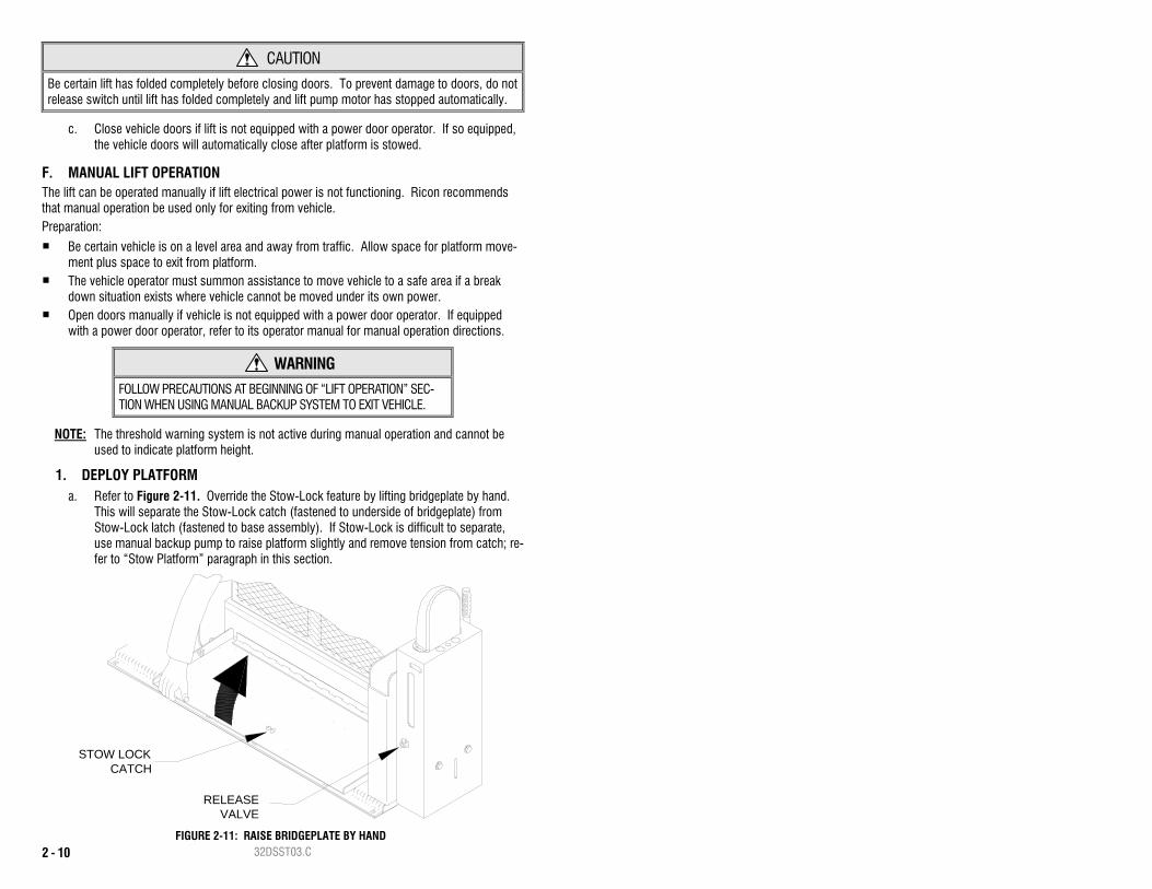
1. DEPLOY PLATFORM a. Refer to Figure 2-11. Override the Stow-Lock feature by lifting bridgeplate by hand.
This will separate the Stow-Lock catch (fastened to underside of bridgeplate) from Stow-Lock latch (fastened to base assembly). If Stow-Lock is difficult to separate, use manual backup pump to raise platform slightly and remove tension from catch; re-fer to “Stow Platform” paragraph in this section.
FIGURE 2-11: RAISE BRIDGEPLATE BY HAND
STOW LOCKCATCH
RELEASEVALVE
32DSST03.C 2 - 11
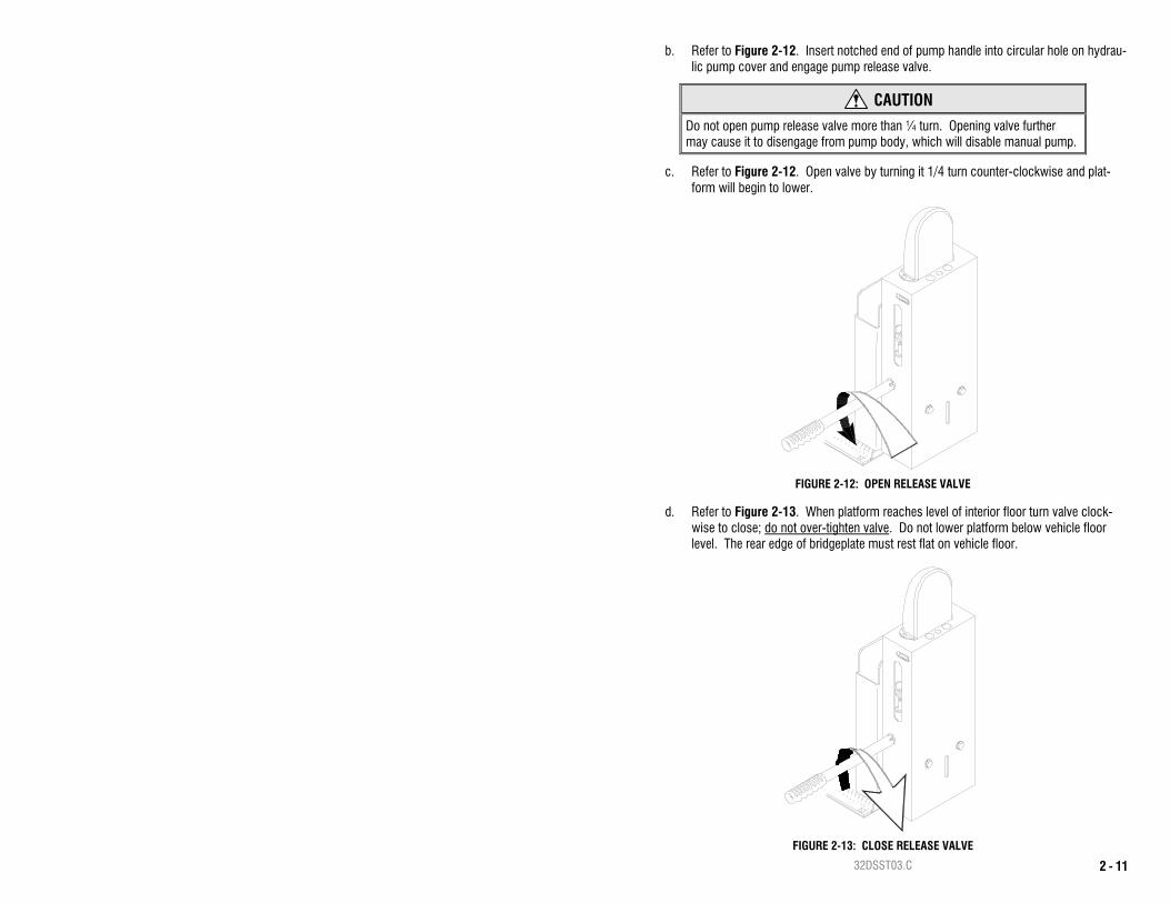
b. Refer to Figure 2-12. Insert notched end of pump handle into circular hole on hydrau-lic pump cover and engage pump release valve.
CAUTION
Do not open pump release valve more than ¼ turn. Opening valve further may cause it to disengage from pump body, which will disable manual pump.
c. Refer to Figure 2-12. Open valve by turning it 1/4 turn counter-clockwise and plat-form will begin to lower.
d. Refer to Figure 2-13. When platform reaches level of interior floor turn valve clock-wise to close; do not over-tighten valve. Do not lower platform below vehicle floor level. The rear edge of bridgeplate must rest flat on vehicle floor.
FIGURE 2-12: OPEN RELEASE VALVE
FIGURE 2-13: CLOSE RELEASE VALVE
32DSST03.C 2 - 12
e. Load passenger. Carefully place wheelchair in center of platform, facing outward (away from vehicle), and lock wheelchair brakes.
f. Fasten occupant restraint belt. Ensure restraint belt is securely fastened by clicking belt latch into buckle then tugging on belt to verify that belt buckle is locked.
2. LOWER PLATFORM
CAUTION
Do not open pump release valve more than ¼ turn. Opening valve further may cause it to disengage from pump body, which will disable manual pump.
a. Refer to Figure 2-12. Turn valve 1/4 turn counter-clockwise to begin lowering plat-form.
b. Hold valve open until platform settles at ground level. Refer to Figure 2-13. Turn handle clockwise to close valve; do not over-tighten valve.
c. Unfasten occupant restraint belt, release wheelchair brakes, and carefully assist pas-senger off platform.
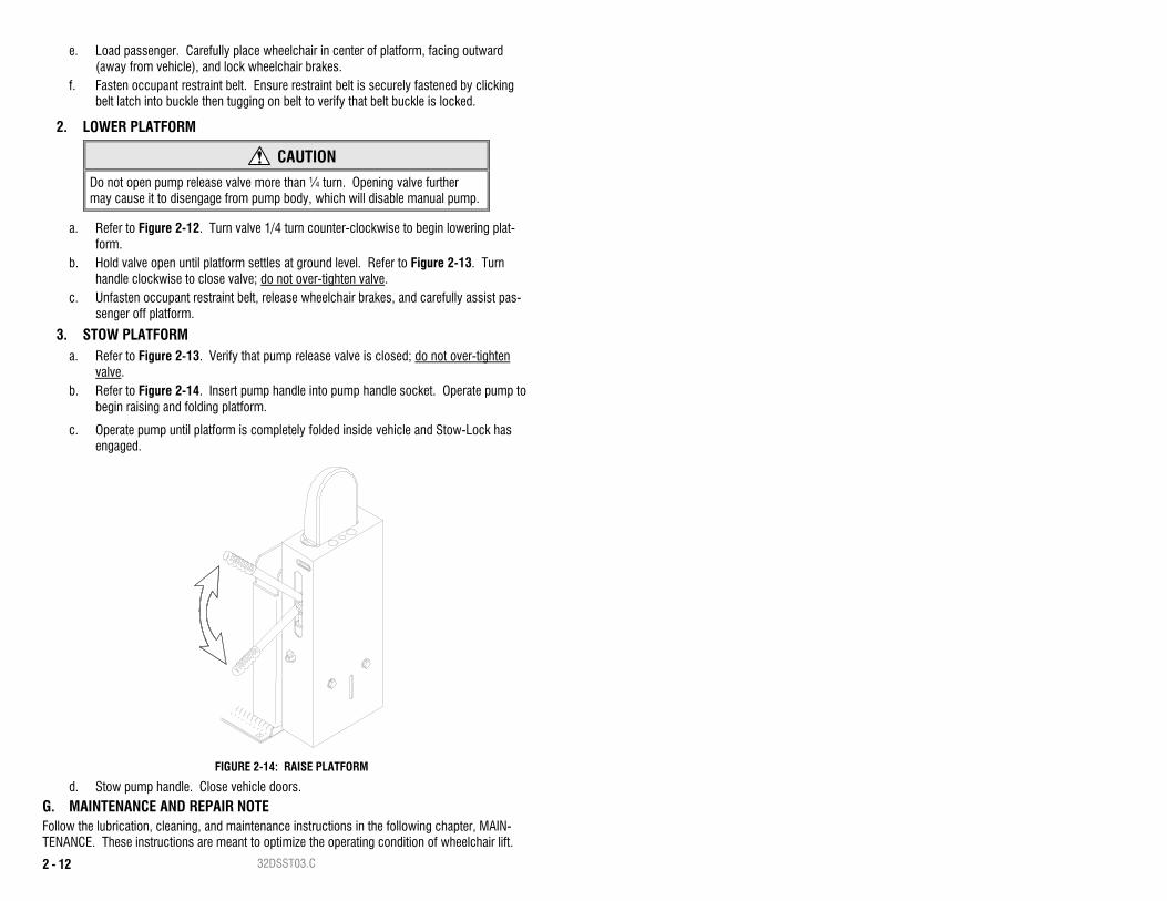
3. STOW PLATFORM a. Refer to Figure 2-13. Verify that pump release valve is closed; do not over-tighten
valve. b. Refer to Figure 2-14. Insert pump handle into pump handle socket. Operate pump to
begin raising and folding platform.
c. Operate pump until platform is completely folded inside vehicle and Stow-Lock has engaged.
d. Stow pump handle. Close vehicle doors.
G. MAINTENANCE AND REPAIR NOTE Follow the lubrication, cleaning, and maintenance instructions in the following chapter, MAIN-TENANCE. These instructions are meant to optimize the operating condition of wheelchair lift.
FIGURE 2-14: RAISE PLATFORM
32DSST03.C 3 - 1
III. S-SERIES® PUBLIC USE MAINTENANCE egular maintenance of the RICON S-Series® Public Use wheelchair lift will provide optimum performance and reduce the need for repairs. This chapter contains cleaning instructions, a
maintenance schedule, and decal information.
A. ADDITIONAL MAINTENANCE INFORMATION Additional maintenance information is available in the S-Series Public Use service manual, part number 32DSST04. This manual is available from Ricon in printed hard copy, or at the Ricon website in PDF format. The website is located at www.riconcorp.com. At the website, click on “Technical Documents”, “I agree”, and then “Service Manuals”.
WARNING
THIS RICON PRODUCT IS HIGHLY SPECIALIZED. MAINTENANCE AND REPAIRS MUST BE PERFORMED BY A RICON DEALER USING RICON REPLACEMENT PARTS. MODIFYING OR FAILING TO PROPERLY MAINTAIN THIS PRODUCT WILL VOID WARRANTY, AND MAY RESULT IN UNSAFE OPERATING CONDITIONS.
B. CLEANING Regular cleaning with mild soap (i.e. liquid hand soap or car wash liquid) and drying thoroughly will protect lift painted surfaces. Cleaning is especially important in areas where roads are salted in winter. Make sure that lift pivot points are clean and dry prior to lubrication.
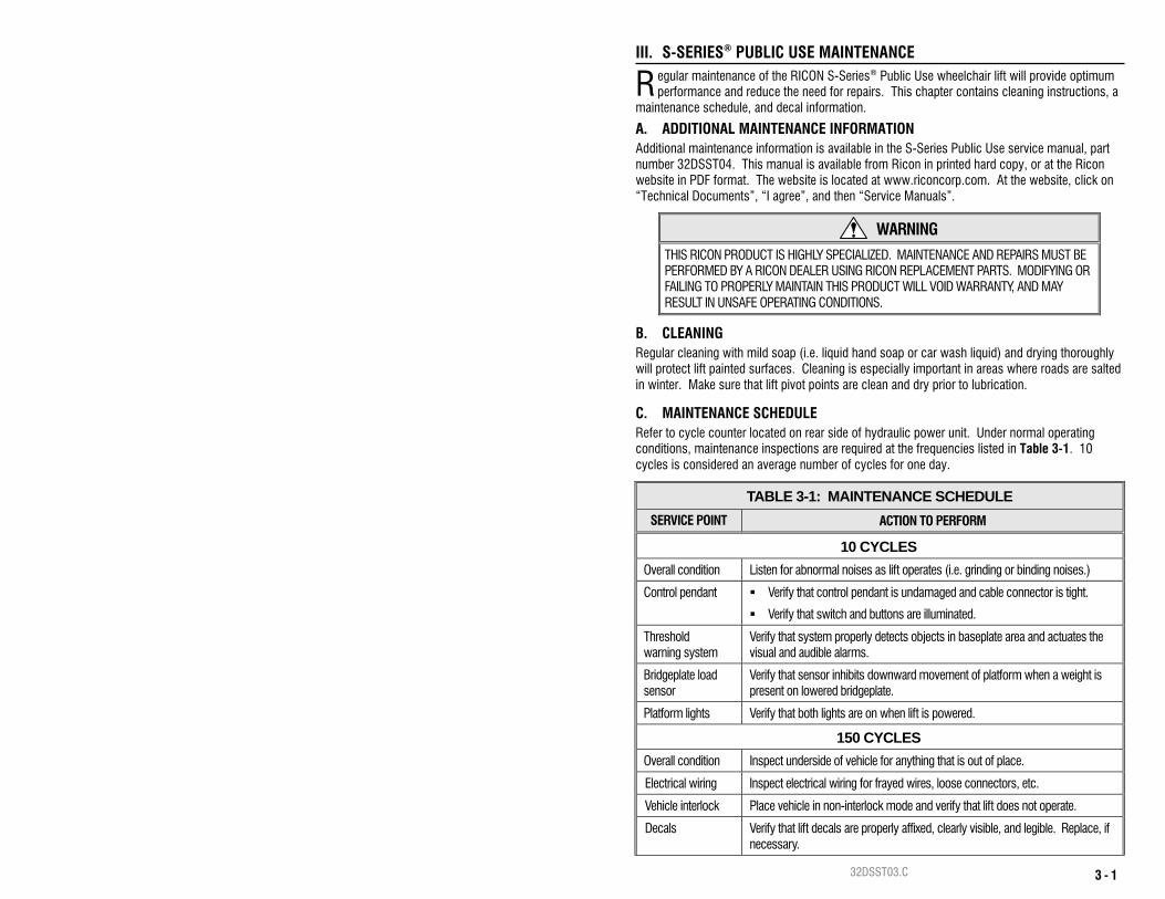
C. MAINTENANCE SCHEDULE Refer to cycle counter located on rear side of hydraulic power unit. Under normal operating conditions, maintenance inspections are required at the frequencies listed in Table 3-1. 10 cycles is considered an average number of cycles for one day.
TABLE 3-1: MAINTENANCE SCHEDULE SERVICE POINT ACTION TO PERFORM
10 CYCLES Overall condition Listen for abnormal noises as lift operates (i.e. grinding or binding noises.)
Control pendant Verify that control pendant is undamaged and cable connector is tight.
Verify that switch and buttons are illuminated.
Threshold warning system
Verify that system properly detects objects in baseplate area and actuates the visual and audible alarms.
Bridgeplate load sensor
Verify that sensor inhibits downward movement of platform when a weight is present on lowered bridgeplate.
Platform lights Verify that both lights are on when lift is powered.
150 CYCLES Overall condition Inspect underside of vehicle for anything that is out of place.
Electrical wiring Inspect electrical wiring for frayed wires, loose connectors, etc.
Vehicle interlock Place vehicle in non-interlock mode and verify that lift does not operate.
Decals Verify that lift decals are properly affixed, clearly visible, and legible. Replace, if necessary.
R
32DSST03.C 3 - 2
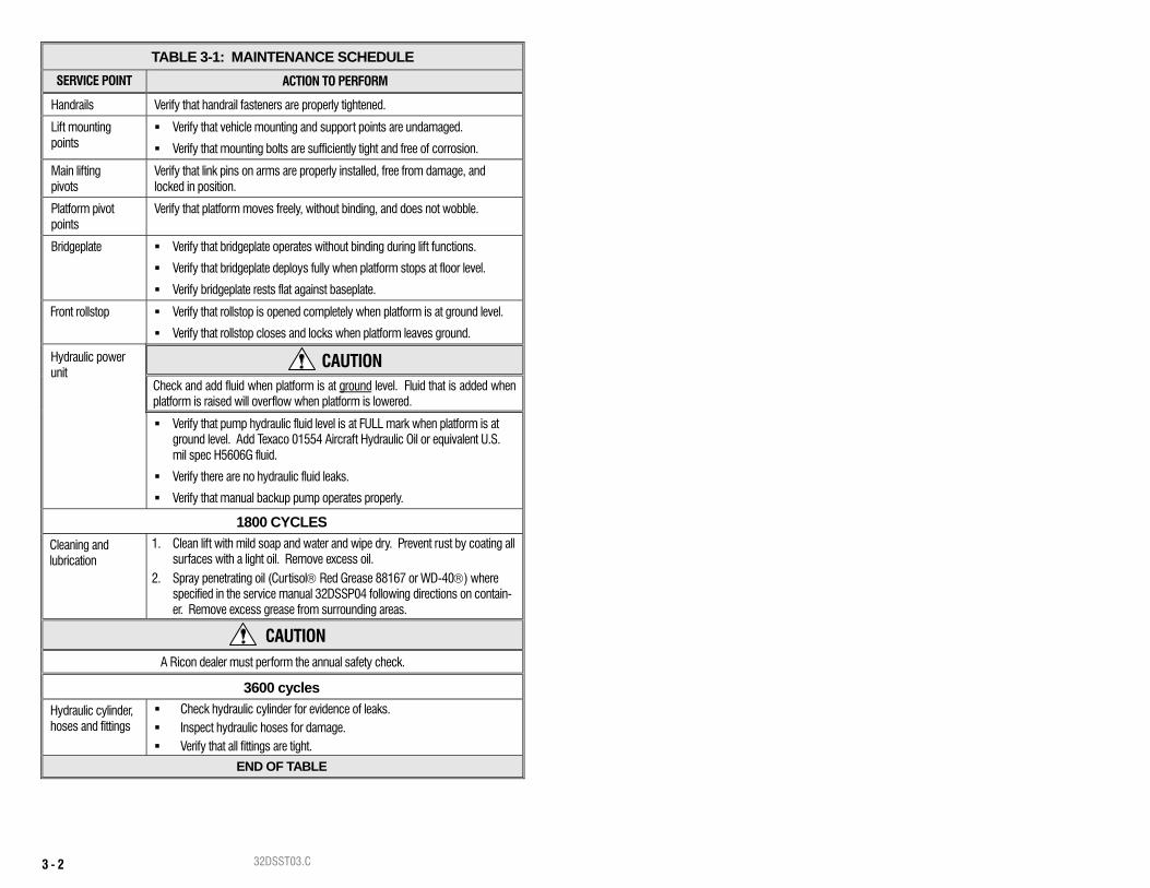
TABLE 3-1: MAINTENANCE SCHEDULE SERVICE POINT ACTION TO PERFORM
Handrails Verify that handrail fasteners are properly tightened.
Lift mounting points
Verify that vehicle mounting and support points are undamaged.
Verify that mounting bolts are sufficiently tight and free of corrosion.
Main lifting pivots
Verify that link pins on arms are properly installed, free from damage, and locked in position.
Platform pivot points
Verify that platform moves freely, without binding, and does not wobble.
Bridgeplate Verify that bridgeplate operates without binding during lift functions.
Verify that bridgeplate deploys fully when platform stops at floor level.
Verify bridgeplate rests flat against baseplate.
Front rollstop Verify that rollstop is opened completely when platform is at ground level.
Verify that rollstop closes and locks when platform leaves ground.
Hydraulic power unit
CAUTION Check and add fluid when platform is at ground level. Fluid that is added when platform is raised will overflow when platform is lowered.
Verify that pump hydraulic fluid level is at FULL mark when platform is at ground level. Add Texaco 01554 Aircraft Hydraulic Oil or equivalent U.S. mil spec H5606G fluid.
Verify there are no hydraulic fluid leaks.
Verify that manual backup pump operates properly.
1800 CYCLES Cleaning and lubrication
1. Clean lift with mild soap and water and wipe dry. Prevent rust by coating all surfaces with a light oil. Remove excess oil.
2. Spray penetrating oil (Curtisol® Red Grease 88167 or WD-40®) where specified in the service manual 32DSSP04 following directions on contain-er. Remove excess grease from surrounding areas.
CAUTION
A Ricon dealer must perform the annual safety check.
3600 cycles Hydraulic cylinder, hoses and fittings
Check hydraulic cylinder for evidence of leaks. Inspect hydraulic hoses for damage. Verify that all fittings are tight.
END OF TABLE

32DSST03.C 3 - 3
D. DECAL PART NUMBERS AND LOCATIONS Refer to Figure 3-1. Inspect decals at interval in Table 3-1. Inspect for chipping, peeling, fad-ing, and illegibility. Order replacement decals with part number given in Figure 3-1, and apply where shown.
RSM0027000
OPERATIONPN 262 14
M ANUAL
PN 321 36INSTRUCTIONSOPERATING
XX-XX-XXX
S -SE R IES LIFT
patentspending.
PUM P COVE R
PA TENT NO.
x,xx x,xxx;Austral ianPatent No.xxxxxx; CanadianPatent No.xxxxxxx;OtherU.S. and foreign
This product iscoveredbyoneor moreof thefollowingpatents:U.S.PatentsNos.x,xxx,xxx;x,xxx,xxx;x,xxx,xxx;x,xxx,xxx; x,xxx,xxx;
PN 32 -10 -17 3
S-SE RIES
PN 262 92
MadeinU.S.A.
C OR P OR A TIO N
mfg.date:
INNER SIDE OF HYDRAULIC
PA RT OF SE R IAL NU M BE R
REP LACEAB LE)CYLIN DER; ONLY RICON
DECAL (LOCATED ON NUM BER DECALPA RT OF SE RIAL
REP LACEAB LE)(ONLY RICON
7900NelsonR oad,PanoramaC ity,CA91402
STAND CLEAR
PN 261 85CAUTION
mfg. date:
12450 MontagueSt.,Pacoima, CA91331
M adeinU.S.A.
C OR P O R A TI ON
RESTRAINTBE LT
PN 261 55
STANDEE LOC ATIONPN 262 55
W HEELCHAIR & STANDEE LIFTSS-SERIES PUBLIC USE
Standees:
Stow Lift:
Enter Vehicle:
Exit Vehicle:
Deploy Lift:
I NSTALLER
7900 NELSON RD.RICONCORPORATION
WH EELCH AI R & STANDEE LIFT SS-SERIES/K-SERIES PUBLIC USE
(818) 267-3000(800) 322-2884
PANORAMA CITY, CA91402
OPERATINGINSTRUCTIONS
Stand ees:
MANUAL OPERATION
CAUTION
Stow Lift:
Exit Vehic le:
Enter Vehicle:
Deploy Lift:
WARNING
PUBLIC USE
PUBLIC USE
PN 321 46
INSTRUCTIONSOPERATING
EXTERIOR)(VE HICLE
D O T - P u b lic U s e L if t32113.A
PN 321 13USE LIFT
DOT - PUBLIC
PN 262 01LOAD
M AX IM UM
1 2
2621 4
M A N U A L O P E R A T IO N
1 2
R ICON LOG OPN 32 -10 -15 2
CLICK TUG
26155.C
FASTEN OCCU PANT RESTRAINTBE LT BEFORE OPER A TING LIF T .
FIGURE 3-1: S-SERIES PUBLIC USE DECAL LOCATIONS AND PART NUMBERS

32DSST03.C 3 - 4
This page intentionally left blank.