s t a n da r d c on t r a c t doc um en t s a n d t ec h n
TRANSCRIPT

STANDARD CONTRACT DOCUMENTS
AND
TECHNICAL SPECIFICATIONS
FOR
UTILITY AND STREET CONSTRUCTION
September 2019
CITY OF RAYMORE, MISSOURI
100 Municipal Circle Raymore, Missouri 64083
816-331-1852 (Telephone) 816-331-8067 (Fax)

STANDARD CONTRACT DOCUMENTS AND TECHNICAL SPECIFICATIONS
FOR UTILITY AND STREET CONSTRUCTION
CITY OF RAYMORE, MISSOURI
TABLE OF CONTENTS (2019)
SECTION Standard Technical Specifications
Table of Contents Contract Documents
Advertisement for Bids Contract Documents
Information for Bidders Contract Documents
Bid Proposal Form Contract Documents
Agreement Contract Documents
Performance Bond Contract Documents
Maintenance Bond Contract Documents
Payment Bond Contract Documents
Notice of Award Contract Documents
Notice to Proceed Contract Documents
General Conditions Contract Documents
Sanitary Sewer Specifications Sanitary Sewer
Standard Sanitary Details Sanitary Sewer
Storm Sewer Specifications Storm Sewer
Standard Storm Details Storm Sewer
Water Specifications Water
Standard Water Details Water
Street Specifications Street
Standard Street Details Street
Standard Technical Specifications
Water Main
Updated 9/2019
Page 2 of 19

Water Main Specifications
1.00 GENERAL DESIGN CRITERIA
1.01 General
The design criteria presented in this Article are the minimum standards to
be followed in the design and construction of the water distribution
systems within Raymore. These minimum standards are not intended to
be used as a substitute for actual construction specifications and design
computations.
1.02 Capacity
The water distribution system and any extension thereof shall have
adequate capacity to:
1. Supply the peak hour demands (estimated at 0.67 GPM/customer) of all
customers, domestic, public, commercial and industrial while maintaining
a pressure of not less than 35 pounds per square inch at all points of
delivery, without reducing the service to any customer below these
requirements.
2. For residential fire protection, the system must be capable of delivering
not less than 1,000 gallons per minute for two (2) hours for fire protection
on the day of maximum customer demand (estimated at 0.44
GPM/customer) with a residual pressure of not less than 20 pounds per
square inch to at least one point within 300 feet of each building to be
served or proposed to be served by such system and extension for
residential.
3. For other than residential fire protection, the system must be capable of
providing water in such quantity as to adequately protect life and
adjoining properties, as determined by the City of Raymore, consistent
with alternative protective measures.
1.03 Criteria for Estimating Demand
The latest version of the water model adopted by the City of Raymore
shall be used for evaluating the effect of new residential/commercial
development on the existing water distribution system.
The following criteria will be used in estimating the average day demand,
maximum day demand, and peak hour demand incident to the
determination of future water main sizes.
1. Residential population = N = number of dwelling units x 2.78
people/dwelling unit.
Standard Technical Specifications
Water Main
Updated 9/2019
Page 3 of 19

2. Average daily water demand of residential population in gallons per day
(gpd) R = N x 100 gallons/person.
3. Average daily commercial and industrial water demand in gpd = C =
number of commercial and industrial employees x 100 gallons/person.
NOTE: Appropriate additional water demand allowance shall be made for
commercial and/or industrial establishments of types having water
demands in excess of 100 gpd per employee.
4. Average daily school water demand in gpd = S = number of staff
employees and students x 20 gallons/person.
5. Average daily water demand (in gpd) = A = R + C + S.
6. Maximum daily water demand (in gpd) = M = A x 2.
7. Peak hours demand (in gpd) = P = M x 2.
8. Peak hour demand in gallons per minute (gpm) = P divided by 1440.
1.04 Main Designations
1. Transmission Mains - Transmission mains are classified as mains
transporting water from a water source to a pumping station or reservoir.
Transmission mains shall be 12 inches in diameter or larger. Materials
shall be ductile iron pipe conforming to the current AWWA specification
C151, Class 50 with polywrap. Transmission mains shall not be tapped
unless approved by the City Engineer.
2. Major Distribution Mains - Major distribution mains shall be all other
mains 12 inches in diameter or greater. Material shall be ductile iron
pipe conforming to the current AWWA specification C151, Class 50 with
polywrap. Fittings shall conform to the current AWWA specifications C110
and C153, and shall have a pressure rating of not less than that of the
pipe. Major distribution mains will only be tapped by minor distribution
mains. Connections to major distribution mains shall be made at intervals
not less than 1,000 feet.
3. Minor Distribution Mains - Minor distribution mains are classified as water
mains 6 inches to 12 inches in diameter. Material shall be ductile iron
pipe conforming to the current AWWA specification C151, Class 50.
Fittings shall conform to the current AWWA specifications C110 and C153
and shall have a pressure rating of not less than that of the pipe. Four
inch water mains are not permitted.
1.05 Grid System
Mains shall be laid on a loop or grid system with mains cross connected
not more than 1,000 feet apart. Cross mains to be installed as part of a
Standard Technical Specifications
Water Main
Updated 9/2019
Page 4 of 19

subdivision or platted lot shall be eight inches in diameter when required
by the City Engineer. The cost of the eight inch main shall be the
responsibility of the Contractor/Developer and is not eligible for city
upsizing reimbursement over the cost of a six inch diameter main.
1.06 Dead End Water Main
Dead end water mains shall not exceed 700 feet in length. All dead end
water mains including those to be extended in the future shall have fire
hydrant assemblies installed at the terminus point.
All dead end water mains, which are to be extended in the future, shall be
installed to the limits of the platted subdivision such that extensions to
the mains to serve adjacent subdivision plats may be connected at the
plat boundary and shall be installed with a valve and a temporary fire
hydrant. The valve shall be the same size as the main.
All dead end water lines which are not to be extended in the future shall
be a minimum diameter of six inches and shall extend to the lot line of
the last lot to be served.
1.07 Valves
Valves will be installed as follows; two valves at every tee, three valves at
every cross, an in-line valve every 1,100 feet or as directed by the City
Engineer.
1.08 Fire Hydrants
In water systems and extensions serving one-family and/or two family
residential subdivisions, fire hydrants shall be installed at such locations
that there will be at least one fire hydrant within 300 feet hose length to
the nearest wall of any building, existing or future. Maximum street
length between fire hydrants will not exceed 500 feet. Hydrants on
adjacent streets will not be considered in meeting the above
requirements.
In commercial, industrial and apartment house areas, fire hydrants shall
be provided so that in no case shall more than 300 feet of fire hose be
required to reach any point at the base of any exterior building wall from
the nearest fire hydrant to supply the stipulated fire flow.
Not more than one fire hydrant shall be located on any six inch dead end
main.
2.00 MATERIALS
2.01 Scope
This work shall consist of furnishing materials for, and installing water
lines and appurtenances in conformity with the lines and grades shown on
the approved plans or as directed by the City Engineer.
Standard Technical Specifications
Water Main
Updated 9/2019
Page 5 of 19

2.02 Water Mains and Fittings
1. Materials for Water Mains and Fittings shall be the following:
a. Ductile Iron Pipe - Ductile iron pipe shall conform to the current AWWA
specification C151, Class 50. Joints shall be mechanical or push on
type. Fittings shall conform to the current AWWA specifications C110
and C153 and shall have a pressure rating of not less than that of the
pipe. All transmission mains shall be polyethylene encased in
accordance with the current AWWA specification C105. Minimum
thickness shall be eight mils.
b. Prestressed Concrete Pressure Pipe, Steel Cylinder Type Prestressed
concrete pressure pipe, fittings and appurtenances shall conform to
the requirements of the current AWWA specification C301. Minimum
thickness of the steel cylinder shall be 16 gauge. Gaskets shall be
synthetic rubber.
2.03 Valves and Appurtenances
1. Butterfly Valve
a. Butterfly valves shall be used in all mains 24 inches or larger. Butterfly
valves shall be rubber seated, designed to provide a tight shut off and
conform to current AWWA specification C504. Valve disc shall seat 90
degrees with the pipe axis. Shaft seals shall be O-ring type. Direction
to open shall be counterclockwise and be marked as such.
b. Valve shafts and seat surfaces shall be constructed of 18-B Type 304
or Type 316 stainless steel.
c. Valves shall be Mueller, Clow, M & H, Kennedy, Pratt or approved
equal.
2. Gate Valves
a. Valves shall be resilient wedge types rated for 250 p.s.i. cold water
working pressure. Valve performance shall meet or exceed the
requirements of ANSI/AWWA C515. Valves shall meet the
requirements of Underwriters Laboratories Standard 262.
b. Valve wall thickness shall exceed AWWA C515 and AWWA C153.
c. Valve body, bonnet, seal plate, and wedge casting shall be constructed
of ductile iron in accordance with ASTM A536. The wedge casting shall
Standard Technical Specifications
Water Main
Updated 9/2019
Page 6 of 19

be 100% encapsulated with nitrile rubber. No epoxy coating is allowed
in wedge. This rubber shall be permanently bonded to the ductile iron
wedge casting and shall meet ASTM D429 tests for rubber to metal
bonding.
d. The stem and stem nut shall be made from high strength manganese
bronze, UNS alloy C86700. Thrust washers shall be located above and
below the thrust collar of the stem. The direction of opening for the
valve shall be Left (OL).
e. The body, bonnet, and seal plate shall be epoxy coated in accordance
with ANSI/NSF 61
f. All Fasteners shall be stainless steel.
g. Valves shall have laying lengths and clear waterway openings for
mechanical joint valves as listed below:
Valve Size Laying Length Waterway Diameter
2” 3 1/2” 2 3/16”
3” 4 3/4” 3 3/16”
4” 4 5/16” 4 3/16”
6” 4” 6 3/16”
8” 5 1/4” 8 3/16”
10” 6 7/8” 10 3/16”
12” 8” 12 3/16”
16” 14 1/2” 16 3/16”
20” 11” 20 3/16”
24” 16” 24 3/16”
3. Valves shall be EJ, Mueller, Clow, Waterous, American Flow Control,
(AFC), M & H, Kennedy, Pratt or approved equal.
4. Valve Coating.
a. All ferrous metal surfaces of valves and accessories, both interior and
exterior, shall be shop-painted with two coats epoxy conforming to
current AWWA specification C550.
5. Valve Boxes
Standard Technical Specifications
Water Main
Updated 9/2019
Page 7 of 19

a. All buried valves shall be provided with ferrous metal riser and cover.
Covers shall have the word "water" cast on it and painted blue.
6. Painted Parts
a. All parts shall be painted with an asphalt varnish in accordance with
current AWWA specification C500.
2.04 Fire Hydrants
1. All hydrants shall be the traffic model, break-away and conform to the
latest revisions of AWWA Standard C502. Fire hydrants shall be rated for
250 psi working pressure and be listed by Underwriters Laboratories Inc.
(UL 246) and meet the test requirements of Factory Mutual (FM 1510) at
this pressure.
2. Hydrants shall be of a true compression type, opening against the
pressure and closing with the pressure. Composition of the main valve
shall be a molded rubber having a durometer hardness of 91 +/- 5. The
rubber seat valve shall fit a 5 ¼" opening and not be less than 1" thick.
3. Fire hydrants shall be Three-way in design, having (1) 4-1/2” NST Pumper
nozzle, and (2) 2 1/2" Nat Std 2 7/8" Base, C Dome hose nozzle. Nozzles
shall “thread” counterclockwise into hydrant barrel utilizing "o" ring
pressure seals. A suitable nozzle lock shall be in place to prevent
inadvertent nozzle removal. Wedging devices and/or ductile iron retainer
rings to secure nozzles shall not be allowed.
4. The lubrication system shall be sealed from the waterway and any
external contaminants by use of "o" ring pressure seals. Anti-friction
washers shall be in place above and below the thrust collar of the
operating nut to further minimize operating torque. The grease reservoir
shall be factory filled with an FDA approved food grade lubricant. Oil shall
not be used.
5. The operating nut shall be a one piece design, manufactured of ASTM
B-584 bronze. It shall be 1 1/2" Pentagon- point to flat in size/shape. The
operating nut shall be affixed to the bonnet by means of an ASTM B-584
bronze hold down nut. The hold down nut shall be threaded into the
bonnet in such a manner as to prevent accidental disengagement during
the opening cycle of the hydrant. A resilient weather seal shall be
incorporated with the hold down nut, for the purpose of protecting the
operating mechanism from the elements.
Standard Technical Specifications
Water Main
Updated 9/2019
Page 8 of 19

6. The direction of opening shall be Left. An arrow shall be cast on the top of
the hydrant to indicate the opening direction.
7. The hydrant bonnet shall be attached to the upper barrel by no more than
six bolts and nuts. All nuts and bolts below grade shall be 304 stainless
steel.
8. The hydrant will have 5’0” Depth of bury, unless otherwise noted.
9. Hydrants shall be of the "Traffic Model" design, provided with a safety
coupling and flange design that will permit a full 360 degree facing of the
nozzles. The safety coupling shall be a one piece design. Multiple part or
cast iron coupling designs are not allowed.
10. The operating stem shall be a two piece design, not less than 1 ¼ "
diameter (excluding threaded or machined areas). Threads shall be Acme
type with no 60 deg. V threads allowed. Travel stops shall be in the
inlet/shoe and are not allowed in the bonnet area. Screws, pins, bolts or
fasteners used in conjunction with the stem coupling shall be stainless
steel.
11. The inside diameter of the hydrant barrels shall not be less than 7 inches
and the hydrant shall be painted Yellow.
12. Heavy duty drip shutoff (top plate) and valve seat shall be high strength
manganese bronze. Valve seat shall be installed in a bronze seat ring.
Drains shall be bronze lined and 3/8 inch diameter minimum. They shall
operate without the use of springs, toggles, tubes, levers or other
intricate synchronizing mechanisms. Lower valve plate shall be a one
piece ductile iron casting and not require a separate cap nut. Drains shall
be open and flushed during the first 4 turns of opening the hydrant before
positively closing while operating the hydrant.
13. The shoe connection shall be Mechanical Joint or as specified. The
inlet/shoe shall be fusion bonded epoxy coated per ANSI/AWWA C550 and
with an NSF61 approved coating having ample blocking pads for sturdy
setting. Six stainless steel bolts and nuts are required to fasten the shoe
to the lower barrel. The shoe/inlet shall be directly connected to the
standpipe flange. Designs using a sandwich piece in between the
standpipe and shoe/inlet shall not be allowed.
Standard Technical Specifications
Water Main
Updated 9/2019
Page 9 of 19
14. External parts- the top bonnet, upper standpipe, lower standpipe and
shoe shall be ductile iron to ensure strength throughout the exterior of
the hydrant- Gray Iron hydrant body parts will not be allowed.
15. Hydrants shall be manufactured optic yellow. Field painting is not
allowed.
16. Hydrants shall be furnished with a black plastic caps or shall be covered
with a black plastic bag until the hydrant is available for service.
Upon request, supplier shall furnish flow data indicating friction loss in psi
at a flow of 1,000 gpm from the pumper nozzle. Such friction loss shall
not exceed 2.5 psi. All cast components shall be made in the USA and
Comply with EPA (AIS) requirements of Section 436.
Approved hydrants are the EJ WaterMaster 5CD250 or approved equal.
2.05 Tapping Sleeves and Valves
Tapping sleeves and valves, when connecting to existing live mains or
where required by the approved Engineering drawings, shall be 200 psi,
resilient-seated, cast iron body, non-rising stem gate valves conforming
with all applicable requirements of the current AWWA specification C509.
Direction to open shall be counterclockwise and be marked as such.
Tapping sleeves shall be stainless steel and compatible with the tapping
valve.
Tapping sleeves and valves shall be Mueller, Clow, Waterous, American
Flow Control (AFC), M & H, Kennedy or approved equal.
3.00 INSTALLATION
3.01 Pipe, Hydrants, Valves, and Tapping Sleeves
1. Ductile Iron Pipe - Ductile iron pipe shall be installed in accordance with
the current AWWA specification C600. All joints, fittings and other
appurtenances, shall be laid at least 18 inches from any obstruction, fire
hydrants shall be 36 inches from any obstruction. Fire hydrants shall be
installed where shown on the Engineering Drawings and in accordance
with Standard Detail Wtr-1.
2. Prestressed Concrete Pipe - Prestressed concrete pipe shall be installed in
accordance with the current AWWA specification M9.
3.02 Traffic Control
Standard Technical Specifications
Water Main
Updated 9/2019
Page 10 of 19

Traffic Control devices shall be provided by the Contractor/Developer in
accordance with the current MUTCD to regulate, warn and guide traffic at
the work site.
3.03 Pipe Alignment and Grades
All pipe shall be laid and maintained to the required lines and grades, with
hydrants, valves and fittings at the required locations and with joints
centered and drawn "home", and with all valve and hydrant stems plumb.
The developer/contractor shall furnish line and grade stakes necessary for
the work. It shall be the Contractor's responsibility to preserve these
stakes from loss or displacement. The Engineer may order and replace
any stakes he deems necessary for the proper prosecution of the work.
Any replacements shall be at the Contractor's expense. All pipes shall be
laid to the depth shown on the contract drawings and/or cut sheets as
supplied by the Engineer. The Contractor shall satisfactorily maintain the
specified cover by a means approved by the Engineer. If additional bends
are required where not shown on the drawings to maintain alignment
around curves, the Contractor shall provide the required number and be
compensated at the unit price as proposed on the bid form. The following
is the maximum allowable joint deflection for the ductile iron pipe:
AWWA C-600 TABLE 1 and 2 SUMMARY
(20’ pipe length – except as noted.)
Pipe Size Mechanical Joint Push on Joint
6” 27”* 21”
8” 20”* 21”
12” 22” 21”
16” 15” 12”
18” 12” 12”
20” 12” 12”
24” 10” 12”
30” 10” 8”
36” 9” 8”
42” 8” 8”
48” 8” 8”
Note: * 18' Length
3.04 Thrust Restraints
All plugs, caps, tees, bends and hydrants shall be provided with thrust
blocks in accordance with Standard Detail Wtr-2 and Wtr-3. Concrete
thrust blocks shall have a minimum 28-day compressive strength of 4000
psi. Concrete shall be placed and cured for 24 hours prior to energizing
the water line.
Standard Technical Specifications
Water Main
Updated 9/2019
Page 11 of 19

Concrete shall extend from fitting to undisturbed soil and shall be
installed so that all joints are accessible. If adequate soil support cannot
be obtained, a mechanical restraining assembly shall be installed as
approved by the City Engineer.
3.05 Handling and Storage
All pipe, fittings, valves, hydrants and accessories shall be loaded,
unloaded, stored and installed in such a manner to prevent structural
damage or coating damage. Any damaged materials shall be replaced or
restored to its original condition at the Contractor/Developer’s expense.
3.06 Cleaning
All pipe, fittings, valves, hydrants and accessories shall be kept clean of
foreign matter while being handled or stored. During installation, foreign
matter shall not enter the pipe or appurtenances. At the end of each
working day, a temporary plug shall be installed at the termination of the
water line.
3.07 Inspection
A Public Works Inspector will inspect all pipe, fittings, valves, hydrants
and accessories for damage or defect prior to installation. Damaged or
defective materials shall be replaced or restored to its original condition
by the Contractor/Developer.
3.08 Connection to Existing Main
The Contractor/Developer shall furnish and install all of the fittings
necessary for connections between new water mains and existing water
mains. Tapping sleeves and valves are required when connecting to
existing live mains or where required by approved engineering drawings.
The installation of tapping sleeves and valves shall be done while a Public
Works Inspector is present.
Tapping into existing mains shall be done with no interruption of existing
services unless otherwise approved by the City Engineer 48 hours prior to
disruption of service. Valves on the existing water system or valves that
separate newly constructed mains from the existing water system shall be
operated by the Public Works Inspector.
Special care should be taken when making a connection to an existing
main. No foreign material or contaminants will be permitted to enter the
water system.
Thrust blocks shall be provided at the new connection to provide thrust
restraint in accordance with Standard Detail Wtr-2 and Wtr-3.
3.09 Service Connections
The City will install a corporation connection at the main for individual,
commercial, industrial and residential service lines up to one (1) inch in
Standard Technical Specifications
Water Main
Updated 9/2019
Page 12 of 19

diameter. The Contractor/Developer shall notify the Building Inspections
Department 48 hours in advance of requiring a service connection. Any
tap greater than one (1) inch is the Contractor’s responsibility.
Excavation for service connections shall be provided by the
Contractor/Developer. Installation of meters greater than two inch
diameter will be specifically approved by the City Engineer. Excavation
shall be backfilled within 24 hours.
3.10 Water Lines In Relation To Sewers – Separation of Water Mains, Sanitary
Sewers and Storm Sewers
1. Adequate Separation Factors - The following factors should be considered
in providing adequate separation:
a. materials and type of joints for water and sewer pipes,
b. soil conditions,
c. service and branch connections into the water main and sewer line,
d. compensating variations in the horizontal and vertical connections,
e. space for repair and alterations of water and sewer pipes,
f. off-setting of pipes around manholes and other sewer structures.
2. Parallel Installation
Water mains shall be laid at least ten feet horizontally from any existing
or proposed sanitary sewer and storm sewer. The distance shall be
measured edge to edge. In cases where it is not practical to maintain this
separation, the City Engineer may allow deviation on a case-by-case
basis, if supported by data from the design engineer. Such deviation may
allow installation of the water main closer to a sewer, provided that the
water main is laid in a separate trench or on an undisturbed earth shelf
located on one side of the sewer, and in either case, at such an elevation
that the bottom of the water main is at least 18 inches above the top of
the sewer.
3. Crossings
Water mains crossing sewers shall be laid to provide a minimum vertical
clear distance of 18 inches between the outside of the water main and the
outside of the sewer. This shall be the case where the water main is
either above or below the sewer. At crossings, a full length of water pipe
shall be located such that both joints will be as far from the sewer as
possible. Special structural support (i.e. encasement) for the water and
sewer pipes may be required.
Standard Technical Specifications
Water Main
Updated 9/2019
Page 13 of 19

4. Force Mains
There shall be at least a ten-foot horizontal separation between water
mains and sanitary sewer force mains. There shall be an 18-inch vertical
separation at crossings as required in Item 3.
5. Sewer Manholes and Other Structures
No water line shall be located closer than ten feet to any part of a sanitary
sewer manhole or storm sewer curb inlet, junction box, or other storm
sewer structure.
6. Exceptions
The City Engineer may approve on a specific case by case basis deviations
from the above requirements when the City Engineer has determined it is
impossible to obtain the specified separation distance.
3.11 Straddle Blocks
Straddle blocks shall be provided every 50 feet for water mains which
exceed ten percent slope and for the end of dead end water mains as
shown on Standard Detail Wtr-4. Concrete shall be placed and cured for
24 hours prior to energizing the water line.
3.12 Polyethylene Encasement
Polyethylene encasement shall be installed in accordance with the current
AWWA specification C105 and Standard Detail Wtr-5.
3.13 Stream Crossings Water mains at stream crossings shall be encased as
per Standard Detail San-6.
4.00 DISINFECTION
Precautions, methods, procedures and materials for disinfection shall
conform to current AWWA specification C651.
Precaution shall be taken to protect the interior of pipes, fittings and
valves against contamination. Pipe shall be handled in such a manner to
prevent the entrance of foreign material or water. Not more than 4,000
feet of water main shall be installed without disinfecting.
The Public Works Inspector shall be notified by the contractor/Developer
24 hours prior to commencing disinfection. The disinfection shall proceed
as follows:
4.01 Filling
After installation, the entire main shall be completely filled to eliminate air
and be flushed to remove any material that may have entered the main.
4.02 Chlorination
Standard Technical Specifications
Water Main
Updated 9/2019
Page 14 of 19

Chlorination by the Contractor/Developer shall be the "continuous-feed
method" or the "slug-method" as outlined in the current AWWA
specification C651, or a method as approved by the City Engineer.
4.03 Operation
Prior to flushing the line free of chlorine, the Contractor/Developer shall
operate all valves and hydrants in order to disinfect appurtenances.
Contractor shall use extreme care so as to avoid any chlorine spikes in the
existing system.
4.04 Final Flushing
Final flushing shall begin after the appropriate retention period has
elapsed and the chlorine residual in the line meets regulatory
requirements. The chlorinated water shall be flushed from the main until
chlorine measurements show the water leaving the test main are no
higher than that prevailing the system.
Test water flushed from the water main shall be disposed of in an
environmentally safe manner. Discharge of test water into sanitary
sewers will not be permitted. After the chlorinated water has been
flushed out of the line, bacteriological test samples shall be taken by the
Public Works Inspector and submitted to the Kansas City Water
Department, or other laboratory at the City’s discretion, to ensure the
absence of coliform organisms. Test results shall be submitted to MDNR
for evaluation.
If initial disinfection fails to produce satisfactory chlorine residual and
bacteriological samples, the disinfection shall be repeated at the expense
of the Contractor/Developer until satisfactory samples can be obtained.
5.00 HYDROSTATIC TESTING
Hydrostatic pressure and leakage testing shall be performed by the
Contractor/Developer in the presence of the Public Works Inspector in
accordance with current AWWA specification C600 procedures. The
Contractor/Developer shall supply all pipe, tools and equipment necessary
to operate the test.
The hydrostatic pressure during testing shall be at least 150 psi. Duration
of the test shall be at least two hours.
The leakage test shall be conducted concurrently with the pressure test.
The pipeline is acceptable if the leakage does not exceed the allowable
limits as determined by the following formula:
Q = LD (P) ½ / 133,200
WHERE: Q = Allowable leakage, in gallons per hour
L = Length of pipe tested, in feet
D = Nominal Diameter of pipe, in inches
Standard Technical Specifications
Water Main
Updated 9/2019
Page 15 of 19

P = Average test Pressure during leakage test in psi
Water lines which fail to meet the test standards shall be repaired and
retested, at the expense of the Contractor/Developer, as necessary, until
the test requirements are met. Not more than 4,000 feet of main shall be
installed without testing.
6.00 EXCAVATION, TRENCHING AND BACKFILLING
6.01 General
The trench shall be so dug that the pipe can be laid to the alignment and
depth required and shall be excavated only so far in advance of pipe
laying as the Engineer shall specify. The trench shall be so braced and
drained that the workmen may work therein safely and efficiently. All
trenches shall be sheeted and braced to a safe angle of repose. Such
angle of repose shall be no less than that repose required by the
requirements of the Occupational Safety and Health Act (OSHA),
whichever is more restrictive.
6.02 Trench Width and Description
The trench width, at the top of the trench may vary depending on the
depth of the excavation and the nature of excavated material
encountered. However, the maximum allowable width of trench shall be
in strict accordance with Section 2902.1 APWA specifications. The width of
the trench shall also be kept at a minimum to prevent excess destruction
of the existing ground surface. The trench width at pipe grade shall be
ample to permit the proper laying and jointing of the pipe and fittings and
for proper backfilling and compaction. The maximum clear width of
trench at the top of the pipe shall be not greater than the outside
diameter of the pipe plus 2 feet.
All trenches shall be excavated so that the pipe may be laid accurately to
grade with a minimum of 42 inches of earth cover over the top of the
water mains, unless otherwise noted on the drawings and/or cut sheets.
The trench shall have a bottom conforming to the grade to which the pipe
is to be laid. The pipe shall be laid upon sound soil, cut true and even so
that the barrel of the pipe will have a bearing for its full length. If the
excavation is inadvertently made below the bottom conforming to grade,
it shall be backfilled with well tamped pit run sand or fine gravel or other
material as approved by the Engineer at no additional expense to the
owner.
Bell holes shall be dug at the ends of each length of pipe to permit proper
jointing. Excavations for manholes and other structures shall have a one
foot minimum clearance on all sides. The trench shall be kept free from
water until the joints have been completed.
6.03 Pipe Foundation in Poor Soil
Standard Technical Specifications
Water Main
Updated 9/2019
Page 16 of 19

When the bottom at subgrade is soft and in the opinion of the Engineer
cannot adequately support the pipe, a further depth and/or width shall be
excavated and refilled to pipe foundation grade with material approved by
the Engineer and thoroughly compacted; or other approved means, such
as piling, shall be adopted to assure a firm foundation for the pipe with
extra compensation allowed, the Contractor as provided elsewhere in
these specifications. This provision only applies in those
instances/locations when normal dewatering operations are not viable
and/or poor soil conditions exist as determined by the Engineer.
The Contractor shall furnish, drive and place piling if ordered by the
Engineer. Piles shall be driven in exact position at locations determined
by the Engineer. The Contractor, at his own expense, must replace piles
not correctly positioned at the completion of driving.
6.04 Pipe Clearance in Rock
Large rock boulders and large stones shall be removed to provide a
clearance of at least 12 inches below outside barrel of the pipe, valves or
fittings and to a clear width of 12 inches on each side of all pipe and
appurtenances for pipe 16 inches or less in diameter; for pipes larger than
16 inches, a clearance of 18 inches below a clear width of 9 inches on
each side of pipe shall be provided. Adequate clearance for properly
jointing pipe laid in rock trenches shall be provided at bell holes.
6.05 Pipe Foundation in Rock
The space between the bottom of the trench in rock conditions and the
required bedding of the pipe as per Standard Detail Wtr-6 shall be
backfilled with granular material approved by the Engineer, thoroughly
tamped. No additional compensation for placing or ramping this material
shall be allowed.
6.06 Solid Rock Excavation Defined
Solid rock excavation shall include such rocks as are not decomposed,
weathered or shattered and which will require extraordinary construction
activity as determined by the Engineer including, but not limited to,
blasting, barring, wedging or use of air tools for removal.
Under this classification shall be included the removal of any concrete or
masonry structure (except concrete pavement, curb, gutter and sidewalk)
exceeding one (1) cubic yard in volume that may be encountered in the
work.
6.07 Blasting Procedure
The hours of blasting will be fixed by the Engineer. The Contractor's
method of procedure relative to blasting shall conform to local and state
laws and Municipal Ordinances.
Standard Technical Specifications
Water Main
Updated 9/2019
Page 17 of 19

6.08 Braced and Sheeted Trenches
The Contractor shall adequately brace and sheet excavations wherever
necessary to prevent caving or damage to nearby property. The cost of
this temporary sheeting and bracing, unless provided for otherwise, shall
be considered as part of the excavation costs without additional
compensation to the Contractor. Trench sheeting shall remain in place
until pipe has been laid, tested for defects and repaired if necessary and
the earth around it compacted to a depth of 1 foot over the top of the
pipe. Sheeting, bracing, etc., placed in the "pipe zone" (that part of the
trench below a distance of 1 foot above the top of the pipe) shall not be
removed without the written permission or written order of the Engineer;
that sheeting thereby left in place shall be paid for at the unit price bid.
Sheeting ordered left in place by the Engineer in writing shall be paid for
at the unit price bid. The Contractor may also leave in place, at his
expense, to be embedded in the backfill of the trench, any sheeting or
bracing in addition to that ordered left in place by the Engineer for the
purpose of preventing injury or damage to persons, corporations or
property, whether public or private, for which the Contractor under the
terms of this contract is liable.
6.09 Piling of Excavated Material
All excavated material shall be piled in a manner that will not endanger
the work or damage property that is to be avoided and also will avoid
obstructing sidewalks and driveways. Gutters shall be kept clear or other
satisfactory provisions made for street drainage.
6.10 Barricades, Guards and Safety Provisions
At no cost to the Owner, the Contractor shall protect persons from injury
and to avoid property damage, shall place and maintain adequate
barricades, construction signs, torches, flashers and guards as required in
accordance with the contract documents and the Manual on Uniform
Traffic Control Devices during the progress of the construction work and
until the site is returned to a safe and usable manner. All material piles,
trenches, excavations, equipment and pipe which may serve as hazards to
the public shall be enclosed by fences or barricades and shall be protected
by proper lights when the visibility is poor. The rules and regulations of
the local and state authorities respecting safety provisions shall be
observed.
6.11 Private Property Protection
The Contractor shall be responsible for, but not limited to, the protection
of trees, fences, poles and all other private property unless their removal
is authorized by the Engineer. Property damage shall be satisfactorily
restored by the Contractor or adequate compensation therefore shall be
the responsibility of the Contractor at no additional cost to the Owner.
6.12 Jack Steel Casing Pipe in Place
Standard Technical Specifications
Water Main
Updated 9/2019
Page 18 of 19

Steel casing pipe shall be jacked in place to provide a conduit for the
carrier pipe.
The carrier pipe shall be installed within the casing pipe using high density
polyethylene spacers or similar devices to center the carrier pipe within
the casing pipe. Upon completion of the carrier pipe installation,
watertight removable end seals shall be installed for the casing conduit.
Cathodic and corrosion protection are required depending on the
carrier/casing pipe used. Typical detail per Standard Detail St-13.
Jacking shall be paid for at the contract unit price bid per lineal foot
installed and shall include the casing pipe, jacking pits, cathodic and
corrosion protection, watertight seal, dewatering and all other labor and
materials necessary to complete the work.
The existing casings shall be cut or trimmed as shown on the plans. All
labor and materials necessary to complete the work shall be considered
incidental to the installation of the carrier pipe.
6.13 Backfill
Backfill under pavements, driveways, sidewalks, and other paved areas:
1. Flowable fill shall be used for backfill under all paved areas. Flowable fill
mix design must be approved by the Engineer prior to placement. Backfill
shall be placed as shown on Standard Detail St-11 (APWA p26-14)
Backfill in areas other than paved areas:
1. Backfill shall be finely divided, excavated material, free from debris,
organic material, frozen material, and stones larger than six inches.
7.00 WATER MAINS NOT MEETING MINIMUM SPECIFICATIONS
Water lines not meeting requirements of these construction standards
shall he replaced or repaired in a manner approved by the City Engineer.
Defective materials shall be completely removed and replaced with
acceptable materials.
8.00 PROTECTION OF EXISTING FACILITIES
All construction operations in the vicinity of existing facilities shall be
performed with care to prevent damage to these facilities. If damage
occurs, repairs shall be made in a manner approved by the City Engineer
and any damaged facilities shall be repaired with new materials and
restored to its original condition.
Standard Technical Specifications
Water Main
Updated 9/2019
Page 19 of 19


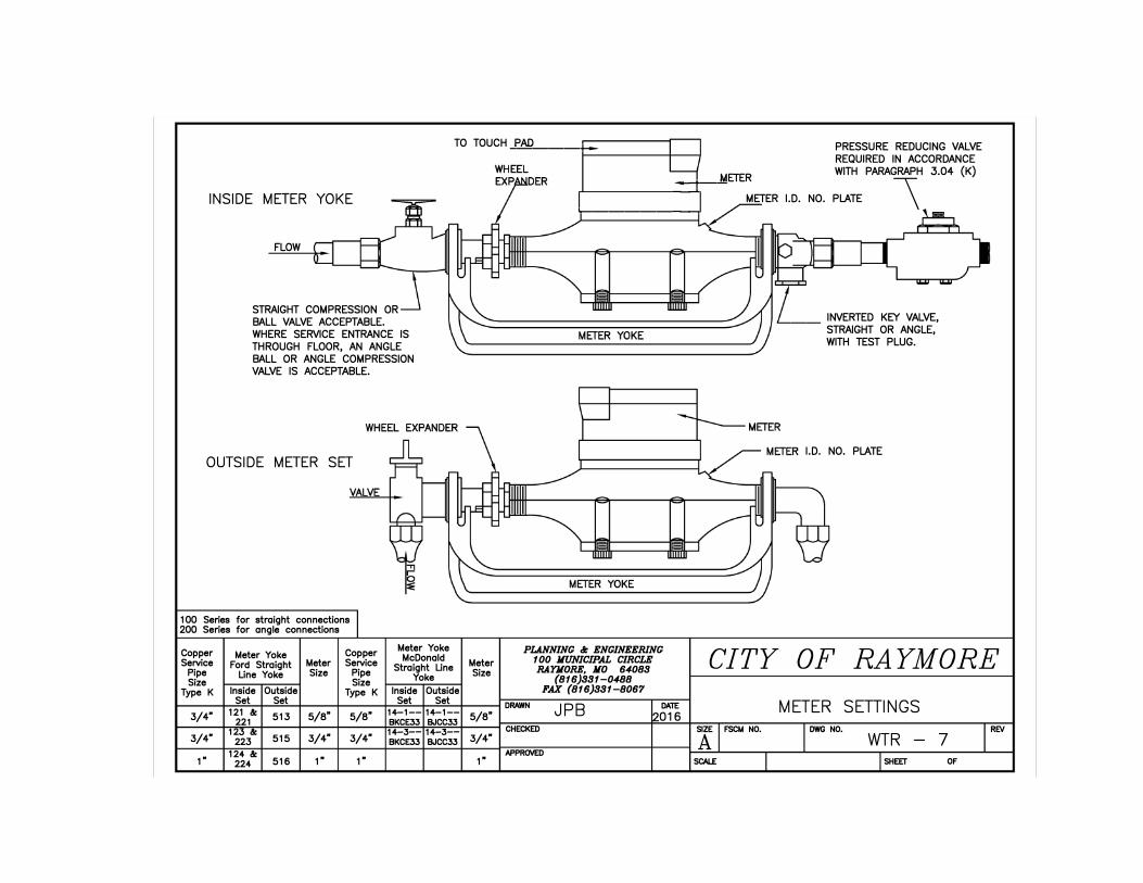
TO TOUCH�P...:.A.=D'----+-- PRESSURE REDUCING VALVE REQUIRED IN ACCORDANCE
INSIDE METER YOKE
FLOW
STRAIGHT COMPRESSION OR BALL VALVE ACCEPTABLE. WHERE SERVICE ENTRANCE IS THROUGH FLOOR, AN ANGLE BALL OR ANGLE COMPRESSION VALVE IS ACCEPTABLE.
OUTSIDE METER SET
100 Series for straight connections 200 Series for angle connections
Copper Meter Yoke Copper Meter Yoke McDonald Service Ford Straight Meter Service Straight Line Pipe Line Yoke Size Pipe
Size Size Yoke
Type K Inside Outside Type K Inside Outside Set Set Set Set
121 &: 14-1--3/4" 513 5/8" 5/8" 14-1--221 BKCE33 BJCC33
3/4" 123 &: 14-3-- 14-3--
223 515 3/4" 3/4" BKCE33 BJCC33
124 &: 1· 224 516 ,. ,.
Meter Size
5/8"
3/4"
,.
METER WITH PARAGRAPH 3.04 (K)
,,__ _____ �::--"' METER I.D. NO. PLATE \
PLANNING 81: ENGINEERING 100 MUNICIPAL CIRCLE RAYMORE, JIO 64088
(816)881-0488FAX (816)881-8067
DRAWN JPB
DATE
016 CHECKED
APPRO\IED
�-- INVERTED KEY VALVE, STRAIGHT OR ANGLE, WITH TEST PLUG.
I.D. NO. PLATE
CITY OF RAYMORE
METER SETIINGS
SIZE FSCM NO. DWG NO. REV
A WTR - 7
SCALE SHEET OF
