s uper idea for ultrasonic inspection
TRANSCRIPT

Super Idea for Ultrasonic Inspection

*EN-12668-1 compliant
Transmitting Probe Receiving Probe
Bottom Wave
Lower End
Upper End
Latcral Wave
WorkpieceAbout TOFD
TOFD (Time of Flight Diffraction): It is an ultrasound inspection
method based on ultrasound diffraction, instead of wave amplitude.
The basic feature is working with T/ R probes.
The Phased Array technology is based on the use of probes
made up of individual elements that can be independently driven.
By electronically shifting the timing of phased array probe elements,
the ultrasound beam can be steered and focused.
About PAUT
Benefits of PAUT
●High Inspection Sensitivity
●Fast Inspection Efficiency
●Strong Inspection Capacity
●Accurate Flaw Positioning
●Visual Inspection Result
Ultrasound Inspection
Ultrasound phased array (PA) and Time Of Flight Diffraction (TOFD), two of the new NDT technologies, have become one important
development trend in current industrial ultrasound flaw detection.
The SUPOR ultrasonic flaw detector represents SIUI’s continuous pursuit and innovation in ultrasound phased array (PA) and Time Of
Flight Diffraction (TOFD) technologies, which incorporate many latest technologies such as ultrasound flaw detection, computer, electronics,
mold tooling and craftwork, with which a perfect combination is achieved on the system.
Phased Array Technology
TOFD Technology
Benefits of TOFD
●Accurate sizing of defects
●Detection is independent of type and orientation of flaws
●Rapid scanning
●High probability of detection

PA with Conventional UT
TOFD with Conventional UT
New generation of ultrasonic flaw detector from SIUI, with modular design and more powerful functions. The SUPOR represents the persistent
fine tradition of SIUI: innovative technology, advanced process, small size, lightweight, powerful functions and easy operation.
Superior Features●Grouping Scanning: It can be divided into up to six groups for one PAUT
probe for different inspections.
●Support two PAUT probes working simultaneously with grouping function.
Modular design: Phased array module (16/32 channels), Phased array +
TOFD module, Multi-channel TOFD module or conventional UT module…
●Simultaneous Inspection of PA & TOFD
●TKY software (Optional)
●Velocity, Sensitivity, Delay, TCG calibration
●Weld simulation
●Scan setup wizard
●Real time A/B/C/D scan
●8.4" touch screen LCD with resolution 800×600 pixels
In Continuous Pursuit of Excellence, SIUI ReleasesPhased Array and TOFD Ultrasonic Flaw Detector
PA & TOFD with Conventional UT
*Specific functions are subject to final order.

Modular Design
Features of Phased Array Module
Ⅱ
System Module PA Module 6-ch TOFD Module
ⅢⅠ
Features of TOFD Module
SUPOR can work with multiple ultrasound imaging modules:
16:64 Phased Array with 2-ch conventional UT module+ optional 1 or 2-ch TOFD function;32:128 Phased Array with 2-ch conventional UT module+ optional 1 or 2-ch TOFD function;
2/4/6 TOFD modules with conventional UT functions...
●16/32 channels for selection
●Bipolar transmit square wave, adjustable transmit voltage and pulse width
●Continuous receive dynamic focusing
●Multiple view display modes
●Data Analysis: image gate dynamic reconstruction
●Multi-channel TOFD function with 2/4/6 channels for selection●0.5MHz~20MHz band width●Negative square wave transmit pulse, adjustable transmit voltage and pulse width
●Data Analysis: Lateral Wave / Bottom Wave Straightening,●Lateral Wave/ Bottom Wave Filtering, Constrast Correction, ●Gain Correction, Flaw Height and Length Measurement
Alarm output port for alarm signal output
Dual axis encoder port for crawler connection
Ethernet port for network data transmission
USB port for connecting USB device or storage
VGA port for VGA monitor or projector connection

Weld Simulation
Weld Simulation is to simulate how phased array
ultrasound propagates in type V, Y or X flat panel butt
weld, so as to help users know the beam coverage status
and finish test process setup.
This function is used to complete testing process design
for the specific testing of work pieces, including the beam
coverage simulation and phased-array imaging parameter
settings. By using this function, the user will find it easier
to analyze, locate flaw signals and make sure each part of
the test pieces meet the industrial welding standards.
Beam Coverage Simulation Wizard
Weld Overlay Simulation
Multi-Group Scanning
Two Groups of B+C Scans
Two Groups of B+D Scans
For one phased array probe, multi groups of element and multi angles
can be applied for scanning at the same time, fully covering the welding
area and enhancing the inspection efficiency.
In SUPOR, one phased array probe can be divided up to six groups for
different inspection.
SUPOR with External Connector
Two phased array probes can work simultaneously
with grouping function to inspect from both sides
of the welding, therefore enhancing the inspection
efficiency and speed.

Wedge Management
Management
Storage ManagementEncoder Management
Probe Management
Scan Setup Wizard
●Smart wizard, which can guide users to finish imaging setup easily and improve
inspection speed.
●Calibration wizard is to calibrate key performance parameters of phased-array,
including velocity, delay, sensitivity and TCG.
●The step-by-step menu guides users to perform all the calibration procedures easily.
Sensitivity Calibration Delay Calibration
Velocity Calibration
●Easy-to-use interface to make work piece, probe, wedge, encoder and storage managements more convenient.
●In the work piece management, the shape of the work piece is simulated and detailed parameters are listed for reference.
●The user may manage probe and wedge parameters via probe and wedge management.
●Follow the wizard, the user can finish encoder simple operation, calibration and test quickly.
●Parameters, screenshot and data can be easily managed in the storage management to enhance
the inspection efficiency.
Work Piece Management
TCG Calibration

SuporUp PC Software
SuporUp is a PC-based software for
●Checking data file: check the phased array or TOFD files transferred from SUPOR.
●Measuring data analysis: measure and analyze the phased array or TOFD files.
●Generating measurement reports: input the file information and the measurement result of phased array or TOFD files to a specific
file to generate the test report.
Phased Array MeasurementTOFD File Measurement
Multiple B-scan Multiple A+B Scan
SuporUp provides several display modes for selection; users can use different display modes during inspection or analysis with flexibility.
Change the size and position of the region of interest, and the software will re-construct C/D scan images automatically.
For phased array files, SuporUp can
●Perform width, height and rectangle measurement on the phased-array B/C/D image.
●Perform height, sound path, vertical distance and horizontal distance measurement on the A-scan echo.
For TOFD files, SuporUp can
●Perform length measurement, straightening, filter, recovery, local zoom, SAFT,
contrast adjustment and gain post processing on the TOFD image.
Detection echoes, curves or parameters may be losslessly stored to
SuporUp facilitating report editing and data management.
Screenshot and detailed info can be transferred to Microsoft Word for
customized reporting. The user can add company logos and inspection
specific information including all relevant inspection settings to make a
full report.
Angle step
Focus
Scan angle(Linear)Channel 2
CalibrationProbe InfoProbe model
Frequency
Pitch
Element num
Probe length
Probe width
Probe heightWedge InfoWedge model
Angle
First element height
First element x
Vel
Wedge length
Wedge width
Wedge height
Setup InfoScan depth
Display delay
Pulse voltage
Pulse freq
Pulse power
PRF
Receive freq
Gain
Scan line num / frame
Echo type
Material vel
Scan type
Start element
End element
Linear step
Aperture
Start angle(Sector)
End angle(Sector)
Angle step
Focus
Scan angle(Linear)Images
Measurement
Remark
Operator
Signature
Date:
Ultrasonic Test ReportCompany
Workpiece SNSpecs Material SurfaceMethod CouplingStandard Class DateFile Info
File name File typeMachine Info
Machine Machine SNModule Module SNSoftware version Hardware versionGroupNumScanning Info
Frame num Scan modeScan time step Scan encode step
Scan encoder XMpp Scan encoder YMppEncoder Name
Channel 1Calibration
Probe InfoProbe model Frequency
Pitch Element numProbe length Probe widthProbe height
Wedge InfoWedge model Angle
First element height First element xVel Wedge length
Wedge width Wedge heightSetup InfoScan depth Display delay
Pulse voltage Pulse freqPulse power PRFReceive freq Gain
Scan line num / frame Echo typeMaterial vel Scan typeStart element End elementLinear step Aperture
Start angle(Sector) End angle(Sector)Angle step Focus
Scan angle(Linear)Channel 2
CalibrationProbe Info
Probe model FrequencyPitch Element num
Probe length Probe widthProbe height
Wedge InfoWedge model Angle
First element height First element x
Vel
Wedge length
Wedge width
Wedge height
Setup InfoScan depth
Display delay
Pulse voltage
Pulse freq
Pulse power
PRF
Receive freq
Gain
Scan line num / frame
Echo type
Material vel
Scan type
Start element
End element
Linear step
Aperture
Start angle(Sector)
End angle(Sector)
Angle step
Focus
Scan angle(Linear)
Images
Measurement
Remark
Operator
Signature
Date:
Display Mode
Management
Reporting
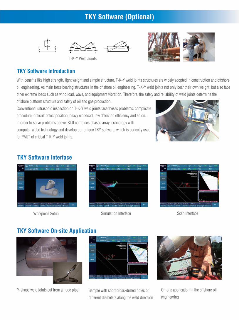
TKY Software (Optional)
With benefits like high strength, light weight and simple structure, T-K-Y weld joints structures are widely adopted in construction and offshore
oil engineering. As main force bearing structures in the offshore oil engineering, T-K-Y weld joints not only bear their own weight, but also face
other extreme loads such as wind load, wave, and equipment vibration. Therefore, the safety and reliability of weld joints determine the
offshore platform structure and safety of oil and gas production.
Conventional ultrasonic inspection on T-K-Y weld joints face theses problems: complicate
procedure, difficult defect position, heavy workload, low defection efficiency and so on.
In order to solve problems above, SIUI combines phased array technology with
computer-aided technology and develop our unique TKY software, which is perfectly used
for PAUT of critical T-K-Y weld joints.
T-K-Y Weld Joints
TKY Software Introduction
TKY Software Interface
TKY Software On-site Application
Workpiece Setup Simulation Interface Scan Interface
Y-shape weld joints cut from a huge pipe Sample with short cross-drilled holes of
different diameters along the weld direction
On-site application in the offshore oil
engineering
●Grouping Scanning: It can be divided into up to six groups for one PAUT
probe for different inspections.
●Support two PAUT probes working simultaneously with grouping function.
Modular design: Phased array module (16/32 channels), Phased array +
TOFD module, Multi-channel TOFD module or conventional UT module…
●Simultaneous Inspection of PA & TOFD
●TKY software (Optional)
●Velocity, Sensitivity, Delay, TCG calibration
●Weld simulation
●Scan setup wizard
●Real time A/B/C/D scan
●8.4" touch screen LCD with resolution 800×600 pixels
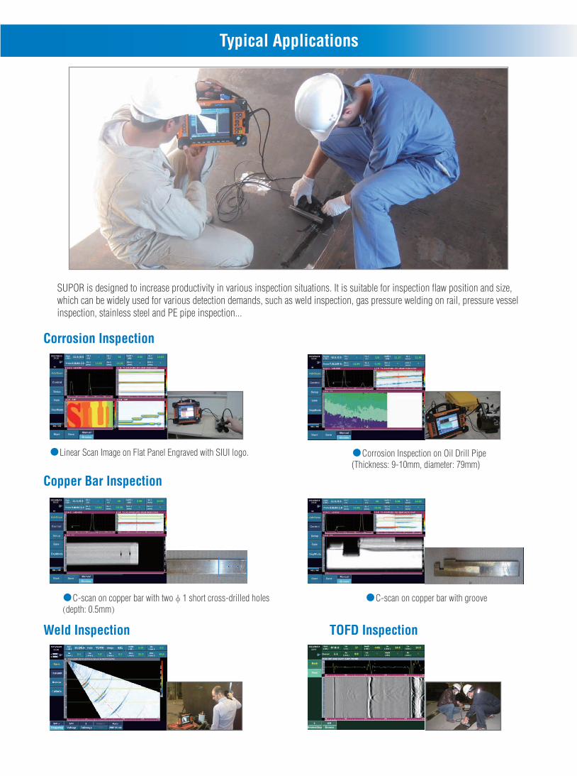
Typical Applications
SUPOR is designed to increase productivity in various inspection situations. It is suitable for inspection flaw position and size,which can be widely used for various detection demands, such as weld inspection, gas pressure welding on rail, pressure vessel inspection, stainless steel and PE pipe inspection...
Corrosion Inspection
●Corrosion Inspection on Oil Drill Pipe (Thickness: 9-10mm, diameter: 79mm)
●Linear Scan Image on Flat Panel Engraved with SIUI logo.
●C-scan on copper bar with twoφ1 short cross-drilled holes(depth: 0.5mm)
●C-scan on copper bar with groove
Weld Inspection TOFD Inspection
Copper Bar Inspection
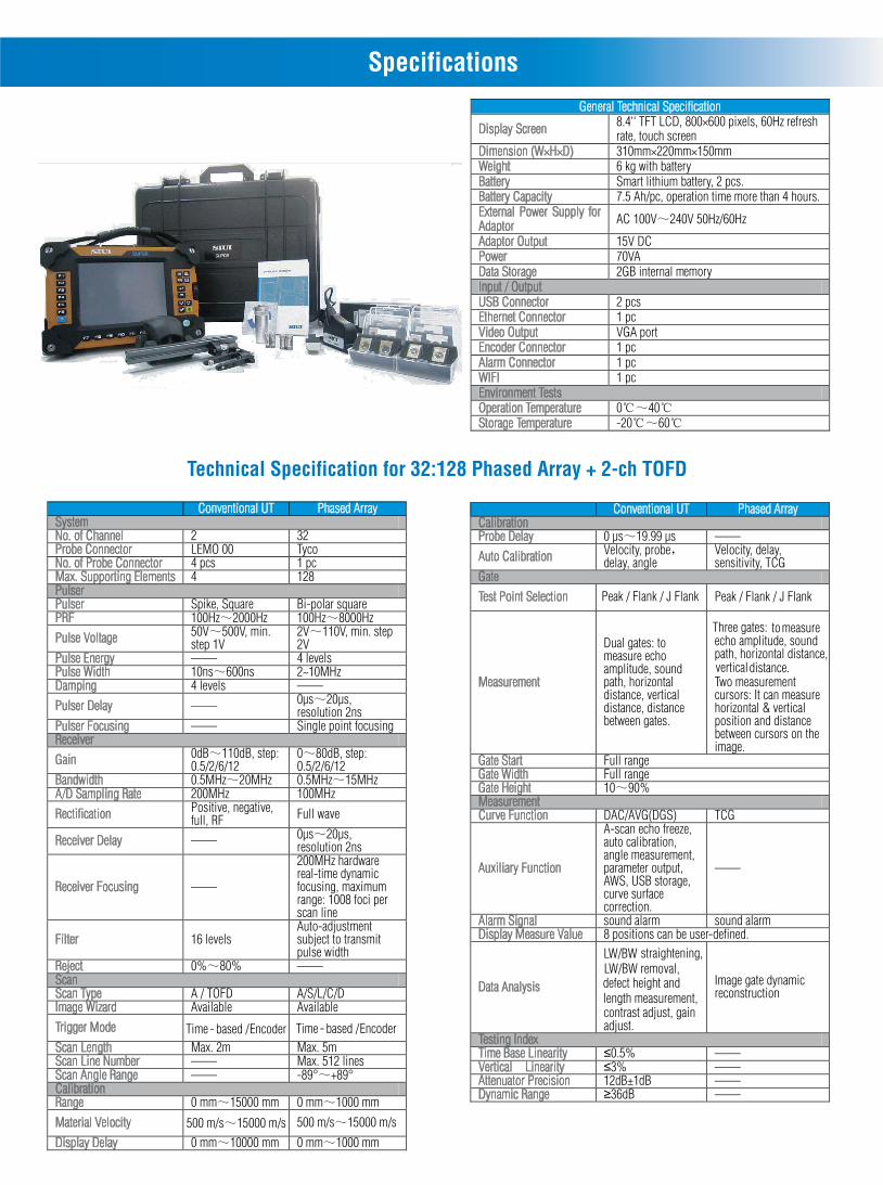
Specifications
Technical Specification for 32:128 Phased Array + 2-ch TOFD
General Technical Specification
Display Screen 8.4'' TFT LCD, 800×600 pixels, 60Hz refresh rate, touch screen
Dimension (W×H×D) 310mm×220mm×150mmWeight 6 kg with batteryBattery Smart lithium battery, 2 pcs.Battery Capacity 7.5 Ah/pc, operation time more than 4 hours.External Power Supply for Adaptor AC 100V~240V 50Hz/60Hz
Adaptor Output 15V DCPower 70VAData Storage 2GB internal memoryInput / OutputUSB Connector 2 pcsEthernet Connector 1 pcVideo Output VGA portEncoder Connector 1 pcAlarm Connector 1 pcWIFI 1 pcEnvironment TestsOperation Temperature 0℃~40℃Storage Temperature -20℃~60℃
Conventional UT Phased ArraySystemNo. of Channel 2 32Probe Connector LEMO 00 TycoNo. of Probe Connector 4 pcs 1 pcMax. Supporting Elements 4 128PulserPulser Spike, Square Bi-polar squarePRF 100Hz~2000Hz 100Hz~8000Hz
Pulse Voltage 50V~500V, min. step 1V
2V~110V, min. step 2V
Pulse Energy —— 4 levelsPulse Width 10ns~600ns 2~10MHzDamping 4 levels ——
Pulser Delay —— 0µs~20µs, resolution 2ns
Pulser Focusing —— Single point focusingReceiver
Gain 0dB~110dB, step: 0.5/2/6/12
0~80dB, step: 0.5/2/6/12
Bandwidth 0.5MHz~20MHz 0.5MHz~15MHzA/D Sampling Rate 200MHz 100MHz
Rectification Positive, negative, full, RF Full wave
Receiver Delay —— 0µs~20µs, resolution 2ns
Receiver Focusing ——
200MHz hardware real-time dynamic focusing, maximum range: 1008 foci per scan line
Filter 16 levelsAuto-adjustment subject to transmit pulse width
Reject 0%~80% ——ScanScan Type A / TOFD A/S/L/C/D Image Wizard Available Available
Trigger Mode Time - based / EncoderScan Length Max. 2m Max. 5mScan Line Number —— Max. 512 linesScan Angle Range —— -89°~+89°CalibrationRange 0 mm~15000 mm 0 mm~1000 mm
Material Velocity 500 m/s~15000 m/s
Display Delay 0 mm~10000 mm 0 mm~1000 mm
Conventional UT Phased ArrayCalibrationProbe Delay 0 µs~19.99 µs ——
Auto Calibration Velocity, probe,delay, angle
Velocity, delay, sensitivity, TCG
Gate
Test Point Selection Peak / Flank / J Flank
Measurement
Dual gates: to measure echo amplitude, sound path, horizontal distance, vertical distance, distance between gates.
Three gates: to measure echo amplitude, sound path, horizontal distance, vertical distance.Two measurement cursors: It can measure horizontal & vertical position and distance between cursors on the image.
Gate Start Full rangeGate Width Full rangeGate Height 10~90%MeasurementCurve Function DAC/AVG(DGS) TCG
Auxiliary Function
A-scan echo freeze, auto calibration, angle measurement, parameter output, AWS, USB storage, curve surface correction.
——
Alarm Signal sound alarm sound alarmDisplay Measure Value 8 positions can be user-defined.
Data Analysis
LW/BW straightening, LW/BW removal, defect height and length measurement, contrast adjust, gain adjust.
Image gate dynamic reconstruction
Testing IndexTime Base Linearity ≤0.5% ——Vertical Linearity ≤3% ——Attenuator Precision 12dB±1dB ——Dynamic Range ≥36dB ——
Peak / Flank / J Flank
Time - based / Encoder
500 m/s~15000 m/s

Technical Specification for 6-ch TOFD or 6-ch Conventional UT
Imaging Mode Conventional UTSystemChannel 6Probe Connector Type LEMO 00 Probe Connector Number
12 pcs
Max. Supporting Elements
12
PulserPulser Spike, squarePRF 100Hz~2000HzPulse Voltage 50V~500V, min. step 50VPulse Width 10ns~600nsDamping 4 levelsReceiverGain 0dB~110dB, step: 0.5/2/6/12 Bandwidth 0.5MHz~25MHzA/D Sampling Rate 200MHzRectification Positive, Negative, Full, RFFilter 16 levels availableReject 0%~80%ScanScan Type A/TOFDImage Wizard AvailableTrigger Mode Time-based / EncoderScan Length Max. 2mCalibrationRange 12 mm~15000 mmMaterial Velocity 1000 m/s~10000 m/sDisplay Delay -10 mm~10000 mmProbe Delay 0 µs~200 µsAuto Calibration Velocity, probe delayManual Calibration Velocity, probe delayGateTest Point Selection Peak / flank / J flankMeasurement Dual gates: to measure echo amplitude, sound path, horizontal distance, vertical distance, distance between gates. Gate Start Full rangeGate Width Full rangeGate Height 10~90%MeasurementCurve Function DAC
Auxiliary Function A-scan echo freeze, auto calibration, angle measurement, peak memory, parameter output, AWS D1.1/D1.5, USB storage, curve surface correction.
Alarm Signal Signal and sound alarm Display Measure Value 8 positions can be user-defined. Data Analysis LW/ BW straightening, LW/ BW removal, defect height and length measurement, contrast adjust, gain adjustTesting IndexTime base Linearity ≤0.5%Vertical Linearity ≤3%Attenuator Precision 12dB±1dBDynamic Range ≥36dB
SoftwareSuporUp PC SoftwareBasic version and advanced version available. Basic version function: For Phased Array or TOFD measurement, analysis, report generation.TKY Software (Optional)For PAUT of critical T-K-Y weld joints
Specifications

DCY2.781.EN.SUPOR. CY/7C05Specifications and appearance are subject to change without prior notice.
Shantou Institute of Ultrasonic Instruments Co., Ltd.
Add: #77, Jinsha Road, Shantou 515041, Guangdong, ChinaTel: +86-754-88250150 Fax: +86-754-88251499E-mail: [email protected] Website: http://www.siui.com