s110 softdevice specification - nordic semiconductor...
TRANSCRIPT

Copyright © 2014 Nordic Semiconductor ASA. All rights reserved.Reproduction in whole or in part is prohibited without the prior written permission of the copyright holder.
S110 nRF51Bluetooth® low energy Peripheral SoftDevice
SoftDevice Specification v2.0
Key Features
• Bluetooth® 4.1 compliant low energy single-mode protocol stack
• Link layer• L2CAP, ATT, and SM protocols• GATT, GAP, and L2CAP• Concurrent Peripheral and Broadcaster roles• GATT Client and Server• Full SMP support including MITM and OOB pairing
• Complementary nRF51 SDK including Bluetooth profiles and example applications
• Master Boot Record for over-the-air device firmware update• Memory isolation between application and protocol stack for
robustness and security• Thread-safe supervisor-call based API• Asynchronous, event-driven behavior• No RTOS dependency
• Any RTOS can be used• No link-time dependencies
• Standard ARM® Cortex™-M0 project configuration for application development
• Support for multiprotocol operation concurrent with Bluetooth low energy connections and non-concurrently
• Concurrent multiprotocol timeslot API• Alternate protocol stack running in application space
Applications
• Computer peripherals and I/O devices• Mouse• Keyboard• Multi-touch trackpad
• Interactive entertainment devices• Remote control• 3D glasses• Gaming controller
• Personal Area Networks• Health and fitness sensor and monitor
devices• Medical devices• Key fobs and wrist watches
• Remote control toys• Home automation
S110 nRF51 SoftDevice Specification v2.0
Page 2
Liability disclaimerNordic Semiconductor ASA reserves the right to make changes without further notice to the product to improve reliability, function or design. Nordic Semiconductor ASA does not assume any liability arising out of the application or use of any product or circuits described herein.
Life support applicationsNordic Semiconductor’s products are not designed for use in life support appliances, devices, or systems where malfunction of these products can reasonably be expected to result in personal injury. Nordic Semiconductor ASA customers using or selling these products for use in such applications do so at their own risk and agree to fully indemnify Nordic Semiconductor ASA for any damages resulting from such improper use or sale.
Contact detailsFor your nearest distributor, please visit http://www.nordicsemi.com.Information regarding product updates, downloads, and technical support can be accessed through your My Page account on our homepage.
Main office:
Phone: +47 72 89 89 00Fax: +47 72 89 89 89
Otto Nielsens veg 127052 TrondheimNorway
Mailing address: Nordic SemiconductorP.O. Box 23367004 TrondheimNorway

S110 nRF51 SoftDevice Specification v2.0
Document Status
Revision History
Status Description
v0.5 This specification contains target specifications for product development.
v0.7 This specification contains preliminary data; supplementary data may be published from Nordic Semiconductor ASA later.
v1.0 This specification contains final product specifications. Nordic Semiconductor ASA reserves the right to make changes at any time without notice in order to improve design and supply the best possible product.
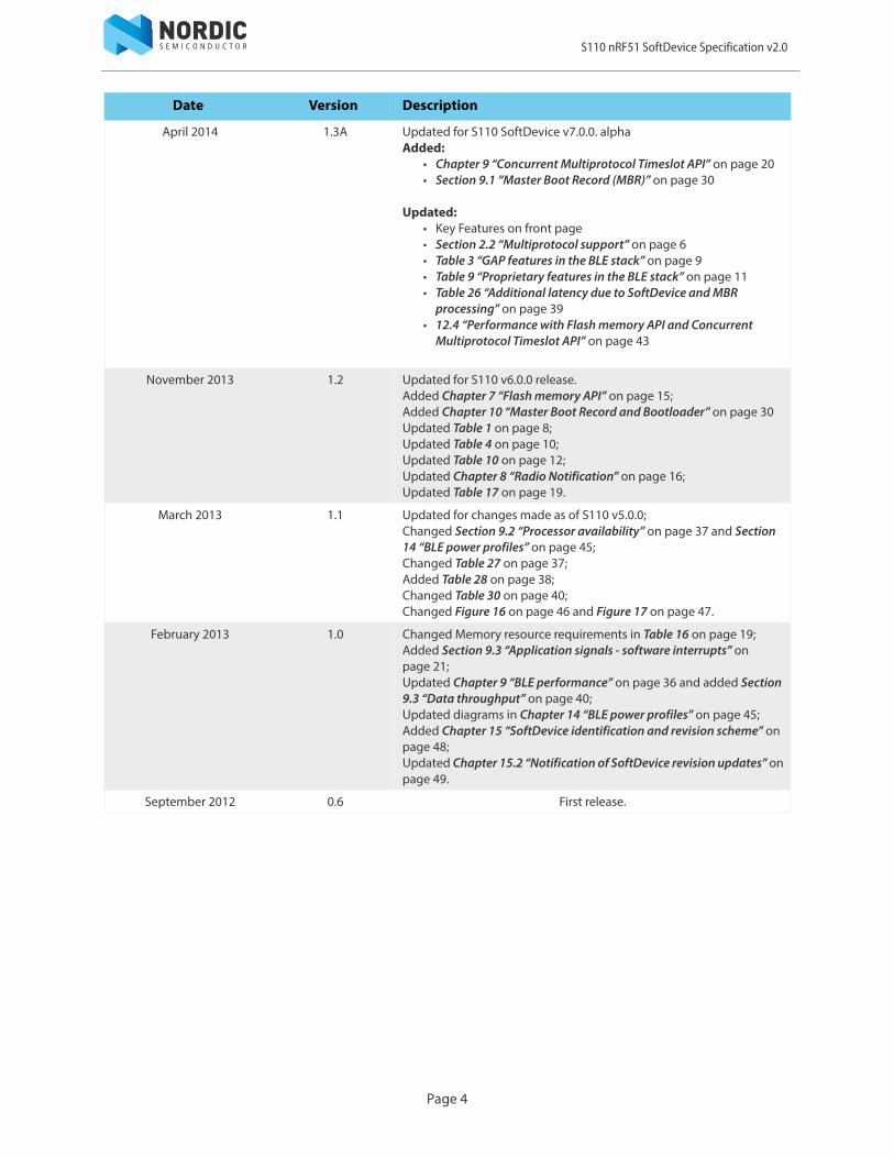
Date Version Description
February 2015 2.0 Updated for S110 SoftDevice v8.0.0.Added:
• Chapter 6 “SoftDevice information structure” on page 14• Section 11.1 “Attribute Table size” on page 33• Appendix A "SoftDevice architecture" on page 50
Updated:• Section 3.1 “Profile and service support” on page 8• Section 3.2 “Bluetooth low energy features” on page 9• Chapter 8 “Radio Notification” on page 16• Section 10.2 “Bootloader” on page 30• Section 10.3 “Master Boot Record (MBR) and SoftDevice reset
behavior” on page 31• Section 10.4 “Master Boot Record (MBR) and SoftDevice
initialization” on page 32• Section 11.2 “Memory resource map and usage” on page 34• Section 12.3 “BLE peripheral performance” on page 41• Chapter 13 “BLE data throughput” on page 44• Chapter 14 “BLE power profiles” on page 45
June 2014 1.3 Updated for S110 SoftDevice v7.0.0.Added:
• Chapter 11.7 “External requirements” on page 38
Updated:• Key Features on front page• Section 1.1 “Documentation” on page 5• Section 2.2 “Multiprotocol support” on page 6• Section 3.1 “Profile and service support” on page 8• Section 3.2 “Bluetooth low energy features” on page 9• Chapter 4 “SoC library” on page 12• Chapter 5 “SoftDevice Manager” on page 13• Chapter 7 “Flash memory API” on page 15• Section 9.6 “Multiprotocol timeslot API” on page 22• Section 9.1 “Master Boot Record (MBR)” on page 30• Section 11.2 “Memory resource map and usage” on page 34
Page 3
S110 nRF51 SoftDevice Specification v2.0
April 2014 1.3A Updated for S110 SoftDevice v7.0.0. alphaAdded:
• Chapter 9 “Concurrent Multiprotocol Timeslot API” on page 20• Section 9.1 “Master Boot Record (MBR)” on page 30
Updated:• Key Features on front page• Section 2.2 “Multiprotocol support” on page 6• Table 3 “GAP features in the BLE stack” on page 9• Table 9 “Proprietary features in the BLE stack” on page 11• Table 26 “Additional latency due to SoftDevice and MBR
processing” on page 39• 12.4 “Performance with Flash memory API and Concurrent
Multiprotocol Timeslot API” on page 43
November 2013 1.2 Updated for S110 v6.0.0 release.Added Chapter 7 “Flash memory API” on page 15;Added Chapter 10 “Master Boot Record and Bootloader” on page 30Updated Table 1 on page 8;Updated Table 4 on page 10;Updated Table 10 on page 12;Updated Chapter 8 “Radio Notification” on page 16;Updated Table 17 on page 19.
March 2013 1.1 Updated for changes made as of S110 v5.0.0;Changed Section 9.2 “Processor availability” on page 37 and Section 14 “BLE power profiles” on page 45; Changed Table 27 on page 37;Added Table 28 on page 38;Changed Table 30 on page 40;Changed Figure 16 on page 46 and Figure 17 on page 47.
February 2013 1.0 Changed Memory resource requirements in Table 16 on page 19; Added Section 9.3 “Application signals - software interrupts” on page 21; Updated Chapter 9 “BLE performance” on page 36 and added Section 9.3 “Data throughput” on page 40; Updated diagrams in Chapter 14 “BLE power profiles” on page 45; Added Chapter 15 “SoftDevice identification and revision scheme” on page 48; Updated Chapter 15.2 “Notification of SoftDevice revision updates” on page 49.
September 2012 0.6 First release.
Date Version Description
Page 4

S110 nRF51 SoftDevice Specification v2.0
Page 5
1 IntroductionThe S110 SoftDevice is a Bluetooth® low energy (BLE) Peripheral protocol stack solution. It integrates a low energy controller and host, and provides a full and flexible Application Programming Interface (API) for building Bluetooth low energy System on Chip (SoC) solutions.
This document contains information about the SoftDevice features and performance.
Note: The SoftDevice features and performance are subject to change between revisions of this document. See Section 15.2 “Notification of SoftDevice revision updates” on page 49 for more information. This specification outlines the supported features of a production level SoftDevice. Alpha and beta versions of the SoftDevice may not support all features. To find information on any limitations or omissions, see the SoftDevice release notes, which will contain a detailed summary of the release status.
1.1 DocumentationBelow is a list of the core documentation for the SoftDevice.
Document Description
Appendix A: SoftDevice Architecture
Essential reading for understanding the resource usage and performance related chapters of this document.
nRF51822 Product Specification (PS)
Contains a description of the hardware, modules, and electrical specifications specific to the nRF51822 chip.
nRF51822 Product Anomaly Notification (PAN)
Contains information on anomalies related to the nRF51822 chip.
nRF51 Series Compatibility Matrix
Compatibility and relations between nRF51 IC revisions, SoftDevices and SoftDevice Specifications, SDKs, development kits, documentation, and QDIDs.
Bluetooth Core Specification
The Bluetooth Core Specification version 4.1, Volumes 1, 3, 4, and 6 describes Bluetooth terminology which is used throughout the SoftDevice Specification.

S110 nRF51 SoftDevice Specification v2.0
Page 6
2 Product overviewThis section provides an overview of the SoftDevice.
2.1 SoftDeviceThe SoftDevice is a precompiled and linked binary software implementing a Bluetooth 4.1 low energy protocol stack for the nRF51 series of chips. See the nRF51 Series Compatibility Matrix for SoftDevice/chip compatibility information.
The Application Programming Interface (API) is a set of standard C language functions and data types that give the application complete compiler and linker independence from the SoftDevice implementation.
The SoftDevice enables the application programmer to develop their code as a standard ARM® Cortex™-M0 project without needing to integrate with proprietary chip-vendor software frameworks. This means that any ARM® Cortex™-M0 compatible toolchain can be used to develop Bluetooth low energy applications with the SoftDevice.
Figure 1 System on Chip application with the SoftDevice
The SoftDevice can be programmed onto compatible nRF51 Series chips during both development and production.
2.2 Multiprotocol supportThe SoftDevice supports both non-concurrent and fully concurrent multiprotocol implementations. For non-concurrent operation, a proprietary 2.4 GHz protocol can be implemented in the application program area and can access all hardware resources when the SoftDevice is disabled. For concurrent multiprotocol operation, with a proprietary protocol running concurrently with the SoftDevice protocol(s), see Chapter 9 “Concurrent Multiprotocol Timeslot API” on page 20.
CMSIS
nRF API
Application – Profiles and Services
App-Specific peripheral
drivers
nRF51 HW
nRF SoftDevice
Protocol Stack
SoftDevice Manager
SoC Library
| Protocol API (SV Calls)

S110 nRF51 SoftDevice Specification v2.0
3 Bluetooth low energy protocol stackThe Bluetooth 4.1 compliant low energy Host and Controller embedded in the SoftDevice are fully qualified with multi-role support (Peripheral and Broadcaster). The API is defined above the Generic Attribute Protocol (GATT), Generic Access Profile (GAP), and Logical Link Control and Adaptation Protocol (L2CAP). The SoftDevice allows applications to implement standard Bluetooth low energy profiles as well as proprietary use case implementations.
The nRF51 Software Development Kit (SDK) complements the BLE protocol stack with Service and Profile implementations. Single-mode System on Chip (SoC) applications are enabled by the full BLE protocol stack and nRF51 series integrated circuit (IC).
Figure 2 SoftDevice stack architecture
nRF51 SoC
SoftDevice
Host
Controller
Physical Layer (PHY)
Generic Attribute Profile (GATT)
Attribute Protocol (ATT)
Logical Link Control and Adaptation Layer Protocol (L2CAP)
Link Layer (LL)
Security Manager (SM)
Generic Access Profile(GAP)
ApplicationProfiles and Services
Page 7

S110 nRF51 SoftDevice Specification v2.0
3.1 Profile and service supportTable 1 lists the profiles and services adopted by the Bluetooth Special Interest Group at the time of publication of this document. The SoftDevice supports all of these as well as additional proprietary profiles.
Table 1 Supported profiles and services
Note: Examples for selected profiles and services are available in the nRF51 SDK. See the SDK documentation for details.
Adopted Profile Adopted Services
HID over GATTHIDBatteryDevice Information
Heart RateHeart RateDevice Information
ProximityLink LossImmediate AlertTX Power
Blood Pressure Blood Pressure Device Information
Health Thermometer Health ThermometerDevice Information
Glucose GlucoseDevice Information
Phone Alert Status Phone Alert Status
Alert Notification Alert Notification
TimeCurrent TimeNext DST ChangeReference Time Update
Find Me Immediate Alert
Cycling Speed and CadenceCycling Speed and CadenceDevice information
Running Speed and CadenceRunning Speed and CadenceDevice Information
Location and Navigation Location and Navigation
Cycling Power Cycling Power
Scan Parameters Scan Parameters
Weight Scale Weight ScaleBody CompositionUser DataDevice Information
Continuous Glucose Monitoring Continuous Glucose MonitoringBond ManagementDevice Information
Environmental Sensing Environmental Sensing
Page 8
S110 nRF51 SoftDevice Specification v2.0
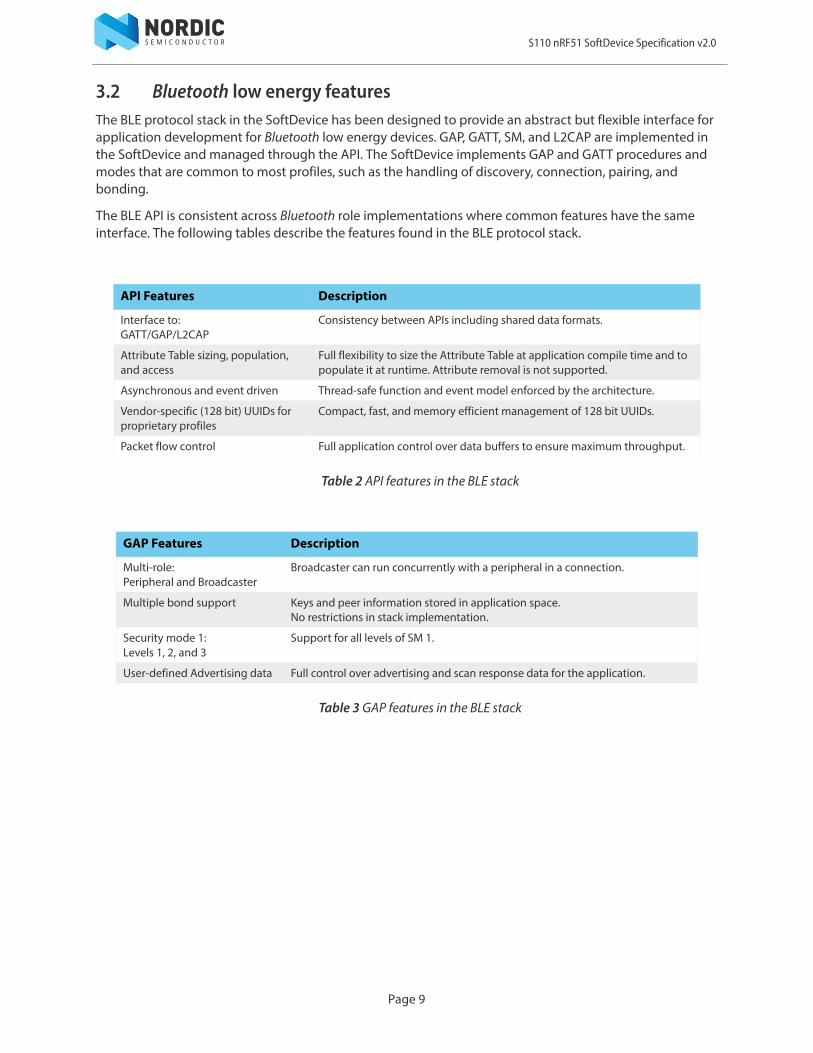
3.2 Bluetooth low energy featuresThe BLE protocol stack in the SoftDevice has been designed to provide an abstract but flexible interface for application development for Bluetooth low energy devices. GAP, GATT, SM, and L2CAP are implemented in the SoftDevice and managed through the API. The SoftDevice implements GAP and GATT procedures and modes that are common to most profiles, such as the handling of discovery, connection, pairing, and bonding.
The BLE API is consistent across Bluetooth role implementations where common features have the same interface. The following tables describe the features found in the BLE protocol stack.
Table 2 API features in the BLE stack
Table 3 GAP features in the BLE stack
API Features Description
Interface to:GATT/GAP/L2CAP
Consistency between APIs including shared data formats.
Attribute Table sizing, population, and access
Full flexibility to size the Attribute Table at application compile time and to populate it at runtime. Attribute removal is not supported.
Asynchronous and event driven Thread-safe function and event model enforced by the architecture.
Vendor-specific (128 bit) UUIDs for proprietary profiles
Compact, fast, and memory efficient management of 128 bit UUIDs.
Packet flow control Full application control over data buffers to ensure maximum throughput.
GAP Features Description
Multi-role:Peripheral and Broadcaster
Broadcaster can run concurrently with a peripheral in a connection.
Multiple bond support Keys and peer information stored in application space.No restrictions in stack implementation.
Security mode 1:Levels 1, 2, and 3
Support for all levels of SM 1.
User-defined Advertising data Full control over advertising and scan response data for the application.
Page 9
S110 nRF51 SoftDevice Specification v2.0
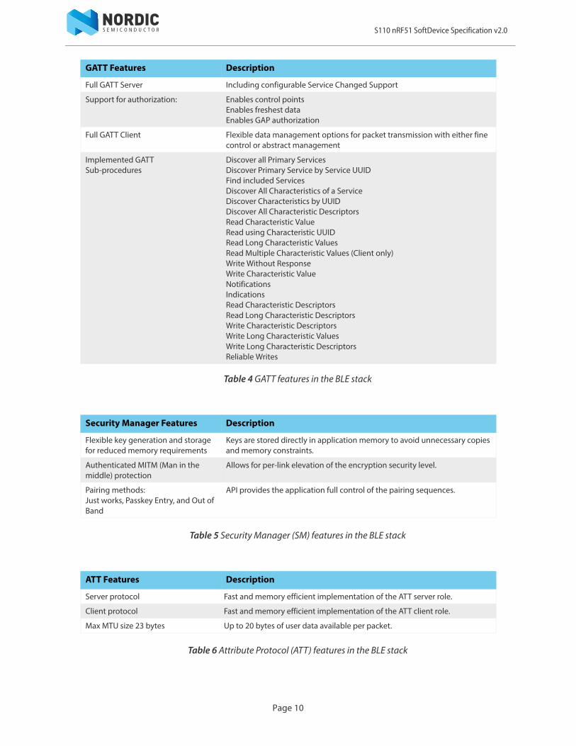
Table 4 GATT features in the BLE stack
Table 5 Security Manager (SM) features in the BLE stack
Table 6 Attribute Protocol (ATT) features in the BLE stack
GATT Features Description
Full GATT Server Including configurable Service Changed Support
Support for authorization: Enables control pointsEnables freshest dataEnables GAP authorization
Full GATT Client Flexible data management options for packet transmission with either fine control or abstract management
Implemented GATT Sub-procedures
Discover all Primary ServicesDiscover Primary Service by Service UUIDFind included ServicesDiscover All Characteristics of a ServiceDiscover Characteristics by UUIDDiscover All Characteristic DescriptorsRead Characteristic ValueRead using Characteristic UUIDRead Long Characteristic ValuesRead Multiple Characteristic Values (Client only)Write Without ResponseWrite Characteristic ValueNotificationsIndicationsRead Characteristic DescriptorsRead Long Characteristic DescriptorsWrite Characteristic DescriptorsWrite Long Characteristic ValuesWrite Long Characteristic DescriptorsReliable Writes
Security Manager Features Description
Flexible key generation and storage for reduced memory requirements
Keys are stored directly in application memory to avoid unnecessary copies and memory constraints.
Authenticated MITM (Man in the middle) protection
Allows for per-link elevation of the encryption security level.
Pairing methods:Just works, Passkey Entry, and Out of Band
API provides the application full control of the pairing sequences.
ATT Features Description
Server protocol Fast and memory efficient implementation of the ATT server role.
Client protocol Fast and memory efficient implementation of the ATT client role.
Max MTU size 23 bytes Up to 20 bytes of user data available per packet.
Page 10
S110 nRF51 SoftDevice Specification v2.0
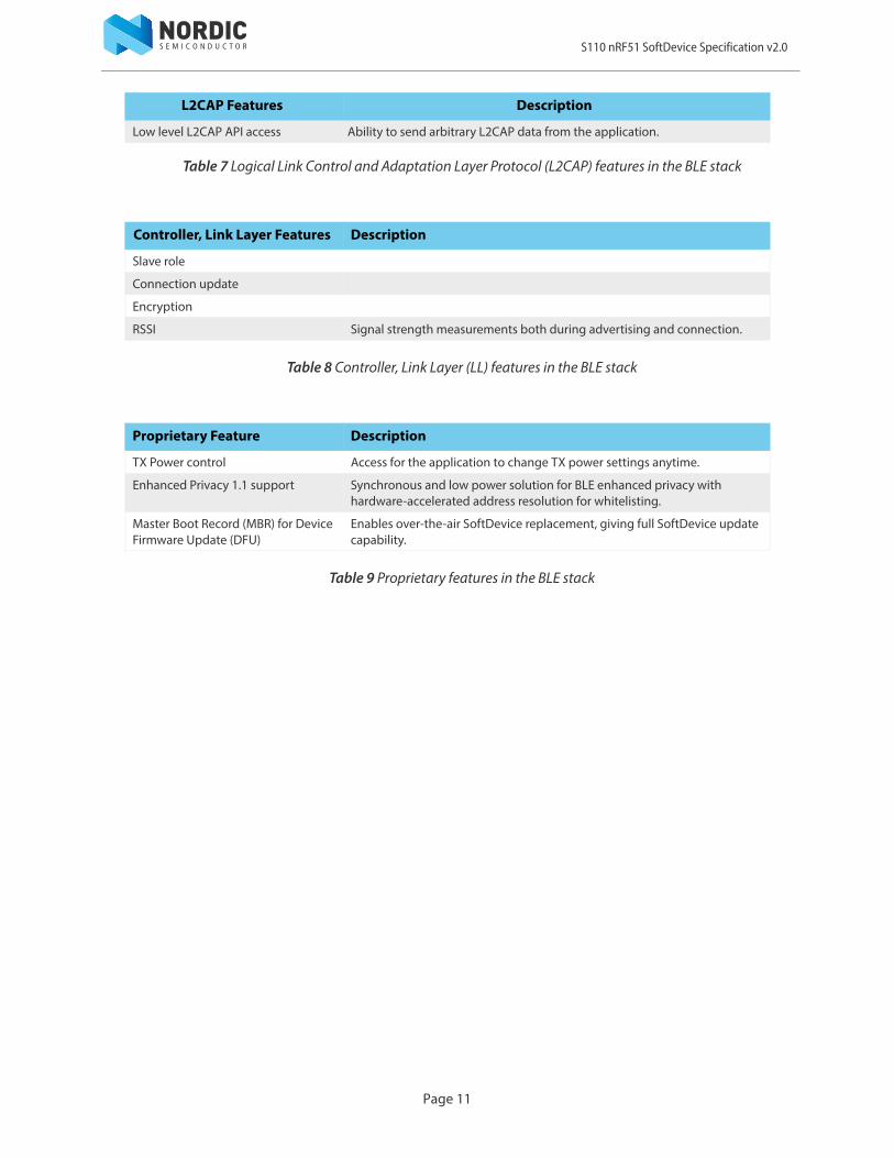
Table 7 Logical Link Control and Adaptation Layer Protocol (L2CAP) features in the BLE stack
Table 8 Controller, Link Layer (LL) features in the BLE stack
Table 9 Proprietary features in the BLE stack
L2CAP Features Description
Low level L2CAP API access Ability to send arbitrary L2CAP data from the application.
Controller, Link Layer Features Description
Slave role
Connection update
Encryption
RSSI Signal strength measurements both during advertising and connection.
Proprietary Feature Description
TX Power control Access for the application to change TX power settings anytime.
Enhanced Privacy 1.1 support Synchronous and low power solution for BLE enhanced privacy with hardware-accelerated address resolution for whitelisting.
Master Boot Record (MBR) for Device Firmware Update (DFU)
Enables over-the-air SoftDevice replacement, giving full SoftDevice update capability.
Page 11

S110 nRF51 SoftDevice Specification v2.0
Page 12
4 SoC libraryThe following features ensure that the Application and SoftDevice can coexist with safe sharing of common SoC resources.
Table 10 System on Chip features
Feature Description
Mutex The SoftDevice implements atomic mutex acquire and release operations that are safe for the application to use. Use this mutex to avoid disabling global interrupts in the application, because disabling global interrupts will interfere with the SoftDevice and may lead to dropped packets or lost connections.
NVIC Gives the application access to all NVIC features without corrupting SoftDevice configurations.
Rand Provides random numbers from the hardware random number generator.
Power Access to POWER block configuration while the SoftDevice is enabled:• Access to RESETREAS register• Set power modes• Configure power fail comparator• Control RAM block power• Use general purpose retention register• Configure DC/DC converter state:
• DISABLED• ENABLED
Clock Access to CLOCK block configuration while the SoftDevice is enabled. Allows the HFCLK Crystal Oscillator source to be requested by the application.
Wait for event Simple power management call for the application to use to enter a sleep or idle state and wait for an event.
PPI Configuration interface for PPI channels and groups reserved for an application.
Concurrent Multiprotocol Timeslot API
Schedule other radio protocol activity, or periods of radio inactivity. See Chapter 9 “Concurrent Multiprotocol Timeslot API” on page 20.
Radio notification Configure Radio Notification signals on ACTIVE and/or nACTIVE.See Chapter 8 “Radio Notification” on page 16.
Block encrypt (ECB) Safe use of 128 bit AES encrypt HW accelerator.
Event API Fetch asynchronous events generated by the SoC library.
Flash memory API Application access to flash write, erase, and protect. Can be safely used during all protocol stack states. See Chapter 6 “Flash memory API” on page 15.
Temperature Application access to the temperature sensor.
S110 nRF51 SoftDevice Specification v2.0
Page 13
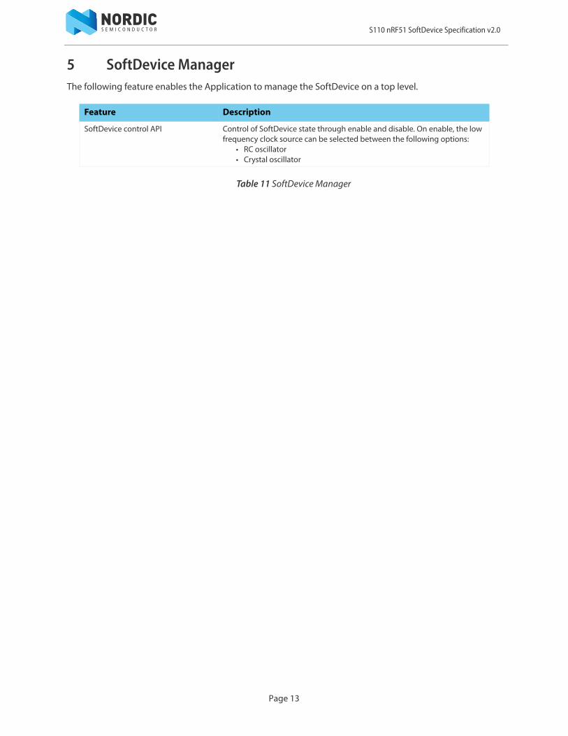
5 SoftDevice ManagerThe following feature enables the Application to manage the SoftDevice on a top level.
Table 11 SoftDevice Manager
Feature Description
SoftDevice control API Control of SoftDevice state through enable and disable. On enable, the low frequency clock source can be selected between the following options:
• RC oscillator• Crystal oscillator
S110 nRF51 SoftDevice Specification v2.0
Page 14
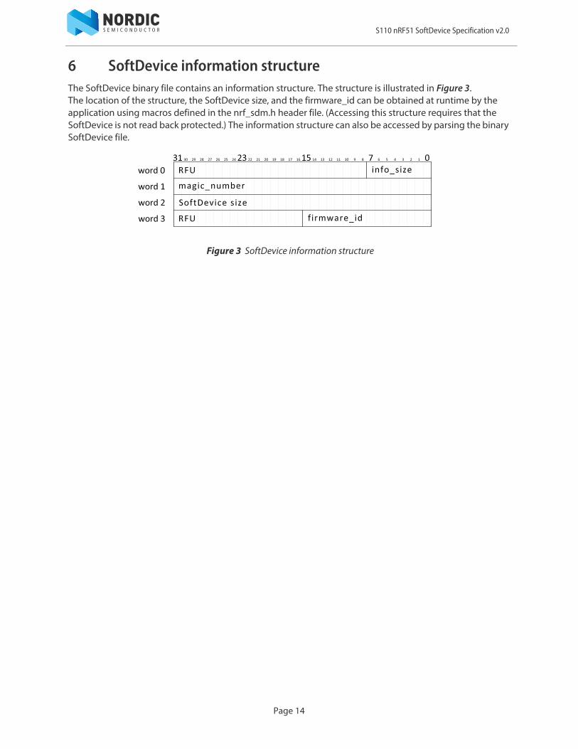
6 SoftDevice information structureThe SoftDevice binary file contains an information structure. The structure is illustrated in Figure 3. The location of the structure, the SoftDevice size, and the firmware_id can be obtained at runtime by the application using macros defined in the nrf_sdm.h header file. (Accessing this structure requires that the SoftDevice is not read back protected.) The information structure can also be accessed by parsing the binary SoftDevice file.
Figure 3 SoftDevice information structure
S110 nRF51 SoftDevice Specification v2.0
Page 15
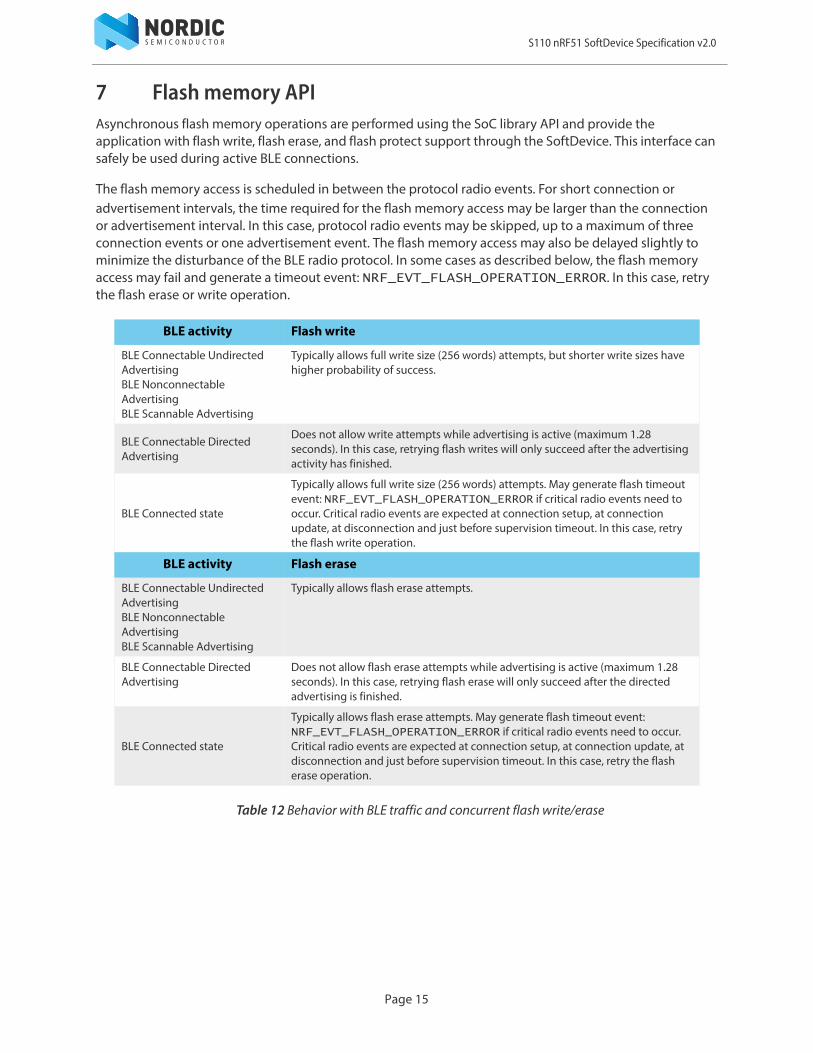
7 Flash memory APIAsynchronous flash memory operations are performed using the SoC library API and provide the application with flash write, flash erase, and flash protect support through the SoftDevice. This interface can safely be used during active BLE connections.
The flash memory access is scheduled in between the protocol radio events. For short connection or advertisement intervals, the time required for the flash memory access may be larger than the connection or advertisement interval. In this case, protocol radio events may be skipped, up to a maximum of three connection events or one advertisement event. The flash memory access may also be delayed slightly to minimize the disturbance of the BLE radio protocol. In some cases as described below, the flash memory access may fail and generate a timeout event: NRF_EVT_FLASH_OPERATION_ERROR. In this case, retry the flash erase or write operation.
Table 12 Behavior with BLE traffic and concurrent flash write/erase
BLE activity Flash write
BLE Connectable Undirected AdvertisingBLE Nonconnectable AdvertisingBLE Scannable Advertising
Typically allows full write size (256 words) attempts, but shorter write sizes have higher probability of success.
BLE Connectable Directed Advertising
Does not allow write attempts while advertising is active (maximum 1.28 seconds). In this case, retrying flash writes will only succeed after the advertising activity has finished.
BLE Connected state
Typically allows full write size (256 words) attempts. May generate flash timeout event: NRF_EVT_FLASH_OPERATION_ERROR if critical radio events need to occur. Critical radio events are expected at connection setup, at connection update, at disconnection and just before supervision timeout. In this case, retry the flash write operation.
BLE activity Flash erase
BLE Connectable Undirected AdvertisingBLE Nonconnectable AdvertisingBLE Scannable Advertising
Typically allows flash erase attempts.
BLE Connectable Directed Advertising
Does not allow flash erase attempts while advertising is active (maximum 1.28 seconds). In this case, retrying flash erase will only succeed after the directed advertising is finished.
BLE Connected state
Typically allows flash erase attempts. May generate flash timeout event: NRF_EVT_FLASH_OPERATION_ERROR if critical radio events need to occur. Critical radio events are expected at connection setup, at connection update, at disconnection and just before supervision timeout. In this case, retry the flash erase operation.

S110 nRF51 SoftDevice Specification v2.0
8 Radio NotificationRadio Notification is a configurable feature that enables ACTIVE and INACTIVE (nACTIVE) signals from the SoftDevice that notify the application when the radio is in use. The signal is sent using software interrupt, as specified in Table 23 on page 37.
In order to make sure that the Radio Notification signals behave in a consistent way, Radio Notification shall always be configured when the SoftDevice is in an idle state with no protocol stack or other SoftDevice activity in progress. It is therefore recommended to configure the Radio Notification signals directly after the SoftDevice has been enabled.
The ACTIVE signal, if enabled, is sent before the Radio Event starts. The nACTIVE signal is sent at the end of the Radio Event. These signals can be used by the application programmer to synchronize application logic with radio activity. For example, the ACTIVE signal can be used to shut off external devices to manage peak current drawn during periods when the radio is on, or to trigger sensor data collection for transmission in the Radio Event.
Because both ACTIVE and nACTIVE use the same software interrupt, it is up to the application to manage them. If both ACTIVE and nACTIVE are configured ON by the application, there will always be an ACTIVE signal before an nACTIVE signal.
Figure 4 shows the active signal in relation to the Radio Event.
Figure 4 BLE Radio Notification
Many packets can be sent and received in one Radio Event. Radio Notification events will be as shown in Figure 5.
Figure 5 BLE Radio Notification, multiple packet transfers
nACTIVEACTIVE
P
tndist
tprep
ACTIVE
TXRX
tevent
TX
RX
ACTIVE
P
tndist
tprep
TX
RX
TX
RX
TX
RX
TX
RX
TX
RX
nACTIVE
tinterval
tevent
tP
Page 16
S110 nRF51 SoftDevice Specification v2.0
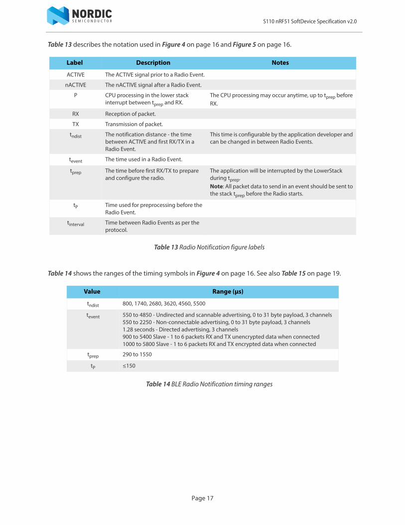
Table 13 describes the notation used in Figure 4 on page 16 and Figure 5 on page 16.
Table 13 Radio Notification figure labels
Table 14 shows the ranges of the timing symbols in Figure 4 on page 16. See also Table 15 on page 19.
Table 14 BLE Radio Notification timing ranges
Label Description Notes
ACTIVE The ACTIVE signal prior to a Radio Event.
nACTIVE The nACTIVE signal after a Radio Event.
P CPU processing in the lower stack interrupt between tprep and RX.
The CPU processing may occur anytime, up to tprep before RX.
RX Reception of packet.
TX Transmission of packet.
tndist The notification distance - the time between ACTIVE and first RX/TX in a Radio Event.
This time is configurable by the application developer and can be changed in between Radio Events.
tevent The time used in a Radio Event.
tprep The time before first RX/TX to prepare and configure the radio.
The application will be interrupted by the LowerStack during tprep.Note: All packet data to send in an event should be sent to the stack tprep before the Radio starts.
tP Time used for preprocessing before the Radio Event.
tinterval Time between Radio Events as per the protocol.
Value Range (μs)
tndist 800, 1740, 2680, 3620, 4560, 5500
tevent 550 to 4850 - Undirected and scannable advertising, 0 to 31 byte payload, 3 channels550 to 2250 - Non-connectable advertising, 0 to 31 byte payload, 3 channels1.28 seconds - Directed advertising, 3 channels900 to 5400 Slave - 1 to 6 packets RX and TX unencrypted data when connected1000 to 5800 Slave - 1 to 6 packets RX and TX encrypted data when connected
tprep 290 to 1550
tP ≤150
Page 17

S110 nRF51 SoftDevice Specification v2.0
Using the numbers from Table 14 on page 17, the amount of CPU time available between ACTIVE and a Radio Event is:
Shown below is the amount of time before stack interrupts begin. Data packets must be transferred to the stack using the API within this time from the ACTIVE signal if they are to be sent in the next Radio Event.
Note: tprep may be greater than tndist when t ndist = 800. If time is required to handle packets or manage peripherals before interrupts are generated by the stack, t ndist should be set greater than 1550.
To ensure the notification signal is available to the application at the configured time when a single link is established, the SoftDevice enforces the following rule (with one exception, see Table 15 on page 19):
tndist tP–
tndist tprep maximum –
tndist tevent tinterval<+
Page 18

S110 nRF51 SoftDevice Specification v2.0
The stack will limit the length of a Radio Event (tevent), thereby reducing the maximum packets exchanged, to accommodate the selected tndist. Figure 6 shows consecutive Radio Events with Radio Notification and illustrates the limitation in tevent which may be required to ensure tndist is preserved.
Figure 6 Consecutive Radio Events with BLE Radio Notification
Table 15 shows the limitation on the maximum number of full length packets which can be transferred per Radio Event given a tndist and tinterval combination.
Table 15 Maximum packet transfer per BLE Radio Event for given combinations of tndist and tinterval.
tndisttinterval
7.5 ms 10 ms ≥ 15 ms
800 5 6 6
1740 4 6 6
2680 4 6 6
3620 3 5 6
4560 2 4 6
5500 01
1. Radio notifications may be suppressed with the longest tndist combined with a 7.5 ms connection interval.
3 6
TX
RX
nACTIVEACTIVE
P
tndist
tprep
tinterval
tevent
TX
RX
nACTIVEACTIVE
P
tndist
tprep tevnt
Page 19

S110 nRF51 SoftDevice Specification v2.0
9 Concurrent Multiprotocol Timeslot APIThe Multiprotocol Timeslot API allows an application developer to safely schedule 2.4 GHz proprietary radio usage while the SoftDevice protocol stack is in use by the device. This allows the nRF51 device to be part of a network using the SoftDevice protocol stack and an alternative network of wireless devices at the same time.
The Timeslot feature gives the application access to the radio and other restricted peripherals, which it does by queueing the application's use of these peripherals with those of the SoftDevice. Using this feature, the application can run other radio protocols (third party custom or proprietary protocols running from application space) concurrently with the internal protocol stack(s) of the SoftDevice. It can also be used to suppress SoftDevice radio activity and reserve guaranteed time for application activities with hard timing requirements which cannot be met by using the SoC Radio Notifications.
The Timeslot feature is part of the SoC library. The feature works by having the SoftDevice time-multiplex access to peripherals between the application and itself. Through the SoC API, the application can open a Timeslot session and request timeslots. When a timeslot is granted, the application has exclusive and real-time access to the normally blocked RADIO, TIMER0, CCM, AAR, and PPI (channels 14 – 15) peripherals and can use these freely for the length of the timeslot, see Table 21 “Hardware access type definitions” on page 35 and Table 22 “Peripheral protection and usage by SoftDevice” on page 36.
9.1 Request typesTimeslots may be requested as earliest possible, in which case the timeslot occurs at the first available opportunity. In the request, the application can limit how far into the future the timeslot may be placed. Timeslots may also be requested at a given time. In this case, the application specifies in the request when the timeslot should start and the time is measured from the start of the previous timeslot. Note that the first request in a session must always be earliest possible to create the timing reference point for later timeslots. The application may also request to extend an on-going timeslot. Extension requests may be repeated, prolonging the timeslot even further.
Timeslots requested as earliest possible are useful for single timeslots and for non-periodic or non-timed activity. Timeslots requested at a given time relative to the previous timeslot are useful for periodic and timed activities; for example, a periodic proprietary radio protocol. Timeslot extension may be used to secure as much continuous radio time as possible for the application; for example, running an “always on” radio listener.
9.2 Request prioritiesTimeslots can be requested at either high or normal priority, indicating how important it is for the application to access the specified peripherals. Using normal priority should be considered best practice to minimize the influence of the use of the Multiprotocol Timeslot API on other activities. The high priority should only be used when required, such as for running a radio protocol with certain timing requirements that are not met using normal priority.
Page 20

S110 nRF51 SoftDevice Specification v2.0
9.3 Timeslot lengthThe length of the timeslot is specified by the application in the request and ranges from 100 μs to 100 ms. Longer continuous timeslots can be achieved by requesting to extend the current timeslot. Successive extensions will give a timeslot as long as possible within the limits set by other SoftDevice activities, up to a maximum of 128 s.
9.4 SchedulingTimeslots requested by the application are scheduled within the SoftDevice along with the SoftDevice protocol and the Flash API activities.
Whether the timeslot request is granted and access to the peripherals given is based on when the request was made, when the timeslot is wanted, the priority of the request, and the requested length of the timeslot. If the requested timeslot does not collide with other activities, the request will be granted and the timeslot scheduled. If the requested timeslot collides with an already scheduled activity with equal or higher priority, the request will be blocked. If a later arriving activity of higher priority causes a collision, the request will be canceled and the scheduled timeslot revoked. However, a timeslot that has already started cannot be interrupted or canceled. Timeslots requested at high priority will cancel other activities scheduled at lower priorities in case of a collision. Also, requests for short timeslots have a higher probability of succeeding than requests for longer timeslots because shorter timeslots are easier to fit into the schedule.
Note: Radio Notification signals behave the same way for timeslots requested through the Multiprotocol Timeslot interface as for SoftDevice internal activities, see Chapter 8 “Radio Notification” on page 16 for more information. If Radio Notifications are enabled, Multiprotocol Timeslots will be notified.
9.5 Performance considerationsSince the Multiprotocol Timeslot API shares core peripherals with the SoftDevice, and are scheduled along with other SoftDevice activities, use of the Timeslot feature may influence SoftDevice performance. Therefore the application configuration of the SoftDevice protocol should be considered when using the Multiprotocol Timeslot API.
In general, all timeslot requests should use the lowest priority to ensure that interruptions to other activity is minimized. In addition, timeslots should be kept as short as possible in order to minimize the impact on the overall performance of the device. Similarly, requesting a shorter timeslot and then extending it gives more flexibility to schedule other activities than requesting a longer timeslot.
Page 21
S110 nRF51 SoftDevice Specification v2.0
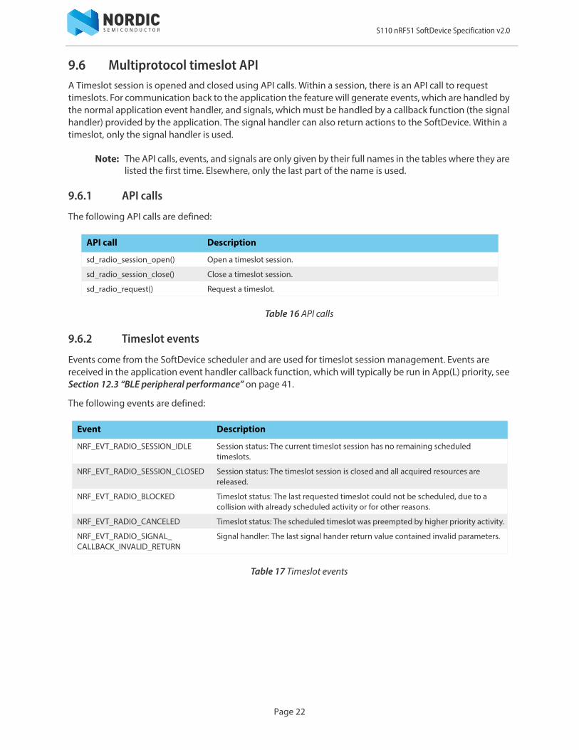
9.6 Multiprotocol timeslot APIA Timeslot session is opened and closed using API calls. Within a session, there is an API call to request timeslots. For communication back to the application the feature will generate events, which are handled by the normal application event handler, and signals, which must be handled by a callback function (the signal handler) provided by the application. The signal handler can also return actions to the SoftDevice. Within a timeslot, only the signal handler is used.
Note: The API calls, events, and signals are only given by their full names in the tables where they are listed the first time. Elsewhere, only the last part of the name is used.
9.6.1 API calls
The following API calls are defined:
Table 16 API calls
9.6.2 Timeslot events
Events come from the SoftDevice scheduler and are used for timeslot session management. Events are received in the application event handler callback function, which will typically be run in App(L) priority, see Section 12.3 “BLE peripheral performance” on page 41.
The following events are defined:
Table 17 Timeslot events
API call Description
sd_radio_session_open() Open a timeslot session.
sd_radio_session_close() Close a timeslot session.
sd_radio_request() Request a timeslot.
Event Description
NRF_EVT_RADIO_SESSION_IDLE Session status: The current timeslot session has no remaining scheduled timeslots.
NRF_EVT_RADIO_SESSION_CLOSED Session status: The timeslot session is closed and all acquired resources are released.
NRF_EVT_RADIO_BLOCKED Timeslot status: The last requested timeslot could not be scheduled, due to a collision with already scheduled activity or for other reasons.
NRF_EVT_RADIO_CANCELED Timeslot status: The scheduled timeslot was preempted by higher priority activity.
NRF_EVT_RADIO_SIGNAL_CALLBACK_INVALID_RETURN
Signal handler: The last signal hander return value contained invalid parameters.
Page 22

S110 nRF51 SoftDevice Specification v2.0
9.6.3 Timeslot signals
Signals come from the peripherals and arrive within a timeslot. Signals are received in a signal handler callback function that the application must provide. The signal handler runs in LowerStack priority, which is the highest priority in the system, see Section 12.3 “BLE peripheral performance” on page 41.
Table 18 Timeslot signals
9.6.4 Signal handler return actions
The return value from the application signal handler to the SoftDevice contains an action. The signal handler action return values are:
Table 19 Signal handler action return values
9.6.5 Ending a timeslot in time
The application is responsible for keeping track of timing within the timeslot and ensuring that the application’s use of the peripherals does not last for longer than the granted timeslot. For these purposes, the application is granted access to the TIMER0 peripheral for the length of the timeslot. This timer is started from zero by the SoftDevice at the start of the timeslot, and is configured to run at 1 MHz. The recommended practice is to set up a timer interrupt that expires before the timeslot expires, with enough time left of the timeslot to do any clean-up actions before the timeslot ends. Such a timer interrupt can also be used to request an extension of the timeslot, but there must still be enough time to clean up if the extension is not granted.
Signal Description
NRF_RADIO_CALLBACK_SIGNAL_TYPE_START
Start of the timeslot. The application now has exclusive access to the peripherals for the full length of the timeslot.
NRF_RADIO_CALLBACK_SIGNAL_TYPE_RADIO
Radio interrupt, for more information, see chapter 2.4 GHz radio (RADIO) in the nRF51 Reference Manual.
NRF_RADIO_CALLBACK_SIGNAL_TYPE_TIMER0
Timer interrupt, for more information, see chapter Timer/counter (TIMER) in the nRF51 Reference Manual.
NRF_RADIO_CALLBACK_SIGNAL_TYPE_EXTEND_SUCCEEDED
The latest extend action succeeded.
NRF_RADIO_CALLBACK_SIGNAL_TYPE_EXTEND_FAILED
The latest extend action failed.
Return value Description
NRF_RADIO_SIGNAL_CALLBACK_ACTION_NONE
The timeslot processing is not complete. The SoftDevice will take no action.
NRF_RADIO_SIGNAL_CALLBACK_ACTION_END
The current timeslot has ended. The SoftDevice can now resume other activities.
NRF_RADIO_SIGNAL_CALLBACK_ACTION_REQUEST_AND_END
The current timeslot has ended. The SoftDevice is requested to schedule a new timeslot, after which it can resume other activities.
NRF_RADIO_SIGNAL_CALLBACK_ACTION_EXTEND
The SoftDevice is requested to extend the ongoing timeslot.
Page 23
S110 nRF51 SoftDevice Specification v2.0
9.6.6 The signal handler runs at LowerStack priority
The signal handler runs at LowerStack priority, which is the highest priority. Therefore, it cannot be interrupted by any other activity. Also, as for the App(H) interrupt, SVC calls are not available in the signal handler. It is a requirement that processing in the signal handler does not exceed the granted time of the timeslot. If it does, the behavior of the SoftDevice is undefined and the SoftDevice may malfunction.
The signal handler may be called several times during a timeslot. It is recommended to use the signal handler only for the real time signal handling. When a signal has been handled, exit the signal handler to wait for the next signal. Processing other than signal handling should be run at lower priorities, outside of the signal handler.
Page 24
S110 nRF51 SoftDevice Specification v2.0
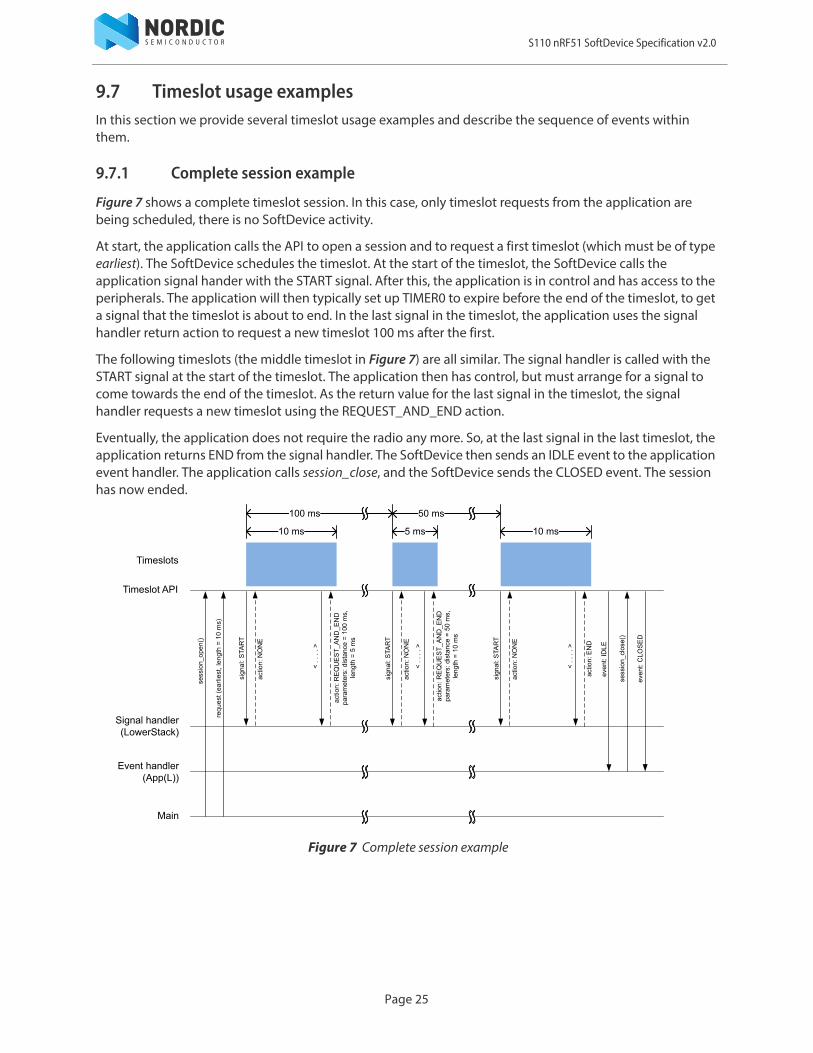
9.7 Timeslot usage examplesIn this section we provide several timeslot usage examples and describe the sequence of events within them.
9.7.1 Complete session example
Figure 7 shows a complete timeslot session. In this case, only timeslot requests from the application are being scheduled, there is no SoftDevice activity.
At start, the application calls the API to open a session and to request a first timeslot (which must be of type earliest). The SoftDevice schedules the timeslot. At the start of the timeslot, the SoftDevice calls the application signal hander with the START signal. After this, the application is in control and has access to the peripherals. The application will then typically set up TIMER0 to expire before the end of the timeslot, to get a signal that the timeslot is about to end. In the last signal in the timeslot, the application uses the signal handler return action to request a new timeslot 100 ms after the first.
The following timeslots (the middle timeslot in Figure 7) are all similar. The signal handler is called with the START signal at the start of the timeslot. The application then has control, but must arrange for a signal to come towards the end of the timeslot. As the return value for the last signal in the timeslot, the signal handler requests a new timeslot using the REQUEST_AND_END action.
Eventually, the application does not require the radio any more. So, at the last signal in the last timeslot, the application returns END from the signal handler. The SoftDevice then sends an IDLE event to the application event handler. The application calls session_close, and the SoftDevice sends the CLOSED event. The session has now ended.
Figure 7 Complete session example
Page 25
S110 nRF51 SoftDevice Specification v2.0
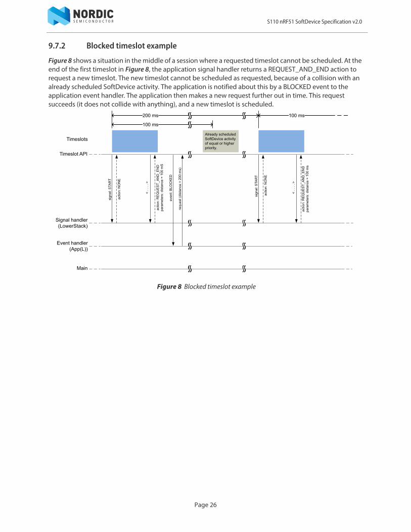
9.7.2 Blocked timeslot example
Figure 8 shows a situation in the middle of a session where a requested timeslot cannot be scheduled. At the end of the first timeslot in Figure 8, the application signal handler returns a REQUEST_AND_END action to request a new timeslot. The new timeslot cannot be scheduled as requested, because of a collision with an already scheduled SoftDevice activity. The application is notified about this by a BLOCKED event to the application event handler. The application then makes a new request further out in time. This request succeeds (it does not collide with anything), and a new timeslot is scheduled.
Figure 8 Blocked timeslot example
Page 26
S110 nRF51 SoftDevice Specification v2.0
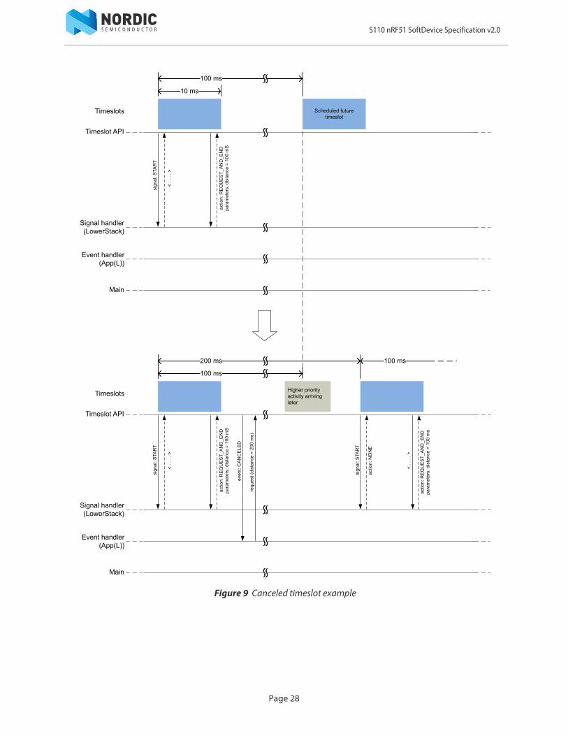
9.7.3 Canceled timeslot example
Figure 9 on page 28 shows a situation in the middle of a session where a requested and scheduled application timeslot is being revoked. The upper part of Figure 9 on page 28 shows that the application has ended a timeslot by returning the REQUEST_AND_END action, and the new timeslot has been scheduled. The new scheduled timeslot has not been started yet, it is still some time into the future. The lower part of Figure 9 on page 28 shows the situation some time later. In the meantime, time for a SoftDevice activity of higher priority has been requested internally in the SoftDevice, at a time which collides with the scheduled application timeslot. To accommodate the higher priority request, the application timeslot has been removed from the schedule, and the higher priority SoftDevice activity scheduled instead. The application is notified about this by a CANCELED event to the application event handler. The application then makes a new request further out in time. This request succeeds (it does not collide with anything), and a new timeslot is scheduled.
Page 27
S110 nRF51 SoftDevice Specification v2.0
Figure 9 Canceled timeslot example
Page 28
S110 nRF51 SoftDevice Specification v2.0
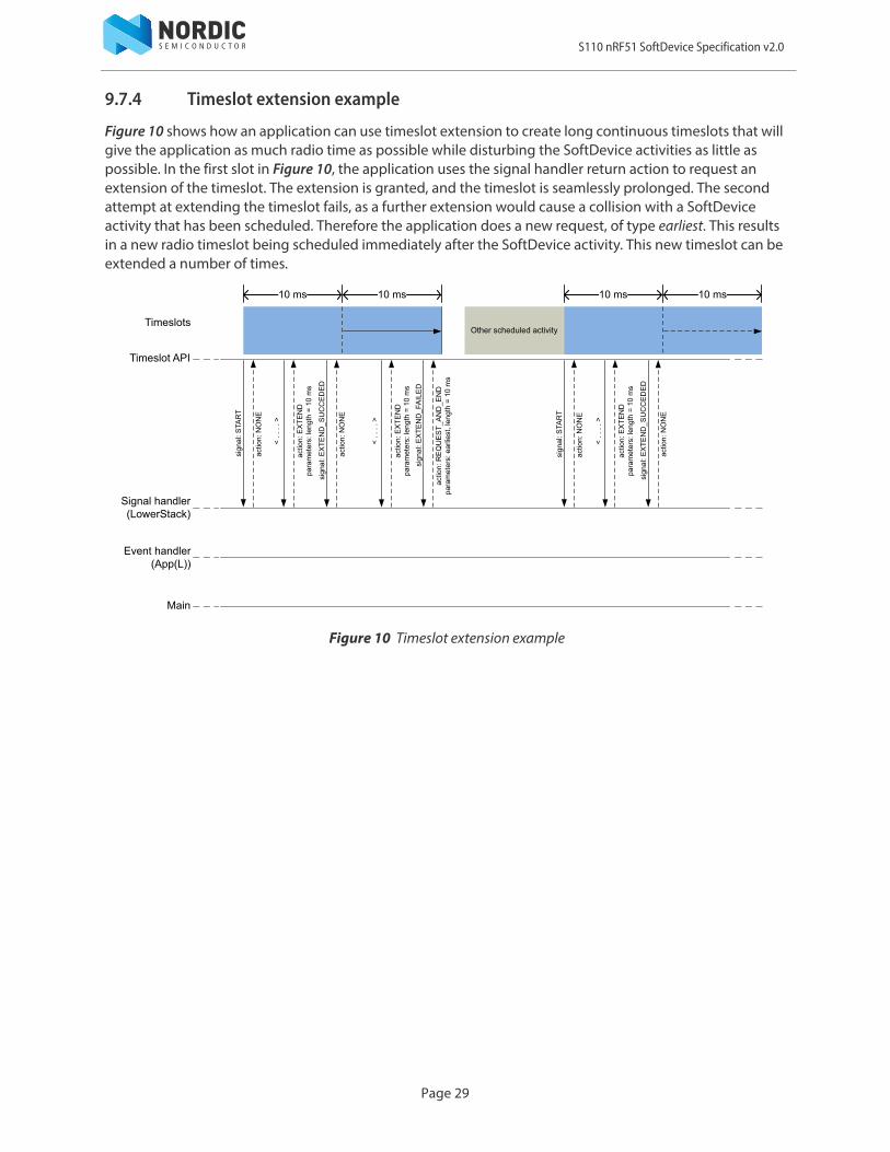
9.7.4 Timeslot extension example
Figure 10 shows how an application can use timeslot extension to create long continuous timeslots that will give the application as much radio time as possible while disturbing the SoftDevice activities as little as possible. In the first slot in Figure 10, the application uses the signal handler return action to request an extension of the timeslot. The extension is granted, and the timeslot is seamlessly prolonged. The second attempt at extending the timeslot fails, as a further extension would cause a collision with a SoftDevice activity that has been scheduled. Therefore the application does a new request, of type earliest. This results in a new radio timeslot being scheduled immediately after the SoftDevice activity. This new timeslot can be extended a number of times.
Figure 10 Timeslot extension example
Page 29

S110 nRF51 SoftDevice Specification v2.0
10 Master Boot Record and BootloaderThe SoftDevice supports the use of a bootloader. A bootloader may be used to update the firmware on the chip. The SoftDevice also contains a Master Boot Record (MBR). The MBR is necessary in order for the bootloader to update the SoftDevice, or to update the bootloader itself. The MBR is a required component in the system. The inclusion of a bootloader is optional.
10.1 Master Boot RecordThe Master Boot Record (MBR) module occupies a defined region in flash memory where the System Vector table resides. All exceptions (reset, hard fault, interrupts, SVC) are processed first by the MBR and then forwarded to appropriate handlers (for example bootloader or SoftDevice). The main feature of the MBR is to provide an interface to allow in-system updates of the SoftDevice and bootloader firmware. The MBR is not updated between versions of the SoftDevice, meaning that during an update process, the MBR is never erased. The MBR ensures safe restart of any ongoing update process if an unexpected reset occurs.
10.2 BootloaderA bootloader may be used to handle in-system update procedures. The bootloader has access to the full SoftDevice API and can be implemented just as any application that uses a SoftDevice. In particular, the bootloader can make use of the SoftDevice API to enable protocol stack interaction.
The bootloader is supported in the SoftDevice architecture by using a configurable base address for the bootloader in application code space. The base address is configured by setting the UICR.BOOTLOADERADDR register. The bootloader is responsible for determining the start address of the application. It uses sd_softdevice_vector_table_base_set(uint32_t address) to tell the SoftDevice where the application starts. The bootloader is also responsible for keeping track of, and verifying the SoftDevice. If an unexpected reset occurs during an update of the SoftDevice, it is the responsibility of the bootloader to detect this and recover.
Page 30
S110 nRF51 SoftDevice Specification v2.0
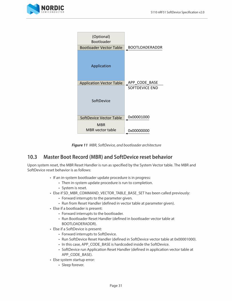
Figure 11 MBR, SoftDevice, and bootloader architecture
10.3 Master Boot Record (MBR) and SoftDevice reset behaviorUpon system reset, the MBR Reset Handler is run as specified by the System Vector table. The MBR and SoftDevice reset behavior is as follows:
• If an in-system bootloader update procedure is in progress:• Then in-system update procedure is run to completion.• System is reset.
• Else if SD_MBR_COMMAND_VECTOR_TABLE_BASE_SET has been called previously:• Forward interrupts to the parameter given.• Run from Reset Handler (defined in vector table at parameter given).
• Else if a bootloader is present:• Forward interrupts to the bootloader.• Run Bootloader Reset Handler (defined in bootloader vector table at
BOOTLOADERADDR).• Else if a SoftDevice is present:
• Forward interrupts to SoftDevice.• Run SoftDevice Reset Handler (defined in SoftDevice vector table at 0x00001000).• In this case, APP_CODE_BASE is hardcoded inside the SoftDevice.• SoftDevice run Application Reset Handler (defined in application vector table at
APP_CODE_BASE).• Else system startup error:
• Sleep forever.
SoftDevice
Application
Application Vector Table
SoftDevice Vector Table
APP_CODE_BASE
BOOTLOADERADDRBootloader Vector Table
(Optional)Bootloader
0x00001000
MBRMBR vector table 0x00000000
SoftDevice Vector Table
SOFTDEVICE END
Page 31

S110 nRF51 SoftDevice Specification v2.0
10.4 Master Boot Record (MBR) and SoftDevice initializationThe SoftDevice can be enabled by the bootloader by performing the following in this order:
1. Issue command for MBR to forward interrupts to the SoftDevice using sd_mbr_command() with SD_MBR_COMMAND_INIT_SD.
2. Issue command for the SoftDevice to forward interrupts to the bootloader using sd_softdevice_vector_table_base_set(uint32_t address) with BOOTLOADERADDR as parameter.
3. Enable SoftDevice using sd_softdevice_enable().
For a bootloader to transfer execution from itself to the application, the following can be performed:
1. If interrupts have not been forwarded to SoftDevice, issue command for MBR to forward interrupts to SoftDevice using sd_mbr_command() with SD_MBR_COMMAND_INIT_SD.
2. Ensure SoftDevice is disabled using sd_softdevice_disable().3. Issue command for the SoftDevice to forward interrupts to the application using
sd_softdevice_vector_table_base_set(uint32_t address) with APP_CODE_BASE as parameter.4. Branch to application's reset handler after reading the handler from the Application Vector Table.
Page 32
S110 nRF51 SoftDevice Specification v2.0
11 SoC resource requirementsThe SoftDevice and MBR are designed to be installed on a System on Chip (SoC) in the lower part of the code memory space. After a reset, the MBR will use some RAM to store state information. When the SoftDevice is enabled, it uses resources on the chip including RAM and hardware peripherals like the radio. This chapter describes how the MBR and SoftDevice uses resources. The SoftDevice requirements are shown both when enabled and disabled.
11.1 Attribute Table sizeThe size of the Attribute Table can be configured through the SoftDevice API when initializing the Bluetooth low energy stack. The amount of RAM reserved by the SoftDevice, and thereby the amount of RAM available for the application, is dependent upon this configuration.
The Attribute Table size (ATTR_TAB_SIZE) has a default value of 0x700 bytes. This value has been chosen for compatibility with previous SoftDevice versions where the Attribute Table size was not configurable, and using this default value will result in the same SoftDevice RAM requirements as for those previous versions.
Applications that require an Attribute Table smaller or bigger than the default one can choose to either reduce or increase the Attribute table size. The amount of RAM reserved by the SoftDevice, and the start address for the application RAM (APP_RAM_BASE) will then change accordingly. The application linker configuration must be adapted to reflect the changed SoftDevice RAM requirement.
Refer to the SoftDevice API for more information on how to configure the Attribute Table size.
Page 33
S110 nRF51 SoftDevice Specification v2.0
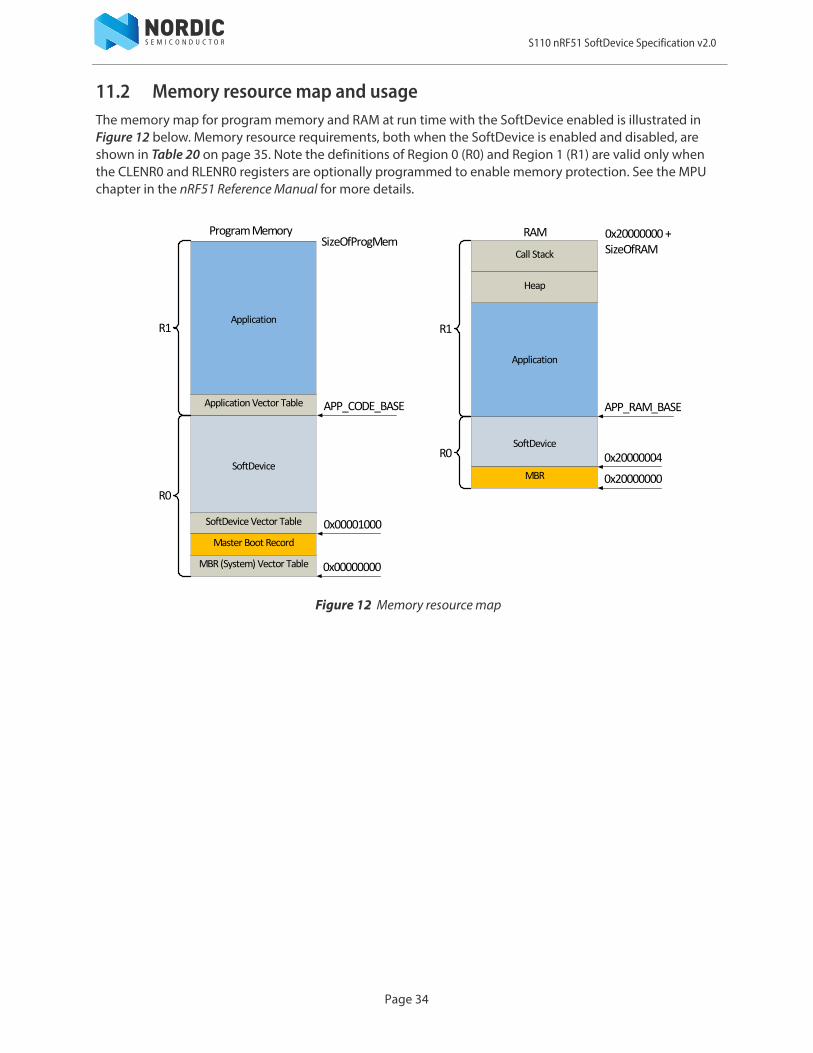
11.2 Memory resource map and usageThe memory map for program memory and RAM at run time with the SoftDevice enabled is illustrated in Figure 12 below. Memory resource requirements, both when the SoftDevice is enabled and disabled, are shown in Table 20 on page 35. Note the definitions of Region 0 (R0) and Region 1 (R1) are valid only when the CLENR0 and RLENR0 registers are optionally programmed to enable memory protection. See the MPU chapter in the nRF51 Reference Manual for more details.
Figure 12 Memory resource map
SoftDevice
Application
SizeOfProgMem
Application Vector Table
SoftDevice Vector Table
RAMProgram Memory
SoftDevice
Application
0x20000000 + SizeOfRAMCall Stack
Heap
R1
R0
Master Boot Record
MBR (System) Vector Table 0x00000000
0x00001000
APP_CODE_BASE
MBR 0x20000000
0x20000004
APP_RAM_BASE
R1
R0
Page 34
S110 nRF51 SoftDevice Specification v2.0
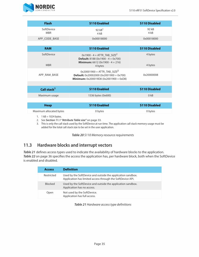
Table 20 S110 Memory resource requirements
11.3 Hardware blocks and interrupt vectorsTable 21 defines access types used to indicate the availability of hardware blocks to the application. Table 22 on page 36 specifies the access the application has, per hardware block, both when the SoftDevice is enabled and disabled.
Table 21 Hardware access type definitions
Flash S110 Enabled S110 Disabled
SoftDeviceMBR
92 kB1
4 kB92 kB4 kB
APP_CODE_BASE 0x00018000 0x00018000
RAM S110 Enabled S110 Disabled
SoftDevice
MBR
0x1900 - 4 + ATTR_TAB_SIZE2
Default: 8188 (0x1900 - 4 + 0x700)Minimum: 6612 (0x1900 - 4 + 216)
4 bytes
4 bytes
4 bytes
APP_RAM_BASE0x20001900 + ATTR_TAB_SIZE2
Default: 0x20002000 (0x2001900 + 0x700)Minimum: 0x200019D8 (0x2001900 + 0xD8)
0x20000008
Call stack3 S110 Enabled S110 Disabled
Maximum usage 1536 bytes (0x600) 0 kB
Heap S110 Enabled S110 Disabled
Maximum allocated bytes 0 bytes 0 bytes
1. 1 kB = 1024 bytes.2. See Section 11.1 “Attribute Table size” on page 33.3. This is only the call stack used by the SoftDevice at run time. The application call stack memory usage must be
added for the total call stack size to be set in the user application.
Access Definition
Restricted Used by the SoftDevice and outside the application sandbox.Application has limited access through the SoftDevice API.
Blocked Used by the SoftDevice and outside the application sandbox.Application has no access.
Open Not used by the SoftDevice. Application has full access.
Page 35
S110 nRF51 SoftDevice Specification v2.0
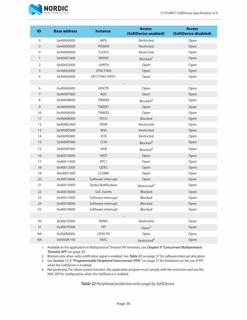
Table 22 Peripheral protection and usage by SoftDevice
ID Base address Instance Access (SoftDevice enabled)
Access (SoftDevice disabled)
0 0x40000000 MPU Restricted Open
0 0x40000000 POWER Restricted Open
0 0x40000000 CLOCK Restricted Open
1 0x40001000 RADIO Blocked1 Open
2 0x40002000 UART0 Open Open
3 0x40003000 SPI0/TWI0 Open Open
4 0x40004000 SPI1/TWI1/SPIS1 Open Open
...
6 0x40006000 GPIOTE Open Open
7 0x40007000 ADC Open Open
8 0x40008000 TIMER0 Blocked1 Open
9 0x40009000 TIMER1 Open Open
10 0x4000A000 TIMER2 Open Open
11 0x4000B000 RTC0 Blocked Open
12 0x4000C000 TEMP Restricted Open
13 0x4000D000 RNG Restricted Open
14 0x4000E000 ECB Restricted Open
15 0x4000F000 CCM Blocked1 Open
15 0x4000F000 AAR Blocked1 Open
16 0x40010000 WDT Open Open
17 0x40011000 RTC1 Open Open
18 0x40012000 QDEC Open Open
19 00x4001300 LCOMP Open Open
20 0x40014000 Software interrupt Open Open
21 0x40015000 Radio Notification Restricted2 Open
22 0x40016000 SoC Events Blocked Open
23 0x40017000 Software interrupt Blocked Open
24 0x40018000 Software interrupt Blocked Open
25 0x40019000 Software interrupt Blocked Open
...
30 0x4001E000 NVMC Restricted Open
31 0x4001F000 PPI Open3 Open
NA 0x50000000 GPIO P0 Open Open
NA 0xE000E100 NVIC Restricted4 Open
1. Available to the application in Multiprotocol Timeslot API timeslots, see Chapter 9 “Concurrent Multiprotocol Timeslot API” on page 20.
2. Blocked only when radio notification signal is enabled. See Table 23 on page 37 for software interrupt allocation.3. See Section 11.5 “Programmable Peripheral Interconnect (PPI)” on page 37 for limitations on the use of PPI
when the SoftDevice is enabled.4. Not protected. For robust system function, the application program must comply with the restriction and use the
NVIC API for configuration when the SoftDevice is enabled.
Page 36

S110 nRF51 SoftDevice Specification v2.0
11.4 Application signals - software interruptsSoftware interrupts are used by the SoftDevice to signal a change in events. Table 23 shows the allocation of software interrupt vectors to SoftDevice signals.
Table 23 Software interrupt allocation
11.5 Programmable Peripheral Interconnect (PPI)PPI may be configured using the PPI API in the SoC library. This API is available both when the SoftDevice is disabled and when it is enabled. It is also possible to configure the PPI using the CMSIS directly.
When the SoftDevice is disabled, all PPI channels and groups are available to the application. When the SoftDevice is enabled, some PPI channels and groups are in use by the SoftDevice. See Table 24.
When the SoftDevice is enabled, the application program must not change the configuration of PPI channels or groups used by the SoftDevice. Failing to comply with this will cause the SoftDevice to not operate properly.
Table 24 PPI channel and group availability
Software interrupt (SWI) Peripheral ID SoftDevice Signal
0 20 Unused by the SoftDevice and available to the application.
1 21 Radio Notification - optionally configured through API.
2 22 SoftDevice Event Notification.
3 23 Reserved.
4 24 LowerStack processing - not user configurable.
5 25 UpperStack signaling - not user configurable.
PPI channel allocation SoftDevice enabled SoftDevice disabled
Application Channels 0 - 13 Channels 0 - 15
SoftDevice Channels 14 - 151
1. Available to the application in Multiprotocol Timeslot API timeslots, see Chapter 9 “Concurrent Multiprotocol Timeslot API” on page 20.
-
Preprogrammed channels SoftDevice enabled SoftDevice disabled
Application - Channels 20 - 31
SoftDevice Channels 20 - 31 -
PPI group allocation SoftDevice enabled SoftDevice disabled
Application Groups 0 - 1 Groups 0 - 3
SoftDevice Groups 2 - 3 -
Page 37
S110 nRF51 SoftDevice Specification v2.0
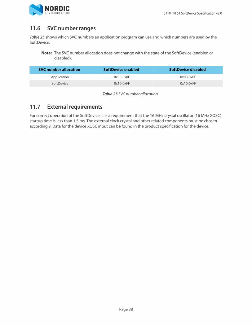
11.6 SVC number rangesTable 25 shows which SVC numbers an application program can use and which numbers are used by the SoftDevice.
Note: The SVC number allocation does not change with the state of the SoftDevice (enabled or disabled).
Table 25 SVC number allocation
11.7 External requirementsFor correct operation of the SoftDevice, it is a requirement that the 16 MHz crystal oscillator (16 MHz XOSC) startup time is less than 1.5 ms. The external clock crystal and other related components must be chosen accordingly. Data for the device XOSC input can be found in the product specification for the device.
SVC number allocation SoftDevice enabled SoftDevice disabled
Application 0x00-0x0F 0x00-0x0F
SoftDevice 0x10-0xFF 0x10-0xFF
Page 38

S110 nRF51 SoftDevice Specification v2.0
12 Processor availability and interrupt latencyThis chapter documents key SoftDevice performance parameters for processor availability and interrupt latency.
12.1 Interrupt latency due to SoC framework
Latency, additional to ARM® Cortex™-M0 hardware architecture latency, is introduced by SoftDevice logic to manage interrupt events. This latency occurs when an interrupt is forwarded to the application from the SoftDevice and is part of the minimum latency for each application interrupt. Additional latency is incurred due to interrupt processing and forwarding performed by the Master Boot Record (MBR). The maximum application interrupt latency is dependent on protocol stack activity as described in Section 12.2 “Processor availability” on page 40.
Table 26 Additional latency due to SoftDevice and MBR processing
See Table 22 on page 36 for open, blocked, and restricted peripherals.
Interrupt CPU cycles Latency at 16 MHz
Open peripheral interrupt 49 3.1 μs
Blocked or restricted peripheral interrupt(only forwarded when SoftDevice disabled)
67 4.2 μs
Application SVC interrupt 43 2.7 μs
Page 39
S110 nRF51 SoftDevice Specification v2.0
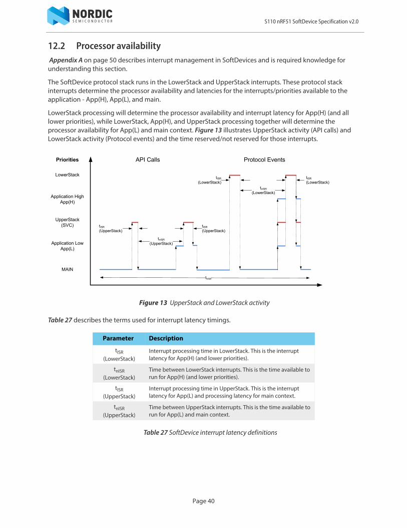
12.2 Processor availability Appendix A on page 50 describes interrupt management in SoftDevices and is required knowledge for understanding this section.
The SoftDevice protocol stack runs in the LowerStack and UpperStack interrupts. These protocol stack interrupts determine the processor availability and latencies for the interrupts/priorities available to the application - App(H), App(L), and main.
LowerStack processing will determine the processor availability and interrupt latency for App(H) (and all lower priorities), while LowerStack, App(H), and UpperStack processing together will determine the processor availability for App(L) and main context. Figure 13 illustrates UpperStack activity (API calls) and LowerStack activity (Protocol events) and the time reserved/not reserved for those interrupts.
Figure 13 UpperStack and LowerStack activity
Table 27 describes the terms used for interrupt latency timings.
Table 27 SoftDevice interrupt latency definitions
Parameter Description
tISR(LowerStack)
Interrupt processing time in LowerStack. This is the interrupt latency for App(H) (and lower priorities).
tnISR(LowerStack)
Time between LowerStack interrupts. This is the time available to run for App(H) (and lower priorities).
tISR(UpperStack)
Interrupt processing time in UpperStack. This is the interrupt latency for App(L) and processing latency for main context.
tnISR(UpperStack)
Time between UpperStack interrupts. This is the time available to run for App(L) and main context.
Priorities Protocol EventsAPI Calls
tnISR
(UpperStack)
tISR
(UpperStack)
tnISR
(LowerStack)
tISR
(LowerStack)tISR
(LowerStack)
tISR
(UpperStack)
ttotal
LowerStack
Application High App(H)
UpperStack(SVC)
Application LowApp(L)
MAIN
Page 40
S110 nRF51 SoftDevice Specification v2.0
12.3 BLE peripheral performanceThis section describes the processor availability and interrupt latency for the BLE peripheral stack.
The interrupt latency and processor availability interrupt latencies are dependent upon whether the
SoftDevice uses CPU suspend1 during radio activity or not. For S110 SoftDevices 7.0 and earlier, CPU suspend was always used. For version 7.1, CPU Suspend was enabled by default, but could be turned off. For current S110 SoftDevice versions (S110 8.x), CPU suspend is by default not enabled, but may optionally be enabled for compatibility with older versions of nRF51 chips. See your S110 SoftDevice release documentation for details. This document describes interrupt latency and CPU availability when CPU Suspend is not used.
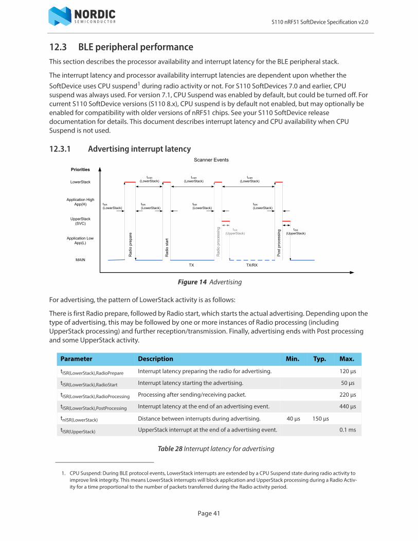
12.3.1 Advertising interrupt latency
Figure 14 Advertising
For advertising, the pattern of LowerStack activity is as follows:
There is first Radio prepare, followed by Radio start, which starts the actual advertising. Depending upon the type of advertising, this may be followed by one or more instances of Radio processing (including UpperStack processing) and further reception/transmission. Finally, advertising ends with Post processing and some UpperStack activity.
Table 28 Interrupt latency for advertising
1. CPU Suspend: During BLE protocol events, LowerStack interrupts are extended by a CPU Suspend state during radio activity to improve link integrity. This means LowerStack interrupts will block application and UpperStack processing during a Radio Activ-ity for a time proportional to the number of packets transferred during the Radio activity period.
Parameter Description Min. Typ. Max.
tISR(LowerStack),RadioPrepare Interrupt latency preparing the radio for advertising. 120 μs
tISR(LowerStack),RadioStart Interrupt latency starting the advertising. 50 μs
tISR(LowerStack),RadioProcessing Processing after sending/receiving packet. 220 μs
tISR(LowerStack),PostProcessing Interrupt latency at the end of an advertising event. 440 μs
tnISR(LowerStack) Distance between interrupts during advertising. 40 μs 150 μs
tISR(UpperStack) UpperStack interrupt at the end of a advertising event. 0.1 ms
Page 41
S110 nRF51 SoftDevice Specification v2.0
12.3.2 BLE peripheral connection
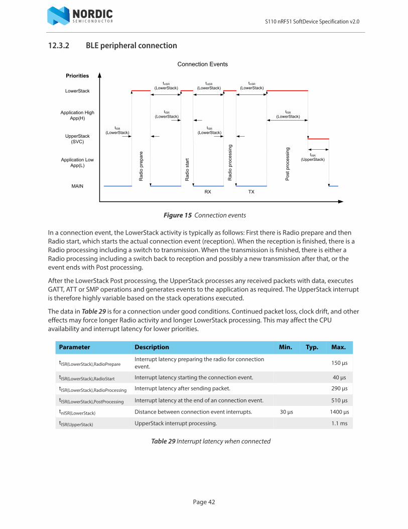
Figure 15 Connection events
In a connection event, the LowerStack activity is typically as follows: First there is Radio prepare and then Radio start, which starts the actual connection event (reception). When the reception is finished, there is a Radio processing including a switch to transmission. When the transmission is finished, there is either a Radio processing including a switch back to reception and possibly a new transmission after that, or the event ends with Post processing.
After the LowerStack Post processing, the UpperStack processes any received packets with data, executes GATT, ATT or SMP operations and generates events to the application as required. The UpperStack interrupt is therefore highly variable based on the stack operations executed.
The data in Table 29 is for a connection under good conditions. Continued packet loss, clock drift, and other effects may force longer Radio activity and longer LowerStack processing. This may affect the CPU availability and interrupt latency for lower priorities.
Table 29 Interrupt latency when connected
Parameter Description Min. Typ. Max.
tISR(LowerStack),RadioPrepareInterrupt latency preparing the radio for connection event.
150 μs
tISR(LowerStack),RadioStart Interrupt latency starting the connection event. 40 μs
tISR(LowerStack),RadioProcessing Interrupt latency after sending packet. 290 μs
tISR(LowerStack),PostProcessing Interrupt latency at the end of an connection event. 510 μs
tnISR(LowerStack) Distance between connection event interrupts. 30 μs 1400 μs
tISR(UpperStack) UpperStack interrupt processing. 1.1 ms
Page 42

S110 nRF51 SoftDevice Specification v2.0
12.3.3 API calls
The following table describes the timing for API call handling in the UpperStack.
Table 30 SoftDevice interrupt latency - UpperStack
12.3.4 CPU utilization in connection
Table 31 shows the CPU capacity available for an application with given a set of typical stack connection parameters.
Table 31 CPU capacity available for the application, for some connection configurationss
12.4 Performance with Flash memory API and Concurrent Multiprotocol Timeslot APIThe LowerStack interrupt is also used by the Flash memory API processing and by the Concurrent Multiprotocol Timeslot API processing. Therefore use of these APIs may affect CPU availability and interrupt latencies for all lower priorities. The effects of this are dependent upon the application and the use case.
Parameter DescriptionUpperStack
Min Nom Max
tISR(upper stack) Maximum interrupt processing time - - 250 μs
tnISR(upper stack) Minimum time between interrupts Application dependent.1
1. Calls to the SoftDevice API trigger the upper stack interrupt.
BLE connection configuration % CPU capacity available
Connection interval 100 msNo data transfer
~99%
Connection interval 100 ms1 packet transfer per event (bidirectional)
~97%
Connection interval 7.5 ms4 packet transfer per event
15%
Page 43
S110 nRF51 SoftDevice Specification v2.0
Page 44
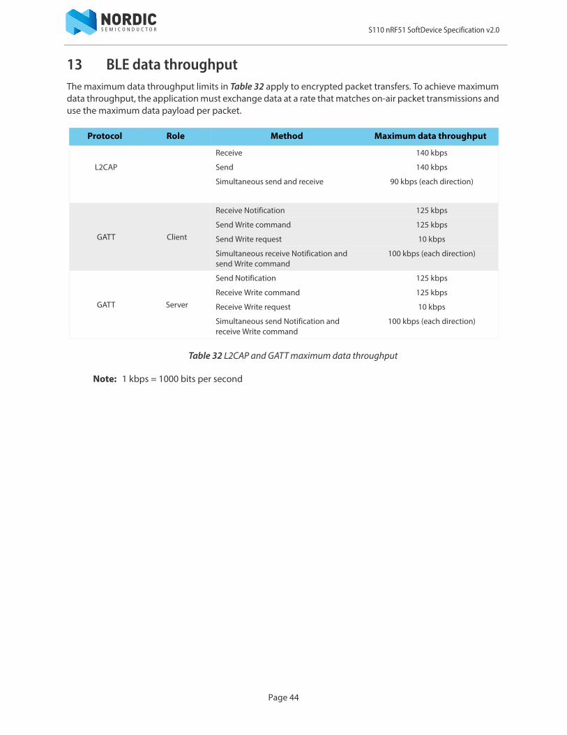
13 BLE data throughputThe maximum data throughput limits in Table 32 apply to encrypted packet transfers. To achieve maximum data throughput, the application must exchange data at a rate that matches on-air packet transmissions and use the maximum data payload per packet.
Table 32 L2CAP and GATT maximum data throughput
Note: 1 kbps = 1000 bits per second
Protocol Role Method Maximum data throughput
L2CAP
Receive 140 kbps
Send 140 kbps
Simultaneous send and receive 90 kbps (each direction)
GATT Client
Receive Notification 125 kbps
Send Write command 125 kbps
Send Write request 10 kbps
Simultaneous receive Notification and send Write command
100 kbps (each direction)
GATT Server
Send Notification 125 kbps
Receive Write command 125 kbps
Receive Write request 10 kbps
Simultaneous send Notification and receive Write command
100 kbps (each direction)

S110 nRF51 SoftDevice Specification v2.0
14 BLE power profilesThis chapter provides power profiles for MCU activity during Bluetooth low energy Radio Events implemented in the SoftDevice. These profiles give a detailed overview of the stages of a Radio Event, the approximate timing of stages within the event, and how to calculate the peak current at each stage using data from the product specification. The LowerStack CPU profile during the event is shown separately. These profiles are based on typical events with empty packets.
Page 45

S110 nRF51 SoftDevice Specification v2.0
14.1 Connection event
Figure 16 Connection event
Table 33 Connection event
Note: When using the 32.768 kHz RC oscillator, IRC32k must be used instead of IX32k.
Stage Description Current Calculations1
1. See the corresponding product specification for the symbol values.
(A) Preprocessing ION + IRTC + IX32k + ICPU,Flash + ISTART,X16M
(B) Standby + XO ramp ION + IRTC + IX32k + ISTART,X16M
(C) Standby ION + IRTC + IX32k + IX16M
(D) Radio Start ION + IRTC + IX32k + IX16M + ʃ (ISTART,RX) + ICPU,Flash
(E) Radio RX ION + IRTC + IX32k + IX16M + IRX+ ICRYPTO
(F) Radio turn-around ION + IRTC + IX32k + IX16M + ʃ (ISTART,TX) + ICPU,Flash
(G) Radio TX ION + IRTC + IX32k + IX16M + ITX,0dBM+ ICRYPTO
(H) Post-processing ION + IRTC + IX32k + ICPU,Flash
(I) Idle - connected ION + IRTC + IX32k
Page 46
S110 nRF51 SoftDevice Specification v2.0
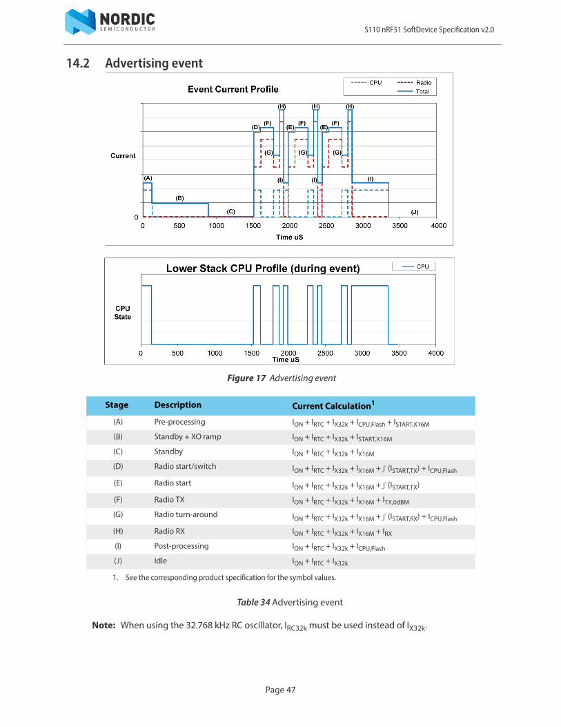
14.2 Advertising event
Figure 17 Advertising event
Table 34 Advertising event
Note: When using the 32.768 kHz RC oscillator, IRC32k must be used instead of IX32k.
Stage Description Current Calculation1
1. See the corresponding product specification for the symbol values.
(A) Pre-processing ION + IRTC + IX32k + ICPU,Flash + ISTART,X16M
(B) Standby + XO ramp ION + IRTC + IX32k + ISTART,X16M
(C) Standby ION + IRTC + IX32k + IX16M
(D) Radio start/switch ION + IRTC + IX32k + IX16M + ʃ (ISTART,TX) + ICPU,Flash
(E) Radio start ION + IRTC + IX32k + IX16M + ʃ (ISTART,TX)
(F) Radio TX ION + IRTC + IX32k + IX16M + ITX,0dBM
(G) Radio turn-around ION + IRTC + IX32k + IX16M + ʃ (ISTART,RX) + ICPU,Flash
(H) Radio RX ION + IRTC + IX32k + IX16M + IRX
(I) Post-processing ION + IRTC + IX32k + ICPU,Flash
(J) Idle ION + IRTC + IX32k
Page 47

S110 nRF51 SoftDevice Specification v2.0
15 SoftDevice identification and revision schemeThe SoftDevices will be identified by the SoftDevice part code, a chip series identifier or qualified chip part code (for example nRF51 or nRF51822), and a version string.
For revisions of the SoftDevice that are production qualified, the version string consists of major, minor, and revision numbers only, as described in Table 35.
For revisions of the SoftDevice that are not production qualified, a build number and a test qualification level (alpha/beta) are appended to the version string.
For example: s110_nrf51822_1.2.3-4.alpha, where major = 1, minor = 2, revision = 3, build number = 4 and test qualification level is alpha. Additional SoftDevice revision examples are given in Table 36.
Table 35 Revision scheme
Table 36 SoftDevice revision examples
Revision Description
Major increments Modifications to the API or the function or behavior of the implementation or part of it have changed.
Changes as per Minor Increment may have been made.
Application code will not be compatible without some modification.
Minor increments Additional features and/or API calls are available.
Changes as per Revision Increment may have been made.
Application code may have to be modified to take advantage of new features.
Revision increments Issues have been resolved or improvements to performance implemented.
Existing application code will not require any modification.
Build number increment (if present)
New build of non-production version.
Sequence number Description
s110_nrf51822_1.2.3-1.alpha Revision 1.2.3, first build, qualified at alpha level
s110_nrf51822_1.2.3-2.alpha Revision 1.2.3, second build, qualified at alpha level
s110_nrf51822_1.2.3-5.beta Revision 1.2.3, fifth build, qualified at beta level
s110_nrf51822_1.2.3 Revision 1.2.3, qualified at production level
Page 48

S110 nRF51 SoftDevice Specification v2.0
The test qualification levels are outlined in Table 37.
Table 37 Test qualification levels
15.1 MBR distribution and revision schemeThe MBR is distributed in each SoftDevice hex file. The version of the MBR distributed with the SoftDevice will be published in the release notes for the SoftDevice and uses the same major, minor and revision numbering scheme as described here.
15.2 Notification of SoftDevice revision updatesWhen new versions of a SoftDevice become available or the qualification status of a given revision of a SoftDevice is changed, product update notifications will be automatically forwarded, by email, to all users who have a profile configured to receive notifications from the Nordic Semiconductor website.
The SoftDevice will be updated with additional features and/or fixed issues if needed. Supported production versions of the SoftDevice will remain available after updates, so products do not need requalification on release of updates if the previous version is sufficiently feature complete for your product.
Qualification Description
Alpha Development release suitable for prototype application development.Hardware integration testing is not complete.Known issues may not be fixed between alpha releases.Incomplete and subject to change.
Beta Development release suitable for application development.In addition to alpha qualification:Hardware integration testing is complete.Stable, but may not be feature complete and may contain known issues.Protocol implementations are tested for conformance and interoperability.
Production Qualified release suitable for product integration.In addition to beta qualification:Hardware integration tested over supported range of operating conditions.Stable and complete with no known issues.Protocol implementations conform to standards.
Page 49
S110 nRF51 SoftDevice Specification v2.0
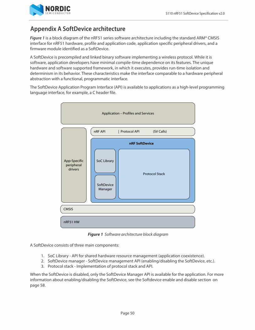
Appendix A SoftDevice architectureFigure 1 is a block diagram of the nRF51 series software architecture including the standard ARM® CMSIS interface for nRF51 hardware, profile and application code, application specific peripheral drivers, and a firmware module identified as a SoftDevice.
A SoftDevice is precompiled and linked binary software implementing a wireless protocol. While it is software, application developers have minimal compile-time dependence on its features. The unique hardware and software supported framework, in which it executes, provides run-time isolation and determinism in its behavior. These characteristics make the interface comparable to a hardware peripheral abstraction with a functional, programmatic interface.
The SoftDevice Application Program Interface (API) is available to applications as a high-level programming language interface, for example, a C header file.
Figure 1 Software architecture block diagram
A SoftDevice consists of three main components:
1. SoC Library - API for shared hardware resource management (application coexistence).2. SoftDevice manager - SoftDevice management API (enabling/disabling the SoftDevice, etc.).3. Protocol stack - Implementation of protocol stack and API.
When the SoftDevice is disabled, only the SoftDevice Manager API is available for the application. For more information about enabling/disabling the SoftDevice, see the Softdevice enable and disable section on page 58.
CMSIS
nRF API
Application – Profiles and Services
App-Specific peripheral
drivers
nRF51 HW
nRF SoftDevice
Protocol Stack
SoftDevice Manager
SoC Library
| Protocol API (SV Calls)
Page 50
S110 nRF51 SoftDevice Specification v2.0
SoC library
The SoC library provides functions for accessing shared hardware resources. The features of this library will vary between implementations of SoftDevices so detailed descriptions of the SoC library API are made available with the Software Development Kits (SDK) specific to each SoftDevice. The following is a summary of common components in the library.
SoftDevice Manager
The SoftDevice Manager (SDM) API implements functions for controlling the state of the SoftDevice enabled/disabled. When enabled, the SDM configures low frequency clock (LFCLK) source, interrupt management and the embedded protocol stack.
Detailed documentation of the SDM API is made available with the Software Development Kits (SDK) specific to each SoftDevice.
Protocol stack
The major component in each SoftDevice is a wireless protocol stack providing abstract control of the RF transceiver features for wireless applications. For example, fully qualified Bluetooth low energy and ANT™ protocols layers may be implemented in a SoftDevice to provide application developers with an out-of-the-box solution for applications using standard 2.4 GHz protocols.
Application Program Interface (API)
In addition, to a Protocol API enabling wireless applications, there is a nRF API that supports both the SoftDevice manager and the SoC library. The nRF API is consistent across SoftDevices in the nRF51 range of ANT™ and Bluetooth products for code compatibility.
The SoftDevice API is implemented using thread-safe Supervisor Calls (SVC). All application interaction with the stack and libraries is asynchronous and event driven. From the application this looks like regular functions, but no compiling or linking is required. All SVC interface functions will be provided through header files for the SDM, SoC Library, and protocol(s).
SV calls are conceptually software triggered interrupts with a procedure call standard for parameter passing and return values. Each API call generates an interrupt allowing single-thread API context and SoftDevice function locations to be independent from the application perspective at compile-time. SoftDevice API functions can only be called from lower interrupt priority when compared to the SVC priority. See the Exception (interrupt) management with a SoftDevice section on page 54.
Component Description
NVIC Wrapper functions for the CMSIS NVIC functions provided by ARM®.Note: To ensure reliable usage of the SoftDevice you must use the wrapper functions when the SoftDevice is enabled.
MUTEX Disabling interrupts shall not be done while the SoftDevice is enabled. Mutex functions have been implemented to provide safe regions.
RAND Random number generator - hardware sharing between SoftDevice and application.
POWER Power management - Functions for power management.
CLOCK Clock management – Functions for managing clock sources.
PPI Safe PPI access to dedicated Application PPI channels.
PWR_MNG Power management support (not a full implementation) for the application.
Page 51
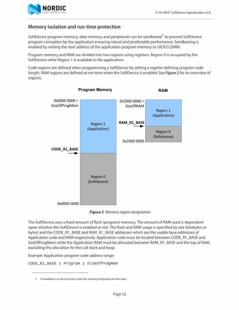
S110 nRF51 SoftDevice Specification v2.0
Memory isolation and run-time protection
SoftDevice program memory, data memory and peripherals can be sandboxed1 to prevent SoftDevice program corruption by the application ensuring robust and predictable performance. Sandboxing is enabled by writing the start address of the application program memory to UICR.CLENR0.
Program memory and RAM are divided into two regions using registers. Region 0 is occupied by the SoftDevice while Region 1 is available to the application.
Code regions are defined when programming a SoftDevice by setting a register defining program code length. RAM regions are defined at run-time when the SoftDevice is enabled. See Figure 2 for an overview of regions.
Figure 2 Memory region designation
The SoftDevice uses a fixed amount of flash (program) memory. The amount of RAM used is dependent upon whether the SoftDevice is enabled or not. The flash and RAM usage is specified by size (kilobytes or bytes) and the CODE_R1_BASE and RAM_R1_BASE addresses which are the usable base addresses of Application code and RAM respectively. Application code must be located between CODE_R1_BASE and SizeOfProgMem while the Application RAM must be allocated between RAM_R1_BASE and the top of RAM, excluding the allocation for the call stack and heap.
Example Application program code address range:
CODE_R1_BASE ≤ Program ≤ SizeOfProgMem
1. A sandbox is a set of access rules for memory imposed on the user.
Region 0(Softdevice)
Region 1(Application)
CODE_R1_BASE
0x0000 0000
0x0000 0000 +SizeOfProgMem
Program Memory RAM
Region 0(Softdevice)
Region 1(Application)
RAM_R1_BASE
0x2000 0000
0x2000 0000 +SizeOfRAM
Page 52
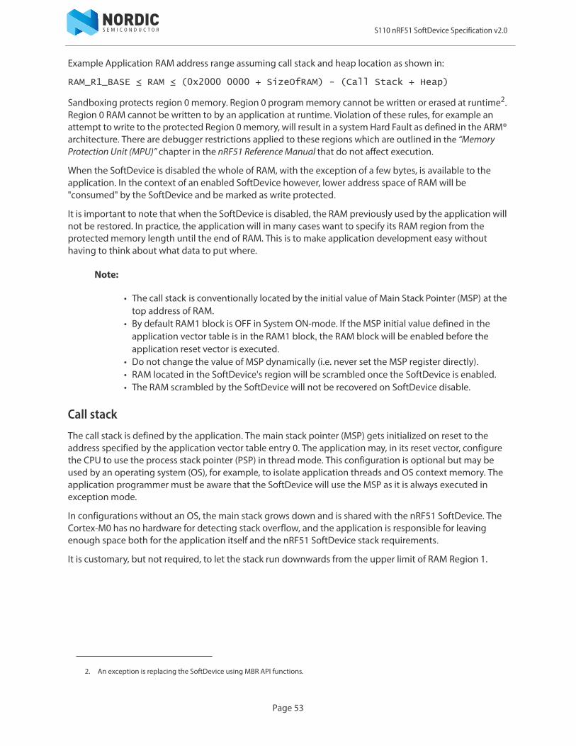
S110 nRF51 SoftDevice Specification v2.0
Example Application RAM address range assuming call stack and heap location as shown in:
RAM_R1_BASE ≤ RAM ≤ (0x2000 0000 + SizeOfRAM) - (Call Stack + Heap)
Sandboxing protects region 0 memory. Region 0 program memory cannot be written or erased at runtime2. Region 0 RAM cannot be written to by an application at runtime. Violation of these rules, for example an attempt to write to the protected Region 0 memory, will result in a system Hard Fault as defined in the ARM® architecture. There are debugger restrictions applied to these regions which are outlined in the “Memory Protection Unit (MPU)” chapter in the nRF51 Reference Manual that do not affect execution.
When the SoftDevice is disabled the whole of RAM, with the exception of a few bytes, is available to the application. In the context of an enabled SoftDevice however, lower address space of RAM will be "consumed" by the SoftDevice and be marked as write protected.
It is important to note that when the SoftDevice is disabled, the RAM previously used by the application will not be restored. In practice, the application will in many cases want to specify its RAM region from the protected memory length until the end of RAM. This is to make application development easy without having to think about what data to put where.
Note:
• The call stack is conventionally located by the initial value of Main Stack Pointer (MSP) at the top address of RAM.
• By default RAM1 block is OFF in System ON-mode. If the MSP initial value defined in the application vector table is in the RAM1 block, the RAM block will be enabled before the application reset vector is executed.
• Do not change the value of MSP dynamically (i.e. never set the MSP register directly).• RAM located in the SoftDevice's region will be scrambled once the SoftDevice is enabled.• The RAM scrambled by the SoftDevice will not be recovered on SoftDevice disable.
Call stack
The call stack is defined by the application. The main stack pointer (MSP) gets initialized on reset to the address specified by the application vector table entry 0. The application may, in its reset vector, configure the CPU to use the process stack pointer (PSP) in thread mode. This configuration is optional but may be used by an operating system (OS), for example, to isolate application threads and OS context memory. The application programmer must be aware that the SoftDevice will use the MSP as it is always executed in exception mode.
In configurations without an OS, the main stack grows down and is shared with the nRF51 SoftDevice. The Cortex-M0 has no hardware for detecting stack overflow, and the application is responsible for leaving enough space both for the application itself and the nRF51 SoftDevice stack requirements.
It is customary, but not required, to let the stack run downwards from the upper limit of RAM Region 1.
2. An exception is replacing the SoftDevice using MBR API functions.
Page 53
S110 nRF51 SoftDevice Specification v2.0
Figure 3 Call stack location example
With each release of a nRF51 SoftDevice its maximum (worst case) call stack requirement is specified, see the SoftDevice specification for more information. The SoftDevice uses the call stack when LowerStack or UpperStack events occur. These events are asynchronous to the application so the application programmer must reserve call stack for the application in addition to the call stack requirement for the SoftDevice.
Heap
At this time there is no heap required by nRF51 SoftDevices. The application is free to allocate and use a heap without disrupting the function of a SoftDevice.
Peripheral run-time protection
To prevent the application from accidentally disrupting the protocol stack in any way, the application sandbox also protects SoftDevice peripherals. Protected peripheral registers are readable by the application. As with program and data memory protection, an attempt to perform a write to a protected peripheral will result in a Hard Fault. Note that peripherals are only protected while the SoftDevice is enabled, otherwise they are available to the application. See the SoftDevice specification for an overview of the peripherals that are restricted by the SoftDevice.
Exception (interrupt) management with a SoftDevice
To implement Service Call (SVC) APIs and ensure that embedded protocol real-time requirements are met independent of application processing, the SoftDevice implements an exception model for execution as shown in Figure 4 on page 55. Care must be taken when selecting the correct interrupt priority for application events according to the guidelines that follow. The NVIC API to the SoC Library supports safe configuration of interrupt priority from the application.
The Cortex-M0 processor has four configurable interrupt priorities ranging from 0 to 3 (with 0 being highest priority). On reset, all interrupts are configured with the highest priority (0).
RAM
SoftdeviceRegion 0
ApplicationRegion 1
RAM_R1_BASE
0x2000 0000
0x2000 0000 + SizeOfRAM
*MSP initial value ‐
Call Stack
Page 54

S110 nRF51 SoftDevice Specification v2.0
The highest priority (LowerStack) is reserved by the SoftDevice to service real-time protocol timing requirements and thus must remain unused by the application programmer. The SoftDevice also reserves priority 2 (UpperStack (SVC) priority). This priority is used by higher level, deferrable, SoftDevice tasks and the API functions executed as SVC interrupts (see Interface section on page 51).
The application provides two configurable priorities, App(H) and App(L), in addition to the background level - main.
Figure 4 Exception model
As seen from the figure, App(H) is located between the two priorities reserved by the SoftDevice. This enables a low-latency application interrupt in order to support fast sensor interfaces. The App(H) will only experience latency from interrupts in the LowerStack priority, while App(L) can experience latency from LowerStack, App(H) and UpperStack context interrupts.
Lowest Priority
Highest Priority
Reset
Non-maskable Interrupt
Hard Fault
Cortex M0 Priorities
Softdevice priorities
-3
-2
-1
0
1
2
3
Bkgd
P1
P2
P3
MAIN
Application High - App(H)
UpperStack (SVC)
Application Low - App(L)
MAIN
P0 LowerStack
Page 55
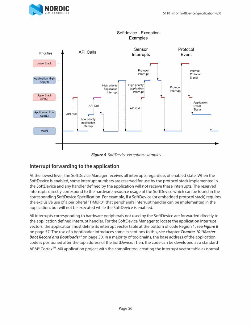
S110 nRF51 SoftDevice Specification v2.0
Figure 5 SoftDevice exception examples
Interrupt forwarding to the application
At the lowest level, the SoftDevice Manager receives all interrupts regardless of enabled state. When the SoftDevice is enabled, some interrupt numbers are reserved for use by the protocol stack implemented in the SoftDevice and any handler defined by the application will not receive these interrupts. The reserved interrupts directly correspond to the hardware resource usage of the SoftDevice which can be found in the corresponding SoftDevice Specification. For example, if a SoftDevice (or embedded protocol stack) requires the exclusive use of a peripheral “TIMER0”, that peripheral’s interrupt handler can be implemented in the application, but will not be executed while the SoftDevice is enabled.
All interrupts corresponding to hardware peripherals not used by the SoftDevice are forwarded directly to the application defined interrupt handler. For the SoftDevice Manager to locate the application interrupt vectors, the application must define its interrupt vector table at the bottom of code Region 1, see Figure 6 on page 57. The use of a bootloader introduces some exceptions to this, see chapter Chapter 10 “Master Boot Record and Bootloader” on page 30. In a majority of toolchains, the base address of the application code is positioned after the top address of the SoftDevice. Then, the code can be developed as a standard
ARM® CortexTM-M0 application project with the compiler tool creating the interrupt vector table as normal.
LowerStack
Application HighApp(H)
UpperStack (SVC)
Application LowApp(L)
MAIN
Softdevice - Exception Examples
Priorities
ProtocolInterrupt
ProtocolInterrupt
API Call
Low priorityapplicationinterrupt
API Call
High priority application
interrupt
API Call
High priority application
interrupt
InternalProtocolSignal
ApplicationEventSignal
ProtocolEventAPI Calls
Sensor Interrupts
Page 56

S110 nRF51 SoftDevice Specification v2.0
Figure 6 System and application interrupt vector tables
SVC interrupt is handled by SoftDevice manager and the SVC number inspected. If equal or greater than 0x10, the interrupt is processed by the SoftDevice. Values below 0x10 cause the SVC to be forwarded to the application. This allows the application to make use of a range of SVC numbers for its own purpose, for example, for an RTOS.
Note: While the CortexTM-M0 allows each interrupt to be assigned to an IRQ level 0 to 3, the priorities of the interrupts reserved by the SoftDevice cannot be changed. This includes the SVC interrupt. Handlers running at Application High level have neither access to SoftDevice functions nor to application specific SVCs or RTOS functions running at Application Low level.
If the SoftDevice is not enabled, all interrupts are immediately forwarded to the application specified handler. The exception to this is that SVC interrupts with an SVC number above or equal to 0x10 are not forwarded.
Events - SoftDevice to application
Software triggered interrupts in reserved IRQ slots are used to signal events from SoftDevice to application. For details on this technique and how to implement handling of these events, refer to the Software Development Kit (SDK) for your device.
Softdevice
Region 0
0x0000 0000
Empty Flash
Region 1
SizeOfProgMem
0x0000 00C0System / Softdevice Vector Table
CODE_R1_BASE
Program Memory
Page 57

S110 nRF51 SoftDevice Specification v2.0
SoftDevice enable and disable
Before enabling the SoftDevice, you cannot use any capabilities of the SoftDevice. This extends to the use of the SoC library and protocol stack functions. All of the chip’s resources are freely available to the application, with some exceptions:
• SVC numbers 0x10 to 0xFF are reserved.• SoftDevice program memory is reserved.• A few bytes of RAM are reserved.
Once the SoftDevice has been enabled, more restrictions apply:
• Some RAM will be reserved. • Some peripherals will be reserved.• Some of the peripherals that are reserved will have a SoC library interface.• Interrupts will not arrive in the application for reserved peripherals.• The reserved peripherals are reset upon SoftDevice disable.• nrf_nvic_ functions must be used instead of CMSIS NVIC_ functions for safe use of the
SoftDevice.• Maximum interrupt latency will be determined by the SoftDevice.
Power management
While the SoftDevice is disabled, the application must implement power management at the highest level. After a SoftDevice is enabled, the POWER peripheral will be protected. This means that all interactions with the POWER peripheral must happen through the SoC Library Power API. This API provides an interface for turning on/off peripherals and checking the power status of peripherals that are not protected by the SoftDevice. The application will also have the ability to set the other registers in the peripheral and put the chip in System OFF.
- All Peripherals are available- RAM, with the exception of a few bytes, is available- All Interrupts are forwarded to the application- SDM API available
Disabled
- Some peripherals are protected by the softdevice, - Portion of RAM has been protected- Interrupts for protected peripherals are handled by the softdevice- SoC library and Protocol-stack APIs are available for the application
Enabled
Page 58

S110 nRF51 SoftDevice Specification v2.0
Error handling
All SoftDevice API functions return an error code on success and failure.
Hard Faults are triggered if an application attempts to access memory contrary to the sandbox rules or peripheral configurations at runtime.
An assertion mechanism through a registered callback can indicate fatal failures in the SoftDevice to the application.
Page 59