s4.3 altay optic-laser center capability to satellites emergencies
TRANSCRIPT
1
V.P. Aleshin, E.A. Grishin, V.D. Shargorodsky, D.D. Novgorodtsev
ALTAY OPTIC-LASER CENTER CAPABILITY TO SATELLITES EMERGENCIES ESTIMATION
Emergencies with satellites are one of the main causes of space debris. The presentation reviews
methods of satellite accident monitoring using photometric and adaptive optical system (AOS) information of the Altay Optical Laser Center (AOLC). For the first time in Russia simultaneous observations of artificial satellites with the help of AOS and the photometer is made at AOLC (using two telescopes on one mount). Cases of slow unstabilized motion, or regular rotation of the satellite about its center of mass, are considered. The analysis used information about the 3D shape of the satellite and astroballistics propagation of its movement. The presentation sets out the principles of optical images and photometric signals modeling (prognosis), based on modern software and hardware capabilities of the 3D graphics. With the help of the developed monitoring methods emergencies with CORONAS - Photon, GEO-IK 2, Express AM4 and Phobos-Grunt satellites were analyzed using the large volume of real information.
The report discusses the capabilities of the Altai-optical laser in terms of monitoring debris in space. First of all it considers the capabilities of the center to monitor spacecraft emergencies. An analysis of emergency situations is significant in terms of their resolving, determining causes and avoiding the same precedents in the future. The analysis of the accidents involving space objects terminated transmission of telemetry is of great difficulty. Recall the case of an accident with the orbital station Salyut-7. The carried-out analysis of the station motion relative to the center of mass (CM) allowed to perform operations which helped to restore the station. A particularly important and sophisticated case is the slow motion of the spacecraft relative to the CM: the estimation of its current orientation in space and the deployment of its systems, such as solar cells, radio, etc. Most effective in this case are optical observations using adaptive optics, allowing to obtain images of the spacecraft with a resolution approaching the diffraction limit.
Keywords: space debris, adaptive optics, spacecraft, an emergency situation, the orientation of the spacecraft, technical vision system.
2
The main parameters of the Altai Optical Laser Center in the problem of control of man-made space debris
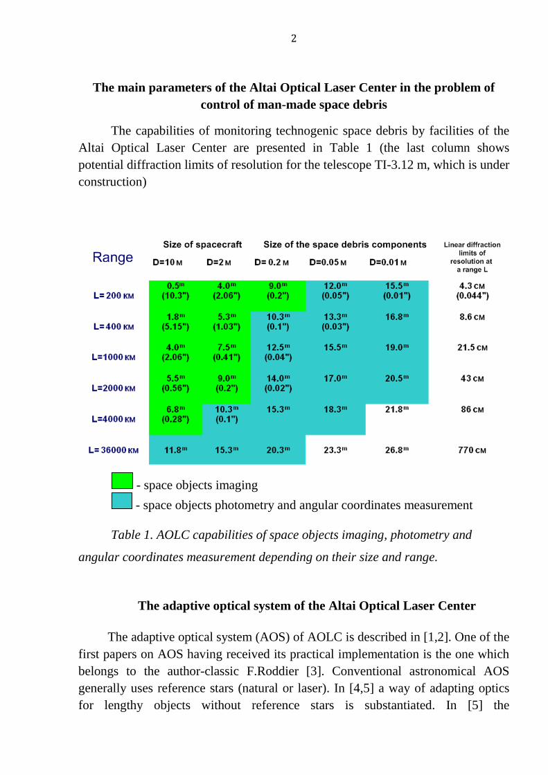
The capabilities of monitoring technogenic space debris by facilities of the Altai Optical Laser Center are presented in Table 1 (the last column shows potential diffraction limits of resolution for the telescope TI-3.12 m, which is under construction)
- space objects imaging - space objects photometry and angular coordinates measurement
Table 1. AOLC capabilities of space objects imaging, photometry and
angular coordinates measurement depending on their size and range.
The adaptive optical system of the Altai Optical Laser Center
The adaptive optical system (AOS) of AOLC is described in [1,2]. One of the first papers on AOS having received its practical implementation is the one which belongs to the author-classic F.Roddier [3]. Conventional astronomical AOS generally uses reference stars (natural or laser). In [4,5] a way of adapting optics for lengthy objects without reference stars is substantiated. In [5] the
3
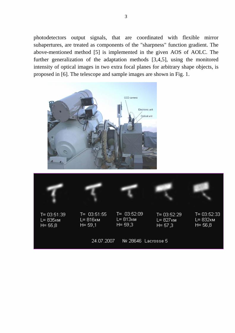
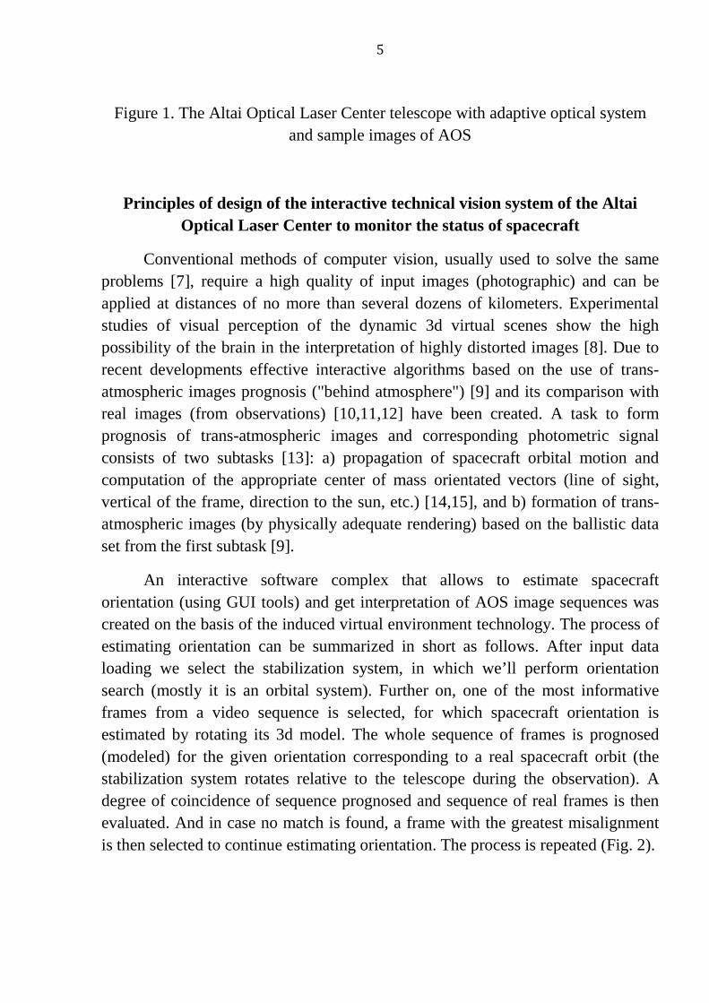
photodetectors output signals, that are coordinated with flexible mirror subapertures, are treated as components of the "sharpness" function gradient. The above-mentioned method [5] is implemented in the given AOS of AOLC. The further generalization of the adaptation methods [3,4,5], using the monitored intensity of optical images in two extra focal planes for arbitrary shape objects, is proposed in [6]. The telescope and sample images are shown in Fig. 1.
4
5
Figure 1. The Altai Optical Laser Center telescope with adaptive optical system and sample images of AOS
Principles of design of the interactive technical vision system of the Altai Optical Laser Center to monitor the status of spacecraft
Conventional methods of computer vision, usually used to solve the same problems [7], require a high quality of input images (photographic) and can be applied at distances of no more than several dozens of kilometers. Experimental studies of visual perception of the dynamic 3d virtual scenes show the high possibility of the brain in the interpretation of highly distorted images [8]. Due to recent developments effective interactive algorithms based on the use of trans-atmospheric images prognosis ("behind atmosphere") [9] and its comparison with real images (from observations) [10,11,12] have been created. A task to form prognosis of trans-atmospheric images and corresponding photometric signal consists of two subtasks [13]: a) propagation of spacecraft orbital motion and computation of the appropriate center of mass orientated vectors (line of sight, vertical of the frame, direction to the sun, etc.) [14,15], and b) formation of trans-atmospheric images (by physically adequate rendering) based on the ballistic data set from the first subtask [9].
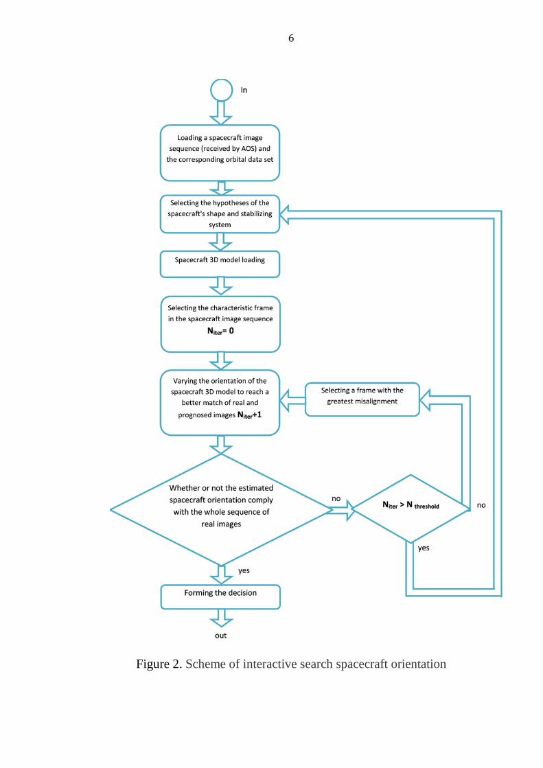
An interactive software complex that allows to estimate spacecraft orientation (using GUI tools) and get interpretation of AOS image sequences was created on the basis of the induced virtual environment technology. The process of estimating orientation can be summarized in short as follows. After input data loading we select the stabilization system, in which we’ll perform orientation search (mostly it is an orbital system). Further on, one of the most informative frames from a video sequence is selected, for which spacecraft orientation is estimated by rotating its 3d model. The whole sequence of frames is prognosed (modeled) for the given orientation corresponding to a real spacecraft orbit (the stabilization system rotates relative to the telescope during the observation). A degree of coincidence of sequence prognosed and sequence of real frames is then evaluated. And in case no match is found, a frame with the greatest misalignment is then selected to continue estimating orientation. The process is repeated (Fig. 2).
6
Figure 2. Scheme of interactive search spacecraft orientation
7
Image analysis in an emergency situation with the spacecraft "Koronos-Photon"
This unit was designed for astrophysical studies of the Sun. The orientation of the spacecraft in working order was determined by the Sun - measuring devices aimed at the Sun, the solar panels are orthogonal to a vector from the spacecraft towards the Sun. The orbit of the spacecraft is sunsynchronous. The spacecraft came into an emergency state in December 2009. The treatment of observation sessions on June 16, 17 and 22, 2010, allowed us to determine the orientation of the spacecraft and the degree of deviation of solar panels from the direction to the Sun.
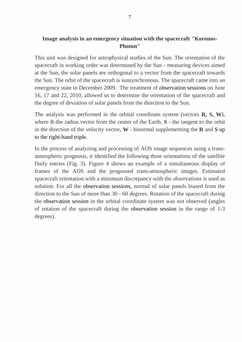
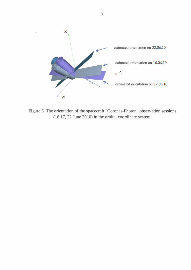
The analysis was performed in the orbital coordinate system (vectors R, S, W), where R-the radius vector from the center of the Earth, S - the tangent to the orbit in the direction of the velocity vector, W - binormal supplementing the R and S up to the right-hand triple.
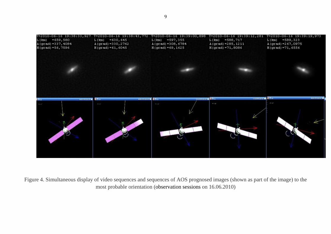
In the process of analyzing and processing of AOS image sequences using a trans-atmospheric prognosis, it identified the following three orientations of the satellite Daily entries (Fig. 3). Figure 4 shows an example of a simultaneous display of frames of the AOS and the prognosed trans-atmospheric images. Estimated spacecraft orientation with a minimum discrepancy with the observations is used as solution. For all the observation sessions, normal of solar panels biased from the direction to the Sun of more than 30 - 60 degrees. Rotation of the spacecraft during the observation session in the orbital coordinate system was not observed (angles of rotation of the spacecraft during the observation session in the range of 1-3 degrees).
8
Figure 3. The orientation of the spacecraft "Coronas-Photon" observation sessions (16.17, 22 June 2010) in the orbital coordinate system.
9
Figure 4. Simultaneous display of video sequences and sequences of AOS prognosed images (shown as part of the image) to the most probable orientation (observation sessions on 16.06.2010)
10
Analysis of the emergency with a spacecraft "Phobos-Grunt" in the period from November 29th to December 25th, 2011.
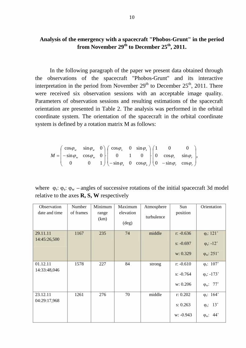
In the following paragraph of the paper we present data obtained through the observations of the spacecraft "Phobos-Grunt" and its interactive interpretation in the period from November 29th to December 25th, 2011. There were received six observation sessions with an acceptable image quality. Parameters of observation sessions and resulting estimations of the spacecraft orientation are presented in Table 2. The analysis was performed in the orbital coordinate system. The orientation of the spacecraft in the orbital coordinate system is defined by a rotation matrix M as follows:
−⋅
−⋅
−=
rr
rr
ss
ss
ww
ww
Mϕϕϕϕ
ϕϕ
ϕϕϕϕϕϕ
cossin0sincos0
001
cos0sin010
sin0cos
1000cossin0sincos
,
where φr: φs: φw – angles of successive rotations of the initial spacecraft 3d model relative to the axes R, S, W respectively
Observation date and time
Number of frames
Minimum range (km)
Maximum elevation
(deg)
Atmosphere
turbulence
Sun position
Orientation
29.11.11 14:45:26,500
1167 235 74 middle r: -0.636
s: -0.697
w: 0.329
φr: 121˚
φs: -12˚
φw: 251˚
01.12.11 14:33:48,046
1578 227 84 strong r: -0.610
s: -0.764
w: 0.206
φr: 107˚
φs: -173˚
φw: 77˚
23.12.11 04:29:17,968
1261 276 70 middle r: 0.202
s: 0.263
w: -0.943
φr: 164˚
φs: 13˚
φw: 44˚
11
24.12.11 04:13:43,859
2634 265 77 light r: 0.174
s: 0.354
w: -0.918
φr: 99˚
φs: 21˚
φw: 28˚
25.12.11 03:58:08,484
1199 259 82 middle r: 0.146
s: 0.441
w: -0.885
φr: 45˚
φs: 31˚
φw: -303˚
25.12.11 05:29:16,828
1791 256 78 light r: 0.252
s: 0.396
w: -0.882
φr: -116˚
φs: 39˚
φw: 238˚
Table 2.
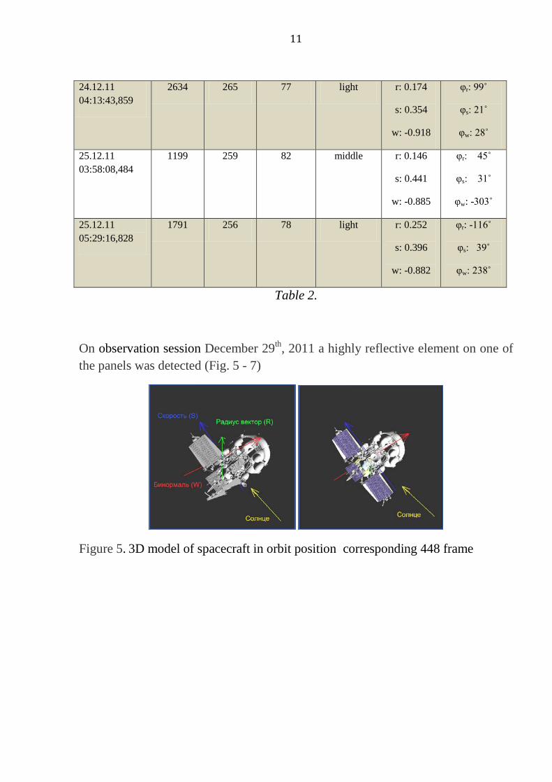
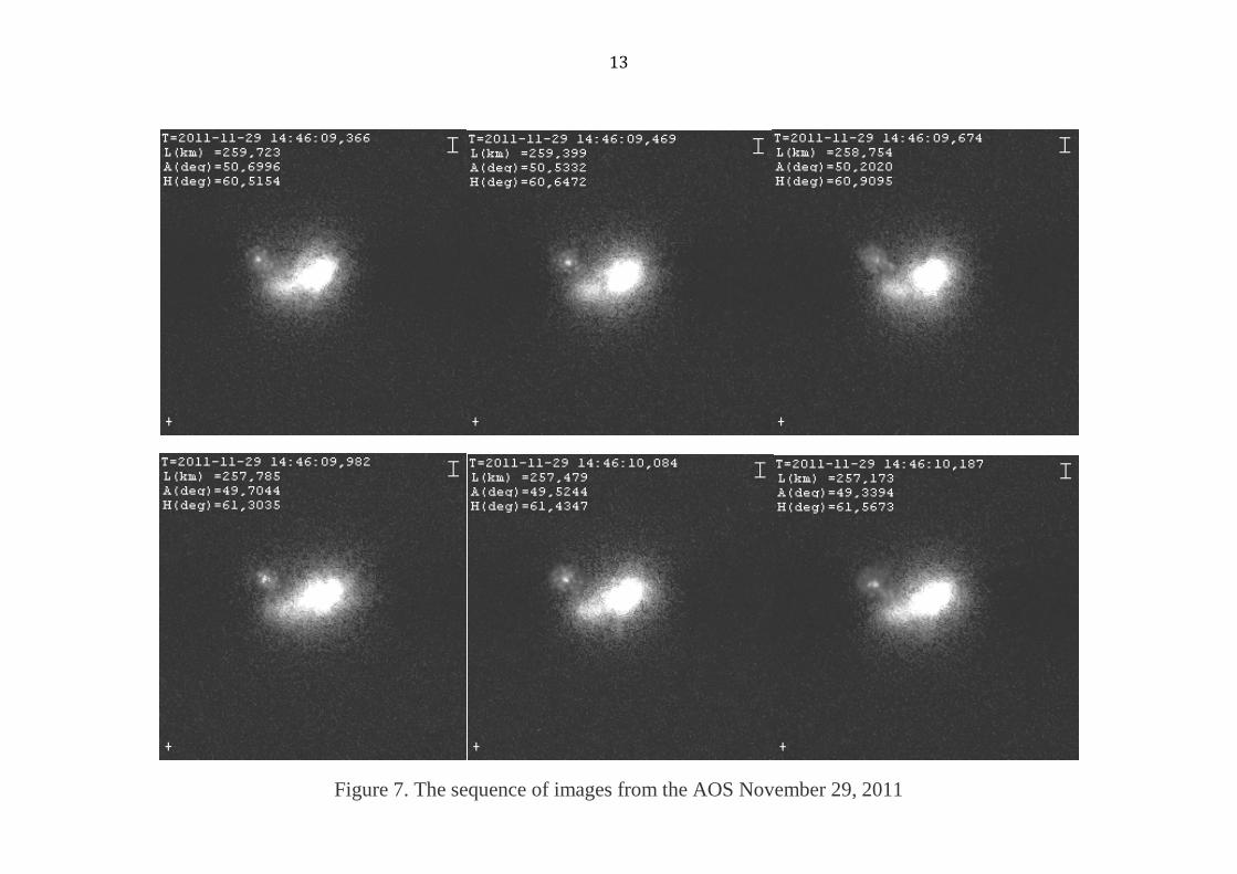
On observation session December 29th, 2011 a highly reflective element on one of the panels was detected (Fig. 5 - 7)
Figure 5. 3D model of spacecraft in orbit position corresponding 448 frame
12
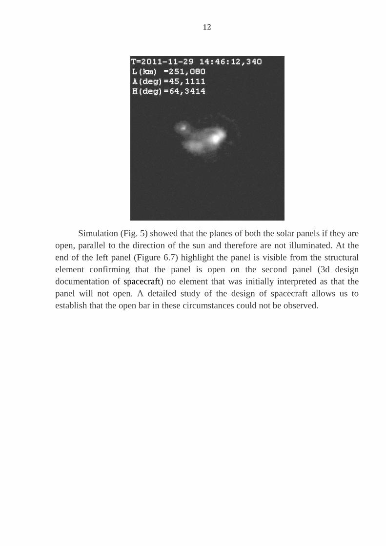
Simulation (Fig. 5) showed that the planes of both the solar panels if they are open, parallel to the direction of the sun and therefore are not illuminated. At the end of the left panel (Figure 6.7) highlight the panel is visible from the structural element confirming that the panel is open on the second panel (3d design documentation of spacecraft) no element that was initially interpreted as that the panel will not open. A detailed study of the design of spacecraft allows us to establish that the open bar in these circumstances could not be observed.
13
Figure 7. The sequence of images from the AOS November 29, 2011

14
15
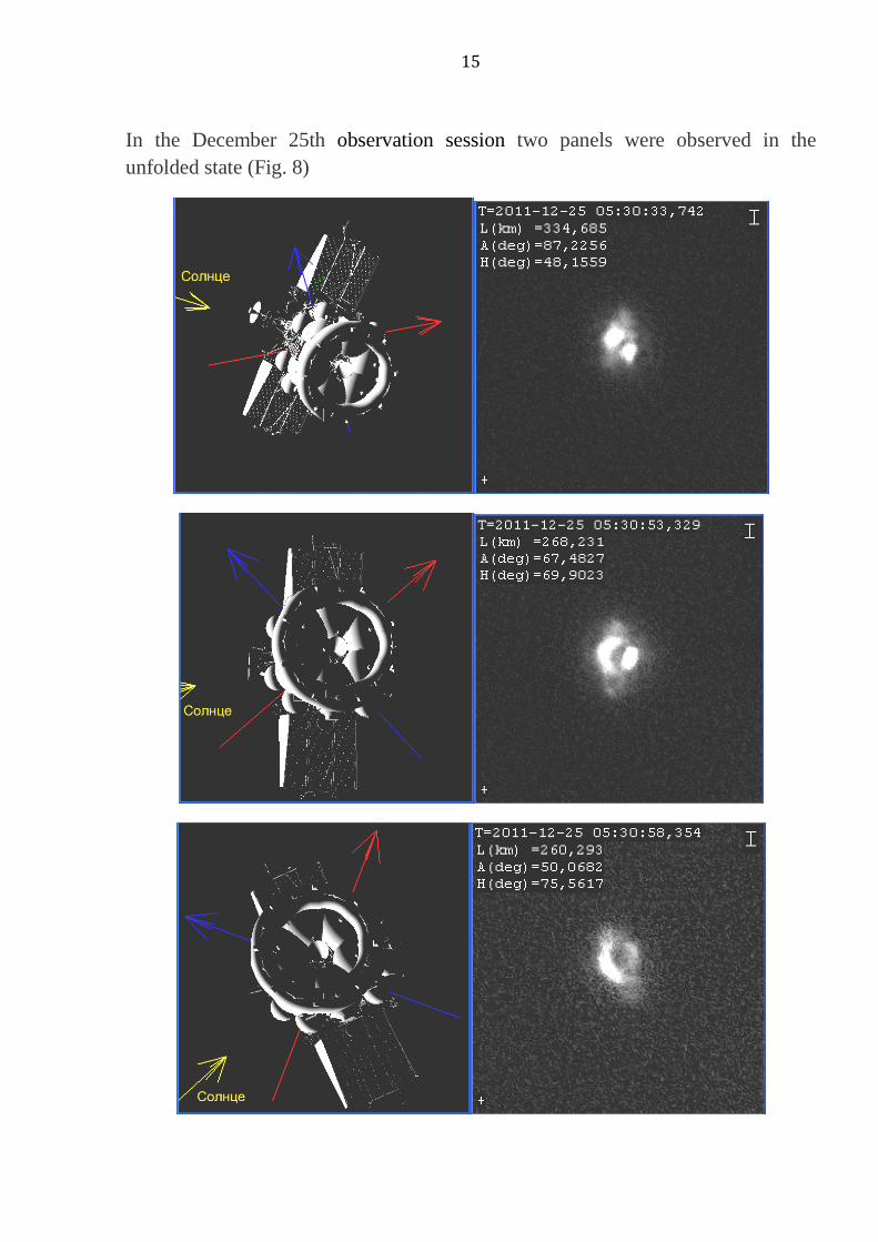
In the December 25th observation session two panels were observed in the unfolded state (Fig. 8)
16
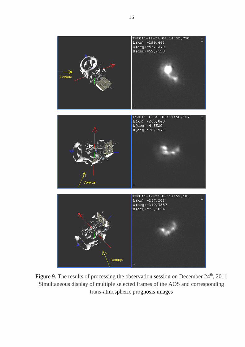
Figure 9. The results of processing the observation session on December 24th, 2011 Simultaneous display of multiple selected frames of the AOS and corresponding
trans-atmospheric prognosis images
17
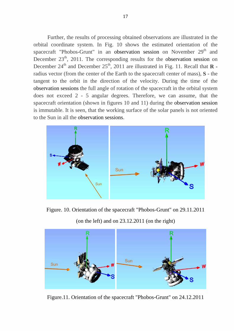
Further, the results of processing obtained observations are illustrated in the orbital coordinate system. In Fig. 10 shows the estimated orientation of the spacecraft "Phobos-Grunt" in an observation session on November 29th and December 23th, 2011. The corresponding results for the observation session on December 24th and December 25th, 2011 are illustrated in Fig. 11. Recall that R - radius vector (from the center of the Earth to the spacecraft center of mass), S - the tangent to the orbit in the direction of the velocity. During the time of the observation sessions the full angle of rotation of the spacecraft in the orbital system does not exceed 2 - 5 angular degrees. Therefore, we can assume, that the spacecraft orientation (shown in figures 10 and 11) during the observation session is immutable. It is seen, that the working surface of the solar panels is not oriented to the Sun in all the observation sessions.
Figure. 10. Orientation of the spacecraft "Phobos-Grunt" on 29.11.2011
(on the left) and on 23.12.2011 (on the right)
Figure.11. Orientation of the spacecraft "Phobos-Grunt" on 24.12.2011
18
(on the left) and on 25.12.2011 (on the right)
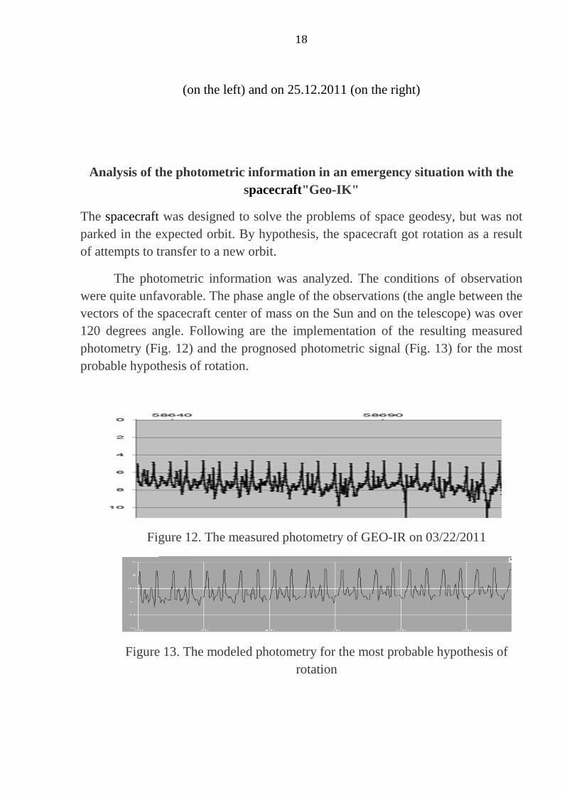
Analysis of the photometric information in an emergency situation with the spacecraft"Geo-IK"
The spacecraft was designed to solve the problems of space geodesy, but was not parked in the expected orbit. By hypothesis, the spacecraft got rotation as a result of attempts to transfer to a new orbit.
The photometric information was analyzed. The conditions of observation were quite unfavorable. The phase angle of the observations (the angle between the vectors of the spacecraft center of mass on the Sun and on the telescope) was over 120 degrees angle. Following are the implementation of the resulting measured photometry (Fig. 12) and the prognosed photometric signal (Fig. 13) for the most probable hypothesis of rotation.
Figure 12. The measured photometry of GEO-IR on 03/22/2011
Figure 13. The modeled photometry for the most probable hypothesis of rotation

19
Figure 14. The most likely parameters of the rotation
The analysis yielded the following most probable rotation parameters: a) the period of rotation - 7.5 sec., b) the axis of rotation is close to the axis of the housing unit, and c) the axis of rotation lies in the plane (Fig. 14) perpendicular to the bisector of the phase angle (the angle between the vectors spacecraft - the Sun and the satellite - telescope). In the process of modeling it was found that all other parameters were given the modeled photometry, very different from the measured (up to ambiguity). In the analysis of the photometric signal of rotating the spacecraft appears characteristic ambiguity problem solving associated with the ill posed inverse problem.
To solve this problem to be solved the following problems.
- Set accurate 3d model of the spacecraft with screen-vacuum thermal insulation. This problem is solved by means of laser scanning spacecraft before installing the fairing.
- Set the ellipsoid of− inertia of the spacecraft. Measured experimentally ore with the help of modeling.
- To measure the reflection characteristics of all materials of spacecraft construction in terms of bidirectional reflectance function (BRDF) [9, 13].
- To model the signal using algorithms ray tracing, for solving the problem "global illumination" [9, 13].
Simultaneous observations of the AOS and the photometer for the analysis of emergency with a spacecraft "Expres AM4" - upper stage "Breeze"
20
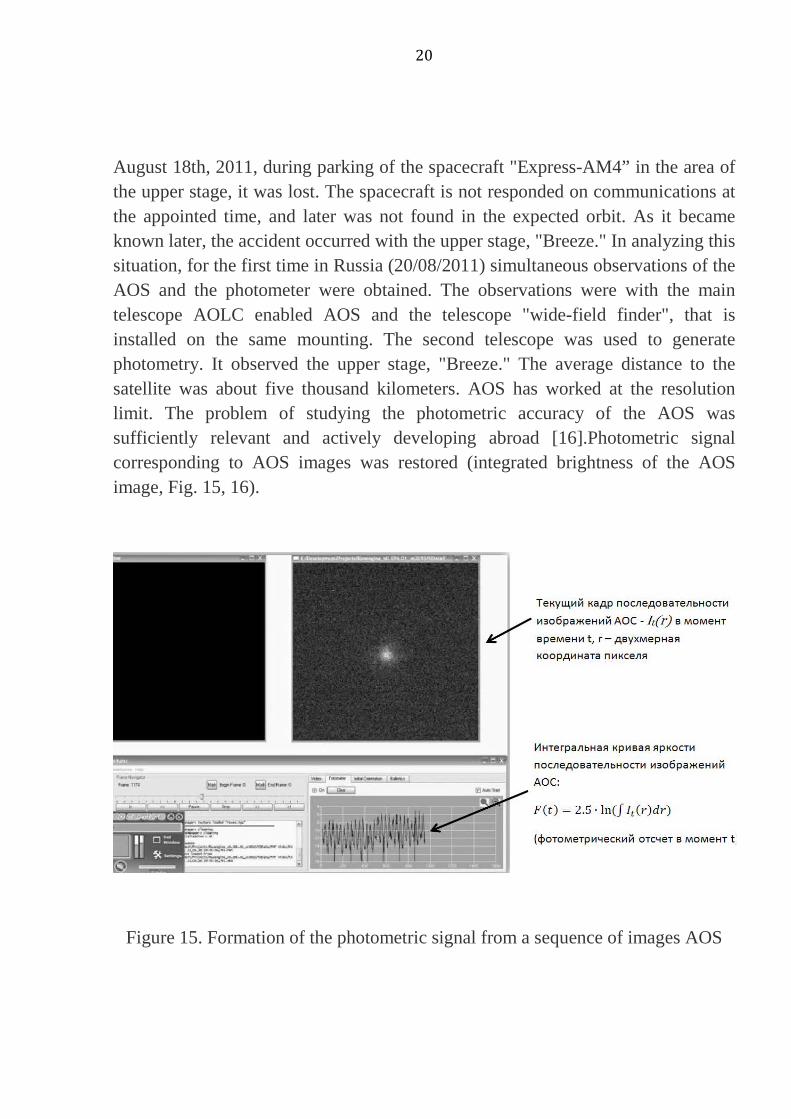
August 18th, 2011, during parking of the spacecraft "Express-AM4” in the area of the upper stage, it was lost. The spacecraft is not responded on communications at the appointed time, and later was not found in the expected orbit. As it became known later, the accident occurred with the upper stage, "Breeze." In analyzing this situation, for the first time in Russia (20/08/2011) simultaneous observations of the AOS and the photometer were obtained. The observations were with the main telescope AOLC enabled AOS and the telescope "wide-field finder", that is installed on the same mounting. The second telescope was used to generate photometry. It observed the upper stage, "Breeze." The average distance to the satellite was about five thousand kilometers. AOS has worked at the resolution limit. The problem of studying the photometric accuracy of the AOS was sufficiently relevant and actively developing abroad [16].Photometric signal corresponding to AOS images was restored (integrated brightness of the AOS image, Fig. 15, 16).
Figure 15. Formation of the photometric signal from a sequence of images AOS
21
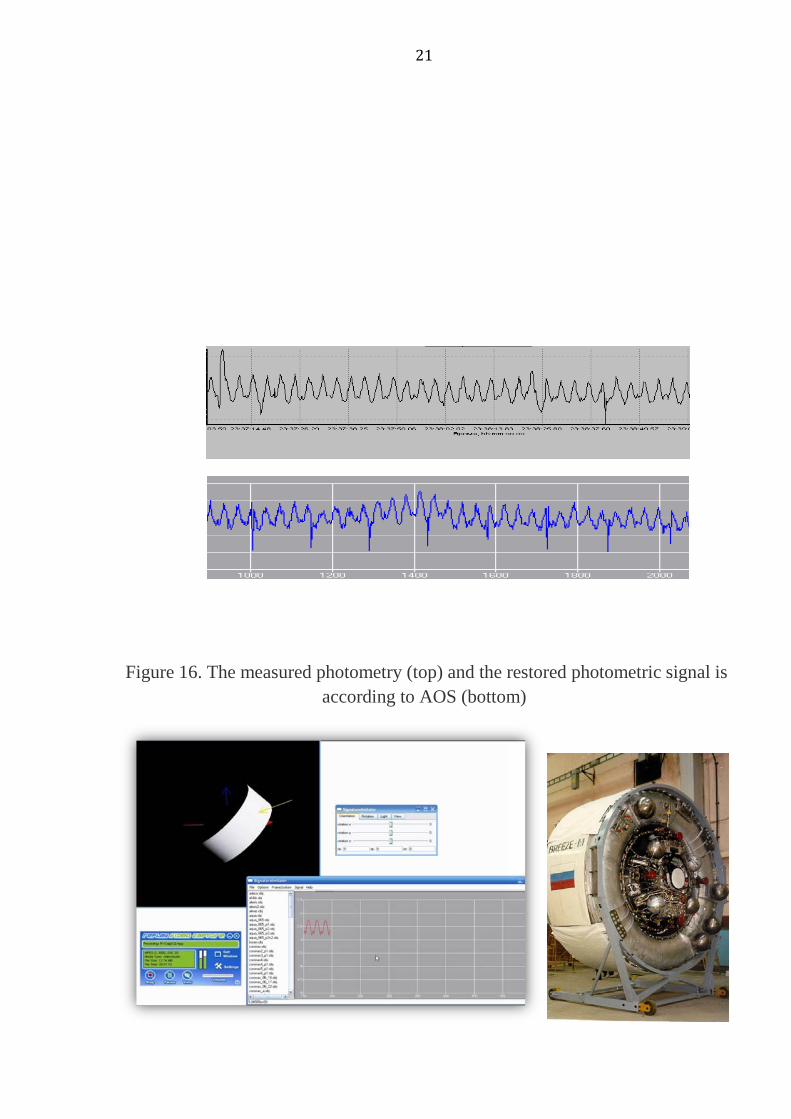
Figure 16. The measured photometry (top) and the restored photometric signal is according to AOS (bottom)
22
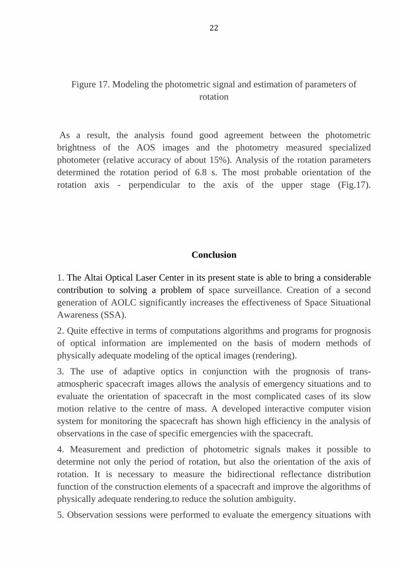
Figure 17. Modeling the photometric signal and estimation of parameters of rotation
As a result, the analysis found good agreement between the photometric brightness of the AOS images and the photometry measured specialized photometer (relative accuracy of about 15%). Analysis of the rotation parameters determined the rotation period of 6.8 s. The most probable orientation of the rotation axis - perpendicular to the axis of the upper stage (Fig.17).
Conclusion
1. The Altai Optical Laser Center in its present state is able to bring a considerable contribution to solving a problem of space surveillance. Creation of a second generation of AOLC significantly increases the effectiveness of Space Situational Awareness (SSA).
2. Quite effective in terms of computations algorithms and programs for prognosis of optical information are implemented on the basis of modern methods of physically adequate modeling of the optical images (rendering).
3. The use of adaptive optics in conjunction with the prognosis of trans-atmospheric spacecraft images allows the analysis of emergency situations and to evaluate the orientation of spacecraft in the most complicated cases of its slow motion relative to the centre of mass. A developed interactive computer vision system for monitoring the spacecraft has shown high efficiency in the analysis of observations in the case of specific emergencies with the spacecraft.
4. Measurement and prediction of photometric signals makes it possible to determine not only the period of rotation, but also the orientation of the axis of rotation. It is necessary to measure the bidirectional reflectance distribution function of the construction elements of a spacecraft and improve the algorithms of physically adequate rendering.to reduce the solution ambiguity.
5. Observation sessions were performed to evaluate the emergency situations with
23
the spacecraft "Coronas - Photon", "Phobos-Grunt", "GEO IR 2", "Express AM4"-upper stage "Breeze." We obtain estimates of the unregulated movement parameters and estimates of the regular rotation.
6. For the first time in Russia a AOS and photometer synchronous observation session was carried out, which allowed us to estimate a reasonably good degree of photometric accuracy of the adaptive optics (relative accuracy is about 15%). Simultaneous photometric measurements by specialized photometers can be used to estimate the integral brightness of the corresponding AOS images in photometric units
Acknowledgments
The authors thank Simonov G.V. and Razgulyaev J.P. for participating in experiments. The authors are grateful to V.S. Yurasov for any program and consulting.
Bibliography
1. Galkin A.A., Grishin E.A., Inshin P.P., Shargorodsky V.D. Spacecraft imaging using telescope of Altai Optical Laser Center with adaptive optics system. Space research. Vol. 46, № 3, May-June 2008, pp. 201-205
2. Aleshin V.P., Grishin E.A., Inshin P.P., Novgorodtsev D.D., Shargorodsky V.D. Estimation of capabilities of low-orbiting spacecrafts observations by adaptive optics system of the Altay optic-laser Center, The Proc. of International Conference “Near-Earth Astronomy-2009”, Kazan, 2009, pp. 22-28.
3. Roddier, F. (1988). "Curvature Sensing and Compensation - a New Concept in Adaptive Optics", Applied Optics 27(7): 1223-1225
4. Alexandrov A.B., Inshin P.P. Adaptive phase distortion correction of the radiation field from lengthy source with unknown shape, Radio Engineering and Electronics. 1990. № 6. pp. 1225
5. Alexandrov A.B., Inshin P.P. Adaptive operation based on sharpness function gradient in optical processor, Quantum Electronics. 1992. Т. 19. № 11. pp. 1122 - 1125.
6. Bakut P.A., Shumilov U.P., Ershova O.M. Amplitude-phase distortions estimation by extrafocal images. Proceedings of SPIE vol. 4493 pp. 256-260, 2001
24
7. Harry Voorhees, Robert Radke, Conrad Poelman, Automatic Reconstruction of Spacecraft 3D Shape from Imagery, 2008 Amos Conference, pp. 1-10.
8. Vladimir Aleshin, Valery Afanasiev, Alexander Bobkov, Stanislav Klimenko, Vitaly Kuliev, and Dmitry Novgorodtsev, Visual 3D Perception of Motion Environment and Visibility Factors in Virtual Space, Transaction on Computer Science, XVI, Lecture Notes on Computer Science 7380, Springer-Verlag Berlin Heidelberg pp. 17–33, 2012.
9. Novgorodtsev D.D., Aleshin V.P., Grishin E.A., Yurasov V.S., Methods and programs to forecast optical imaging and photometric signals of spacecrafts., An international journal “Electromagnetic Waves and Electronic”, 3’2011, Moscow, pp. 18-29
10. Aleshin V.P., Novgorodtsev D.D., Vygon V.G., Grishin E.A., Shargorodsky V.D., Satellites emergencies monitoring based on measurements and prognosis of photometric signals and adaptive optics imaging, Vestnik SibSAU, 6(39) 2011, pp. 159-165.
11. Aleshin V.P., Grishin E.A., Inshin P.P., Novgorodtsev D.D., Shargorodsky V.D., Evaluation of spacecrafts emergencies according to the adaptive optics images at the Altai optical-laser center, An international journal “Electromagnetic Waves and Electronic”, 3’2011, Moscow, pp. 30-35
12. Aleshin V.P., Afanasev V.O. Baygozin D.A., Baturin Y.M., Klimenko S.V. etc. The system visualization of induced virtual environment: the status of the project. The Proc. of 14 th Int. Conf. «GraphiCon-2004», MSU, 2004, - 318 pp., 12-15 pp.
13. Aleshin V.P., Klimenko S.V. Lavrov V.V., Novgorodtsev D.D., Simulation of optical imaging and photometric signals using a physically-accurate rendering and induced virtual environment technology / Questions of radio electronics. - № 4, 2007. - pp. 73-90.
14. Yurasov, V.S. “Universal semianalytic satellite motion propagation method applications in atmosphere”. Observations of artificial celestial bodies, Astronomical Council of USSR Academy of Sciences, Moscow, № 82, 1987.
15. Yurasov, V.S. ”Universal semianalytic satellite motion propagation method,” Proceedings of the Second U.S.-Russian Space Surveillance Workshop, Poznan, Poland, July 1996.
16. Lewis C. Roberts, Jr.,Nils H. Turner,,L. William Bradford, Theo A., Brummelaar, Ben R. Oppenheimer, Jeff R. Kuhn and Kathryn Whitman, Marshall D. Perrin and James R. Graham, Adaptive Optics Photometry and Astrometry of Binary Stars, The Astronomical Journal, 130:2262–2271, 2005 November
Aleshin Vladimir Petrovich – Head of the Division, Candidate of Technical Science, e-mail: [email protected]. Novgorodtsev Dmitry Dmitrievich – Head of the Workgroup, e-mail: [email protected].

25
Grishin Evgeny Alekseevich – Deputy Chief Designer, Chief Designer of Altay Optical Laser Center, Candidate of Technical Sciences, e-mail:[email protected].
Shargorodsky Victor Daniilovich – Chief Designer, Doctor of Technical Science, Professor, e-mail: [email protected].