s7-1200 motion control v13 - siemens ag · s7-1200 motion control v13 function manual, 02/2014,...
TRANSCRIPT

S7-1200 Motion Control V13
___________________
___________________
___________________
SIMATIC
STEP 7 S7-1200 Motion Control V13
Function Manual
02/2014 A5E03790551-03
Preface
Using S7-1200 Motion Control
1
S7-1200 Motion Control 2
Siemens AG Industry Sector Postfach 48 48 90026 NÜRNBERG GERMANY
A5E03790551-03 Ⓟ 01/2014 Technical data subject to change
Copyright © Siemens AG 2011 - 2014. All rights reserved
Legal information Warning notice system
This manual contains notices you have to observe in order to ensure your personal safety, as well as to prevent damage to property. The notices referring to your personal safety are highlighted in the manual by a safety alert symbol, notices referring only to property damage have no safety alert symbol. These notices shown below are graded according to the degree of danger.
DANGER indicates that death or severe personal injury will result if proper precautions are not taken.
WARNING indicates that death or severe personal injury may result if proper precautions are not taken.
CAUTION indicates that minor personal injury can result if proper precautions are not taken.
NOTICE indicates that property damage can result if proper precautions are not taken.
If more than one degree of danger is present, the warning notice representing the highest degree of danger will be used. A notice warning of injury to persons with a safety alert symbol may also include a warning relating to property damage.
Qualified Personnel The product/system described in this documentation may be operated only by personnel qualified for the specific task in accordance with the relevant documentation, in particular its warning notices and safety instructions. Qualified personnel are those who, based on their training and experience, are capable of identifying risks and avoiding potential hazards when working with these products/systems.
Proper use of Siemens products Note the following:
WARNING Siemens products may only be used for the applications described in the catalog and in the relevant technical documentation. If products and components from other manufacturers are used, these must be recommended or approved by Siemens. Proper transport, storage, installation, assembly, commissioning, operation and maintenance are required to ensure that the products operate safely and without any problems. The permissible ambient conditions must be complied with. The information in the relevant documentation must be observed.
Trademarks All names identified by ® are registered trademarks of Siemens AG. The remaining trademarks in this publication may be trademarks whose use by third parties for their own purposes could violate the rights of the owner.
Disclaimer of Liability We have reviewed the contents of this publication to ensure consistency with the hardware and software described. Since variance cannot be precluded entirely, we cannot guarantee full consistency. However, the information in this publication is reviewed regularly and any necessary corrections are included in subsequent editions.
S7-1200 Motion Control V13 Function Manual, 02/2014, A5E03790551-03 3
Preface
Preface
Purpose of this manual This document provides you with detailed information on S7-1200 Motion Control. The contents of this document correspond to the contents of the STEP 7 V13 online help with respect to contents and structure. Interaction with STEP 7 is required to understand many parts of this document.
This document is aimed at programmers of STEP 7 programs and at people who work in the areas of configuring, commissioning and servicing automation systems with motion control applications.
Required basic knowledge General knowledge in the fields of automation engineering and motion control is required to understand this document.
It is also essential to be familiar with the use of computers or programming devices under the Windows operating system.
Because S7-1200 Motion Control is based on STEP 7, you need knowledge of working with STEP 7.
Scope of this manual This manual is valid for STEP 7 V13.
Conventions This documentation contains pictures of the devices described. The pictures may differ in minor details from the devices supplied.
Please also observe notes labeled as follows:
Note
A note contains important information on the product described in the documentation, on the handling of the product or on the section of the documentation to which particular attention should be paid.
Preface
S7-1200 Motion Control V13 4 Function Manual, 02/2014, A5E03790551-03
Further support If you have any questions relating to the products described in this manual, and do not find the answers in this documentation, please contact your Siemens partner at our local offices.
You will find information on who to contact at:
(http://www.siemens.com/automation/partner)
A signpost to the documentation of the various SIMATIC products and systems is available at:
(http://www.siemens.com/simatic-tech-doku-portal)
You will find the online catalog and order system at:
(http://mall.automation.siemens.com)
Training center We offer a range of courses to help get you started with the S7 programmable controller. Please contact your regional training center or the central Training center (http://support.automation.siemens.com/WW/view/en/24486113).
Security information Siemens provides products and solutions with industrial security functions that support the secure operation of plants, solutions, machines, equipment and/or networks. They are important components in a holistic industrial security concept. With this in mind, Siemens’ products and solutions undergo continuous development. Siemens recommends strongly that you regularly check for product updates.
For the secure operation of Siemens products and solutions, it is necessary to take suitable preventive action (e.g. cell protection concept) and integrate each component into a holistic, state-of-the-art industrial security concept. Third-party products that may be in use should also be considered. You can find more information about industrial security on the Internet (http://www.siemens.com/industrialsecurity).
To stay informed about product updates as they occur, sign up for a product-specific newsletter. You can find more information on the Internet (http://support.automation.siemens.com).
S7-1200 Motion Control V13 Function Manual, 02/2014, A5E03790551-03 5
Table of contents
Preface ...................................................................................................................................................... 3
1 Using S7-1200 Motion Control ................................................................................................................... 9
1.1 Introduction .................................................................................................................................... 9 1.1.1 Motion functionality of the CPU S7-1200 ....................................................................................... 9 1.1.2 Hardware components for motion control .................................................................................... 10
1.2 Basics for working with S7-1200 Motion Control ......................................................................... 12 1.2.1 CPU outputs relevant for motion control (technology version V4) ............................................... 12 1.2.2 How the pulse interface works ..................................................................................................... 15 1.2.3 Relationship between the signal type and the direction of travel ................................................. 16 1.2.4 Hardware and software limit switches ......................................................................................... 20 1.2.5 Jerk limit ....................................................................................................................................... 21 1.2.6 Homing ......................................................................................................................................... 22
1.3 Guidelines on use of motion control ............................................................................................ 23
1.4 Using versions.............................................................................................................................. 24 1.4.1 Overview of versions .................................................................................................................... 24 1.4.2 Changing a technology version .................................................................................................... 26 1.4.3 Compatibility list of tags ............................................................................................................... 27 1.4.4 Status of limit switch .................................................................................................................... 30
1.5 Positioning axis technology object ............................................................................................... 31 1.5.1 Integration of the positioning axis technology object ................................................................... 31 1.5.2 Tools of the positioning axis technology object ........................................................................... 35 1.5.3 Adding a positioning axis technology object ................................................................................ 37 1.5.4 Configuring the positioning axis technology object ...................................................................... 38 1.5.4.1 Working with the configuration dialog .......................................................................................... 38 1.5.4.2 Compare values ........................................................................................................................... 39 1.5.4.3 Basic parameters ......................................................................................................................... 40 1.5.4.4 Extended parameters ................................................................................................................... 43
1.6 Technology object command table .............................................................................................. 65 1.6.1 Use of the command table technology object .............................................................................. 65 1.6.2 Command table technology object tools ...................................................................................... 65 1.6.3 Adding the technological object command table ......................................................................... 66 1.6.4 Configuring the command table technology object ...................................................................... 67 1.6.4.1 Working with the configuration dialog .......................................................................................... 67 1.6.4.2 Compare values ........................................................................................................................... 68 1.6.4.3 Basic parameters ......................................................................................................................... 69 1.6.4.4 Extended parameters ................................................................................................................... 83
1.7 Download to CPU ........................................................................................................................ 86
1.8 Commissioning the axis - Axis control panel ............................................................................... 88
Table of contents
S7-1200 Motion Control V13 6 Function Manual, 02/2014, A5E03790551-03
1.9 Parameter view ........................................................................................................................... 91 1.9.1 Introduction to the parameter view .............................................................................................. 91 1.9.2 Structure of the parameter view .................................................................................................. 93 1.9.2.1 Toolbar ........................................................................................................................................ 93 1.9.2.2 Navigation ................................................................................................................................... 94 1.9.2.3 Parameter table ........................................................................................................................... 95 1.9.3 Opening the parameter view ....................................................................................................... 97 1.9.4 Default setting of the parameter view ......................................................................................... 98 1.9.5 Working with the parameter view .............................................................................................. 100 1.9.5.1 Overview ................................................................................................................................... 100 1.9.5.2 Filtering the parameter table ..................................................................................................... 101 1.9.5.3 Sorting the parameter table....................................................................................................... 102 1.9.5.4 Transferring parameter data to other editors ............................................................................ 102 1.9.5.5 Indicating errors ........................................................................................................................ 103 1.9.5.6 Editing start values in the project .............................................................................................. 104 1.9.5.7 Status of configuration (offline) ................................................................................................. 105 1.9.5.8 Monitoring values online in the parameter view ........................................................................ 106 1.9.5.9 Create snapshot of monitor values ........................................................................................... 107 1.9.5.10 Modifying values ....................................................................................................................... 108 1.9.5.11 Comparing values ..................................................................................................................... 110 1.9.5.12 Applying values from the online program as start values ......................................................... 112 1.9.5.13 Initializing setpoints in the online program ................................................................................ 113
1.10 Programming ............................................................................................................................. 114 1.10.1 Overview of the Motion Control statements .............................................................................. 114 1.10.2 Creating a user program ........................................................................................................... 115 1.10.3 Programming notes ................................................................................................................... 118 1.10.4 Behavior of the Motion Control commands after POWER OFF and restart ............................. 120 1.10.5 Monitoring active commands .................................................................................................... 121 1.10.5.1 Monitoring active commands .................................................................................................... 121 1.10.5.2 Motion control instructions with "Done" output parameter ........................................................ 121 1.10.5.3 Motion control instruction MC_MoveVelocity ............................................................................ 125 1.10.5.4 Motion control instruction MC_MoveJog ................................................................................... 128 1.10.6 Error displays of the Motion Control statements ....................................................................... 132
1.11 Axis - Diagnostics ...................................................................................................................... 134 1.11.1 Status and error bits (technology objects as of V4) .................................................................. 134 1.11.2 Motion status ............................................................................................................................. 137 1.11.3 Dynamics settings ..................................................................................................................... 138
1.12 Appendix ................................................................................................................................... 139 1.12.1 Using multiple axes with the same PTO ................................................................................... 139 1.12.2 Using multiple drives with the same PTO ................................................................................. 142 1.12.3 Tracking jobs from higher priority classes (execution levels) ................................................... 143 1.12.4 Special cases for use of software limit switches ....................................................................... 146 1.12.4.1 Software limit switches in conjunction with a homing operation ............................................... 146 1.12.4.2 Software limit switches and software limit switch position changes. ........................................ 150 1.12.4.3 Software limit switches in conjunction with dynamic changes .................................................. 151 1.12.5 Reducing velocity for a short positioning duration .................................................................... 153 1.12.6 Dynamic adjustment of start/stop velocity ................................................................................. 153 1.12.7 List of ErrorIDs and ErrorInfos (technology objects as of V4) ................................................... 154
Table of contents
S7-1200 Motion Control V13 Function Manual, 02/2014, A5E03790551-03 7
1.12.8 Tags of the positioning axis technology object as of V4 ............................................................ 165 1.12.8.1 Position tag as of V4 .................................................................................................................. 165 1.12.8.2 Velocity tag as of V4 .................................................................................................................. 166 1.12.8.3 Actor tags as of V4 ..................................................................................................................... 167 1.12.8.4 Sensor[1] tags as of V4 .............................................................................................................. 169 1.12.8.5 Units tag as of V4 ....................................................................................................................... 172 1.12.8.6 Mechanics tag as of V4 .............................................................................................................. 173 1.12.8.7 DynamicLimits tags as of V4 ...................................................................................................... 174 1.12.8.8 DynamicDefaults tags as of V4 .................................................................................................. 175 1.12.8.9 PositionLimitsSW tags as of V4 ................................................................................................. 176 1.12.8.10 PositionLimitsHW tags as of V4 ............................................................................................ 177 1.12.8.11 Homing tags as of V4............................................................................................................ 178 1.12.8.12 StatusPositioning tags as of V4 ............................................................................................ 180 1.12.8.13 StatusBits tags as of V4 ........................................................................................................ 181 1.12.8.14 ErrorBits tags as of V4 .......................................................................................................... 185 1.12.8.15 ControlPanel tags as of V4 ................................................................................................... 187 1.12.8.16 Internal tags as of V4 ............................................................................................................ 187 1.12.8.17 Update of the technology object tags ................................................................................... 187 1.12.9 Tags of the command table technology object as of V4 ............................................................ 188 1.12.9.1 Command[1...32] tags as of V4 ................................................................................................. 188 1.12.10 Versions V1...3 ........................................................................................................................... 189 1.12.10.1 CPU outputs relevant for motion control (technology version V1...3) ................................... 189 1.12.10.2 Configuration dialogs ............................................................................................................ 193 1.12.10.3 Diagnostics - Status and error bits ("Axis" technology object V1...3) ................................... 203 1.12.10.4 ErrorIDs and ErrorInfos ......................................................................................................... 206 1.12.10.5 Tag of the axis technology object V1...3 ............................................................................... 222 1.12.10.6 Tags of the command table technology object V1...3 ........................................................... 240
2 S7-1200 Motion Control ......................................................................................................................... 242
2.1 S7-1200 Motion Control V4 ........................................................................................................ 242 2.1.1 MC_Power .................................................................................................................................. 242 2.1.1.1 MC_Power: Enable, disable axis V4 .......................................................................................... 242 2.1.1.2 MC_Power: Function chart V4 ................................................................................................... 246 2.1.2 MC_Reset .................................................................................................................................. 247 2.1.2.1 MC_Reset: Acknowledge fault V4 ............................................................................................. 247 2.1.3 MC_Home .................................................................................................................................. 249 2.1.3.1 MC_Home: Home axes, set reference point V4 ........................................................................ 249 2.1.4 MC_Halt ..................................................................................................................................... 253 2.1.4.1 MC_Halt: Halt axes V4 ............................................................................................................... 253 2.1.4.2 MC_Halt: Function chart V4 ....................................................................................................... 255 2.1.5 MC_MoveAbsolute ..................................................................................................................... 256 2.1.5.1 MC_MoveAbsolute: Absolute positioning of axes V4 ................................................................ 256 2.1.5.2 MC_MoveAbsolute: Function chart V4 ...................................................................................... 258 2.1.6 MC_MoveRelative ...................................................................................................................... 260 2.1.6.1 MC_MoveRelative: Relative positioning of axes V4 .................................................................. 260 2.1.6.2 MC_MoveRelative: Function chart V4 ....................................................................................... 262 2.1.7 MC_MoveVelocity ...................................................................................................................... 264 2.1.7.1 MC_MoveVelocity: Move axes at preset rotational speed V4 ................................................... 264 2.1.7.2 MC_MoveVelocity: Function chart V4 ........................................................................................ 267 2.1.8 MC_MoveJog ............................................................................................................................. 268 2.1.8.1 MC_MoveJog: Move axes in jog mode V4 ................................................................................ 268 2.1.8.2 MC_MoveJog: Function chart V4 ............................................................................................... 271
Table of contents
S7-1200 Motion Control V13 8 Function Manual, 02/2014, A5E03790551-03
2.1.9 MC_CommandTable ................................................................................................................. 272 2.1.9.1 MC_CommandTable: Run axis commands as motion sequence V4 ....................................... 272 2.1.10 MC_ChangeDynamic ................................................................................................................ 275 2.1.10.1 MC_ChangeDynamic: Change dynamic settings of axis V4 ..................................................... 275 2.1.11 MC_ReadParam ........................................................................................................................ 278 2.1.11.1 MC_ReadParam: Continuously read motion data of a positioning axis V4 .............................. 278 2.1.12 MC_WriteParam ........................................................................................................................ 280 2.1.12.1 MC_WriteParam: Write tag of positioning axis V4 .................................................................... 280
2.2 S7-1200 Motion Control V1...3 .................................................................................................. 282 2.2.1 MC_Power ................................................................................................................................. 282 2.2.1.1 MC_Power: Enable, disable axis V1...3 .................................................................................... 282 2.2.1.2 MC_Power: Function chart V1...3 ............................................................................................. 286 2.2.2 MC_Reset.................................................................................................................................. 287 2.2.2.1 MC_Reset: Acknowledge fault V1...3 ........................................................................................ 287 2.2.3 MC_Home ................................................................................................................................. 289 2.2.3.1 MC_Home: Home axes, set reference point V1...3 .................................................................. 289 2.2.4 MC_Halt ..................................................................................................................................... 293 2.2.4.1 MC_Halt: Halt axes V1...3 ......................................................................................................... 293 2.2.4.2 MC_Halt: Function chart V1...3 ................................................................................................. 295 2.2.5 MC_MoveAbsolute .................................................................................................................... 296 2.2.5.1 MC_MoveAbsolute: Absolute positioning of axes V1...3 .......................................................... 296 2.2.5.2 MC_MoveAbsolute: Function chart V1...3 ................................................................................. 298 2.2.6 MC_MoveRelative ..................................................................................................................... 299 2.2.6.1 MC_MoveRelative: Relative positioning of axes V1...3 ............................................................ 299 2.2.6.2 MC_MoveRelative: Function chart V1...3 .................................................................................. 302 2.2.7 MC_MoveVelocity ..................................................................................................................... 304 2.2.7.1 MC_MoveVelocity: Move axes at preset rotational speed V1...3 .............................................. 304 2.2.7.2 MC_MoveVelocity: Function chart V1...3 .................................................................................. 307 2.2.8 MC_MoveJog ............................................................................................................................ 308 2.2.8.1 MC_MoveJog: Move axes in jog mode V1...3 ........................................................................... 308 2.2.8.2 MC_MoveJog: Function chart V1...3 ......................................................................................... 310 2.2.9 MC_CommandTable ................................................................................................................. 311 2.2.9.1 MC_CommandTable: Run axis commands as motion sequence V2...3 .................................. 311 2.2.10 MC_ChangeDynamic ................................................................................................................ 313 2.2.10.1 MC_ChangeDynamic: Change dynamic settings of axis V2...3 ................................................ 313
Index ...................................................................................................................................................... 316

S7-1200 Motion Control V13 Function Manual, 02/2014, A5E03790551-03 9
Using S7-1200 Motion Control 1 1.1 Introduction
1.1.1 Motion functionality of the CPU S7-1200 The TIA Portal, together with the "Motion Control" functionality of the CPU S7-1200, supports you in controlling stepper motors and servo motors with pulse interface:
● You configure the positioning axis and command table technology objects in the TIA Portal. The CPU S7-1200 uses these technology objects to control the pulse generator outputs that control the drives.
● In the user program you control the axis by means of Motion Control instructions and initiate motion commands of your drive.
You can find a multi-media introduction on the Internet
(http://www.automation.siemens.com/mcms/programmable-logic-controller/en/ simatic-s7-controller/s7-1200/Pages/Default.aspx).
See also Hardware components for motion control (Page 10)
Integration of the positioning axis technology object (Page 31)
Tools of the positioning axis technology object (Page 35)
Use of the command table technology object (Page 65)
Command table technology object tools (Page 65)
Using S7-1200 Motion Control 1.1 Introduction
S7-1200 Motion Control V13 10 Function Manual, 02/2014, A5E03790551-03
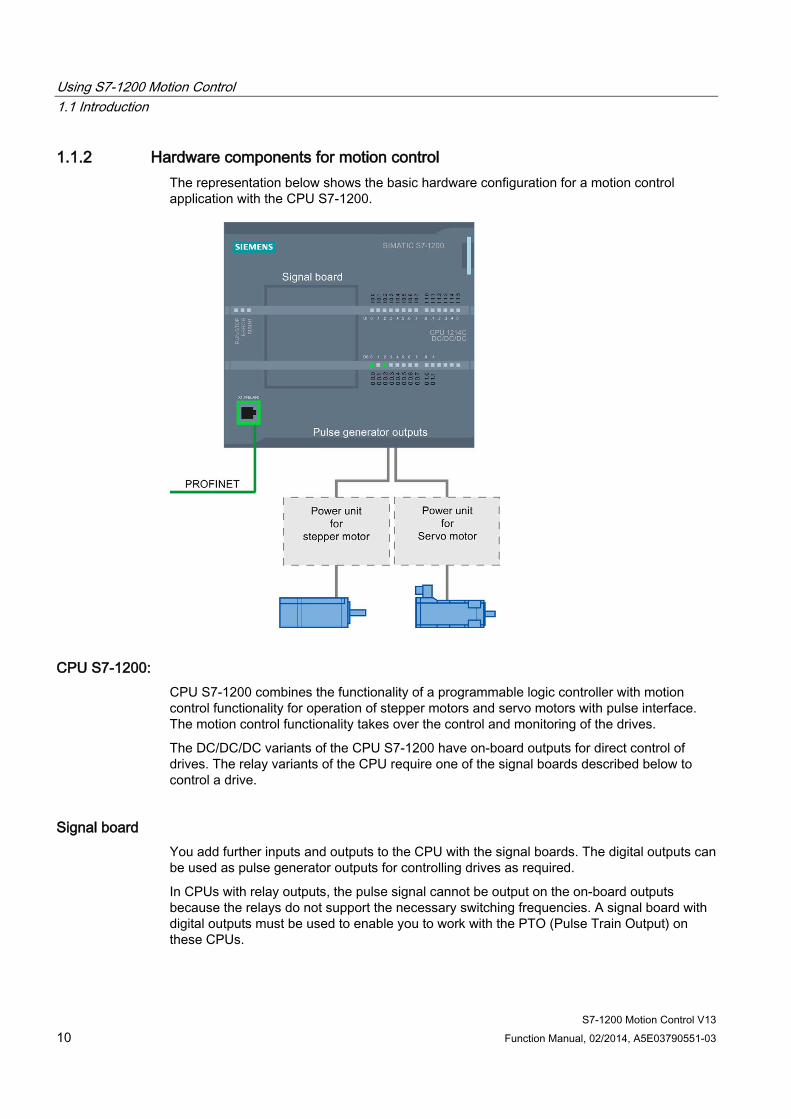
1.1.2 Hardware components for motion control The representation below shows the basic hardware configuration for a motion control application with the CPU S7-1200.
CPU S7-1200: CPU S7-1200 combines the functionality of a programmable logic controller with motion control functionality for operation of stepper motors and servo motors with pulse interface. The motion control functionality takes over the control and monitoring of the drives.
The DC/DC/DC variants of the CPU S7-1200 have on-board outputs for direct control of drives. The relay variants of the CPU require one of the signal boards described below to control a drive.
Signal board You add further inputs and outputs to the CPU with the signal boards. The digital outputs can be used as pulse generator outputs for controlling drives as required.
In CPUs with relay outputs, the pulse signal cannot be output on the on-board outputs because the relays do not support the necessary switching frequencies. A signal board with digital outputs must be used to enable you to work with the PTO (Pulse Train Output) on these CPUs.

Using S7-1200 Motion Control 1.1 Introduction
S7-1200 Motion Control V13 Function Manual, 02/2014, A5E03790551-03 11
PROFINET Use the PROFINET interface to establish the online connection between the CPU S7-1200 and the programming device. In addition to the online functions of the CPU, additional commissioning and diagnostic functions are available for motion control.
Ordering information for CPU Firmware V4 The order information listed below applies to the currently installed product phase (without any installed Hardware Support Packages) of the TIA Portal.
Name MLFB (order number) CPU 1211C DC/DC/DC 6ES7211-1AE40-0XB0 CPU 1211C AC/DC/RLY 6ES7211-1BE40-0XB0 CPU 1211C DC/DC/RLY 6ES7211-1HE40-0XB0 CPU 1212C DC/DC/DC 6ES7212-1AE40-0XB0 CPU 1212C AC/DC/RLY 6ES7212-1BE40-0XB0 CPU 1212C DC/DC/RLY 6ES7212-1HE40-0XB0 CPU 1214C DC/DC/DC 6ES7214-1AG40-0XB0 CPU 1214C AC/DC/RLY 6ES7214-1BG40-0XB0 CPU 1214C DC/DC/RLY 6ES7214-1HG40-0XB0 CPU 1214FC DC/DC/DC 6ES7214-1AF40-0XB0 CPU 1214FC DC/DC/RLY 6ES7214-1HF40-0XB0 CPU 1215C DC/DC/DC 6ES7215-1AG40-0XB0 CPU 1215C AC/DC/RLY 6ES7215-1BG40-0XB0 CPU 1215C DC/DC/RLY 6ES7215-1HG40-0XB0 CPU 1215FC DC/DC/DC 6ES7215-1AF40-0XB0 CPU 1215FC DC/DC/RLY 6ES7215-1HF40-0XB0 CPU 1217C DC/DC/DC 6ES7217-1AG40-0XB0 Signal board DI2/DO2 x DC24V 20kHz 6ES7223-0BD30-0XB0 Signal board DI2/DO2 x DC24V 200kHz 6ES7223-3BD30-0XB0 Signal board DO4 x DC24V 200kHz 6ES7222-1BD30-0XB0 Signal board DI2/DO2 x DC5V 200kHz 6ES7223-3AD30-0XB0 Signal board DO4 x DC5V 200kHz 6ES7222-1AD30-0XB0
Use a Hardware Support Package (HSP) to install new hardware components. The hardware component will then be available in the hardware catalog.
See also Motion functionality of the CPU S7-1200 (Page 9)
CPU outputs relevant for motion control (technology version V4) (Page 12)
Using S7-1200 Motion Control 1.2 Basics for working with S7-1200 Motion Control
S7-1200 Motion Control V13 12 Function Manual, 02/2014, A5E03790551-03
1.2 Basics for working with S7-1200 Motion Control
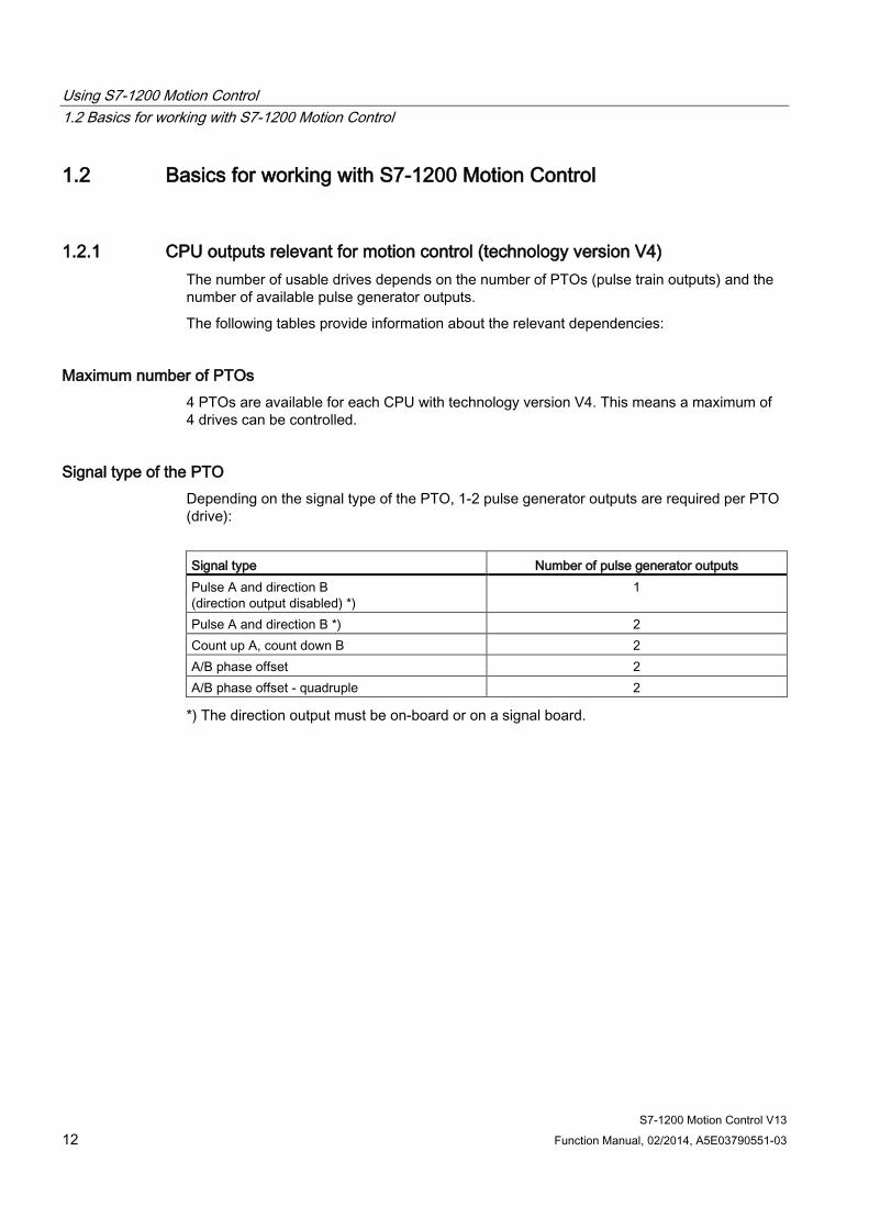
1.2.1 CPU outputs relevant for motion control (technology version V4) The number of usable drives depends on the number of PTOs (pulse train outputs) and the number of available pulse generator outputs.
The following tables provide information about the relevant dependencies:
Maximum number of PTOs 4 PTOs are available for each CPU with technology version V4. This means a maximum of 4 drives can be controlled.
Signal type of the PTO Depending on the signal type of the PTO, 1-2 pulse generator outputs are required per PTO (drive):
Signal type Number of pulse generator outputs Pulse A and direction B (direction output disabled) *)
1
Pulse A and direction B *) 2 Count up A, count down B 2 A/B phase offset 2 A/B phase offset - quadruple 2
*) The direction output must be on-board or on a signal board.
Using S7-1200 Motion Control 1.2 Basics for working with S7-1200 Motion Control
S7-1200 Motion Control V13 Function Manual, 02/2014, A5E03790551-03 13
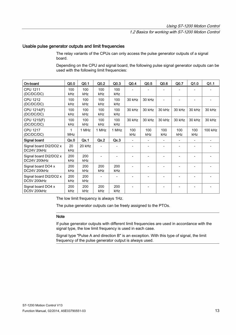
Usable pulse generator outputs and limit frequencies The relay variants of the CPUs can only access the pulse generator outputs of a signal board.
Depending on the CPU and signal board, the following pulse signal generator outputs can be used with the following limit frequencies:
On-board Q0.0 Q0.1 Q0.2 Q0.3 Q0.4 Q0.5 Q0.6 Q0.7 Q1.0 Q1.1 CPU 1211 (DC/DC/DC)
100 kHz
100 kHz
100 kHz
100 kHz
- - - - - -
CPU 1212 (DC/DC/DC)
100 kHz
100 kHz
100 kHz
100 kHz
30 kHz 30 kHz - - - -
CPU 1214(F) (DC/DC/DC)
100 kHz
100 kHz
100 kHz
100 kHz
30 kHz 30 kHz 30 kHz 30 kHz 30 kHz 30 kHz
CPU 1215(F) (DC/DC/DC)
100 kHz
100 kHz
100 kHz
100 kHz
30 kHz 30 kHz 30 kHz 30 kHz 30 kHz 30 kHz
CPU 1217 (DC/DC/DC)
1 MHz
1 MHz 1 MHz 1 MHz 100 kHz
100 kHz
100 kHz
100 kHz
100 kHz
100 kHz
Signal board Qx.0 Qx.1 Qx.2 Qx.3 - - - - - - Signal board DI2/DO2 x DC24V 20kHz
20 kHz
20 kHz - - - - - - - -
Signal board DI2/DO2 x DC24V 200kHz
200 kHz
200 kHz
- - - - - - - -
Signal board DO4 x DC24V 200kHz
200 kHz
200 kHz
200 kHz
200 kHz
- - - - - -
Signal board DI2/DO2 x DC5V 200kHz
200 kHz
200 kHz
- - - - - - - -
Signal board DO4 x DC5V 200kHz
200 kHz
200 kHz
200 kHz
200 kHz
- - - - - -
The low limit frequency is always 1Hz.
The pulse generator outputs can be freely assigned to the PTOs.
Note
If pulse generator outputs with different limit frequencies are used in accordance with the signal type, the low limit frequency is used in each case.
Signal type "Pulse A and direction B" is an exception. With this type of signal, the limit frequency of the pulse generator output is always used.

Using S7-1200 Motion Control 1.2 Basics for working with S7-1200 Motion Control
S7-1200 Motion Control V13 14 Function Manual, 02/2014, A5E03790551-03
Note Access to pulse generator outputs via the process image
The firmware takes control via the corresponding pulse generator and direction outputs if the PTO (Pulse Train Output) is selected and assigned to an axis.
With this takeover of the control function, the connection between the process image and I/O output is also disconnected. Although the user has the option of writing the process image of pulse generator and direction outputs via the user program or watch table, this is not transferred to the I/O output. Accordingly, it is also not possible to monitor the I/O output via the user program or watch table. The information read reflects the value of the process image and does not match the real status of the I/O output.
For all other CPU outputs that are not used permanently by the CPU firmware, the status of the I/O output can be controlled or monitored via the process image, as usual.
Outputs for drive signals For motion control, you can optionally parameterize a drive interface for "Drive enabled" and "Drive ready".
When using the drive interface the digital output for the drive enable and the digital input for "drive ready" can be freely selected.
Acceleration/deceleration limits The following limits apply to acceleration and deceleration:
Acceleration/deceleration Value Minimum acceleration/deceleration 5.0E-3 pulses/s2 Maximum acceleration/deceleration 9.5E+9 pulses/s2
Jerk limits The following limits apply to the jerk:
Jerk Value Minimum jerk 4.0E-3 pulses/s3 Maximum jerk 1.0E+10 pulses/s3
Using S7-1200 Motion Control 1.2 Basics for working with S7-1200 Motion Control
S7-1200 Motion Control V13 Function Manual, 02/2014, A5E03790551-03 15
See also CPU outputs relevant for motion control (technology version V1...3) (Page 189)
How the pulse interface works (Page 15)
Relationship between the signal type and the direction of travel (Page 16)
Hardware and software limit switches (Page 20)
Jerk limit (Page 21)
Homing (Page 22)
Hardware components for motion control (Page 10)
Integration of the positioning axis technology object (Page 31)
Tools of the positioning axis technology object (Page 35)
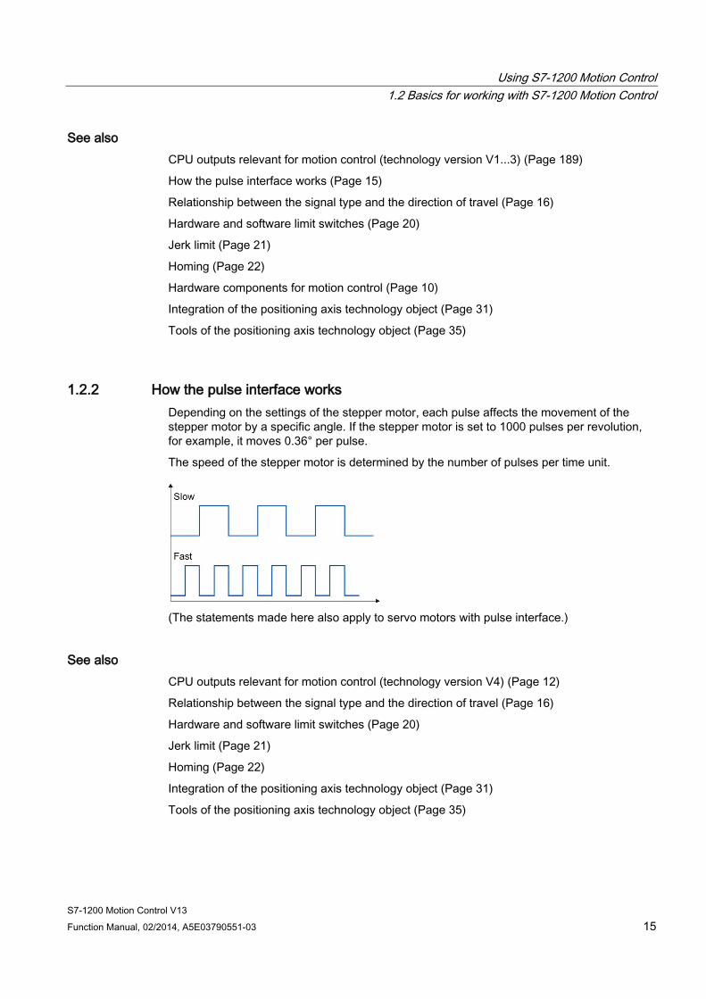
1.2.2 How the pulse interface works Depending on the settings of the stepper motor, each pulse affects the movement of the stepper motor by a specific angle. If the stepper motor is set to 1000 pulses per revolution, for example, it moves 0.36° per pulse.
The speed of the stepper motor is determined by the number of pulses per time unit.
(The statements made here also apply to servo motors with pulse interface.)
See also CPU outputs relevant for motion control (technology version V4) (Page 12)
Relationship between the signal type and the direction of travel (Page 16)
Hardware and software limit switches (Page 20)
Jerk limit (Page 21)
Homing (Page 22)
Integration of the positioning axis technology object (Page 31)
Tools of the positioning axis technology object (Page 35)
Using S7-1200 Motion Control 1.2 Basics for working with S7-1200 Motion Control
S7-1200 Motion Control V13 16 Function Manual, 02/2014, A5E03790551-03
1.2.3 Relationship between the signal type and the direction of travel The CPU outputs the velocity and direction of travel via two outputs.
The relationships between the configuration and direction of travel differ depending on the selected signal type. You can configure the following signal types in the axis configuration under "Basic parameters > General":
● "PTO (pulse A and direction B)"
● "PTO (count up A, count down B)" (as of V4)
● "PTO (A/B phase offset)" (as of V4)
● "PTO (A/B phase offset - quadruple)" (as of V4)
You configure the direction under "Extended Parameters > Mechanics" in the axis configuration. If you select the "Invert direction" option, the direction logic described below for the respective signal type is inverted.
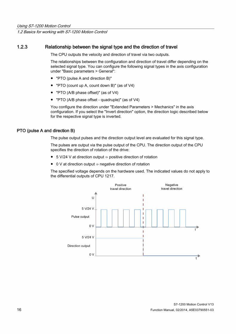
PTO (pulse A and direction B) The pulse output pulses and the direction output level are evaluated for this signal type.
The pulses are output via the pulse output of the CPU. The direction output of the CPU specifies the direction of rotation of the drive:
● 5 V/24 V at direction output ⇒ positive direction of rotation
● 0 V at direction output ⇒ negative direction of rotation
The specified voltage depends on the hardware used. The indicated values do not apply to the differential outputs of CPU 1217.
Using S7-1200 Motion Control 1.2 Basics for working with S7-1200 Motion Control
S7-1200 Motion Control V13 Function Manual, 02/2014, A5E03790551-03 17
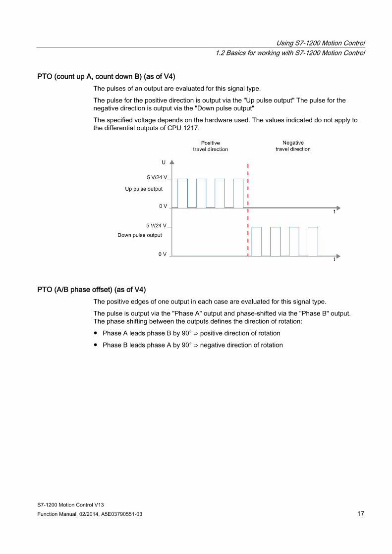
PTO (count up A, count down B) (as of V4) The pulses of an output are evaluated for this signal type.
The pulse for the positive direction is output via the "Up pulse output" The pulse for the negative direction is output via the "Down pulse output"
The specified voltage depends on the hardware used. The values indicated do not apply to the differential outputs of CPU 1217.
PTO (A/B phase offset) (as of V4) The positive edges of one output in each case are evaluated for this signal type.
The pulse is output via the "Phase A" output and phase-shifted via the "Phase B" output. The phase shifting between the outputs defines the direction of rotation:
● Phase A leads phase B by 90° ⇒ positive direction of rotation
● Phase B leads phase A by 90° ⇒ negative direction of rotation

Using S7-1200 Motion Control 1.2 Basics for working with S7-1200 Motion Control
S7-1200 Motion Control V13 18 Function Manual, 02/2014, A5E03790551-03
PTO (A/B phase offset - quadruple) (as of V4) The positive and negative edges of both outputs are evaluated for this signal type. A pulse period has four edges with two phases (A and B). The pulse frequency at the output is therefore reduced to a quarter.
The pulse is output via the "Phase A" output and phase-shifted via the "Phase B" output. The phase shifting between the outputs defines the direction of rotation:
● Phase A leads phase B by 90° ⇒ positive direction of rotation
● Phase B leads phase A by 90° ⇒ negative direction of rotation
The specified voltage depends on the hardware used. The indicated values do not apply to the differential outputs of CPU 1217.
Using S7-1200 Motion Control 1.2 Basics for working with S7-1200 Motion Control
S7-1200 Motion Control V13 Function Manual, 02/2014, A5E03790551-03 19
Invert direction If you select the "Invert rotation signal" option, the direction logic is inverted:
● PTO (pulse A and direction B)
– 0 V at direction output (low level) ⇒ positive direction of rotation
– 5 V/24 V at direction output (high level) ⇒ negative direction of rotation
The specified voltage depends on the hardware used. The voltages indicated do not apply to the differential outputs of CPU 1217.
● PTO (count up A, count down B)
The outputs "Pulse output down" and "Pulse output up" are swapped.
● PTO (A/B phase offset)
The "Phase A" and "Phase B" outputs are swapped.
● "PTO (A/B phase offset - quadruple)
The "Phase A" and "Phase B" outputs are swapped.
See also CPU outputs relevant for motion control (technology version V4) (Page 12)
How the pulse interface works (Page 15)
Hardware and software limit switches (Page 20)
Jerk limit (Page 21)
Homing (Page 22)
Integration of the positioning axis technology object (Page 31)
Tools of the positioning axis technology object (Page 35)
Using S7-1200 Motion Control 1.2 Basics for working with S7-1200 Motion Control
S7-1200 Motion Control V13 20 Function Manual, 02/2014, A5E03790551-03
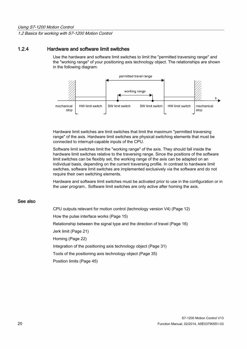
1.2.4 Hardware and software limit switches Use the hardware and software limit switches to limit the "permitted traversing range" and the "working range" of your positioning axis technology object. The relationships are shown in the following diagram:
Hardware limit switches are limit switches that limit the maximum "permitted traversing range" of the axis. Hardware limit switches are physical switching elements that must be connected to interrupt-capable inputs of the CPU.
Software limit switches limit the "working range" of the axis. They should fall inside the hardware limit switches relative to the traversing range. Since the positions of the software limit switches can be flexibly set, the working range of the axis can be adapted on an individual basis, depending on the current traversing profile. In contrast to hardware limit switches, software limit switches are implemented exclusively via the software and do not require their own switching elements.
Hardware and software limit switches must be activated prior to use in the configuration or in the user program.. Software limit switches are only active after homing the axis.
See also CPU outputs relevant for motion control (technology version V4) (Page 12)
How the pulse interface works (Page 15)
Relationship between the signal type and the direction of travel (Page 16)
Jerk limit (Page 21)
Homing (Page 22)
Integration of the positioning axis technology object (Page 31)
Tools of the positioning axis technology object (Page 35)
Position limits (Page 45)
Using S7-1200 Motion Control 1.2 Basics for working with S7-1200 Motion Control
S7-1200 Motion Control V13 Function Manual, 02/2014, A5E03790551-03 21
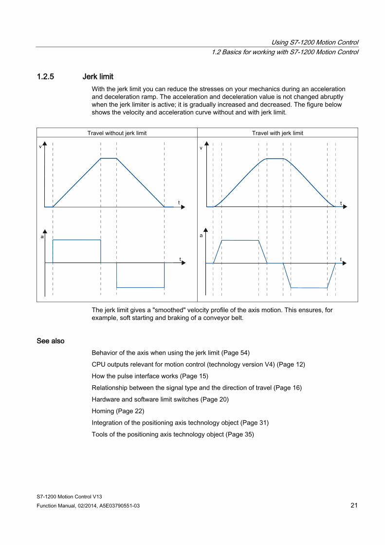
1.2.5 Jerk limit With the jerk limit you can reduce the stresses on your mechanics during an acceleration and deceleration ramp. The acceleration and deceleration value is not changed abruptly when the jerk limiter is active; it is gradually increased and decreased. The figure below shows the velocity and acceleration curve without and with jerk limit.
Travel without jerk limit Travel with jerk limit
The jerk limit gives a "smoothed" velocity profile of the axis motion. This ensures, for example, soft starting and braking of a conveyor belt.
See also Behavior of the axis when using the jerk limit (Page 54)
CPU outputs relevant for motion control (technology version V4) (Page 12)
How the pulse interface works (Page 15)
Relationship between the signal type and the direction of travel (Page 16)
Hardware and software limit switches (Page 20)
Homing (Page 22)
Integration of the positioning axis technology object (Page 31)
Tools of the positioning axis technology object (Page 35)
Using S7-1200 Motion Control 1.2 Basics for working with S7-1200 Motion Control
S7-1200 Motion Control V13 22 Function Manual, 02/2014, A5E03790551-03
1.2.6 Homing Homing means matching the axis coordinates of the technology object to the real, physical location of the drive. For position-controlled axes the entries and displays for the position refer exactly to these axis coordinates. Therefore, agreement between the axis coordinates and the real situation is extremely important. This step is necessary to ensure that the absolute target position of the axis is also achieved exactly with the drive.
In the S7-1200 CPU, axis homing is implemented with the motion control instruction, "MC_Home". The following homing modes exist
Homing modes ● Active homing
In active homing mode, the motion control instruction "MC_Home" performs the required reference point approach. When the homing switch is detected, the axis is homed according to the configuration. Active traversing motions are aborted.
● Passive homing
During passive homing, the motion control instruction "MC_Home" does not carry out any homing motion. The traversing motion required for this step must be implemented by the user via other motion control instructions. When the homing switch is detected, the axis is homed according to the configuration. Active traversing motions are not aborted upon start of passive homing.
● Direct homing absolute
The axis position is set regardless of the homing switch. Active traversing motions are not aborted. The value of input parameter "Position" of motion control instruction "MC_Home" is set immediately as the reference point of the axis.
● Direct homing relative
The axis position is set regardless of the homing switch. Active traversing motions are not aborted. The following statement applies to the axis position after homing:
New axis position = current axis position + value of parameter "Position" of instruction "MC_Home".
See also CPU outputs relevant for motion control (technology version V4) (Page 12)
How the pulse interface works (Page 15)
Relationship between the signal type and the direction of travel (Page 16)
Hardware and software limit switches (Page 20)
Jerk limit (Page 21)
Integration of the positioning axis technology object (Page 31)
Tools of the positioning axis technology object (Page 35)
Homing (positioning axis technology object as of V2) (Page 58)
Using S7-1200 Motion Control 1.3 Guidelines on use of motion control
S7-1200 Motion Control V13 Function Manual, 02/2014, A5E03790551-03 23
1.3 Guidelines on use of motion control The guidelines described here present the basic procedure for using motion control with the CPU S7-1200.
Requirements To use the positioning axis technology object, a project with a CPU S7-1200 must be created.
Procedure Follow the steps below in the order given to use motion control with the CPU S7-1200. Use the following links for this purpose:
1. Adding a positioning axis technology object (Page 37)
2. Working with the configuration dialog (Page 38)
3. Download to CPU (Page 86)
4. Function test of the axis in the commissioning window (Page 88)
5. Programming (Page 114)
6. Diagnostics of the axis control (Page 134)
Using S7-1200 Motion Control 1.4 Using versions
S7-1200 Motion Control V13 24 Function Manual, 02/2014, A5E03790551-03
1.4 Using versions
1.4.1 Overview of versions The relationship between the relevant versions for S7-1200 Motion Control can be found in the following table:
Technology version You can check the currently selected technology version in the "Instructions" task card in folder "Technology > Motion Control > S7-1200 Motion Control" and in the "Add new object" dialog.
Select the technology version in the "Instructions" task card in folder "Technology > Motion Control > S7-1200 Motion Control".
If a technology object with an alternative version is added in the "Add new object" dialog, the technology version will also be changed.
Note
The selection of an alternative technology version will also affect the Motion Control Instructions version (task card).
The technology objects and Motion Control instructions will only be converted to the selected version upon compilation or "Load to device".
Version of the technology object The version of a technology object can be checked in the inspector window under "Properties > General > Information" in the "Version" box.
Motion Control instruction version The Motion Control instruction version can be checked in the inspector window under "Properties > General > Information" in the "Version" box.
If the Motion Control instruction version used is not in line with the following compatibility list, the relevant Motion Control instructions will be highlighted in the program editor.
Using S7-1200 Motion Control 1.4 Using versions
S7-1200 Motion Control V13 Function Manual, 02/2014, A5E03790551-03 25
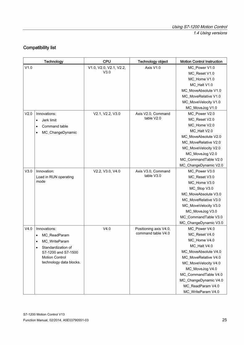
Compatibility list
Technology CPU Technology object Motion Control Instruction V1.0 V1.0, V2.0, V2.1, V2.2,
V3.0 Axis V1.0 MC_Power V1.0
MC_Reset V1.0 MC_Home V1.0 MC_Halt V1.0
MC_MoveAbsolute V1.0 MC_MoveRelative V1.0 MC_MoveVelocity V1.0
MC_MoveJog V1.0 V2.0 Innovations:
• Jerk limit • Command table • MC_ChangeDynamic
V2.1, V2.2, V3.0 Axis V2.0, Command table V2.0
MC_Power V2.0 MC_Reset V2.0 MC_Home V2.0 MC_Halt V2.0
MC_MoveAbsolute V2.0 MC_MoveRelative V2.0 MC_MoveVelocity V2.0
MC_MoveJog V2.0 MC_CommandTable V2.0 MC_ChangeDynamic V2.0
V3.0 Innovation: Load in RUN operating mode
V2.2, V3.0, V4.0 Axis V3.0, Command table V3.0
MC_Power V3.0 MC_Reset V3.0 MC_Home V3.0 MC_Stop V3.0
MC_MoveAbsolute V3.0 MC_MoveRelative V3.0 MC_MoveVelocity V3.0
MC_MoveJog V3.0 MC_CommandTable V3.0 MC_ChangeDynamic V3.0
V4.0 Innovations: • MC_ReadParam • MC_WriteParam • Standardization of
S7-1200 and S7-1500 Motion Control technology data blocks.
V4.0 Positioning axis V4.0, command table V4.0
MC_Power V4.0 MC_Reset V4.0 MC_Home V4.0 MC_Halt V4.0
MC_MoveAbsolute V4.0 MC_MoveRelative V4.0 MC_MoveVelocity V4.0
MC_MoveJog V4.0 MC_CommandTable V4.0 MC_ChangeDynamic V4.0
MC_ReadParam V4.0 MC_WriteParam V4.0
Using S7-1200 Motion Control 1.4 Using versions
S7-1200 Motion Control V13 26 Function Manual, 02/2014, A5E03790551-03
See also Changing a technology version (Page 26)
Compatibility list of tags (Page 27)
Status of limit switch (Page 30)
1.4.2 Changing a technology version Before you can access all the benefits of a new technology version, you may need to set / modify the technology version for existing projects.
Note Compatibility of the technology object tags
If you are switching from V1...3 and V4, please see the compatibility list (Page 27) if you are using tags of the technology object in your user program, monitoring tables, etc.
Setting/changing a technology version To set or change the technology version, follow these steps:
1. Open the programming editor (e.g., by opening the OB1).
2. In the "Instructions" task card, open the desired technology version in the "Technology > Motion Control > S7-1200 Motion Control" folder.
3. Save and compile the project. Pay attention to any error information that is displayed during compilation. Deal with the causes of the errors indicated.
4. Check the configuration of the technology objects.
5. If necessary, adapt the tag names in the following objects in line with the compatibility list.
● User program
● Monitoring tables
● Force tables
● HMI configuration
● Trace configuration
See also Overview of versions (Page 24)
Status of limit switch (Page 30)
Using S7-1200 Motion Control 1.4 Using versions
S7-1200 Motion Control V13 Function Manual, 02/2014, A5E03790551-03 27
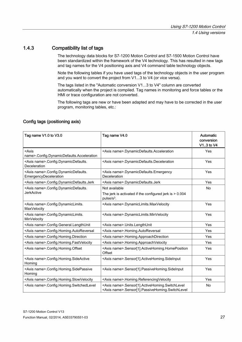
1.4.3 Compatibility list of tags The technology data blocks for S7-1200 Motion Control and S7-1500 Motion Control have been standardized within the framework of the V4 technology. This has resulted in new tags and tag names for the V4 positioning axis and V4 command table technology objects.
Note the following tables if you have used tags of the technology objects in the user program and you want to convert the project from V1...3 to V4 (or vice versa).
The tags listed in the "Automatic conversion V1...3 to V4" column are converted automatically when the project is compiled. Tag names in monitoring and force tables or the HMI or trace configuration are not converted.
The following tags are new or have been adapted and may have to be corrected in the user program, monitoring tables, etc.:
Config tags (positioning axis) Tag name V1.0 to V3.0 Tag name V4.0 Automatic
conversion V1..3 to V4
<Axis name>.Config.DynamicDefaults.Acceleration
<Axis name>.DynamicDefaults.Acceleration Yes
<Axis name>.Config.DynamicDefaults. Deceleration
<Axis name>.DynamicDefaults.Deceleration Yes
<Axis name>.Config.DynamicDefaults. EmergencyDeceleration
<Axis name>.DynamicDefaults.Emergency Deceleration
Yes
<Axis name>.Config.DynamicDefaults.Jerk <Axis name>.DynamicDefaults.Jerk Yes <Axis name>.Config.DynamicDefaults. JerkActive
Not available The jerk is activated if the configured jerk is > 0.004 pulse/s3.
No
<Axis name>.Config.DynamicLimits. MaxVelocity
<Axis name>.DynamicLimits.MaxVelocity Yes
<Axis name>.Config.DynamicLimits. MinVelocity
<Axis name>.DynamicLimits.MinVelocity Yes
<Axis name>.Config.General.LengthUnit <Axis name>.Units.LengthUnit Yes <Axis name>.Config.Homing.AutoReversal <Axis name>.Homing.AutoReversal Yes <Axis name>.Config.Homing.Direction <Axis name>.Homing.ApproachDirection Yes <Axis name>.Config.Homing.FastVelocity <Axis name>.Homing.ApproachVelocity Yes <Axis name>.Config.Homing.Offset <Axis name>.Sensor[1].ActiveHoming.HomePosition
Offset Yes
<Axis name>.Config.Homing.SideActive Homing
<Axis name>.Sensor[1].ActiveHoming.SideInput Yes
<Axis name>.Config.Homing.SidePassive Homing
<Axis name>.Sensor[1].PassiveHoming.SideInput Yes
<Axis name>.Config.Homing.SlowVelocity <Axis name>.Homing.ReferencingVelocity Yes <Axis name>.Config.Homing.SwitchedLevel <Axis name>.Sensor[1].ActiveHoming.SwitchLevel
<Axis name>.Sensor[1].PassiveHoming.SwitchLevel No

Using S7-1200 Motion Control 1.4 Using versions
S7-1200 Motion Control V13 28 Function Manual, 02/2014, A5E03790551-03
Tag name V1.0 to V3.0 Tag name V4.0 Automatic conversion V1..3 to V4
<Axis name>.Config.Mechanics.Inverse Direction
<Axis name>.Actor.InverseDirection Yes
<Axis name>.Config.Mechanics.LeadScrew <Axis name>.Mechanics.LeadScrew Yes <Axis name>.Config.Mechanics.PulsesPer DriveRevolution
<Axis name>.Actor.DriveParameter.PulsesPerDrive Revolution
Yes
<Axis name>.Config.PositionLimits_HW. Active
<Axis name>.PositionLimitsHW.Active Yes
<Axis name>.Config.PositionLimits_HW. MaxSwitchedLevel
<Axis name>.PositionLimitsHW.MaxSwitchLevel Yes
<Axis name>.Config.PositionLimits_HW. MinSwitchedLevel
<Axis name>.PositionLimitsHW.MinSwitchLevel Yes
<Axis name>.Config.PositionLimits_SW. Active
<Axis name>.PositionLimitsSW.Active Yes
<Axis name>.Config.PositionLimits_SW. MaxPosition
<Axis name>.PositionLimitsSW.MaxPosition Yes
<Axis name>.Config.PositionLimits_SW. MinPosition
<Axis name>.PositionLimitsSW.MinPosition Yes
Not available <Axis name>.Actor.DirectionMode No Not available <Axis name>.Actor.Type No Not available <Axis name>.Sensor[1].ActiveHoming.Mode No Not available <Axis name>.Sensor[1].PassiveHoming.Mode No
ErrorBits tags (positioning axis) Tag name V1.0 to V3.0 Tag name V4.0 Automatic
conversion V1..3 to V4
<Axis name>.ErrorBits.HwLimitMax <Axis name>.ErrorBits.HWLimit (Note the new status bits and the section Status of the limit switch (Page 30).)
No <Axis name>.ErrorBits.HwLimitMin
<Axis name>.ErrorBits.SwLimitMax Exceeded
<Axis name>.ErrorBits.SWLimit (Note the new status bits and the section Status of the limit switch (Page 30).)
No
<Axis name>.ErrorBits.SwLimitMaxReached <Axis name>.ErrorBits.SwLimitMinExceeded <Axis name>.ErrorBits.SwLimitMinReached Not available <Axis name>.ErrorBits.DirectionFault No
Using S7-1200 Motion Control 1.4 Using versions
S7-1200 Motion Control V13 Function Manual, 02/2014, A5E03790551-03 29
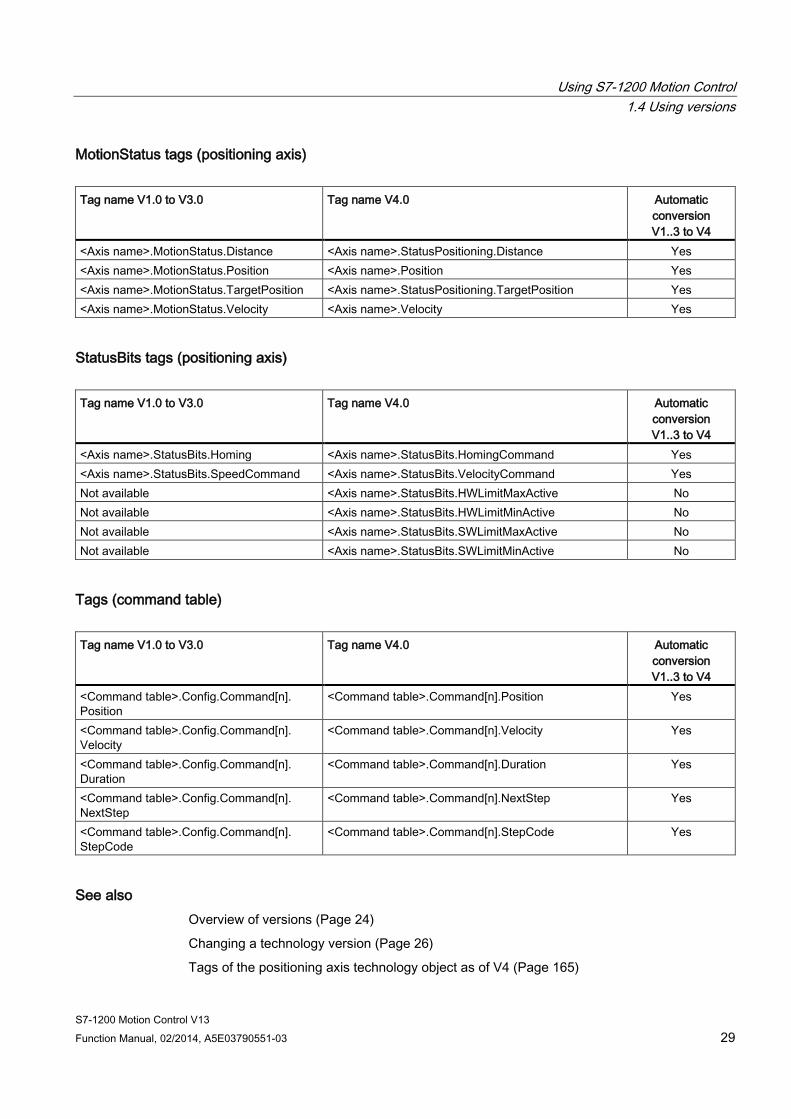
MotionStatus tags (positioning axis) Tag name V1.0 to V3.0 Tag name V4.0 Automatic
conversion V1..3 to V4
<Axis name>.MotionStatus.Distance <Axis name>.StatusPositioning.Distance Yes <Axis name>.MotionStatus.Position <Axis name>.Position Yes <Axis name>.MotionStatus.TargetPosition <Axis name>.StatusPositioning.TargetPosition Yes <Axis name>.MotionStatus.Velocity <Axis name>.Velocity Yes
StatusBits tags (positioning axis) Tag name V1.0 to V3.0 Tag name V4.0 Automatic
conversion V1..3 to V4
<Axis name>.StatusBits.Homing <Axis name>.StatusBits.HomingCommand Yes <Axis name>.StatusBits.SpeedCommand <Axis name>.StatusBits.VelocityCommand Yes Not available <Axis name>.StatusBits.HWLimitMaxActive No Not available <Axis name>.StatusBits.HWLimitMinActive No Not available <Axis name>.StatusBits.SWLimitMaxActive No Not available <Axis name>.StatusBits.SWLimitMinActive No
Tags (command table) Tag name V1.0 to V3.0 Tag name V4.0 Automatic
conversion V1..3 to V4
<Command table>.Config.Command[n]. Position
<Command table>.Command[n].Position Yes
<Command table>.Config.Command[n]. Velocity
<Command table>.Command[n].Velocity Yes
<Command table>.Config.Command[n]. Duration
<Command table>.Command[n].Duration Yes
<Command table>.Config.Command[n]. NextStep
<Command table>.Command[n].NextStep Yes
<Command table>.Config.Command[n]. StepCode
<Command table>.Command[n].StepCode Yes
See also Overview of versions (Page 24)
Changing a technology version (Page 26)
Tags of the positioning axis technology object as of V4 (Page 165)
Using S7-1200 Motion Control 1.4 Using versions
S7-1200 Motion Control V13 30 Function Manual, 02/2014, A5E03790551-03
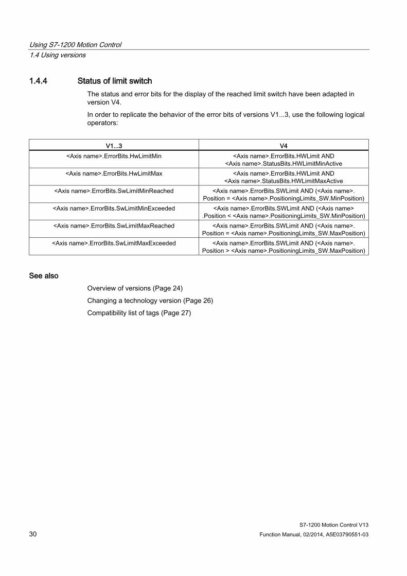
1.4.4 Status of limit switch The status and error bits for the display of the reached limit switch have been adapted in version V4.
In order to replicate the behavior of the error bits of versions V1...3, use the following logical operators:
V1...3 V4
<Axis name>.ErrorBits.HwLimitMin <Axis name>.ErrorBits.HWLimit AND <Axis name>.StatusBits.HWLimitMinActive
<Axis name>.ErrorBits.HwLimitMax <Axis name>.ErrorBits.HWLimit AND <Axis name>.StatusBits.HWLimitMaxActive
<Axis name>.ErrorBits.SwLimitMinReached <Axis name>.ErrorBits.SWLimit AND (<Axis name>. Position = <Axis name>.PositioningLimits_SW.MinPosition)
<Axis name>.ErrorBits.SwLimitMinExceeded <Axis name>.ErrorBits.SWLimit AND (<Axis name> .Position < <Axis name>.PositioningLimits_SW.MinPosition)
<Axis name>.ErrorBits.SwLimitMaxReached <Axis name>.ErrorBits.SWLimit AND (<Axis name>. Position = <Axis name>.PositioningLimits_SW.MaxPosition)
<Axis name>.ErrorBits.SwLimitMaxExceeded <Axis name>.ErrorBits.SWLimit AND (<Axis name>. Position > <Axis name>.PositioningLimits_SW.MaxPosition)
See also Overview of versions (Page 24)
Changing a technology version (Page 26)
Compatibility list of tags (Page 27)
Using S7-1200 Motion Control 1.5 Positioning axis technology object
S7-1200 Motion Control V13 Function Manual, 02/2014, A5E03790551-03 31
1.5 Positioning axis technology object
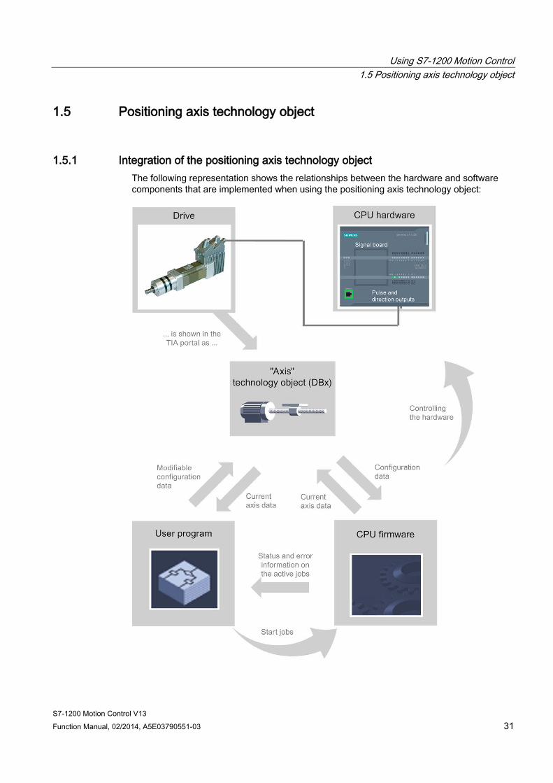
1.5.1 Integration of the positioning axis technology object The following representation shows the relationships between the hardware and software components that are implemented when using the positioning axis technology object:

Using S7-1200 Motion Control 1.5 Positioning axis technology object
S7-1200 Motion Control V13 32 Function Manual, 02/2014, A5E03790551-03
CPU hardware The physical drive is controlled and monitored by the CPU hardware.
Drive The drive represents the unit of power unit and motor. Stepper motors or servo motors with a pulse interface may be used.
Positioning axis technology object The physical drive including mechanics is mapped in the TIA Portal as a positioning axis technology object. To do this, configure the positioning axis technology object with the following parameters:
● Selection of the PTOs (Pulse Train Output) to be used and configuration of the drive interface
● Parameter for mechanics and gear transmission of the drive (or the machine or system)
● Parameter for position monitoring, for dynamic parameters and for homing
The configuration of the positioning axis technology object is saved in the technology object (data block). This data block also forms the interface between the user program and the CPU firmware. The current axis data is saved in the data block of the technology object at the runtime of the user program.
Using S7-1200 Motion Control 1.5 Positioning axis technology object
S7-1200 Motion Control V13 Function Manual, 02/2014, A5E03790551-03 33
User program You start Motion Control instructions jobs in the CPU firmware with the user program. The following jobs for controlling the axis are possible:
● Enable and disable axis
● Position axis absolutely
● Position axis relatively
● Move axis with velocity set point
● Run axis commands as motion sequence (technology as of V2)
● Moving axes in jog mode
● Stop axis
● Reference axis; set reference point
● Change dynamic settings of axis
● Continuously read motion data of the axis
● Write tag of axis
● Acknowledge error
You determine the command parameters with the input parameters of the Motion Control instructions and the axis configuration. The output parameters of the instruction give you up to date information about the status and any errors of the command.
Before starting a command for the axis, you must enable the axis with the Motion Control instruction "MC_Power".
You can read out configuration data and current axis data with the tags of the technology object. You can change individual, changeable tags of the technology object (e.g. the current acceleration) from the user program.
You can also change the dynamic settings of the axis with the Motion Control instruction "MC_ChangeDynamic" and write additional configuration data with "MC_WriteParam". You can read the current motion status of the axis with the Motion Control instruction "MC_ReadParam".
Using S7-1200 Motion Control 1.5 Positioning axis technology object
S7-1200 Motion Control V13 34 Function Manual, 02/2014, A5E03790551-03
CPU firmware The motion control jobs started in the user program are processed in the CPU firmware. When using the axis control table, Motion Control jobs are triggered by operating the axis control table. The CPU firmware performs the following jobs depending on the configuration:
● Calculate the exact motion profile for motion jobs and emergency stop situations
● Control the drive enable and the pulse and direction signal
● Monitor the drive and the hardware and software limit switches
● Up to date feedback of status and error information to the Motion Control instructions in the user program
● Writing of current axis data into the data block of the technology object
See also Tags of the positioning axis technology object as of V4 (Page 165)
CPU outputs relevant for motion control (technology version V4) (Page 12)
Relationship between the signal type and the direction of travel (Page 16)
Tools of the positioning axis technology object (Page 35)
Hardware and software limit switches (Page 20)
Homing (Page 22)
Using S7-1200 Motion Control 1.5 Positioning axis technology object
S7-1200 Motion Control V13 Function Manual, 02/2014, A5E03790551-03 35
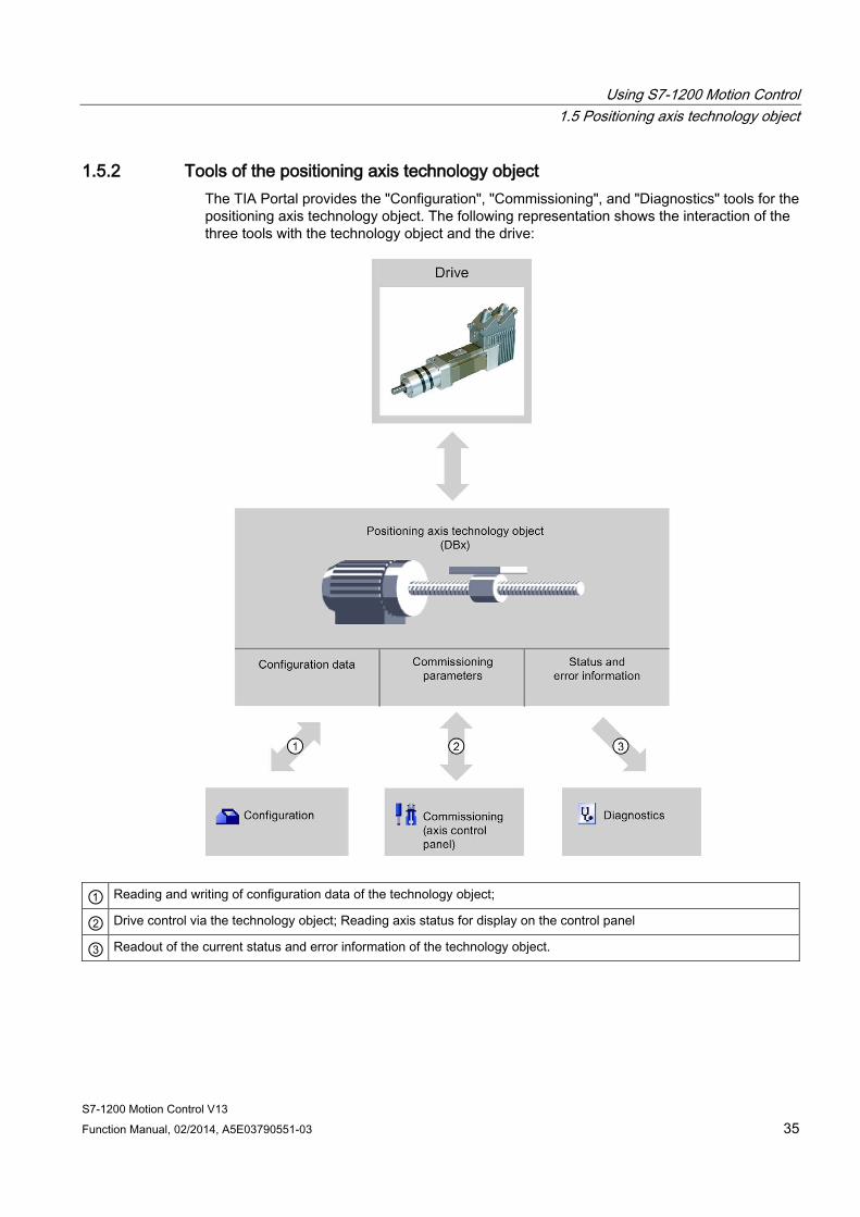
1.5.2 Tools of the positioning axis technology object The TIA Portal provides the "Configuration", "Commissioning", and "Diagnostics" tools for the positioning axis technology object. The following representation shows the interaction of the three tools with the technology object and the drive:
① Reading and writing of configuration data of the technology object;
② Drive control via the technology object; Reading axis status for display on the control panel
③ Readout of the current status and error information of the technology object.
Using S7-1200 Motion Control 1.5 Positioning axis technology object
S7-1200 Motion Control V13 36 Function Manual, 02/2014, A5E03790551-03
Configuration Use the "Configuration" tool to configure the following properties of the positioning axis technology object:
● Selection of the PTO to be used and configuration of the drive interface
● Properties of the mechanics and the transmission ratio of the drive (or machine or system)
● Properties for position monitoring, dynamics, and homing
Save the configuration in the data block of the technology object.
Commissioning Use the "Commissioning" tool to test the function of your axis without having to create a user program. When the tool is started, the axis control table will be displayed. The following commands are available on the axis control table:
● Enabling and disabling the axis
● Move axis in jog mode
● Position axis in absolute and relative terms
● Home axis
● Acknowledge errors
The dynamic values can be adjusted accordingly for the motion commands. The axis control table also shows the current axis status.
Diagnostics Use the "Diagnostics" tool to keep track of the current status and error information for the axis and drive.
See also CPU outputs relevant for motion control (technology version V4) (Page 12)
Relationship between the signal type and the direction of travel (Page 16)
Integration of the positioning axis technology object (Page 31)
Hardware and software limit switches (Page 20)
Homing (Page 22)
Configuring the positioning axis technology object (Page 38)
Commissioning the axis - Axis control panel (Page 88)
Axis - Diagnostics (Page 134)
Using S7-1200 Motion Control 1.5 Positioning axis technology object
S7-1200 Motion Control V13 Function Manual, 02/2014, A5E03790551-03 37
1.5.3 Adding a positioning axis technology object
Requirements A project with a CPU S7-1200 has been created.
Procedure To add a positioning axis technology object in the project tree, follow these steps:
1. Open the "CPU > Technology objects" folder in the project tree.
2. Double-click the "Add new object" command.
The "Add new object" dialog opens.
3. Select the "Motion Control" technology.
4. Open the "Motion Contro > S7-1200 Motion Control" folder.
5. Select the desired technology version in the "Version" column.
6. Select the "TO_PositioningAxis" object.
7. Enter the name of the axis in the "Name" input box.
8. To change the automatically assigned data block number, select the "Manual" option.
9. To display additional information about the technology object, click "Additional information".
10. Confirm your entry with "OK".
Result The new technology object is created and saved to the "Technology objects" folder in the project tree.
See also Guidelines on use of motion control (Page 23)

Using S7-1200 Motion Control 1.5 Positioning axis technology object
S7-1200 Motion Control V13 38 Function Manual, 02/2014, A5E03790551-03
1.5.4 Configuring the positioning axis technology object
1.5.4.1 Working with the configuration dialog You configure the properties of the technology object in the configuration window. Proceed as follows to open the configuration window of the technology object:
1. Open the group of the required technology object in the project tree.
2. Double-click the "Configuration" object.
The configuration is divided into the following categories:
● Basic parameters
The basic parameters contain all the parameters which must be configured for a functioning axis.
● Extended parameters
The advanced parameters include parameters to adapt to your drive or your plant.
Configuration window icons Icons in the area navigation of the configuration show additional details about the status of the configuration:
The configuration contains default values and is complete.
The configuration contains only default values. With these default values you can use the technology object without additional changes.
The configuration contains values set by the user and is complete. All input boxess of the configuration contain valid values and at least one preset value has changed.
The configuration is incomplete or incorrect At least one input box or drop-down list contains an invalid value. The corresponding box or the drop-down list is displayed on a red background. Click the roll-out error message to indicate the cause of error.
The configuration is valid but contains warnings For example, only one hardware limit switch is configured. Depending on the plant, the lacking configuration of a hardware limit switch may result in a hazard. The corresponding box or the drop-down list is displayed on a yellow background.
See also Guidelines on use of motion control (Page 23)
Basic parameters (Page 40)
Extended parameters (Page 43)

Using S7-1200 Motion Control 1.5 Positioning axis technology object
S7-1200 Motion Control V13 Function Manual, 02/2014, A5E03790551-03 39
1.5.4.2 Compare values The "Compare values" function provides the following options:
● Comparison of configured start values of the project with the start values in the CPU and the actual values
● Direct editing of actual values and the start values of the project
● Immediate detection and display of input errors with suggested corrections
● Backup of actual values in the project
● Transfer of start values of the project to the CPU as actual values
Icons and operator controls The following icons and operator controls are available:
Icon Function
Start value in CPU matches the configured Start value in the project
Start value in CPU does not match the configured Start value in the project
The comparison of the Start value in CPU with the configured Start value in the project cannot be performed
Backs up the actual values in the project
Transfers updated start values in the project to the CPU (initialize setting values)
Opens the "Compare values" dialog
Using S7-1200 Motion Control 1.5 Positioning axis technology object
S7-1200 Motion Control V13 40 Function Manual, 02/2014, A5E03790551-03
1.5.4.3 Basic parameters
Configuration - General (positioning axis technology object as of V4) Configure the basic properties of the positioning axis technology object in the "General" configuration window.
Axis name Define the name of the axis or the name of the positioning axis technology object in this box. The technology object is listed under this name in the project navigation.
Hardware interface The pulses are output to the power unit of the drive by fixed assigned digital outputs.
In CPUs with relay outputs, the pulse signal cannot be output on these outputs because the relays do not support the necessary switching frequencies. A signal board with digital outputs must be used to enable you to work with the PTO (Pulse Train Output) on these CPUs.
Note
The PTO requires the functionality of a fast counter (HSC). An internal HSC is used for this, the count of which cannot be evaluated.
Selecting the pulse generator In the drop-down list, select the PTO (Pulse Train Output) which is to provide the pulses for controlling the stepper motors or servo motors with pulse interface. If the pulse generators and high-speed counters are not used elsewhere in the device configuration, the hardware interface can be configured automatically. In this case, the PTO selected in the drop-down list is displayed with a white background.
"Device configuration" button This button takes you to the settings for the pulse options in the device configuration of the CPU.

Using S7-1200 Motion Control 1.5 Positioning axis technology object
S7-1200 Motion Control V13 Function Manual, 02/2014, A5E03790551-03 41
Signal type Select the desired signal type in the drop-down list. The following signal types are available:
● PTO (pulse A and direction B)
A pulse output and a direction output are used for controlling the stepper motor.
● PTO (count up A, count down B)
One pulse output each for motion in positive direction and negative direction is used for controlling the stepper motor.
● PTO (A/B phase offset) Both pulse outputs for Phase A and for Phase B run at the same frequency. The period of the pulse outputs is evaluated at the drive end as a step. The phase offset between Phase A and Phase B determines the direction of the motion.
● PTO (A/B phase offset - quadruple)
Both pulse outputs for Phase A and for Phase B run at the same frequency. All positive edges and all negative edges of Phase A and Phase B are evaluated as a step at the drive end. The phase offset between Phase A and Phase B determines the direction of the motion.
Pulse output (signal type "PTO (pulse A and direction B)") Select the desired output for the pulse output in this box.
You can select the output using a symbolic address or assign an absolute address.
Activate direction output (signal type "PTO (pulse A and direction B)") You can deactivate and activate the direction output in "pulse and direction" mode. This option enables you to limit the motion direction.
Direction output (signal type "PTO (pulse A and direction B)") Select the desired output for the direction output in this box.
You can select the output using a symbolic address or assign an absolute address.
Pulse output up (signal type "PTO (count up A, count down B)") Select the desired pulse output for motions in positive direction in this box.
You can select the output using a symbolic address or assign an absolute address.
Pulse output down (signal type "PTO (count up A, count down B)") Select the desired pulse output for motions in negative direction in this box.
You can select the output using a symbolic address or assign an absolute address.

Using S7-1200 Motion Control 1.5 Positioning axis technology object
S7-1200 Motion Control V13 42 Function Manual, 02/2014, A5E03790551-03
Phase A (signal types "PTO (A/B phase offset)" and "PTO (A/B phase offset - quadruple)") Select the desired pulse output for Phase A signals in this box.
You can select the output using a symbolic address or assign an absolute address.
Phase B (signal types "PTO (A/B phase offset)" and "PTO (A/B phase offset - quadruple)") Select the desired pulse output for Phase B signals in this box.
You can select the output using a symbolic address or assign an absolute address.
User unit Select the desired unit for the dimension system of the axis in the dropdown list. The selected unit is used for further configuration of the positioning axis technology object and for displaying the current axis data.
The values at the input parameters (Position, Distance, Velocity, ...) of the Motion Control instructions also refer to this unit.
Note
Later changing of the dimension system may not be converted correctly in all the configuration windows of the technology object. In this case check the configuration of all axis parameters.
The values of the input parameters of the Motion Control instructions may have to be adapted to the new unit of measurement in the user program.
See also CPU outputs relevant for motion control (technology version V4) (Page 12)
Relationship between the signal type and the direction of travel (Page 16)
Configuration - General ("Axis" technology object V1...3) (Page 193)
Using S7-1200 Motion Control 1.5 Positioning axis technology object
S7-1200 Motion Control V13 Function Manual, 02/2014, A5E03790551-03 43
1.5.4.4 Extended parameters
Configuration - Drive interface Configure the output for drive enable and the input for the "Drive ready" feedback signal of the drive in the "Drive signals" configuration window.
Drive enable is controlled by Motion Control instruction "MC_Power" and enables power to the drive. The signal is provided to the drive via the output to be configured.
The drive signals "Drive ready" to the CPU if it is ready to start executing travel after receipt of drive enable. The "Drive ready" signal is reported back to the CPU via the input to be configured.
If the drive does not have any interfaces of this type, you will not have to configure the parameters. In this case, select the value TRUE for the ready input.
See also Configuration - Mechanics (Page 43)
Position limits (Page 45)
Dynamics (Page 50)
Homing (positioning axis technology object as of V2) (Page 58)
Configuration - Mechanics Configure the mechanical properties of the drive in the "Mechanics" configuration window.
Increments per motor revolution Configure the number of pulses required for one revolution of the motor in this box.
Limits (independent of the selected unit of measurement):
● 0 < Pulse per motor revolution ≤ 2147483647
Distance per revolution In this box, configure the load distance per motor revolution covered by the mechanical system of your unit.
Limits (independent of the selected unit of measurement):
● 0.0 < Distance per revolution ≤ 1.0e12
Using S7-1200 Motion Control 1.5 Positioning axis technology object
S7-1200 Motion Control V13 44 Function Manual, 02/2014, A5E03790551-03
Permitted direction of rotation (technology version as of V4) Configure this box to determine whether the mechanics of your system are to move in both directions or only in the positive or negative direction.
If you have not activated the direction output of the pulse generator in the "PTO (pulse A and direction B)" mode, the selection is limited to the positive or negative direction.
Invert direction You can use the "Invert direction" check box to adapt the control system to the direction logic of the drive.
The direction logic is inverted according to the selected mode of the pulse generator:
● PTO (pulse A and direction B)
– 0 V at direction output ⇒ positive direction of rotation
– 5 V/24 V at direction output ⇒ negative direction of rotation
The specified voltage depends on the hardware used. The indicated values do not apply to the differential outputs of CPU 1217.
● PTO (count up A, count down B)
The outputs "Pulse output down" and "Pulse output up" are swapped.
● PTO (A/B phase offset)
The "Phase A" and "Phase B" outputs are swapped.
● "PTO (A/B phase offset - quadruple)
The "Phase A" and "Phase B" outputs are swapped.
See also Configuration - Drive interface (Page 43)
Position limits (Page 45)
Dynamics (Page 50)
Homing (positioning axis technology object as of V2) (Page 58)
Relationship between the signal type and the direction of travel (Page 16)

Using S7-1200 Motion Control 1.5 Positioning axis technology object
S7-1200 Motion Control V13 Function Manual, 02/2014, A5E03790551-03 45
Position limits
Requirements for hardware limit switches Use only hardware limit switches that remain permanently switched after being approached. This switching status may only be revoked after a return to the valid travel range.
See also Configuration - Position limits (Page 45)
Behavior of axis when position limits is tripped (Page 47)
Changing the position limits configuration in the user program (Page 49)
Configuration - Position limits Configure the hardware and software limit switches of the axis in the "Position limits" configuration window.
Enable hardware limit switch Activate the function of the low and upper hardware limit switch with this check box. The hardware limit switches can be used for purposes of direction reversal during a homing procedure. For details, refer to the configuration description for homing.
Lower / upper HW limit switch input Select the digital input for the low or upper hardware limit switch from the drop-down list. The input must be interrupt-capable. The digital onboard CPU inputs and the digital inputs of a plugged signal board can be selected as inputs for the HW limit switches.
Note
The digital inputs are set to a filter time of 6.4 ms by default. If these are used as hardware limit switches, undesired decelerations may occur. If this occurs, reduce the filter time for the relevant digital inputs.
The filter time can be set under "Input filter" in the device configuration of the digital inputs.
Using S7-1200 Motion Control 1.5 Positioning axis technology object
S7-1200 Motion Control V13 46 Function Manual, 02/2014, A5E03790551-03
Active level In the drop-down list, select the signal level available at the CPU when the hardware limit switch is approached.
● "Lower level" selected
0 V (FALSE) at CPU input corresponds to hardware limit switch approached
● "High level" selected
5 V / 24 V (TRUE) at the CPU input = hardware limit switch approached (the actual voltage depends on the hardware used)
Enable software limit switch Activate the function of the low and upper software limit switch with this check box.
Note
The enabled software limit switch only affects a homed axis.
High and lower software limit switch Enter the position value of the low and upper software limit switch in these boxes.
Limits (independent of the selected unit of measurement):
● -1.0e12 ≤ lower software limit switch ≤ 1.0e12
● -1.0e12 ≤ upper software limit switch ≤ 1.0e12
The value of the upper software limit switch must be greater than or equal to the value of the lower software limit switch.
See also Requirements for hardware limit switches (Page 45)
Behavior of axis when position limits is tripped (Page 47)
Changing the position limits configuration in the user program (Page 49)
Configuration - Homing - Active (Page 59)
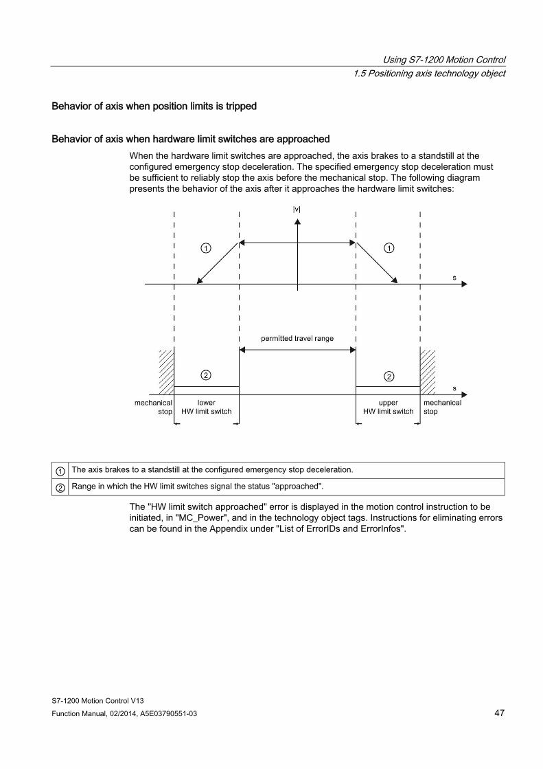
Using S7-1200 Motion Control 1.5 Positioning axis technology object
S7-1200 Motion Control V13 Function Manual, 02/2014, A5E03790551-03 47
Behavior of axis when position limits is tripped
Behavior of axis when hardware limit switches are approached When the hardware limit switches are approached, the axis brakes to a standstill at the configured emergency stop deceleration. The specified emergency stop deceleration must be sufficient to reliably stop the axis before the mechanical stop. The following diagram presents the behavior of the axis after it approaches the hardware limit switches:
① The axis brakes to a standstill at the configured emergency stop deceleration.
② Range in which the HW limit switches signal the status "approached".
The "HW limit switch approached" error is displayed in the motion control instruction to be initiated, in "MC_Power", and in the technology object tags. Instructions for eliminating errors can be found in the Appendix under "List of ErrorIDs and ErrorInfos".
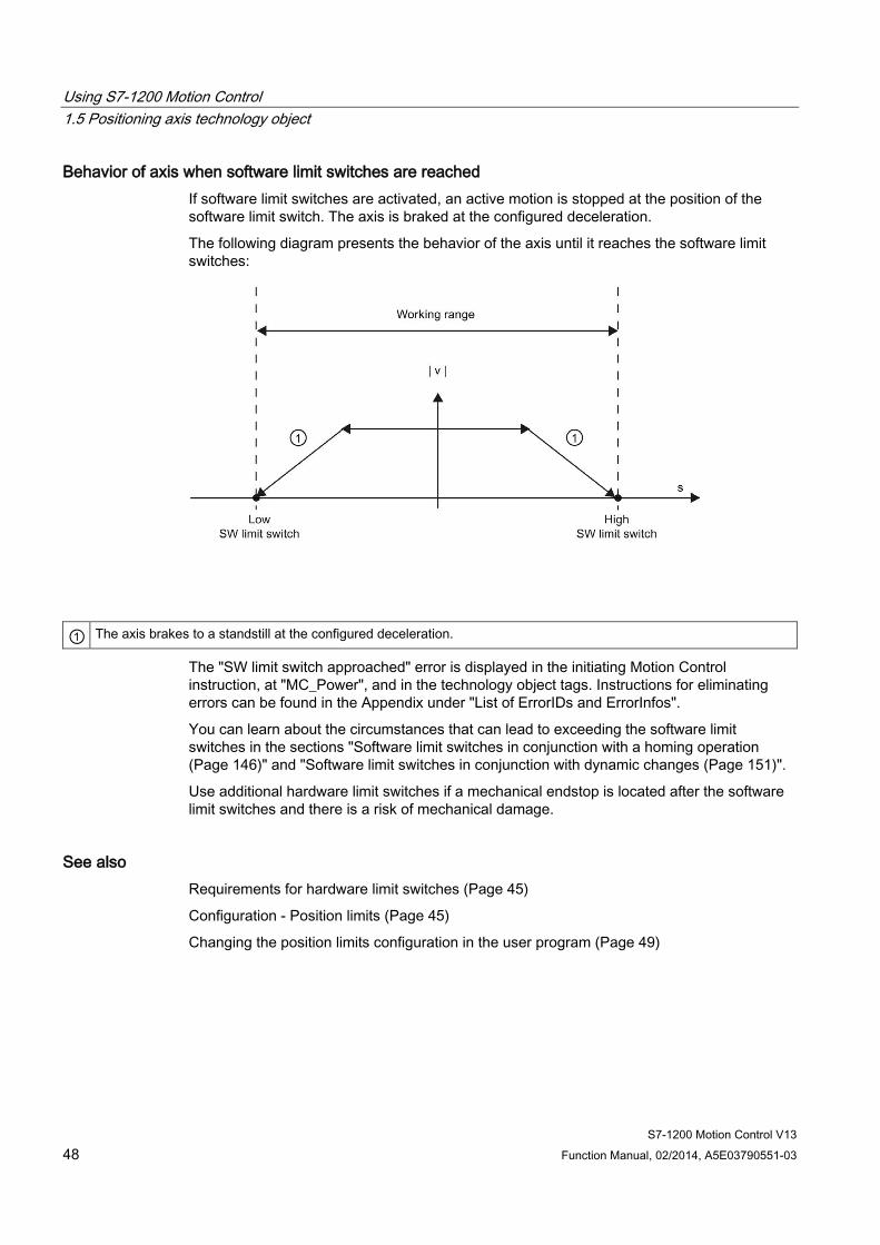
Using S7-1200 Motion Control 1.5 Positioning axis technology object
S7-1200 Motion Control V13 48 Function Manual, 02/2014, A5E03790551-03
Behavior of axis when software limit switches are reached If software limit switches are activated, an active motion is stopped at the position of the software limit switch. The axis is braked at the configured deceleration.
The following diagram presents the behavior of the axis until it reaches the software limit switches:
① The axis brakes to a standstill at the configured deceleration.
The "SW limit switch approached" error is displayed in the initiating Motion Control instruction, at "MC_Power", and in the technology object tags. Instructions for eliminating errors can be found in the Appendix under "List of ErrorIDs and ErrorInfos".
You can learn about the circumstances that can lead to exceeding the software limit switches in the sections "Software limit switches in conjunction with a homing operation (Page 146)" and "Software limit switches in conjunction with dynamic changes (Page 151)".
Use additional hardware limit switches if a mechanical endstop is located after the software limit switches and there is a risk of mechanical damage.
See also Requirements for hardware limit switches (Page 45)
Configuration - Position limits (Page 45)
Changing the position limits configuration in the user program (Page 49)

Using S7-1200 Motion Control 1.5 Positioning axis technology object
S7-1200 Motion Control V13 Function Manual, 02/2014, A5E03790551-03 49
Changing the position limits configuration in the user program You can change the following configuration parameters during runtime of the user program in the CPU:
Hardware limit switches You can also activate and deactivate the hardware limit switches during runtime of the user program. Use the following technology object tag for this purpose:
● <Axis name>.PositionLimitsHW.Active
Refer to the description of the technology object tags (Page 165) in the appendix for information on when changes to the configuration parameter take effect.
Software limit switches You can also activate and deactivate the software limit switches and change their position values during runtime of the user program. Use the following technology object tags for this purpose:
● <Axis name>.PositionLimitsSW.Active
for activating and deactivating the software limit switches
● <Axis name>.PositionLimitsSW.MinPosition
for changing the position of the lower software limit switch
● <Axis name>.PositionLimitsSW.MaxPosition
for changing the position of the upper software limit switch
Refer to the description of technology object tags in the appendix for information on when changes to the configuration parameters take effect.
See also Compatibility list of tags (Page 27)
MC_ChangeDynamic: Change dynamic settings of axis V4 (Page 275)
Requirements for hardware limit switches (Page 45)
Configuration - Position limits (Page 45)
Behavior of axis when position limits is tripped (Page 47)
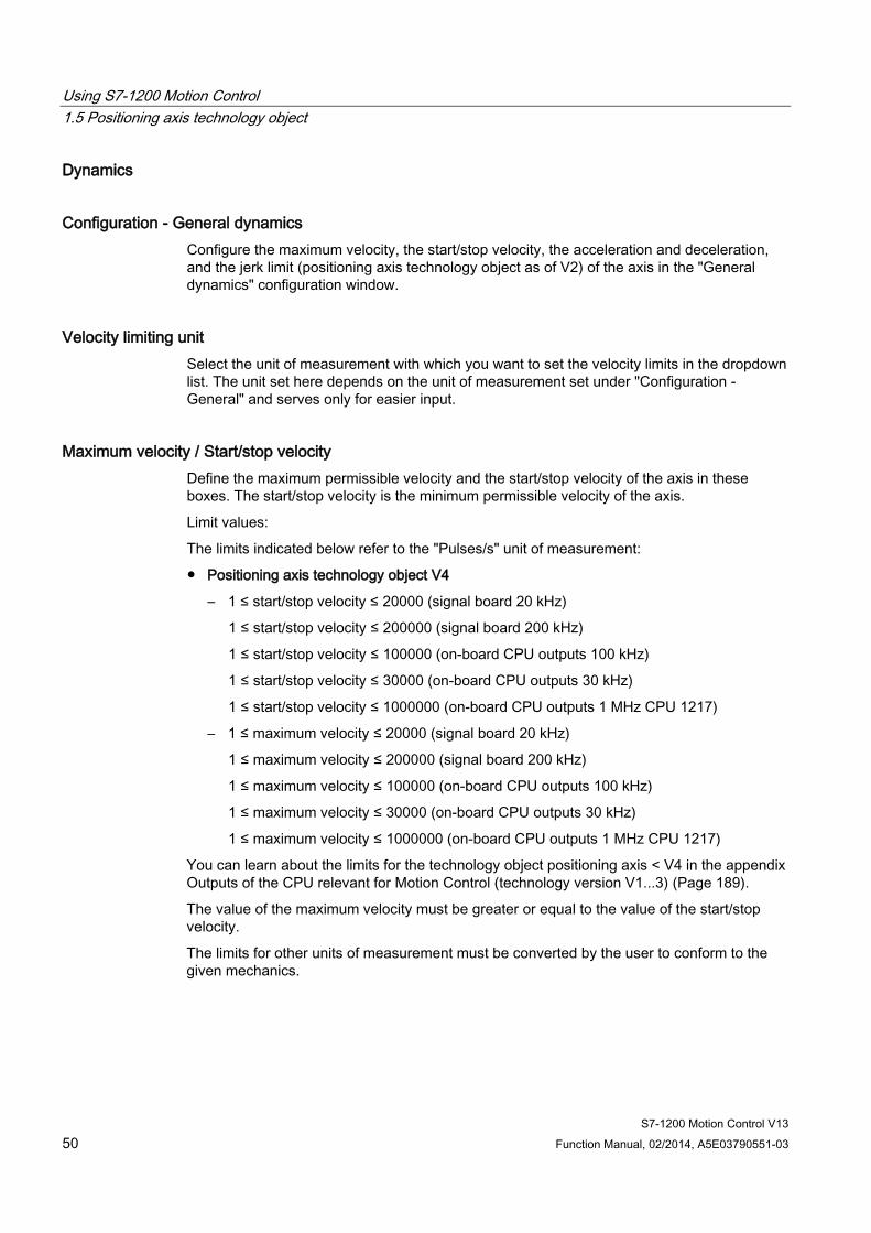
Using S7-1200 Motion Control 1.5 Positioning axis technology object
S7-1200 Motion Control V13 50 Function Manual, 02/2014, A5E03790551-03
Dynamics
Configuration - General dynamics Configure the maximum velocity, the start/stop velocity, the acceleration and deceleration, and the jerk limit (positioning axis technology object as of V2) of the axis in the "General dynamics" configuration window.
Velocity limiting unit Select the unit of measurement with which you want to set the velocity limits in the dropdown list. The unit set here depends on the unit of measurement set under "Configuration - General" and serves only for easier input.
Maximum velocity / Start/stop velocity Define the maximum permissible velocity and the start/stop velocity of the axis in these boxes. The start/stop velocity is the minimum permissible velocity of the axis.
Limit values:
The limits indicated below refer to the "Pulses/s" unit of measurement:
● Positioning axis technology object V4
– 1 ≤ start/stop velocity ≤ 20000 (signal board 20 kHz)
1 ≤ start/stop velocity ≤ 200000 (signal board 200 kHz)
1 ≤ start/stop velocity ≤ 100000 (on-board CPU outputs 100 kHz)
1 ≤ start/stop velocity ≤ 30000 (on-board CPU outputs 30 kHz)
1 ≤ start/stop velocity ≤ 1000000 (on-board CPU outputs 1 MHz CPU 1217)
– 1 ≤ maximum velocity ≤ 20000 (signal board 20 kHz)
1 ≤ maximum velocity ≤ 200000 (signal board 200 kHz)
1 ≤ maximum velocity ≤ 100000 (on-board CPU outputs 100 kHz)
1 ≤ maximum velocity ≤ 30000 (on-board CPU outputs 30 kHz)
1 ≤ maximum velocity ≤ 1000000 (on-board CPU outputs 1 MHz CPU 1217)
You can learn about the limits for the technology object positioning axis < V4 in the appendix Outputs of the CPU relevant for Motion Control (technology version V1...3) (Page 189).
The value of the maximum velocity must be greater or equal to the value of the start/stop velocity.
The limits for other units of measurement must be converted by the user to conform to the given mechanics.
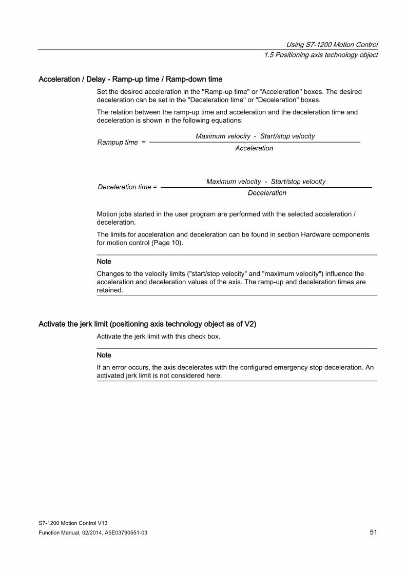
Using S7-1200 Motion Control 1.5 Positioning axis technology object
S7-1200 Motion Control V13 Function Manual, 02/2014, A5E03790551-03 51
Acceleration / Delay - Ramp-up time / Ramp-down time Set the desired acceleration in the "Ramp-up time" or "Acceleration" boxes. The desired deceleration can be set in the "Deceleration time" or "Deceleration" boxes.
The relation between the ramp-up time and acceleration and the deceleration time and deceleration is shown in the following equations:
Motion jobs started in the user program are performed with the selected acceleration / deceleration.
The limits for acceleration and deceleration can be found in section Hardware components for motion control (Page 10).
Note
Changes to the velocity limits ("start/stop velocity" and "maximum velocity") influence the acceleration and deceleration values of the axis. The ramp-up and deceleration times are retained.
Activate the jerk limit (positioning axis technology object as of V2) Activate the jerk limit with this check box.
Note
If an error occurs, the axis decelerates with the configured emergency stop deceleration. An activated jerk limit is not considered here.
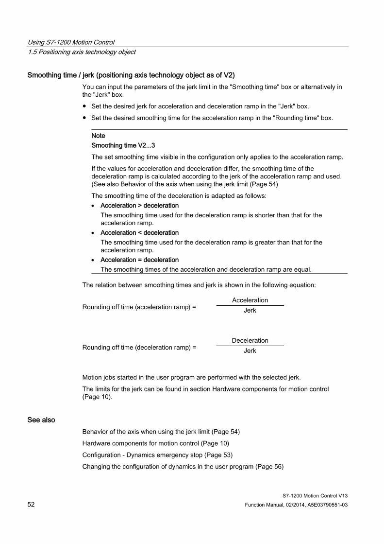
Using S7-1200 Motion Control 1.5 Positioning axis technology object
S7-1200 Motion Control V13 52 Function Manual, 02/2014, A5E03790551-03
Smoothing time / jerk (positioning axis technology object as of V2) You can input the parameters of the jerk limit in the "Smoothing time" box or alternatively in the "Jerk" box.
● Set the desired jerk for acceleration and deceleration ramp in the "Jerk" box.
● Set the desired smoothing time for the acceleration ramp in the "Rounding time" box.
Note
Smoothing time V2...3
The set smoothing time visible in the configuration only applies to the acceleration ramp.
If the values for acceleration and deceleration differ, the smoothing time of the deceleration ramp is calculated according to the jerk of the acceleration ramp and used. (See also Behavior of the axis when using the jerk limit (Page 54)
The smoothing time of the deceleration is adapted as follows: • Acceleration > deceleration
The smoothing time used for the deceleration ramp is shorter than that for the acceleration ramp.
• Acceleration < deceleration The smoothing time used for the deceleration ramp is greater than that for the acceleration ramp.
• Acceleration = deceleration The smoothing times of the acceleration and deceleration ramp are equal.
The relation between smoothing times and jerk is shown in the following equation:
Motion jobs started in the user program are performed with the selected jerk.
The limits for the jerk can be found in section Hardware components for motion control (Page 10).
See also Behavior of the axis when using the jerk limit (Page 54)
Hardware components for motion control (Page 10)
Configuration - Dynamics emergency stop (Page 53)
Changing the configuration of dynamics in the user program (Page 56)

Using S7-1200 Motion Control 1.5 Positioning axis technology object
S7-1200 Motion Control V13 Function Manual, 02/2014, A5E03790551-03 53
Configuration - Dynamics emergency stop Configure the emergency stop deceleration of the axis in the "Dynamics emergency stop" configuration window. In the event of an error, and when disabling the axis, the axis is brought to a standstill with this deceleration using the Motion Control instruction "MC_Power" (input parameter StopMode = 0 or 2).
Velocity limits The velocity values configured in the "General dynamics" configuration window are once again displayed in this information area.
Deceleration Set the deceleration value for emergency stop in the "Emergency stop deceleration" or "Emergency stop ramp-down time" field.
The relation between emergency stop deceleration time and emergency stop deceleration is shown in the following equation:
The specified emergency stop deceleration must be sufficient to bring the axis to a standstill in a timely manner in the event of an emergency (for example, when the hardware limit switch is approached prior to reaching the mechanical endstop).
The configured maximum velocity of the axis must be used as a basis for selecting the emergency stop deceleration.
Limit values:
The limits indicated below refer to the "Pulses/s2" unit of measurement:
● As of CPU firmware V3
0.005 ≤ emergency stop deceleration ≤ 9.5E9
● CPU Firmware V1...2
0.28 ≤ emergency stop deceleration ≤ 9.5E9
The limits for other units of measurement must be converted to conform to the given mechanics.
See also Configuration - General dynamics (Page 50)
Changing the configuration of dynamics in the user program (Page 56)
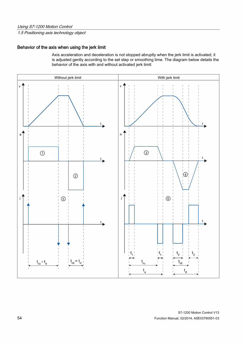
Using S7-1200 Motion Control 1.5 Positioning axis technology object
S7-1200 Motion Control V13 54 Function Manual, 02/2014, A5E03790551-03
Behavior of the axis when using the jerk limit Axis acceleration and deceleration is not stopped abruptly when the jerk limit is activated; it is adjusted gently according to the set step or smoothing time. The diagram below details the behavior of the axis with and without activated jerk limit:
Without jerk limit With jerk limit
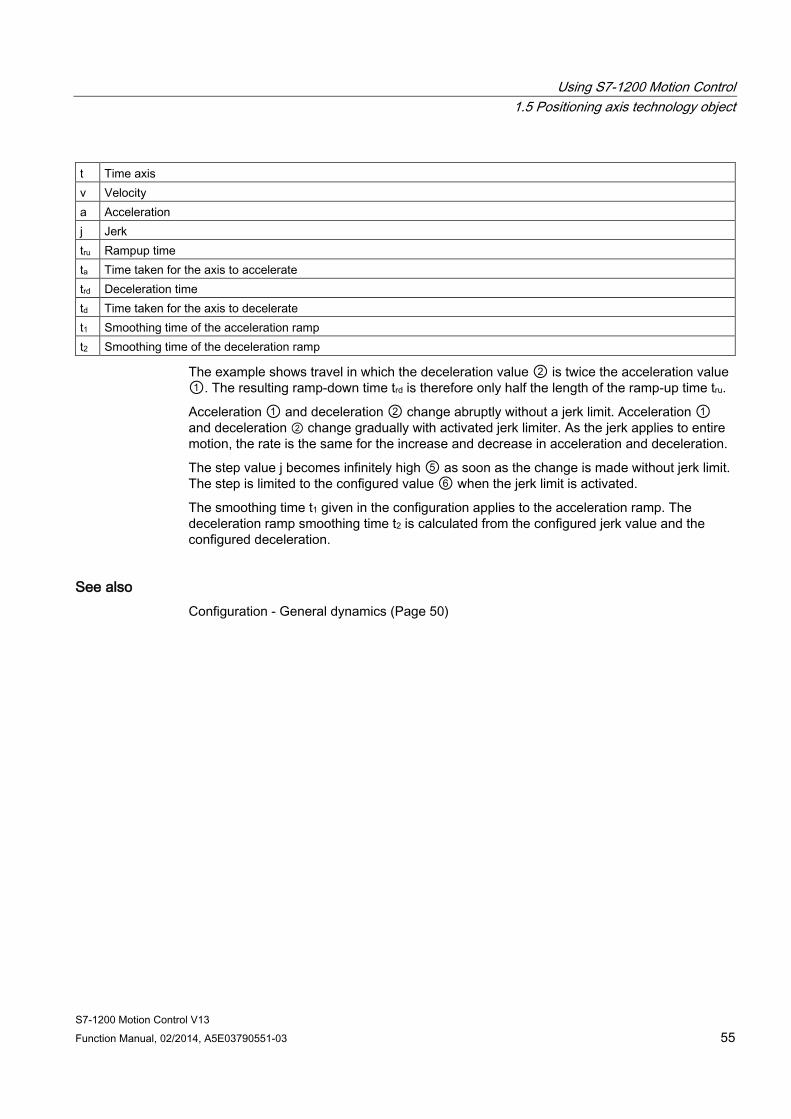
Using S7-1200 Motion Control 1.5 Positioning axis technology object
S7-1200 Motion Control V13 Function Manual, 02/2014, A5E03790551-03 55
t Time axis v Velocity a Acceleration j Jerk tru Rampup time ta Time taken for the axis to accelerate trd Deceleration time td Time taken for the axis to decelerate t1 Smoothing time of the acceleration ramp t2 Smoothing time of the deceleration ramp
The example shows travel in which the deceleration value ② is twice the acceleration value ①. The resulting ramp-down time trd is therefore only half the length of the ramp-up time tru.
Acceleration ① and deceleration ② change abruptly without a jerk limit. Acceleration ① and deceleration ② change gradually with activated jerk limiter. As the jerk applies to entire motion, the rate is the same for the increase and decrease in acceleration and deceleration.
The step value j becomes infinitely high ⑤ as soon as the change is made without jerk limit. The step is limited to the configured value ⑥ when the jerk limit is activated.
The smoothing time t1 given in the configuration applies to the acceleration ramp. The deceleration ramp smoothing time t2 is calculated from the configured jerk value and the configured deceleration.
See also Configuration - General dynamics (Page 50)
Using S7-1200 Motion Control 1.5 Positioning axis technology object
S7-1200 Motion Control V13 56 Function Manual, 02/2014, A5E03790551-03
Changing the configuration of dynamics in the user program You can change the following configuration parameters during runtime of the user program in the CPU:
Acceleration and deceleration You can also change the values for acceleration and deceleration during runtime of the user program. Use the following technology object tags for this purpose:
● <Axis name>.DynamicDefaults.Acceleration
for changing acceleration
● <Axis name>.DynamicDefaults.Deceleration
for changing deceleration
Refer to the description of the technology object tags (Page 165) in the appendix for information on when changes to the configuration parameters take effect.
Emergency stop deceleration You can also change the value for the emergency stop deceleration during runtime of the user program. Use the following technology object tag for this purpose:
● <Axis name>.DynamicDefaults.EmergencyDeceleration
Refer to the description of the technology object tags in the appendix for information on when changes to the configuration parameter take effect.
Note
After changes to this parameter, it may be necessary to adapt the positions of the hardware limit switches and other safety-relevant settings.
Using S7-1200 Motion Control 1.5 Positioning axis technology object
S7-1200 Motion Control V13 Function Manual, 02/2014, A5E03790551-03 57
Jerk limit You can also activate and deactivate the jerk limit at runtime of the user program and change the value for the jerk. To do this, use the technology object tag <Axis name>.DynamicDefaults.Jerk.
If you enter a value > 0.004 pulse/s3 for the jerk, the jerk limit is activated with the specified value.
If you enter a value = 0.0 for the jerk, the jerk limit is deactivated.
Refer to the description of the technology object tags in the appendix for information on when changes to the configuration parameter take effect.
See also Changing configuration of dynamic values in user program ("Axis" technology object V1...3) (Page 195)
Compatibility list of tags (Page 27)
MC_ChangeDynamic: Change dynamic settings of axis V4 (Page 275)
Configuration - General dynamics (Page 50)
Configuration - Dynamics emergency stop (Page 53)
Using S7-1200 Motion Control 1.5 Positioning axis technology object
S7-1200 Motion Control V13 58 Function Manual, 02/2014, A5E03790551-03
Homing (positioning axis technology object as of V2)
Configuration - Homing - Passive Configure the necessary parameters for passive homing in the "Homing - Passive" configuration window.
The movement for passive homing must be triggered by the user (e.g. using an axis motion command). Passive homing is started using Motion Control instruction "MC_Home" with input parameter "Mode" = 2.
Homing switch input Select the digital input for the homing switch from the drop-down list. The input must be interrupt-capable. The on-board CPU inputs and the inputs of an inserted signal board can be selected as inputs for the homing switch.
Note
The digital inputs are set to a filter time of 6.4 ms by default.
When the digital inputs are used as a homing switch, this can result in undesired decelerations and thus inaccuracies. Depending on the homing velocity and extent of the homing switch, the home position may not be detected. The filter time can be set under "Input filter" in the device configuration of the digital inputs.
The specified filter time must be less than the duration of the input signal at the homing switch.
Active level In the drop-list, select the level of the homing switch that is to be used for homing.
Side of the homing switch This is where you select whether the axis is to be homed on the low or high end of the homing switch.
Home position The position configured in the Motion Control instruction "MC_Home" is used as the home position.
Note
If passive homing is carried out without an axis motion command (axis at a standstill), homing will be executed upon the next rising or falling edge at the homing switch.
Using S7-1200 Motion Control 1.5 Positioning axis technology object
S7-1200 Motion Control V13 Function Manual, 02/2014, A5E03790551-03 59
Configuration - Homing - Active Configure the necessary parameters for active homing in the "Active homing" configuration window. Active homing is started using Motion Control instruction "MC_Home" with input parameter "Mode" = 3.
Homing switch input Select the digital input for the homing switch from the drop-down list. The input must be interrupt-capable. The on-board CPU inputs and the inputs of an inserted signal board can be selected as inputs for the homing switch.
Note
The digital inputs are set to a filter time of 6.4 ms by default.
When the digital inputs are used as a homing switch, this can result in undesired decelerations and thus inaccuracies. Depending on the homing velocity and extent of the homing switch, the home position may not be detected. The filter time can be set under "Input filter" in the device configuration of the digital inputs.
The specified filter time must be less than the duration of the input signal at the homing switch.
Active level In the drop-list, select the level of the homing switch that is to be used for homing.
Allowing direction reversal at the hardware limit switch Activate the check box to use the hardware limit switch as a reversing cam for the homing procedure. The hardware limit switches must be enabled for the reversal of direction (at least the hardware limit switch in the direction of approach must be configured).
If the hardware limit switch is reached during active homing, the axis brakes at the configured deceleration (not with the emergency stop deceleration) and reverses direction. The homing switch is then sensed in reverse direction.
If the direction reversal is not active and the axis reaches the hardware limit switch during active homing, the homing procedure is aborted with an error and the axis is braked at the emergency stop deceleration.
Note
If possible, use one of the following measures to ensure that the machine does not travel to a mechanical endstop in the event of a direction reversal: • Keep the approach velocity low. • Increase the configured acceleration/deceleration. • Increase the distance between the hardware limit switch and the mechanical endstop.
Using S7-1200 Motion Control 1.5 Positioning axis technology object
S7-1200 Motion Control V13 60 Function Manual, 02/2014, A5E03790551-03
Approach/homing direction With the direction selection, you determine the approach direction used during active homing to search for the homing switch, as well as the homing direction. The homing direction specifies the travel direction the axis uses to approach the configured end of the homing switch to carry out the homing operation.
Side of the homing switch This is where you select whether the axis is to be homed on the low or high end of the homing switch.
Approach velocity In this box, specify the velocity at which the homing switch is to be searched for during the homing procedure.
Limits (independent of the selected unit of measurement):
● Start/stop velocity ≤ approach velocity ≤ maximum velocity
Homing velocity In this box, specify the velocity at which the homing switch is to be approached for homing.
Limits (independent of the selected unit of measurement):
● Start/stop velocity ≤ Homing velocity ≤ Maximum velocity
Home position offset If the desired home position deviates from the position of the homing switch, the home position offset can be specified in this box.
If the value does not equal 0, the axis executes the following actions following homing at the homing switch:
1. Move the axis at the homing velocity by the value of the home position offset
2. Upon reaching the "home position offset", the axis is at the home position that was specified in input parameter "Position" of the "MC_Home" Motion Control instruction.
Limits (independent of the selected unit of measurement):
● -1.0e12 ≤ home position offset ≤ 1.0e12
Home position The position configured in the Motion Control instruction "MC_Home" is used as the home position.
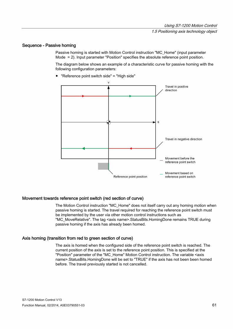
Using S7-1200 Motion Control 1.5 Positioning axis technology object
S7-1200 Motion Control V13 Function Manual, 02/2014, A5E03790551-03 61
Sequence - Passive homing Passive homing is started with Motion Control instruction "MC_Home" (input parameter Mode = 2). Input parameter "Position" specifies the absolute reference point position.
The diagram below shows an example of a characteristic curve for passive homing with the following configuration parameters:
● "Reference point switch side" = "High side"
Movement towards reference point switch (red section of curve) The Motion Control instruction "MC_Home" does not itself carry out any homing motion when passive homing is started. The travel required for reaching the reference point switch must be implemented by the user via other motion control instructions such as "MC_MoveRelative". The tag <axis name>.StatusBits.HomingDone remains TRUE during passive homing if the axis has already been homed.
Axis homing (transition from red to green section of curve) The axis is homed when the configured side of the reference point switch is reached. The current position of the axis is set to the reference point position. This is specified at the "Position" parameter of the "MC_Home" Motion Control instruction. The variable <axis name>.StatusBits.HomingDone will be set to "TRUE" if the axis has not been been homed before. The travel previously started is not cancelled.

Using S7-1200 Motion Control 1.5 Positioning axis technology object
S7-1200 Motion Control V13 62 Function Manual, 02/2014, A5E03790551-03
Movement beyond reference point switch (green section of curve) Following homing at the reference point switch, the axis continues and completes the previously started travel with the corrected axis position.
Sequence - Active homing You start active homing with motion control instruction "MC_Home" (input parameter Mode = 3). The "Position" input parameter specifies the absolute home position. Alternatively, you can start active homing on the axis command table for test purposes.
The diagram below shows an example of a characteristic curve for an active reference point approach with the following configuration parameters:
● "Approach/homing direction" = "Positive direction"
● "Side of the homing switch" = "Top side"
● Value of "home position offset" > 0
Search for homing switch (blue curve section) When active homing starts, the axis accelerates to the configured "approach velocity" and searches at this velocity for the homing switch. The tag <axis name>.StatusBits.HomingDone is set to FALSE.
Using S7-1200 Motion Control 1.5 Positioning axis technology object
S7-1200 Motion Control V13 Function Manual, 02/2014, A5E03790551-03 63
Reference point approach (red curve section) When the homing switch is detected, the axis in this example brakes and reverses, to be homed to the configured side of the homing switch at the configured homing velocity. Homing causes the tag <axis name>.StatusBits.HomingDone to change to TRUE.
Travel to home position offset (green curve segment) After homing, the axis moves at the homing velocity along the path to the home position offset. There the axis is at the homing point position that was specified in input parameter "Position" of the "MC_Home" Motion Control instruction.
See also Configuration - Homing - General (Axis technology object V2...3) (Page 200)
Using S7-1200 Motion Control 1.5 Positioning axis technology object
S7-1200 Motion Control V13 64 Function Manual, 02/2014, A5E03790551-03
Changing the homing configuration in the user program With positioning axis technology object as of V2, you can change the following configuration parameters during runtime of the user program in the CPU:
Passive homing You can change the end of the homing switch for passive homing during the user program runtime. Use the following technology object tag for this purpose:
● <Axis name>.Sensor[1].PassiveHoming.SideInput
for changing the end of the homing switch
Refer to the description of the technology object tags (Page 165) in the appendix for information on when changes to the configuration parameter take effect.
Active homing You can change the direction of approach, the end of the homing switch, the approach velocity, the homing velocity, and the home position offset for active homing during the program runtime of the user program. Use the following technology object tags for this purpose:
● <Axis name>.Homing.AutoReversal
for changing the auto reverse at the HW limit switch
● <Axis name>.Homing.ApproachDirection
for changing the approach/homing direction
● <Axis name>.Sensor[1].ActiveHoming.SideInput
for changing the end of the homing switch
● <Axis name>.Homing.ApproachVelocity
for changing the approach velocity
● <Axis name>.Homing.ReferencingVelocity
for changing the homing velocity
● <Axis name>.Sensor[1].ActiveHoming.HomePositionOffset
for changing the home position offset
Refer to the description of the technology object tags in the appendix for information on when changes to the configuration parameter take effect.
See also Compatibility list of tags (Page 27)
MC_ChangeDynamic: Change dynamic settings of axis V4 (Page 275)
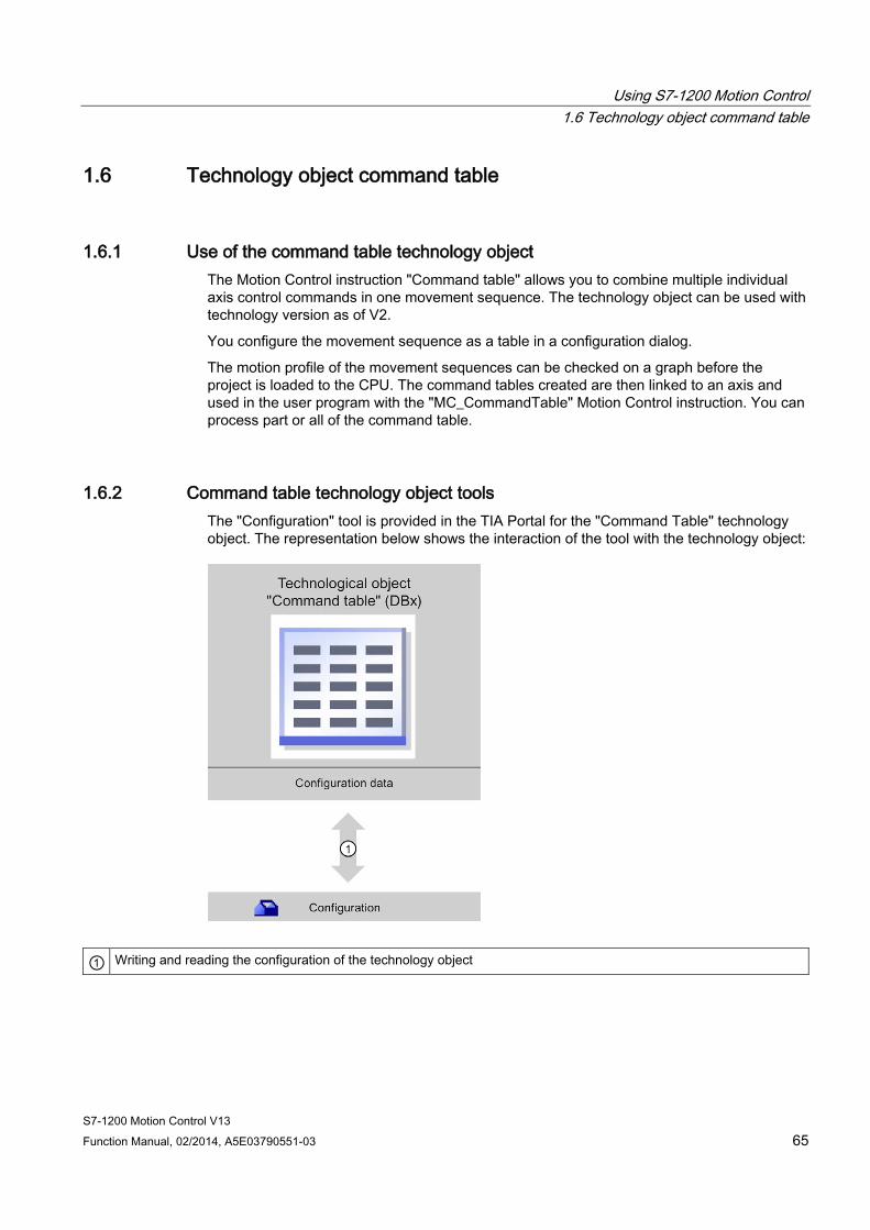
Using S7-1200 Motion Control 1.6 Technology object command table
S7-1200 Motion Control V13 Function Manual, 02/2014, A5E03790551-03 65
1.6 Technology object command table
1.6.1 Use of the command table technology object The Motion Control instruction "Command table" allows you to combine multiple individual axis control commands in one movement sequence. The technology object can be used with technology version as of V2.
You configure the movement sequence as a table in a configuration dialog.
The motion profile of the movement sequences can be checked on a graph before the project is loaded to the CPU. The command tables created are then linked to an axis and used in the user program with the "MC_CommandTable" Motion Control instruction. You can process part or all of the command table.
1.6.2 Command table technology object tools The "Configuration" tool is provided in the TIA Portal for the "Command Table" technology object. The representation below shows the interaction of the tool with the technology object:
① Writing and reading the configuration of the technology object
Using S7-1200 Motion Control 1.6 Technology object command table
S7-1200 Motion Control V13 66 Function Manual, 02/2014, A5E03790551-03
Configuration Configure the following properties of the "Command Table" technology object with the "Configuration" tool:
● You can create one or more movement sequences by configuring individual jobs.
● You can configure the graphic display to check your movement sequence using an axis already configured or a configurable default axis.
The movement sequence data are saved in the data block of the technology object.
1.6.3 Adding the technological object command table
Requirements ● A project with a CPU S7-1200 has been created.
● The CPU firmware version is V2.1 or higher
Procedure Proceed as follows to add a "Command table" technology object in the project tree:
1. Open the "CPU > Technology objects" folder in the project tree.
2. Double-click the "Add new object" command.
The "Add new object" dialog opens.
3. Select the "Motion Control" technology.
4. Open the "Motion Contro > S7-1200 Motion Control" folder.
5. Select the desired technology version in the "Version" column.
6. Select the "TO_CommandTable" object.
7. Enter the name of the command table in the "Name" input box.
8. To change the automatically assigned data block number, select the "Manual" option.
9. To display additional information about the technology object, click "Additional information".
10. Confirm your entry with "OK".
Result The new technology object is created and saved to the "Technology objects" folder in the project tree.

Using S7-1200 Motion Control 1.6 Technology object command table
S7-1200 Motion Control V13 Function Manual, 02/2014, A5E03790551-03 67
1.6.4 Configuring the command table technology object
1.6.4.1 Working with the configuration dialog You configure the properties of the technology object in the configuration window. Proceed as follows to open the configuration window of the technology object:
1. Open the group of the required technology object in the project tree.
2. Double-click the "Configuration" object.
The configuration is divided into the following categories:
● Basic parameters
The basic parameters contain all parameters which must be configured for a functional command table.
● Extended parameters
The extended parameters contain the parameters of the default axis or display the parameter values of the axis selected.
Configuration window icons Icons in the area navigation of the configuration show additional details about the status of the configuration:
The configuration contains default values and is complete.
The configuration contains only default values. With these default values, you can use the technology object without additional changes.
The configuration contains values set by the user and is complete. All input fields of the configuration contain valid values and at least one preset value has changed.
The configuration is incomplete or incorrect At least one input field or drop-down list contains an invalid value. The corresponding field or the drop-down list is displayed on a red background. Click the roll-out error message to display the cause of the error.
The configuration contains mutually incompatible parameter values The configuration contains parameter values that contradict each other either in size or logic. The corresponding field or the drop-down list is displayed on a yellow background.
See also Guidelines on use of motion control (Page 23)
Basic parameters (Page 69)
Extended parameters (Page 83)
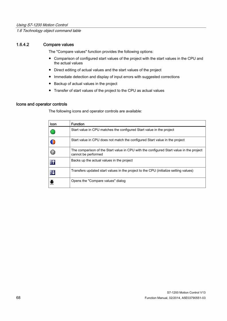
Using S7-1200 Motion Control 1.6 Technology object command table
S7-1200 Motion Control V13 68 Function Manual, 02/2014, A5E03790551-03
1.6.4.2 Compare values The "Compare values" function provides the following options:
● Comparison of configured start values of the project with the start values in the CPU and the actual values
● Direct editing of actual values and the start values of the project
● Immediate detection and display of input errors with suggested corrections
● Backup of actual values in the project
● Transfer of start values of the project to the CPU as actual values
Icons and operator controls The following icons and operator controls are available:
Icon Function
Start value in CPU matches the configured Start value in the project
Start value in CPU does not match the configured Start value in the project
The comparison of the Start value in CPU with the configured Start value in the project cannot be performed
Backs up the actual values in the project
Transfers updated start values in the project to the CPU (initialize setting values)
Opens the "Compare values" dialog

Using S7-1200 Motion Control 1.6 Technology object command table
S7-1200 Motion Control V13 Function Manual, 02/2014, A5E03790551-03 69
1.6.4.3 Basic parameters
Configuration - General Configure the name of the technology object in the "General" configuration window.
Name Define the name of the command table or the name of the "Command table" technology object in this field. The technology object will be listed under this name in the project tree.
See also Configuration - Command table (Page 69)
Shortcut menu commands - Command table (Page 73)
Working with the trend diagram (Page 75)
Shortcut menu commands - Curve chart (Page 78)
Transition from "Complete command" to "Blend motion" (Page 79)
Changing the command table configuration in the user program (Page 82)
Configuration - Command table Create the desired movement sequence in the "Command Table" configuration window and check the result against the graphic view in the trend diagram.
Note
Small deviations are possible between the time behavior and position in the trend shown and the real movement of the axis. Movements in response to software limit switches being reached are not shown.
Activate warnings Activate the display of warnings in the command table with this checkbox.
Use axis parameters of From the drop-down list, select which axis parameters are to be used for selecting the graphic view of and checking the movement sequence. Select "Default axis" if you have yet to add an axis to the "Technology object" folder or wish to use value which have not been configured in any of the available axes. You configure the properties of the default axis under "Advanced parameters".
The axis parameters of the axis selected at the "Axis" parameter are used to process the command table in the user program.
Using S7-1200 Motion Control 1.6 Technology object command table
S7-1200 Motion Control V13 70 Function Manual, 02/2014, A5E03790551-03
Column: Step Shows the step number of the command.
Column: Command type In this column, select the command types which are to be used for processing the command table. Up to 32 commands can be entered. The commands will be processed in sequence. You can choose between the following entries and command types:
● Empty
The entry serves as a placeholder for any commands to be added. The empty entry is ignored when the command table is processed.
● Halt
Stop axis (the command only takes effect after a "Velocity set point" command)
● Positioning Relative
Position axis relatively
● Positioning Absolute
Position axis absolutely
● Velocity set point
Move axis at set velocity
● Wait
Waits until the given period is over. Wait does not stop active traversing.
● Separator
Adds a Separator line above the selected line. The Separator line acts as a range limit for the graphic display of the trend view.
Use the Separator lines if you wish to process parts of the command table.

Using S7-1200 Motion Control 1.6 Technology object command table
S7-1200 Motion Control V13 Function Manual, 02/2014, A5E03790551-03 71
Column: Position Enter the position or travel path for the selected command in this column:
● Command "Positioning Relative"
The command will move the axis by the the given travel path.
● Command "Positioning Absolute"
The command will move the axis by the the given position.
● Separator
The value given specifies the start position for the graphic display.
Limit values (independent of the selected user unit):
● -1.0e12 ≤ position / distance ≤ -1.0e-12
● 1.0e-12 ≤ position / distance ≤ 1.0e12
● Position / travel path = 0.0
Column: Velocity In this column, you enter the velocity for the selected command:
● Command "Positioning Relative"
The command will move the axis at the the given velocity.
The given velocity will not be reached if the travel path selected is not large enough.
● Command "Positioning Absolute"
The command will move the axis at the the given velocity.
The given velocity will not be reached if the target position is too close to the starting position.
● Command " Velocity set point"
The command will move the axis at the the given velocity.
The given velocity will not be reached during the command if too short a runtime is selected.
Limit values (independent of the selected user unit):
● For the commands: "Positioning Relative" and "Positioning Absolute"
– 1.0e-12 ≤ velocity ≤ 1.0e12
● For the command: "Velocity set point"
– -1.0e12 ≤ velocity ≤ -1.0e-12
– 1.0e-12 ≤ velocity ≤ 1.0e12
– Velocity = 0.0

Using S7-1200 Motion Control 1.6 Technology object command table
S7-1200 Motion Control V13 72 Function Manual, 02/2014, A5E03790551-03
Column: Duration Enter the duration of the selected command in this column:
● Command " Velocity set point"
The command will move the axis for the specified duration. The duration includes both the acceleration phase and the constant travel phase. The next command will be processed once the duration is over.
● Command "Wait"
Waits until the given duration is over.
Limit values (independent of the selected user unit):
● 0.001s ≤ duration ≤ 64800s
Column: Next step Select the mode of transition to the next step from the drop-down list:
● Complete command
The command will be completed. The next command will be processed immediately.
● Blend motion
The motion of the current command will be blended with the motion of the following command. The transition mode "Blend motion" is available with command types "Positioning Relative" and "Positioning Absolute".
Motion will be blended with motions of the following command types:
– Positioning Relative
– Positioning Absolute
– Velocity set point
No blending occurs with other command types.
For the exact behavior of the axis when a command is appended or overlapped, see: Transition from "Complete command" to "Blend motion" (Page 79)
Column: Step code Enter a numerical value / bit pattern in this column which is to be output at the "StepCode" output parameter of the "MC_CommandTable" Motion Control instruction while the command is being processed.
Limit values:
● 0 ≤ code number ≤ 65535
Using S7-1200 Motion Control 1.6 Technology object command table
S7-1200 Motion Control V13 Function Manual, 02/2014, A5E03790551-03 73
See also Configuration - General (Page 69)
Shortcut menu commands - Command table (Page 73)
Working with the trend diagram (Page 75)
Shortcut menu commands - Curve chart (Page 78)
Transition from "Complete command" to "Blend motion" (Page 79)
Changing the command table configuration in the user program (Page 82)
Shortcut menu commands - Command table The following shortcut menu commands are available in the command table:
Insert empty line Adds an empty line above the selected line.
This shortcut menu command can only be executed if there are enough empty lines at the end of the command table.
Add empty line Adds an empty line below the selected line.
This shortcut menu command can only be executed if there are enough empty lines at the end of the command table.
Insert separator line Adds a separator line above the selected line.
You cannot have two consecutive separator lines.
Add separator line Adds a separator line below the selected line.
You cannot have two consecutive separator lines, nor can you add a separator line at the end of the command table.
Cut Removes the selected lines or content of the selected cell and saves them/it in the clipboard.
Selected lines will be deleted and the subsequent lines of the command table shifted up.
Copy Copies the selected lines or content of the selected cell and saves them/it in the clipboard.
Using S7-1200 Motion Control 1.6 Technology object command table
S7-1200 Motion Control V13 74 Function Manual, 02/2014, A5E03790551-03
Paste ● Selected lines:
Pastes the lines from the clipboard into the table above the selected line.
● Selected cell:
Pastes the content of the clipboard into the selected line.
This shortcut menu command can only be executed if there are enough empty lines at the end of the command table.
Replace Replaces the selected lines with the lines in the clipboard.
Delete Deletes the selected lines. The lines below in the command table shift up.
See also Configuration - General (Page 69)
Configuration - Command table (Page 69)
Working with the trend diagram (Page 75)
Shortcut menu commands - Curve chart (Page 78)
Transition from "Complete command" to "Blend motion" (Page 79)
Changing the command table configuration in the user program (Page 82)
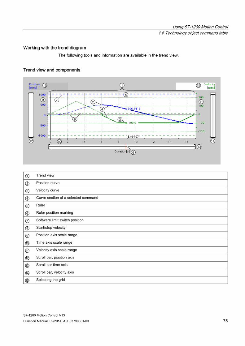
Using S7-1200 Motion Control 1.6 Technology object command table
S7-1200 Motion Control V13 Function Manual, 02/2014, A5E03790551-03 75
Working with the trend diagram The following tools and information are available in the trend view.
Trend view and components
① Trend view
② Position curve
③ Velocity curve
④ Curve section of a selected command
⑤ Ruler
⑥ Ruler position marking
⑦ Software limit switch position
⑧ Start/stop velocity
⑨ Position axis scale range
⑩ Time axis scale range
⑪ Velocity axis scale range
⑫ Scroll bar, position axis
⑬ Scroll bar time axis
⑭ Scroll bar, velocity axis
⑮ Selecting the grid
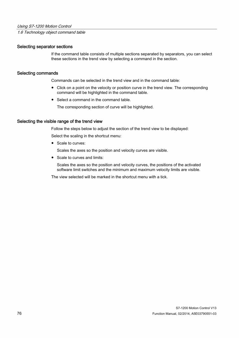
Using S7-1200 Motion Control 1.6 Technology object command table
S7-1200 Motion Control V13 76 Function Manual, 02/2014, A5E03790551-03
Selecting separator sections If the command table consists of multiple sections separated by separators, you can select these sections in the trend view by selecting a command in the section.
Selecting commands Commands can be selected in the trend view and in the command table:
● Click on a point on the velocity or position curve in the trend view. The corresponding command will be highlighted in the command table.
● Select a command in the command table.
The corresponding section of curve will be highlighted.
Selecting the visible range of the trend view Follow the steps below to adjust the section of the trend view to be displayed:
Select the scaling in the shortcut menu:
● Scale to curves:
Scales the axes so the position and velocity curves are visible.
● Scale to curves and limits:
Scales the axes so the position and velocity curves, the positions of the activated software limit switches and the minimum and maximum velocity limits are visible.
The view selected will be marked in the shortcut menu with a tick.
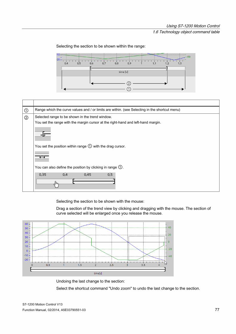
Using S7-1200 Motion Control 1.6 Technology object command table
S7-1200 Motion Control V13 Function Manual, 02/2014, A5E03790551-03 77
Selecting the section to be shown within the range:
① Range which the curve values and / or limits are within. (see Selecting in the shortcut menu)
② Selected range to be shown in the trend window. You set the range with the margin cursor at the right-hand and left-hand margin.
You set the position within range ① with the drag cursor.
You can also define the position by clicking in range ①.
Selecting the section to be shown with the mouse:
Drag a section of the trend view by clicking and dragging with the mouse. The section of curve selected will be enlarged once you release the mouse.
Undoing the last change to the section:
Select the shortcut command "Undo zoom" to undo the last change to the section.
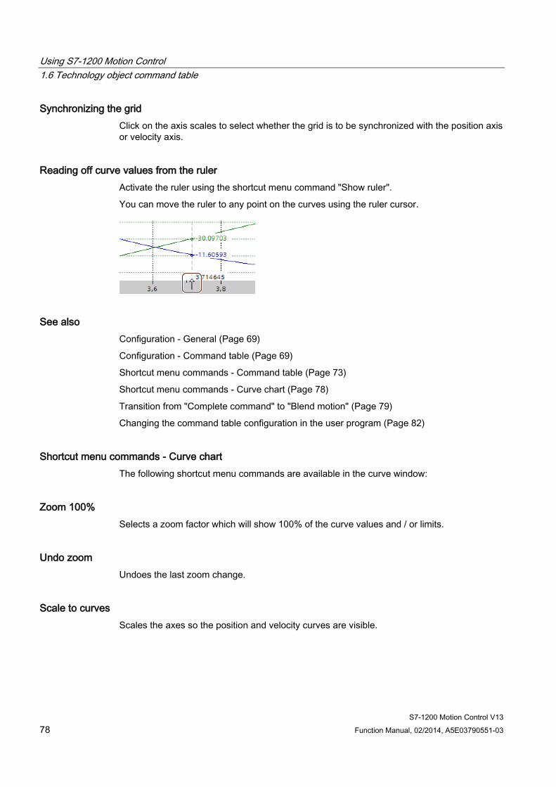
Using S7-1200 Motion Control 1.6 Technology object command table
S7-1200 Motion Control V13 78 Function Manual, 02/2014, A5E03790551-03
Synchronizing the grid Click on the axis scales to select whether the grid is to be synchronized with the position axis or velocity axis.
Reading off curve values from the ruler Activate the ruler using the shortcut menu command "Show ruler".
You can move the ruler to any point on the curves using the ruler cursor.
See also Configuration - General (Page 69)
Configuration - Command table (Page 69)
Shortcut menu commands - Command table (Page 73)
Shortcut menu commands - Curve chart (Page 78)
Transition from "Complete command" to "Blend motion" (Page 79)
Changing the command table configuration in the user program (Page 82)
Shortcut menu commands - Curve chart The following shortcut menu commands are available in the curve window:
Zoom 100% Selects a zoom factor which will show 100% of the curve values and / or limits.
Undo zoom Undoes the last zoom change.
Scale to curves Scales the axes so the position and velocity curves are visible.
Using S7-1200 Motion Control 1.6 Technology object command table
S7-1200 Motion Control V13 Function Manual, 02/2014, A5E03790551-03 79
Scale to curves and limits Scales the axes so the position and velocity curves, the positions of the activated software limit switches and the minimum and maximum velocity limits are visible.
Show velocity limits Shows the lines of the velocity limits.
Show software limit switches Shows the lines of the software limit switches.
Show ruler Fades the ruler in / out
Use the ruler when you want to see the individual values of the curves.
See also Configuration - General (Page 69)
Configuration - Command table (Page 69)
Shortcut menu commands - Command table (Page 73)
Working with the trend diagram (Page 75)
Transition from "Complete command" to "Blend motion" (Page 80)
Changing the command table configuration in the user program (Page 82)

Using S7-1200 Motion Control 1.6 Technology object command table
S7-1200 Motion Control V13 80 Function Manual, 02/2014, A5E03790551-03
Transition from "Complete command" to "Blend motion" The charts below show the transition between movements in various different transition modes in the "Next step" column:
Motion transition with preceding positioning jobs The following diagrams show a command sequence with two motion tasks. The first command is for positioning (green). The second command is for velocity (red) or positioning (blue):
Complete job Blend motion
Transition from lower to higher velocity
A job with high velocity is appended to a previous positioning job. The positioning job terminates at its target position at velocity "0". The second job starts from standstill.
Transition from lower to higher velocity
A job with high velocity is overlapped with a previous positioning job. The first positioning job terminates without standstill at its target position. The second job starts with the new velocity.
Transition from higher to lower velocity
A job with low velocity is appended to a previous positioning job. The positioning job terminates at its target position at velocity "0". The second job starts from standstill.
Transition from higher to lower velocity
A job with low velocity is overlapped with a previous positioning job. The first positioning job terminates without standstill at its target position. The first job starts with the new velocity.
1. Job "Positioning Relative" or "Positioning Absolute"
2. Job "Velocity set point"
2. Job "Positioning Relative" or "Positioning Absolute"
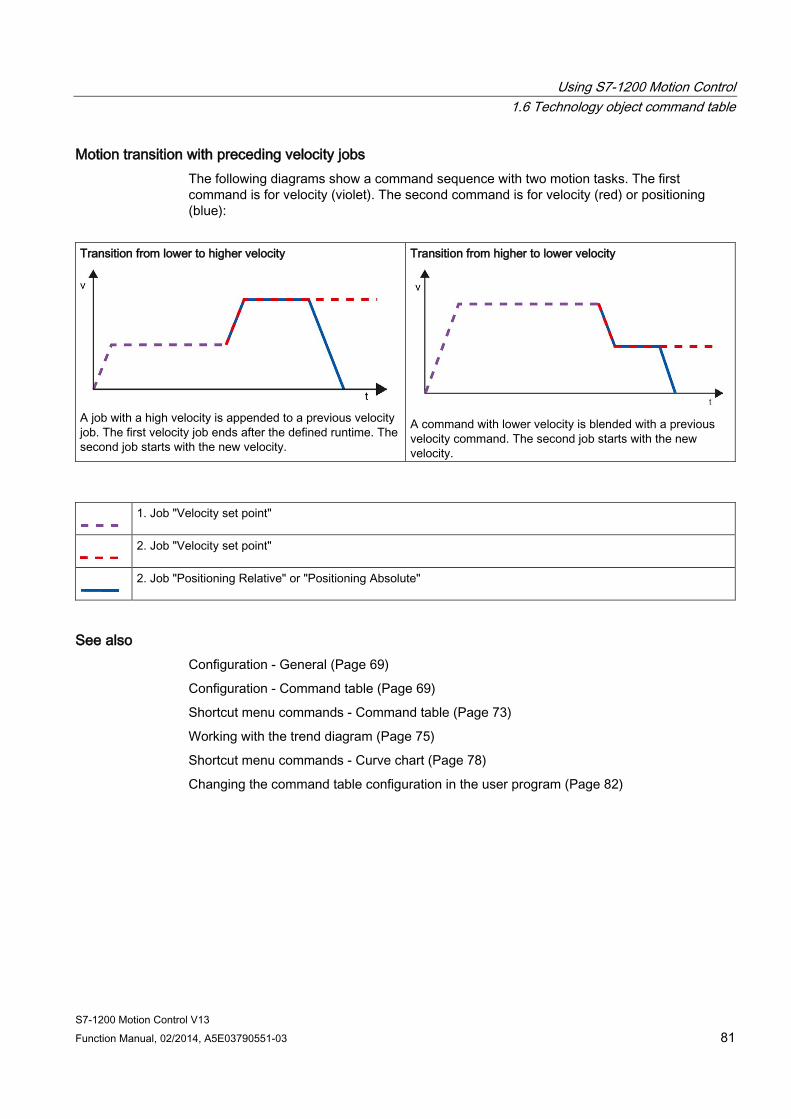
Using S7-1200 Motion Control 1.6 Technology object command table
S7-1200 Motion Control V13 Function Manual, 02/2014, A5E03790551-03 81
Motion transition with preceding velocity jobs The following diagrams show a command sequence with two motion tasks. The first command is for velocity (violet). The second command is for velocity (red) or positioning (blue):
Transition from lower to higher velocity
A job with a high velocity is appended to a previous velocity job. The first velocity job ends after the defined runtime. The second job starts with the new velocity.
Transition from higher to lower velocity
A command with lower velocity is blended with a previous velocity command. The second job starts with the new velocity.
1. Job "Velocity set point"
2. Job "Velocity set point"
2. Job "Positioning Relative" or "Positioning Absolute"
See also Configuration - General (Page 69)
Configuration - Command table (Page 69)
Shortcut menu commands - Command table (Page 73)
Working with the trend diagram (Page 75)
Shortcut menu commands - Curve chart (Page 78)
Changing the command table configuration in the user program (Page 82)

Using S7-1200 Motion Control 1.6 Technology object command table
S7-1200 Motion Control V13 82 Function Manual, 02/2014, A5E03790551-03
Changing the command table configuration in the user program You can change the following configuration parameters during runtime of the user program in the CPU:
Commands and corresponding values You can also change the parameters of the command table during the runtime of the user program. Use the following technology object tags for this purpose:
● <Table name>.Command[1..32].Type
for changing the command type
● <Table name>.Command[1..32].Position
for changing the position/travel distance
● <Table name>.Command[1..32].Velocity
for changing the velocity
● <Table name>.Command[1..32].Duration
for changing the duration
● <Table name>.Command[1..32].NextStep
for changing the parameter "Next step"
● <Table name>.Command[1..32].StepCode
for changing the step code
Refer to the description of the technology object tags (Page 188) in the appendix for information on when changes to the configuration parameters take effect.
See also Compatibility list of tags (Page 27)
Configuration - General (Page 69)
Configuration - Command table (Page 69)
Shortcut menu commands - Command table (Page 73)
Working with the trend diagram (Page 75)
Shortcut menu commands - Curve chart (Page 78)
Transition from "Complete command" to "Blend motion" (Page 79)

Using S7-1200 Motion Control 1.6 Technology object command table
S7-1200 Motion Control V13 Function Manual, 02/2014, A5E03790551-03 83
1.6.4.4 Extended parameters
Chart parameters
Configuration - General Configure the basic properties of the chart view of the "Command table" technology object in the "General" configuration window.
Note
If the default axis has been selected under "Use axis parameters of", the unit of measurement can be edited. If a configured axis has been selected, the unit of measurement for this axis will be displayed.
Use axis parameters of From the drop-down list, select which axis parameters are to be used for selecting the graphic view of and checking the movement sequence. Select "Default axis" if you have yet to add an axis to the "Technology object" folder or wish to use values which have not been configured in any of the available axes.
The axis parameters of the axis selected at the "Axis" parameter will be used to process the command table in the user program.
Unit of measurement Enter the unit of measurement for the default axis in this field. If a preconfigured axis has been selected under "Use axis parameters of", the unit of measurement configured in these parameter will be displayed.
Configuration - Dynamics Configure the acceleration and deceleration and the jerk limit for the default axis in the "Dynamics" configuration window.
Note
If the default axis has been selected under "Use axis parameters of", the following fields can be edited. If a configured axis has been selected, the values of this axis will be displayed.
Using S7-1200 Motion Control 1.6 Technology object command table
S7-1200 Motion Control V13 84 Function Manual, 02/2014, A5E03790551-03
Acceleration / deceleration Set the desired acceleration of the default axis in the "Acceleration" field. The desired deceleration can be set in the "Deceleration" field.
Motion jobs configured in the command table will be calculated with the selected acceleration / deceleration.
Limit values:
● 1.0e-12 ≤ acceleration ≤ 1.0e12
● 1.0e-12 ≤ deceleration ≤ 1.0e12
Activate jerk limit Activate the jerk limit with this checkbox.
Step Set the desired step for ramping up and ramping down in the "Step" field.
Motion jobs configured in the command table will be calculated with the selected step.
Limit values:
● 1.0e-12 ≤ jerk ≤ 1.0e12
Configuration - Limit values Configure the maximum velocity, the start/stop velocity and the software limit switches of the default axis in the "Limits" configuration window.
Note
If the default axis has been selected under "Use axis parameters of", the following fields can be edited. If a configured axis has been selected, the values of this axis will be displayed.
Using S7-1200 Motion Control 1.6 Technology object command table
S7-1200 Motion Control V13 Function Manual, 02/2014, A5E03790551-03 85
Maximum velocity / Start/stop velocity Define the maximum permissible velocity and the start/stop velocity of the default axis in these fields. The start/stop velocity is the minimum permissible velocity of the default axis.
Limit values:
● 1.0e-12 ≤ start/stop velocity ≤ 1.0e12
Start/stop velocity = 0.0
● 1.0e-12 ≤ maximum velocity ≤ 1.0e12
Maximum velocity = 0.0
The value of the maximum velocity must be greater or equal to the value of the start/stop velocity.
Enable software limit switches Activate the function of the low and high software limit switch with this checkbox. Movements in response to software limit switches being reached are not shown in the trend view.
Low / high software limit switch Enter the position value of the low and high software limit switches in these fields.
Limits:
● -1.0e12 ≤ low software limit switch ≤ -1.0e-12
1.0e-12 ≤ low software limit switch ≤ 1.0e12
Low software limit switch = 0.0
● -1.0e12 ≤ high software limit switch ≤ -1.0e-12
1.0e-12 ≤ high software limit switch ≤ 1.0e12
High software limit switch = 0.0
The value of the high software limit switch must be greater than or equal to the value of the low software limit switch.
Using S7-1200 Motion Control 1.7 Download to CPU
S7-1200 Motion Control V13 86 Function Manual, 02/2014, A5E03790551-03
1.7 Download to CPU When loading to the CPU S7-1200 always ensure that the project files are consistent after the online and offline loading. It is not possible to load single blocks. When selecting single blocks, all new and modified blocks are always loaded.
The following object groups can be loaded to the CPU:
Context menu command "Download to device"
Description
All Download all new and modified blocks and a new or modified hardware configuration Hardware configuration Download a new or modified hardware configuration Software Download all new and modified blocks Software (all blocks) Download all blocks
The data of the Motion Control technology objects are saved in the data blocks. The conditions for downloading of "blocks" thus apply when loading a new or modified technology object.
CAUTION
Possible malfunctions of the axis when loading without hardware configuration
The hardware configuration is modified when the following modifications are made to the axis configuration: • Modification of the pulse generator (PTO) • Modification of the HW limit switch address • Modification of the homing switch address
If the modified configuration of the axis is loaded with the context menu commands "Software" or "Software (all blocks)" without downloading the hardware configuration, this can lead to malfunctions of the axis.
Ensure that the current hardware configuration is downloaded to the CPU under the conditions listed below.
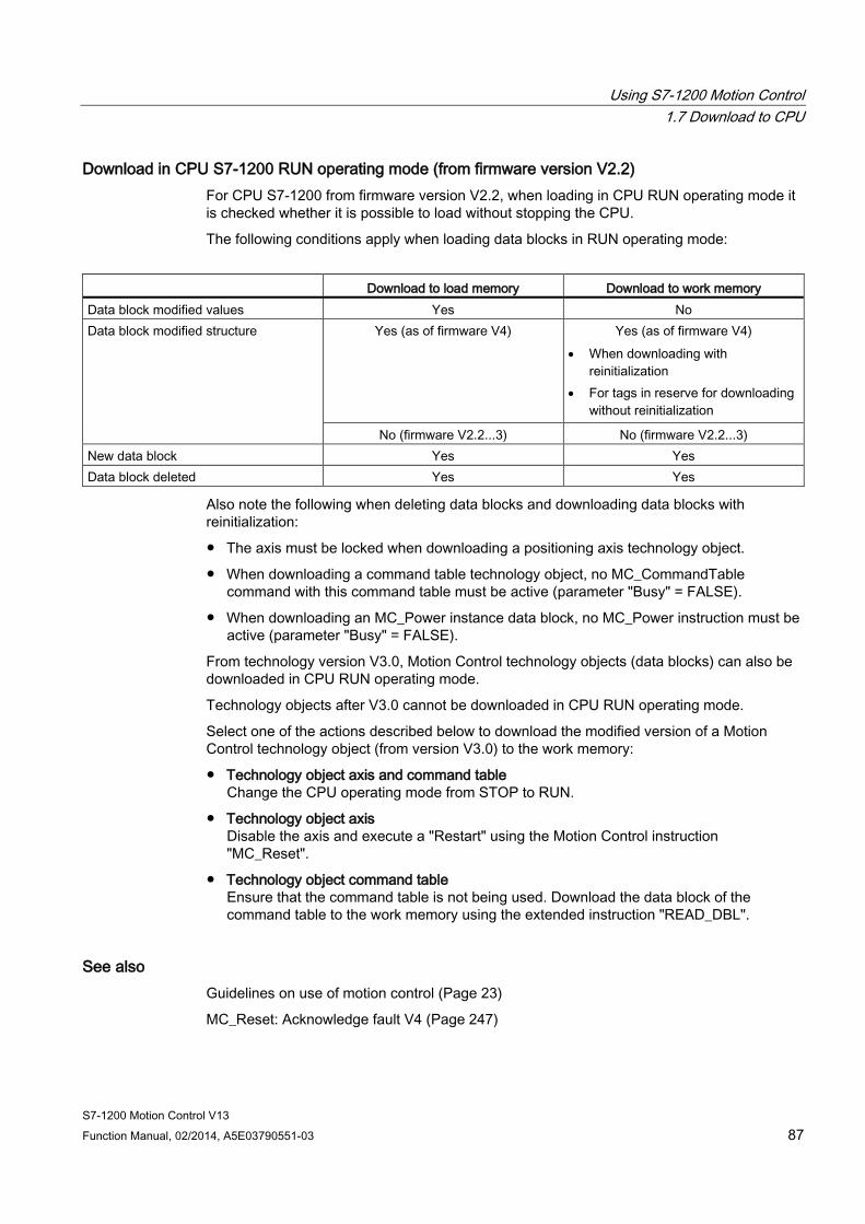
Using S7-1200 Motion Control 1.7 Download to CPU
S7-1200 Motion Control V13 Function Manual, 02/2014, A5E03790551-03 87
Download in CPU S7-1200 RUN operating mode (from firmware version V2.2) For CPU S7-1200 from firmware version V2.2, when loading in CPU RUN operating mode it is checked whether it is possible to load without stopping the CPU.
The following conditions apply when loading data blocks in RUN operating mode:
Download to load memory Download to work memory Data block modified values Yes No Data block modified structure Yes (as of firmware V4) Yes (as of firmware V4)
• When downloading with reinitialization
• For tags in reserve for downloading without reinitialization
No (firmware V2.2...3) No (firmware V2.2...3) New data block Yes Yes Data block deleted Yes Yes
Also note the following when deleting data blocks and downloading data blocks with reinitialization:
● The axis must be locked when downloading a positioning axis technology object.
● When downloading a command table technology object, no MC_CommandTable command with this command table must be active (parameter "Busy" = FALSE).
● When downloading an MC_Power instance data block, no MC_Power instruction must be active (parameter "Busy" = FALSE).
From technology version V3.0, Motion Control technology objects (data blocks) can also be downloaded in CPU RUN operating mode.
Technology objects after V3.0 cannot be downloaded in CPU RUN operating mode.
Select one of the actions described below to download the modified version of a Motion Control technology object (from version V3.0) to the work memory:
● Technology object axis and command table Change the CPU operating mode from STOP to RUN.
● Technology object axis Disable the axis and execute a "Restart" using the Motion Control instruction "MC_Reset".
● Technology object command table Ensure that the command table is not being used. Download the data block of the command table to the work memory using the extended instruction "READ_DBL".
See also Guidelines on use of motion control (Page 23)
MC_Reset: Acknowledge fault V4 (Page 247)
Using S7-1200 Motion Control 1.8 Commissioning the axis - Axis control panel
S7-1200 Motion Control V13 88 Function Manual, 02/2014, A5E03790551-03
1.8 Commissioning the axis - Axis control panel Use the axis command table to move the axis in manual mode, to optimize the axis settings, and to test your system.
The axis control table can only be used if an online connection to the CPU is established.
Note Response times of the axis control panel
The response time during axis control table operation depends on the communication load of the CPU. Close all other online windows of the TIA Portal to minimize the response time.
"Manual control" button Click "Manual control" to move the axis in manual control mode. Start by disabling the axis in the user program using Motion Control instruction "MC_Power". In "Manual control" mode, the axis control table takes over control priority for the axis functions. The user program has no influence on the axis functions until manual control is ended.
CAUTION
Additional axes in automatic mode
The Manual control is active for one axis only. If additional axes are in automatic mode, dangerous situations may arise as a result.
In this happens, disable all other axes.
"Automatic mode" button Click "Automatic mode" to end the "Manual control" mode. The axis control table passes back the control priority and the axis can be controlled by the user program again. The axis must be re-enabled in the user program and homed, if required.
Complete all active traversing motions before switching to automatic control; otherwise, the axis will be braked with the emergency stop deceleration.
"Enable" button Click "Enable" to enable the axis in "Manual control" mode. When the axis is enabled, the axis control panel functions can be used.
If the axis cannot be enabled because certain conditions are not met, note the error message in the "Error message" box. Information on eliminating errors is available in the appendix under "List of ErrorIDs and ErrorInfos". After the error has been corrected, enable the axis again.
Using S7-1200 Motion Control 1.8 Commissioning the axis - Axis control panel
S7-1200 Motion Control V13 Function Manual, 02/2014, A5E03790551-03 89
"Disable" button Click "Disable" if you want to temporarily disable the axis in "Manual control" mode.
"Command" area Operation in the "Command" area is only possible if the axis is enabled. You can select one of the following command inputs:
● Jogging
This command is equivalent to Motion Control command "MC_MoveJog" in the user program.
● Positioning
This command is equivalent to the Motion Control commands "MC_MoveAbsolute" and "MC_MoveRelative" in the user program. The axis must be homed for absolute positioning.
● Homing
This command is equivalent to Motion Control command "MC_Home" in the user program.
– The "Set reference point" button corresponds to Mode = 0 (direct homing absolute)
– The "Active homing" button corresponds to Mode = 3 (active homing)
For active homing, the homing switch must be configured in the axis configuration.
The values for approach velocity, homing velocity, and reference position offset are taken from the axis configuration unchanged.
Depending on the selection, the relevant boxes for entry of setpoints and the buttons for starting the command are displayed.
Jerk limitation can be activated and deactivated using the "Activate jerk limit" button. By default, the jerk is applied with 10% of the configured value. This value can be changed as required.
"Axis status" area If "Manual control" mode is activated, the current axis status and drive status are shown in the "Axis status" area. The current position and velocity of the axis are displayed at "Process values".
Click "Acknowledge" to acknowledge all cleared errors.
The "Info message" box displays advanced information about the status of the axis.
"Current values" area This area displays the current position and velocity of the axis.
Using S7-1200 Motion Control 1.8 Commissioning the axis - Axis control panel
S7-1200 Motion Control V13 90 Function Manual, 02/2014, A5E03790551-03
Error message The "Error message" box shows the current error. In "Manual control" mode, the error entry can be deleted by pressing the "Acknowledge" button once the error is eliminated.
Note Initial values for velocity, acceleration / deceleration and jerk
For safety reasons, the "Velocity", "Acceleration/deceleration" and "Jerk" parameters are initialized with values equivalent to only 10% of the configured values when the axis command table is activated. The "Jerk" parameter is only used for technology object "Axis" V2.0 and higher.
The values in the configuration view displayed when you select "Extended parameters > Dynamics > General" are used for initialization.
The "Velocity" parameter on the control panel is derived from the "Maximum velocity" and the "Acceleration/deceleration" parameters from "Acceleration" in the configuration.
The "Velocity", "Acceleration/deceleration" and "Jerk" parameters can be changed in the axis command table; this does not affect the values in the configuration.
See also Guidelines on use of motion control (Page 23)
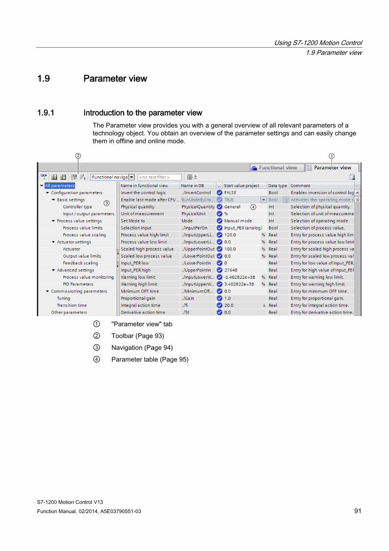
Using S7-1200 Motion Control 1.9 Parameter view
S7-1200 Motion Control V13 Function Manual, 02/2014, A5E03790551-03 91
1.9 Parameter view
1.9.1 Introduction to the parameter view The Parameter view provides you with a general overview of all relevant parameters of a technology object. You obtain an overview of the parameter settings and can easily change them in offline and online mode.
① "Parameter view" tab
② Toolbar (Page 93)
③ Navigation (Page 94)
④ Parameter table (Page 95)
Using S7-1200 Motion Control 1.9 Parameter view
S7-1200 Motion Control V13 92 Function Manual, 02/2014, A5E03790551-03
Function scope The following functions are available for analyzing the parameters of the technology objects and for enabling targeted monitoring and modification.
Display functions: ● Display of parameter values in offline and online mode ● Display of status information of the parameters ● Display of value deviations and option for direct correction ● Display of configuration errors ● Display of value changes as a result of parameter dependencies ● Display of all memory values of a parameter: Start value PLC, Start value project, Monitor
value ● Display of the parameter comparison of the memory values of a parameter
Operator control functions: ● Navigation for quickly changing between the parameters and parameter structures. ● Text filter for faster searches for particular parameters. ● Sorting function for customizing the order of parameters and parameter groups to
requirements. ● Memory function for backing up structural settings of the Parameter view. ● Monitoring and modifying of parameter values online. ● Function for saving a snapshot of parameter values of the CPU in order to capture
momentary situations and to respond to them. ● Function for applying a snapshot of parameter values as start values. ● Download of modified start values to the CPU. ● Comparison functions for comparing parameter values with one another.
Validity The Parameter view is available for the following technology objects:
● PID_Compact
● PID_3Step
● CONT_C (S7-1500 only)
● CONT_S (S7-1500 only)
● TCONT_CP (S7-1500 only)
● TCONT_S (S7-1500 only)
● TO_Axis_PTO (S7-1200 Motion Control)
● TO_Positioning_Axis (S7-1200 Motion Control)
● TO_CommandTable_PTO (S7-1200 Motion Control)
● TO_CommandTable (S7-1200 Motion Control)
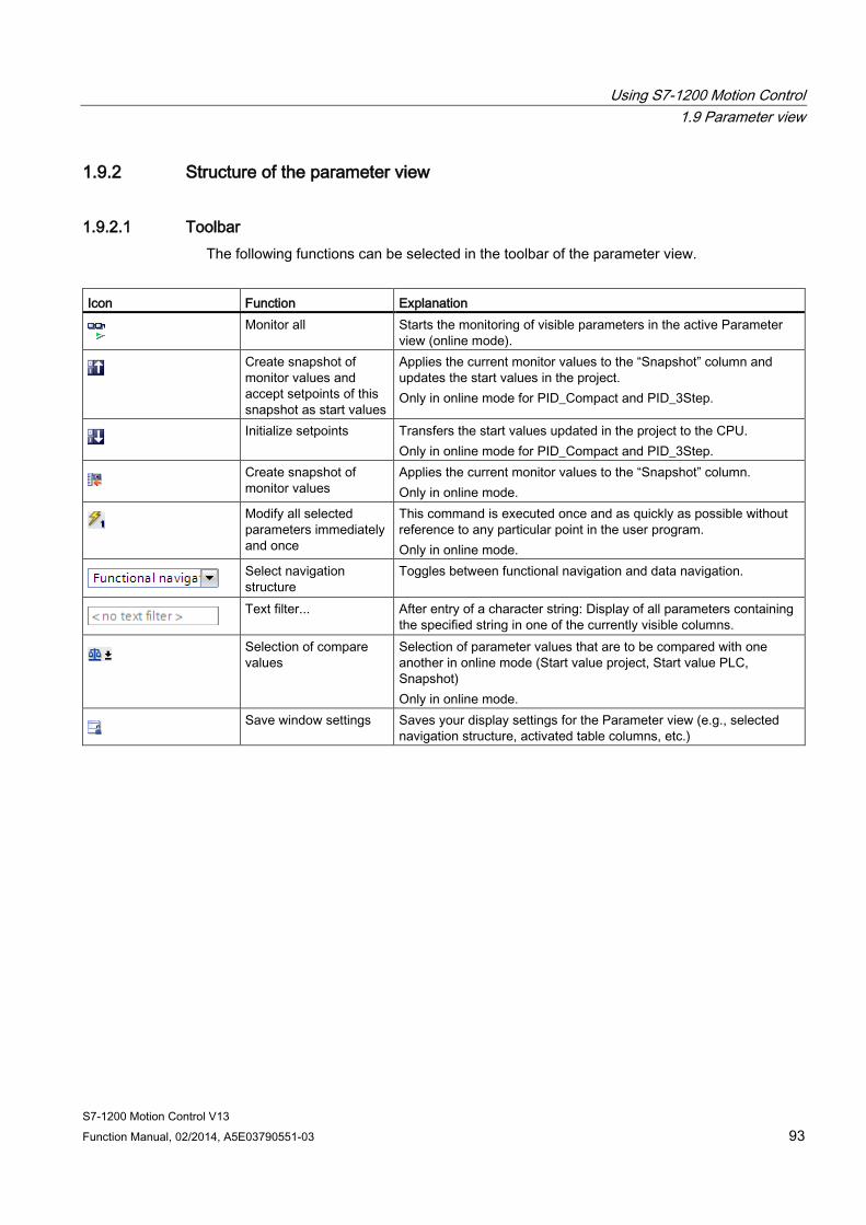
Using S7-1200 Motion Control 1.9 Parameter view
S7-1200 Motion Control V13 Function Manual, 02/2014, A5E03790551-03 93
1.9.2 Structure of the parameter view
1.9.2.1 Toolbar The following functions can be selected in the toolbar of the parameter view.
Icon Function Explanation
Monitor all Starts the monitoring of visible parameters in the active Parameter
view (online mode).
Create snapshot of monitor values and accept setpoints of this snapshot as start values
Applies the current monitor values to the “Snapshot” column and updates the start values in the project. Only in online mode for PID_Compact and PID_3Step.
Initialize setpoints Transfers the start values updated in the project to the CPU.
Only in online mode for PID_Compact and PID_3Step.
Create snapshot of monitor values
Applies the current monitor values to the “Snapshot” column. Only in online mode.
Modify all selected parameters immediately and once
This command is executed once and as quickly as possible without reference to any particular point in the user program. Only in online mode.
Select navigation structure
Toggles between functional navigation and data navigation.
Text filter... After entry of a character string: Display of all parameters containing
the specified string in one of the currently visible columns.
Selection of compare values
Selection of parameter values that are to be compared with one another in online mode (Start value project, Start value PLC, Snapshot) Only in online mode.
Save window settings Saves your display settings for the Parameter view (e.g., selected
navigation structure, activated table columns, etc.)
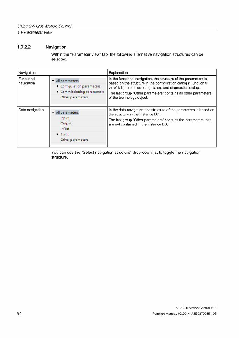
Using S7-1200 Motion Control 1.9 Parameter view
S7-1200 Motion Control V13 94 Function Manual, 02/2014, A5E03790551-03
1.9.2.2 Navigation Within the "Parameter view" tab, the following alternative navigation structures can be selected.
Navigation Explanation Functional navigation
In the functional navigation, the structure of the parameters is based on the structure in the configuration dialog ("Functional view" tab), commissioning dialog, and diagnostics dialog. The last group "Other parameters" contains all other parameters of the technology object.
Data navigation
In the data navigation, the structure of the parameters is based on the structure in the instance DB. The last group "Other parameters" contains the parameters that are not contained in the instance DB.
You can use the "Select navigation structure" drop-down list to toggle the navigation structure.
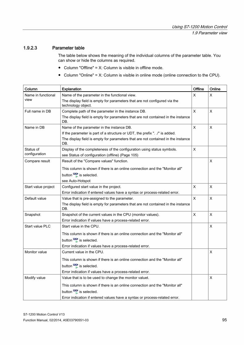
Using S7-1200 Motion Control 1.9 Parameter view
S7-1200 Motion Control V13 Function Manual, 02/2014, A5E03790551-03 95
1.9.2.3 Parameter table The table below shows the meaning of the individual columns of the parameter table. You can show or hide the columns as required.
● Column "Offline" = X: Column is visible in offline mode.
● Column "Online" = X: Column is visible in online mode (online connection to the CPU).
Column Explanation Offline Online Name in functional view
Name of the parameter in the functional view. The display field is empty for parameters that are not configured via the technology object.
X X
Full name in DB Complete path of the parameter in the instance DB. The display field is empty for parameters that are not contained in the instance DB.
X X
Name in DB Name of the parameter in the instance DB. If the parameter is part of a structure or UDT, the prefix ". ./" is added. The display field is empty for parameters that are not contained in the instance DB.
X X
Status of configuration
Display of the completeness of the configuration using status symbols. see Status of configuration (offline) (Page 105)
X
Compare result Result of the "Compare values" function.
This column is shown if there is an online connection and the "Monitor all" button is selected. see Auto-Hotspot
X
Start value project Configured start value in the project. Error indication if entered values have a syntax or process-related error.
X X
Default value Value that is pre-assigned to the parameter. The display field is empty for parameters that are not contained in the instance DB.
X X
Snapshot Snapshot of the current values in the CPU (monitor values). Error indication if values have a process-related error.
X X
Start value PLC Start value in the CPU.
This column is shown if there is an online connection and the "Monitor all" button is selected. Error indication if values have a process-related error.
X
Monitor value Current value in the CPU.
This column is shown if there is an online connection and the "Monitor all" button is selected. Error indication if values have a process-related error.
X
Modify value Value that is to be used to change the monitor valuet.
This column is shown if there is an online connection and the "Monitor all" button is selected. Error indication if entered values have a syntax or process-related error.
X
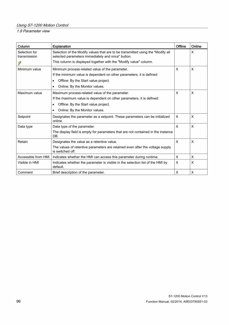
Using S7-1200 Motion Control 1.9 Parameter view
S7-1200 Motion Control V13 96 Function Manual, 02/2014, A5E03790551-03
Column Explanation Offline Online Selection for transmission
Selection of the Modify values that are to be transmitted using the "Modify all selected parameters immediately and once" button. This column is displayed together with the "Modify value" column.
X
Minimum value Minimum process-related value of the parameter. If the minimum value is dependent on other parameters, it is defined: • Offline: By the Start value project. • Online: By the Monitor values.
X X
Maximum value Maximum process-related value of the parameter. If the maximum value is dependent on other parameters, it is defined: • Offline: By the Start value project. • Online: By the Monitor values.
X X
Setpoint Designates the parameter as a setpoint. These parameters can be initialized online.
X X
Data type Data type of the parameter. The display field is empty for parameters that are not contained in the instance DB.
X X
Retain Designates the value as a retentive value. The values of retentive parameters are retained even after the voltage supply is switched off.
X X
Accessible from HMI Indicates whether the HMI can access this parameter during runtime. X X Visible in HMI Indicates whether the parameter is visible in the selection list of the HMI by
default. X X
Comment Brief description of the parameter. X X

Using S7-1200 Motion Control 1.9 Parameter view
S7-1200 Motion Control V13 Function Manual, 02/2014, A5E03790551-03 97
1.9.3 Opening the parameter view
Requirement The technology object has been added in the project tree, i.e., the associated instance DB of the instruction has been created.
Procedure 1. Open the "Technology objects" folder in the project tree.
2. Open the technology object in the project tree.
3. Double-click the "Configuration" object.
4. Select the "Parameter view" tab in the top right corner.
Result The Parameter view opens. Each displayed parameter is represented by one row in the parameter table.
The displayable parameter properties (table columns) vary depending on whether you are working with the Parameter view in offline or online mode.
In addition, you can selectively display and hide individual table columns.
See also Default setting of the parameter view (Page 98)
Using S7-1200 Motion Control 1.9 Parameter view
S7-1200 Motion Control V13 98 Function Manual, 02/2014, A5E03790551-03
1.9.4 Default setting of the parameter view
Default settings To enable you to work efficiently with the Parameter view, you can customize the parameter display and save your settings.
The following customizations are possible and can be saved:
● Show and hide columns
● Change column width
● Change order of the columns
● Toggle navigation
● Select parameter group in the navigation
● Selection of compare values
Show and hide columns To show or hide columns in the parameter table, follow these steps:
1. Position the cursor in the header of the parameter table.
2. Select the "Show/Hide" command in the shortcut menu. The selection of available columns is displayed.
3. To show a column, select the check box for the column.
4. To hide a column, clear the check box for the column.
or
1. Position the cursor in the header of the parameter table.
2. Select the "Show all columns" command in the shortcut menu if all columns of the offline or online mode are to be displayed.
Some columns can only be displayed in online mode: see Parameter table (Page 95).
Using S7-1200 Motion Control 1.9 Parameter view
S7-1200 Motion Control V13 Function Manual, 02/2014, A5E03790551-03 99
Change column width To customize the width of a column so that all texts in the rows can be read, follow these steps:
1. Position the cursor in the header of the parameter table to the right of the column to be customized until the shape of the cursor changes to a cross.
2. Then double-click this location.
or
1. Open the shortcut menu on the header of the parameter table.
2. Click
– "Optimize column width" or
– "Optimize width of all columns".
If the column width setting is too narrow, the complete content of individual fields are shown if you hover the cursor briefly over the relevant field.
Change order of the columns The columns of the parameter table can be arranged in any way.
To change the order of the columns, follow these steps:
1. Click on the column header and use a drag-and-drop operation to move it to the desired location.
When you release the mouse button, the column is anchored to the new position.
Toggle navigation To toggle the display form of the parameters, follow these steps:
1. Select the desired navigation in the “Select navigation structure” drop-down list.
– Data navigation
– Functional navigation
See also Navigation (Page 94).
Select parameter group in the navigation Within the selected navigation, you choose between the “All parameters” display or the display of a subordinate parameter group of your choice.
1. Click the desired parameter group in the navigation.
The parameter table only displays the parameters of the parameter group.
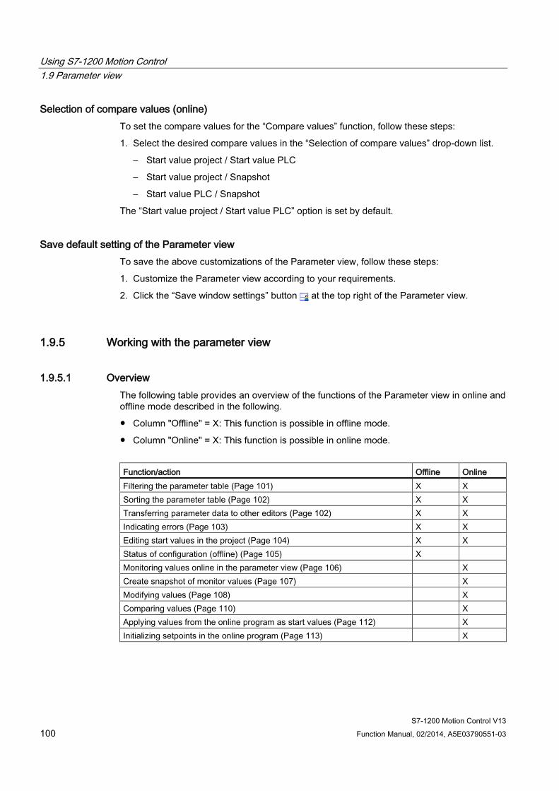
Using S7-1200 Motion Control 1.9 Parameter view
S7-1200 Motion Control V13 100 Function Manual, 02/2014, A5E03790551-03
Selection of compare values (online) To set the compare values for the “Compare values” function, follow these steps:
1. Select the desired compare values in the “Selection of compare values” drop-down list.
– Start value project / Start value PLC
– Start value project / Snapshot
– Start value PLC / Snapshot
The “Start value project / Start value PLC” option is set by default.
Save default setting of the Parameter view To save the above customizations of the Parameter view, follow these steps:
1. Customize the Parameter view according to your requirements.
2. Click the “Save window settings” button at the top right of the Parameter view.
1.9.5 Working with the parameter view
1.9.5.1 Overview The following table provides an overview of the functions of the Parameter view in online and offline mode described in the following.
● Column "Offline" = X: This function is possible in offline mode.
● Column "Online" = X: This function is possible in online mode.
Function/action Offline Online Filtering the parameter table (Page 101) X X Sorting the parameter table (Page 102) X X Transferring parameter data to other editors (Page 102) X X Indicating errors (Page 103) X X Editing start values in the project (Page 104) X X Status of configuration (offline) (Page 105) X Monitoring values online in the parameter view (Page 106) X Create snapshot of monitor values (Page 107) X Modifying values (Page 108) X Comparing values (Page 110) X Applying values from the online program as start values (Page 112) X Initializing setpoints in the online program (Page 113) X
Using S7-1200 Motion Control 1.9 Parameter view
S7-1200 Motion Control V13 Function Manual, 02/2014, A5E03790551-03 101
1.9.5.2 Filtering the parameter table You can filter the parameters in the parameter table in the following ways:
● With the text filter
● With the subgroups of the navigation
Both filter methods can be used simultaneously.
With the text filter Texts that are visible in the parameter table can be filtered. This means only texts in displayed parameter rows and columns can be filtered.
1. Enter the desired character string for filtering in the “Text filter...” input box.
The parameter table displays only the parameters containing the character string.
The text filtering is reset.
● When another parameter group is selected in the navigation.
● When navigation is changed from data navigation to functional navigation, or vice versa.
With the subgroups of the navigation 1. Click the desired parameter group in the navigation, e.g., "Static".
The parameter table only shows the static parameters. You can select further subgroups for some groups of the navigation.
2. Click “All parameters” in the navigation if all parameters are to be shown again.
Using S7-1200 Motion Control 1.9 Parameter view
S7-1200 Motion Control V13 102 Function Manual, 02/2014, A5E03790551-03
1.9.5.3 Sorting the parameter table The values of the parameters are arranged in rows. The parameter table can be sorted by any displayed column.
● In columns containing numerical values, sorting is based on the magnitude of the numerical value.
● In text columns, sorting is alphabetical.
Sorting by column 1. Position the cursor in the header cell of the desired column.
The background of this cell turns blue.
2. Click the column header.
Result The entire parameter table is sorted by the selected column. A triangle with tip facing up appears in the column header.
Clicking the column header again changes the sorting as follows:
● Symbol “▲”: Parameter table is sorted in ascending order.
● Symbol “▼”: Parameter table is sorted in descending order.
● No symbol: The sorting is removed again. The parameter table assumes the default display.
The “../“ prefix in the “Name in DB” column is ignored when sorting.
1.9.5.4 Transferring parameter data to other editors After selecting an entire parameter row of the parameter table, you can use the following:
● Drag-and-drop
● <Ctrl+C>/<Ctrl+V>
● Copy/Paste via shortcut menu
Transfer parameters to the following editors of the TIA Portal:
● Program editor
● Watch table
● Signal table for trace function
The parameter is inserted with its full name: See information in “Full name in DB” column.
Using S7-1200 Motion Control 1.9 Parameter view
S7-1200 Motion Control V13 Function Manual, 02/2014, A5E03790551-03 103
1.9.5.5 Indicating errors
Error indication Parameter assignment errors that result in compilation errors (e.g., limit violation) are indicated in the Parameter view.
Every time a value is input in the Parameter view, a check is made for process-related and syntax errors and the result is indicated.
Bad values are indicated by:
● Red error symbol in the "Status of configuration" (offline mode) or "Compare result" (online mode, depending on the selected comparison type) columns
and/or
● Table field with red background
If you click the bad field, a roll-out error message appears with information of the permissible value range or the required syntax (format)
Compilation error From the error message of the compiler, you can directly open the Parameter view (functional navigation) containing the parameter causing the error in situations where the parameter is not displayed in the configuration dialog.
Using S7-1200 Motion Control 1.9 Parameter view
S7-1200 Motion Control V13 104 Function Manual, 02/2014, A5E03790551-03
1.9.5.6 Editing start values in the project With the Parameter view, you can edit the start values in the project in offline mode and online mode.
● You make value changes in the “Start value project” column of the parameter table.
● In the “Status of configuration” column of the parameter table, the progress of the configuration is indicated by the familiar status symbols from the configuration dialog of the technology object.
Boundary conditions ● If other parameters depend on the parameter whose start value was changed, the start
value of the dependent parameters are also adapted.
● If a parameter of a technology object is not editable, it is also not editable in the parameter view. The ability to edit a parameter can also depend on the values of other parameters.
Defining new start values To define start values for parameters in the Parameter view, follow these steps:
1. Open the Parameter view of the technology object.
2. Enter the desired start values in the "Start value project" column. The value must match the data type of the parameter and must not exceed the value range of the parameter. The limits of the value range can be seen in the “Maximum value” and “Minimum value” columns.
The "Status of configuration" column indicates the progress of the configuration with colored symbols.
See also Status of configuration (offline) (Page 105)
Following adaptation of the start values and downloading of the technology object to the CPU, the parameters take the defined value at startup if they are not declared as retentive (“Retain” column).
Error indication When a start value is input, a check is made for process-related and syntax errors and the result is indicated.
Bad start values are indicated by:
● Red error symbol in the "Status of configuration" (offline mode) or "Compare result" (online mode, depending on the selected comparison type) columns
and/or
● Red background in the “Start value project” field If you click on the bad field, a roll-out error message appears with information of the permissible value range or the necessary syntax (format)
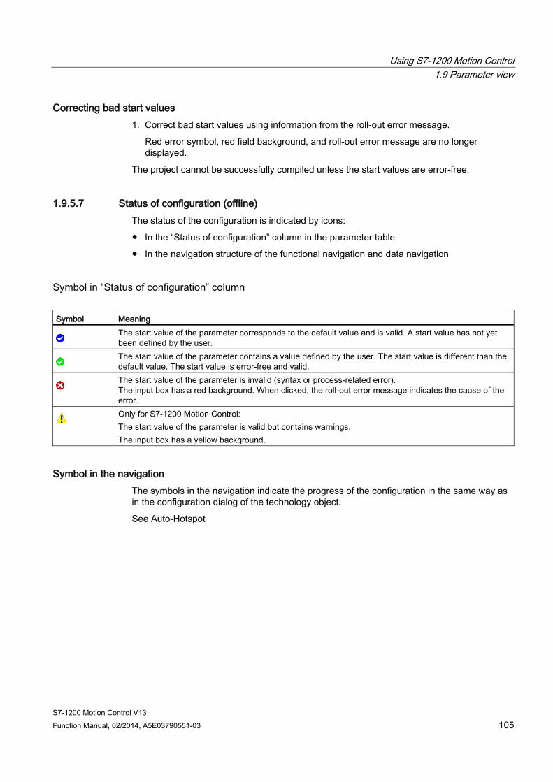
Using S7-1200 Motion Control 1.9 Parameter view
S7-1200 Motion Control V13 Function Manual, 02/2014, A5E03790551-03 105
Correcting bad start values 1. Correct bad start values using information from the roll-out error message.
Red error symbol, red field background, and roll-out error message are no longer displayed.
The project cannot be successfully compiled unless the start values are error-free.
1.9.5.7 Status of configuration (offline) The status of the configuration is indicated by icons:
● In the “Status of configuration” column in the parameter table
● In the navigation structure of the functional navigation and data navigation
Symbol in “Status of configuration” column Symbol Meaning
The start value of the parameter corresponds to the default value and is valid. A start value has not yet been defined by the user.
The start value of the parameter contains a value defined by the user. The start value is different than the default value. The start value is error-free and valid.
The start value of the parameter is invalid (syntax or process-related error). The input box has a red background. When clicked, the roll-out error message indicates the cause of the error.
Only for S7-1200 Motion Control: The start value of the parameter is valid but contains warnings. The input box has a yellow background.
Symbol in the navigation The symbols in the navigation indicate the progress of the configuration in the same way as in the configuration dialog of the technology object.
See Auto-Hotspot
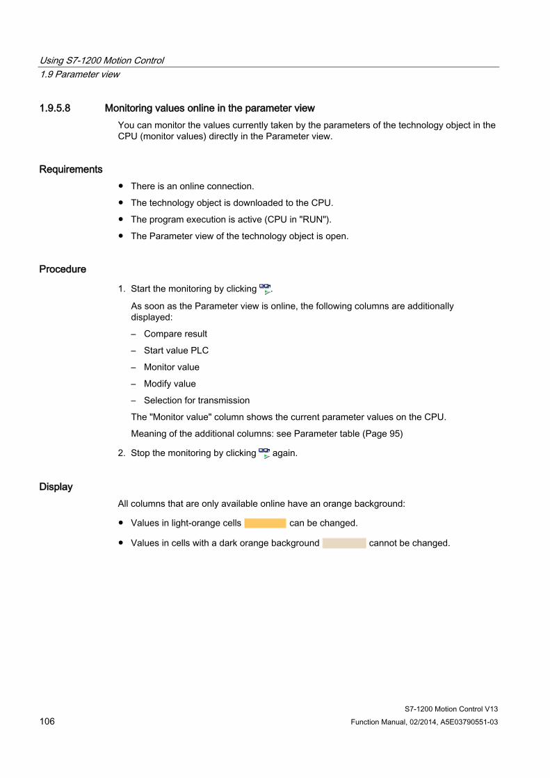
Using S7-1200 Motion Control 1.9 Parameter view
S7-1200 Motion Control V13 106 Function Manual, 02/2014, A5E03790551-03
1.9.5.8 Monitoring values online in the parameter view You can monitor the values currently taken by the parameters of the technology object in the CPU (monitor values) directly in the Parameter view.
Requirements ● There is an online connection.
● The technology object is downloaded to the CPU.
● The program execution is active (CPU in "RUN").
● The Parameter view of the technology object is open.
Procedure
1. Start the monitoring by clicking .
As soon as the Parameter view is online, the following columns are additionally displayed:
– Compare result
– Start value PLC
– Monitor value
– Modify value
– Selection for transmission
The "Monitor value" column shows the current parameter values on the CPU.
Meaning of the additional columns: see Parameter table (Page 95)
2. Stop the monitoring by clicking again.
Display All columns that are only available online have an orange background:
● Values in light-orange cells can be changed.
● Values in cells with a dark orange background cannot be changed.
Using S7-1200 Motion Control 1.9 Parameter view
S7-1200 Motion Control V13 Function Manual, 02/2014, A5E03790551-03 107
1.9.5.9 Create snapshot of monitor values You can back up the current values of the technology object on the CPU (monitor values) and display them in the Parameter view.
Requirements ● There is an online connection.
● The technology object is downloaded to the CPU.
● The program execution is active (CPU in "RUN").
● The Parameter view of the technology object is open.
● The “Monitor all” button is selected.
Procedure To show the current parameter values, follow these steps:
1. In the Parameter view, click the “Create snapshot of monitor values" icon .
Result The current monitor values are transferred once to the "Snapshot" column of the parameter table.
You can analyze the values "frozen" in this way while the monitor values continue to be updated in the "Monitor values" column.
Using S7-1200 Motion Control 1.9 Parameter view
S7-1200 Motion Control V13 108 Function Manual, 02/2014, A5E03790551-03
1.9.5.10 Modifying values With the Parameter view, you can modify values of the technology object in the CPU.
You can assign values to the parameter once (Modify value) and modify them immediately. The modify request is executed as quickly as possible without reference to any particular point in the user program.
DANGER
Danger when modifying:
Changing the parameter values while the plant is operating may result in severe damage to property and personal injury in the event of malfunctions or program errors.
Make sure that dangerous states cannot occur before you use the "Modify" function.
Requirements ● There is an online connection.
● The technology object is downloaded to the CPU.
● The program execution is active (CPU in "RUN").
● The Parameter view of the technology object is open.
● The “Monitor all” button is selected.
● The parameter can be modified (associated field in the "Modify value" column has a light-orange background).
Procedure To modify parameters immediately, follow these steps:
1. Enter the desired modify values in the “Modify values” column of the parameter table.
2. Check whether the check box for modifying is selected in the "Select for transmission" column.
The modify values and associated check boxes of dependent parameters are automatically adapted at the same time.
3. Click the “Modify all selected parameters immediately and once” icon .
The selected parameters are modified once and immediately with the specified values and can be monitored in the "Modify values" column. The check boxes for modifying in the "Selection for transmission" column are automatically cleared after the modify request is complete.
Using S7-1200 Motion Control 1.9 Parameter view
S7-1200 Motion Control V13 Function Manual, 02/2014, A5E03790551-03 109
Error indication When a start value is input, a check is made immediately for process-related and syntax errors and the result is indicated.
Bad start values are indicated by:
● Red background in the “Modify value” field
and
● If you click the bad field, a roll-out error message appears with information of the permissible value range or the necessary syntax (format)
Bad modify values ● Modify values with process-related errors can be transmitted.
● Modify values with syntax errors cannot be transmitted.
Using S7-1200 Motion Control 1.9 Parameter view
S7-1200 Motion Control V13 110 Function Manual, 02/2014, A5E03790551-03
1.9.5.11 Comparing values You can use comparison functions to compare the following memory values of a parameter:
● Start value project
● Start value PLC
● Snapshot
Requirements ● There is an online connection.
● The technology object is downloaded to the CPU.
● The program execution is active (CPU in "RUN").
● The Parameter view of the technology object is open.
● The “Monitor all” button is selected.
Procedure To compare the start values on the various target systems, follow these steps:
1. Click the "Selection of compare values" icon .
A selection list containing the comparison options opens:
– Start value project - Start value PLC (default setting)
– Start value project - Snapshot
– Start value PLC - Snapshot
2. Select the desired comparison option.
The selected comparison option is executed as follows:
– A scales symbol appears in the header cells of the two columns selected for comparison.
– Symbols are used in the "Compare result" column to indicate the result of the comparison of the selected columns.
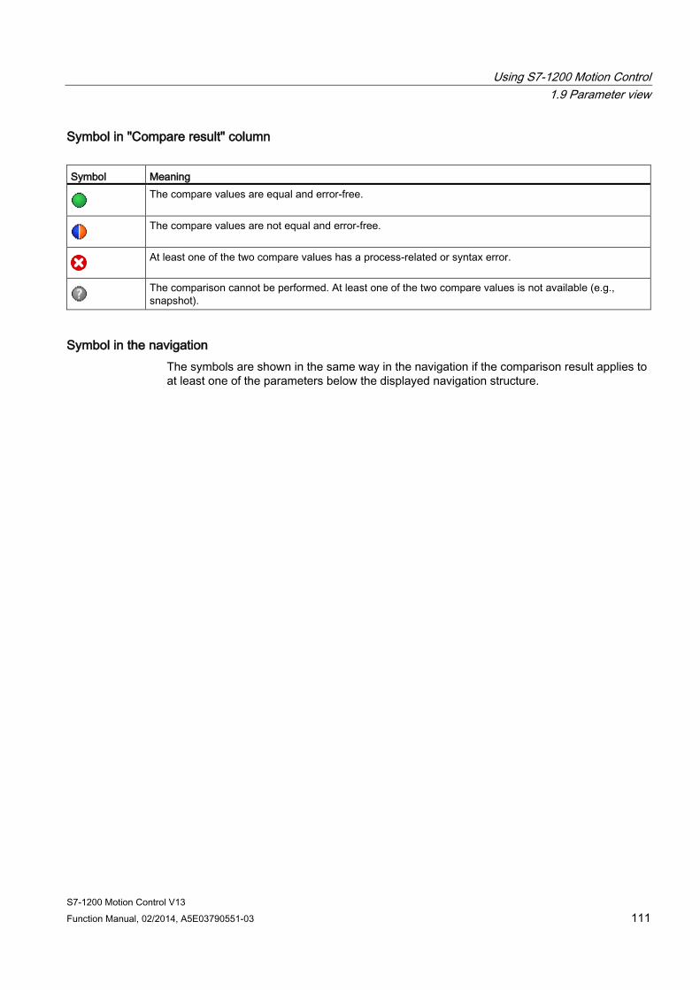
Using S7-1200 Motion Control 1.9 Parameter view
S7-1200 Motion Control V13 Function Manual, 02/2014, A5E03790551-03 111
Symbol in "Compare result" column Symbol Meaning
The compare values are equal and error-free.
The compare values are not equal and error-free.
At least one of the two compare values has a process-related or syntax error.
The comparison cannot be performed. At least one of the two compare values is not available (e.g., snapshot).
Symbol in the navigation The symbols are shown in the same way in the navigation if the comparison result applies to at least one of the parameters below the displayed navigation structure.

Using S7-1200 Motion Control 1.9 Parameter view
S7-1200 Motion Control V13 112 Function Manual, 02/2014, A5E03790551-03
1.9.5.12 Applying values from the online program as start values In order to apply optimized values from the CPU to the project as start values, you create a snapshot of the monitor values. Values of the snapshot marked as a "Setpoint" are then applied to the project as start values.
Requirements ● The technology object is of type "PID_Compact" or "PID_3Step".
● There is an online connection.
● The technology object is downloaded to the CPU.
● The program execution is active (CPU in "RUN").
● The Parameter view of the technology object is open.
● The “Monitor all” button is selected.
Procedure To apply optimized values from the CPU, follow these steps:
1. Click the "Create snapshot of monitor values and accept setpoints of this snapshot as start values" icon .
Result The current monitor values are applied to the "Snapshot" column and their setpoints are copied to the "Start value project" column as new start values.
Note Applying values of individual parameters
You can also apply the values of individual parameters that are not marked as a setpoint from the "Snapshot" column to the "Start values project" column. To do so, copy the values and insert them into the "Start value project" column using the "Copy" and "Paste" commands in the shortcut menu.

Using S7-1200 Motion Control 1.9 Parameter view
S7-1200 Motion Control V13 Function Manual, 02/2014, A5E03790551-03 113
1.9.5.13 Initializing setpoints in the online program You can initialize all parameters that are marked as a "Setpoint" in the Parameter view with new values in the CPU in one step. In so doing, the start values are downloaded from the project to the CPU. The CPU remains in "RUN" mode.
To avoid data loss on the CPU during a cold restart or warm restart, you must also download the technology object to the CPU.
DANGER
Danger when changing parameter values
Changing the parameter values while the plant is operating may result in severe damage to property and personal injury in the event of malfunctions or program errors.
Make sure that dangerous states cannot occur before you reinitialize the setpoints.
Requirements ● The technology object is of type "PID_Compact" or "PID_3Step".
● There is an online connection.
● The technology object is downloaded to the CPU.
● The program execution is active (CPU in "RUN").
● The Parameter view of the technology object is open.
● The “Monitor all” button is selected.
● The parameters marked as a "Setpoint" have a "Start value project" that is free of process-related and syntax errors
Procedure To initialize all setpoints, follow these steps:
1. Enter the desired values in the "Start value project" column.
Ensure that the start values are free of process-related and syntax errors.
2. Click the "Initialize setpoints" icon .
Result The setpoints in the CPU are initialized with the start values from the project.
Using S7-1200 Motion Control 1.10 Programming
S7-1200 Motion Control V13 114 Function Manual, 02/2014, A5E03790551-03
1.10 Programming
1.10.1 Overview of the Motion Control statements You control the axis with the user program using Motion Control instructions. The instructions start Motion Control commands that execute the desired functions.
The status of the Motion Control commands and any errors that occur during their execution can be obtained from the output parameters of the Motion Control instructions. The following Motion Control instructions are available:
● MC_Power: Enable, disable axis V4 (Page 242)
● MC_Reset: Acknowledge fault V4 (Page 247)
● MC_Home: Home axes, set reference point V4 (Page 249)
● MC_Halt: Halt axes V4 (Page 253)
● MC_MoveAbsolute: Absolute positioning of axes V4 (Page 256)
● MC_MoveRelative: Relative positioning of axes V4 (Page 260)
● MC_MoveVelocity: Move axes at preset rotational speed V4 (Page 264)
● MC_MoveJog: Move axes in jog mode V4 (Page 268)
● MC_CommandTable: Run axis commands as motion sequence V4 (Page 272)
● MC_ChangeDynamic: Change dynamic settings of axis V4 (Page 275)
● MC_ReadParam: Continuously read motion data of a positioning axis V4 (Page 278)
● MC_WriteParam: Write tag of positioning axis V4 (Page 280)
See also Creating a user program (Page 115)
Programming notes (Page 118)
Behavior of the Motion Control commands after POWER OFF and restart (Page 120)
Monitoring active commands (Page 121)
Error displays of the Motion Control statements (Page 132)
Using S7-1200 Motion Control 1.10 Programming
S7-1200 Motion Control V13 Function Manual, 02/2014, A5E03790551-03 115
1.10.2 Creating a user program In the section below you learn how to create a user program with the basic configuration for controlling your axis. All available axis functions are controlled using the Motion Control instructions to be inserted.
Requirement ● The technology object has been created and configured without errors.
Before creating and testing the user program, it is advisable to test the function of the axis and the corresponding parts of the system with the axis command table.
Procedure Proceed as follows to create the user program in accordance with the principles described below:
1. In the project tree, double-click your code block (the code block must be called in the cyclic program).
The code block is opened in the programming editor and all available instructions are displayed.
2. Open the "Technology" category and the "Motion Control" and "S7-1200 Motion Control" folders.
3. Use a drag-and-drop operation to move the "MC_Power" instruction to the desired network of the code block.
The dialog box for defining the instance DB opens.
4. In the next dialog box, select from the following alternatives:
Single instance
Click "Single instance" and select whether you want to define the name and number of the instance DB automatically or manually.
Multi-instance
Click "Multi-instance" and select whether you want to define the name of the multi-instance automatically or manually.
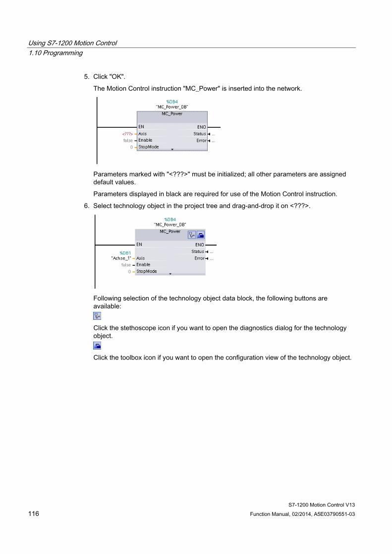
Using S7-1200 Motion Control 1.10 Programming
S7-1200 Motion Control V13 116 Function Manual, 02/2014, A5E03790551-03
5. Click "OK".
The Motion Control instruction "MC_Power" is inserted into the network.
Parameters marked with "<???>" must be initialized; all other parameters are assigned default values.
Parameters displayed in black are required for use of the Motion Control instruction.
6. Select technology object in the project tree and drag-and-drop it on <???>.
Following selection of the technology object data block, the following buttons are available:
Click the stethoscope icon if you want to open the diagnostics dialog for the technology object.
Click the toolbox icon if you want to open the configuration view of the technology object.
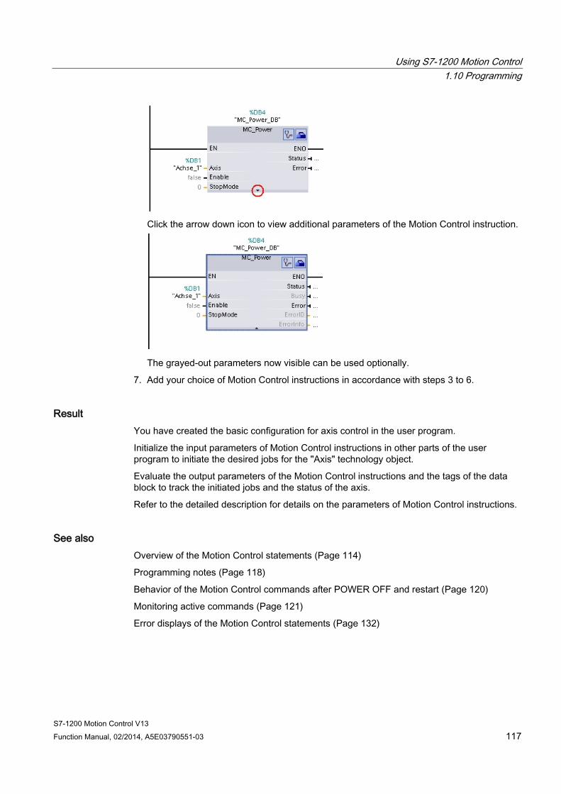
Using S7-1200 Motion Control 1.10 Programming
S7-1200 Motion Control V13 Function Manual, 02/2014, A5E03790551-03 117
Click the arrow down icon to view additional parameters of the Motion Control instruction.
The grayed-out parameters now visible can be used optionally.
7. Add your choice of Motion Control instructions in accordance with steps 3 to 6.
Result You have created the basic configuration for axis control in the user program.
Initialize the input parameters of Motion Control instructions in other parts of the user program to initiate the desired jobs for the "Axis" technology object.
Evaluate the output parameters of the Motion Control instructions and the tags of the data block to track the initiated jobs and the status of the axis.
Refer to the detailed description for details on the parameters of Motion Control instructions.
See also Overview of the Motion Control statements (Page 114)
Programming notes (Page 118)
Behavior of the Motion Control commands after POWER OFF and restart (Page 120)
Monitoring active commands (Page 121)
Error displays of the Motion Control statements (Page 132)
Using S7-1200 Motion Control 1.10 Programming
S7-1200 Motion Control V13 118 Function Manual, 02/2014, A5E03790551-03
1.10.3 Programming notes When creating your user program, note the following information:
● Cyclic call of utilized motion control instructions
The current status of command execution is available via the output parameters of the motion control instruction. The status is updated with every call of the motion control instruction. Therefore, make sure that the utilized motion control instructions are called cyclically.
● Transfer of parameter values of a motion control instruction
The parameter values pending for the input parameters are transferred with a positive edge at input parameter "Execute" when the block is called.
The motion control command is started with these parameter values. Parameter values that are subsequently changed for the motion control instruction are not transferred until the next start of the motion control command.
Exceptions to this are input parameters "StopMode" of motion control instruction "MC_Power" and "Velocity" of motion control instruction "MC_MoveJog". A change in the input parameter is also applied when "Enable" = TRUE, or "JogForward" and "JogBackward". .
● Programming under consideration of the status information
In a stepwise execution of motion control jobs, make sure to wait for the active command to finish before starting a new command. Use the status messages of the motion control instruction and the "StatusBits" tag of the technology object to check for completion of the active command.
In the examples below, observe the indicated sequence. Failure to observe the sequence will display an axis or command error.
– Axis enable with motion control instruction "MC_Power"
You must enable the axis before it can take on motion jobs. Use an AND operation of tag <Axis name>.StatusBits.Enable = TRUE with output parameter Status = TRUE of motion control instruction "MC_Power" to verify that the axis is enabled.
– Acknowledge error with motion control instruction "MC_Reset"
Prior to starting a motion control command, errors requiring acknowledgement must be acknowledged with "MC_Reset". Eliminate the cause of the error and acknowledge the error with motion control instruction "MC_Reset". Verify that the error has been successfully acknowledged before initiating a new command. For this purpose, use an AND operation of tag <Axis name>.StatusBits.Error = FALSE with output parameter Done = TRUE of motion control instruction "MC_Reset".
– Home axis with motion control instruction "MC_Home"
Before you can start an MC_MoveAbsolute command, the axis must be homed. Use an AND operation of tag <Axis name>.StatusBits.HomingDone = TRUE with output parameter Done = TRUE of motion control instruction "MC_Home" to verify that the axis has been homed.
Using S7-1200 Motion Control 1.10 Programming
S7-1200 Motion Control V13 Function Manual, 02/2014, A5E03790551-03 119
● Override of motion control command processing
Motion control jobs for moving an axis can also be executed as overriding jobs.
If a new motion control command is started for an axis while another motion control command is active, the active command is overridden by the new command before the existing command is completely executed. The overridden command signals this using CommandAborted = TRUE in the motion control instruction. It is possible to override an active MC_MoveRelative command with a MC_MoveAbsolute command.
● Avoiding multiple use of the same instance
All relevant information of a motion control command is stored in its instance.
Do not start a new command using this instance, if you want to track the status of the current command. Use different instances if you want to track the commands separately. If the same instance is used for multiple motion control commands, the status and error information of the individual commands will overwrite each other.
● Call of motion control instructions in different priority classes (run levels)
Motion Control instructions with the same instance may not be called in different priority classes without interlocking. To learn how to call locked motion control instructions, refer to "Tracking commands from higher priority classes (run levels) (Page 143)".
See also Overview of the Motion Control statements (Page 114)
Creating a user program (Page 115)
Behavior of the Motion Control commands after POWER OFF and restart (Page 120)
Monitoring active commands (Page 121)
Error displays of the Motion Control statements (Page 132)
Tracking jobs from higher priority classes (execution levels) (Page 143)
Using S7-1200 Motion Control 1.10 Programming
S7-1200 Motion Control V13 120 Function Manual, 02/2014, A5E03790551-03
1.10.4 Behavior of the Motion Control commands after POWER OFF and restart A POWER OFF or CPU-STOP aborts all active motion control jobs. All CPU outputs, including pulse and direction outputs, are reset.
After a subsequent POWER ON or CPU restart (CPU RUN), the technology objects and the motion control jobs will be reinitialized.
All actual data of the technology objects as well as all status and error information of the previously active motion control jobs are reset to their initial values.
Before the axis can be reused, it must be enabled again using the Motion Control instruction "MC_Power". If homing is required, the axis must be homed again with Motion Control instruction "MC_Home".
See also Overview of the Motion Control statements (Page 114)
Creating a user program (Page 115)
Programming notes (Page 118)
Monitoring active commands (Page 121)
Error displays of the Motion Control statements (Page 132)

Using S7-1200 Motion Control 1.10 Programming
S7-1200 Motion Control V13 Function Manual, 02/2014, A5E03790551-03 121
1.10.5 Monitoring active commands
1.10.5.1 Monitoring active commands There are three typical groups for tracking active Motion Control commands:
● Motion control instructions with output parameter "Done"
● Motion control instruction "MC_MoveVelocity"
● Motion control instruction "MC_MoveJog"
1.10.5.2 Motion control instructions with "Done" output parameter Motion control instructions with the output parameter "Done" are started via input parameter "Execute" and have a defined conclusion (for example, with Motion Control instruction "MC_Home": Homing was successful). The command is complete and the axis is at a standstill.
The commands of the following Motion Control instructions have a defined conclusion:
● MC_Reset
● MC_Home
● MC_Halt
● MC_MoveAbsolute
● MC_MoveRelative
● MC_CommandTable (technology object as of V2)
● MC_ChangeDynamic (technology object as of V2)
● MC_WriteParam (as of technology object V4)
● MC_ReadParam (as of technology object V4)
The output parameter "Done" indicates the value TRUE, if the command has been successfully completed.
The output parameters "Busy", "CommandAborted", and "Error" signal that the command is still being processed, has been aborted or an error is pending. The Motion Control instruction "MC_Reset" cannot be aborted and thus has no "CommandAborted" output parameter. The Motion Control instruction "MC_ChangeDynamic" is completed immediately and therefore has no "Busy" or "CommandAborted" output parameters.
During execution of the Motion Control command, the output parameter "Busy" indicates the value TRUE. If the command has been completed, aborted, or stopped by an error, the output parameter "Busy" changes its value to FALSE. This change occurs regardless of the signal at input parameter "Execute".
Output parameters "Done", "CommandAborted", and "Error" indicate the value TRUE for at least one cycle. These status messages are latched while input parameter "Execute" is set to TRUE.

Using S7-1200 Motion Control 1.10 Programming
S7-1200 Motion Control V13 122 Function Manual, 02/2014, A5E03790551-03
The behavior of the status bits is presented below for various example situations:
Complete execution of command If the Motion Control command has been completely executed by the time of its conclusion, this is indicated by the value TRUE in output parameter "Done". The signal status of the input parameter "Execute" influences the display duration at the output parameter "Done":
"Execute" changes its value to FALSE during processing of the command
"Execute" changes its value to FALSE after completion of the command
① The command is started with a positive edge at the input parameter "Execute". Depending on the programming, "Execute" can still be reset to the value FALSE during the command, or the value TRUE can be retained until after completion of the command.
② While the command is active, the output parameter "Busy" indicates the value TRUE.
③ With conclusion of the command (for example, for Motion Control instruction "MC_Home": Homing was successful), output parameter "Busy" changes to FALSE and "Done" to TRUE.
④ If "Execute" retains the value TRUE until after completion of the command, then "Done" also remains TRUE and changes its value to FALSE together with "Execute".
⑤ If "Execute" has been set to FALSE before the command is complete, "Done" indicates the value TRUE for only one execution cycle.
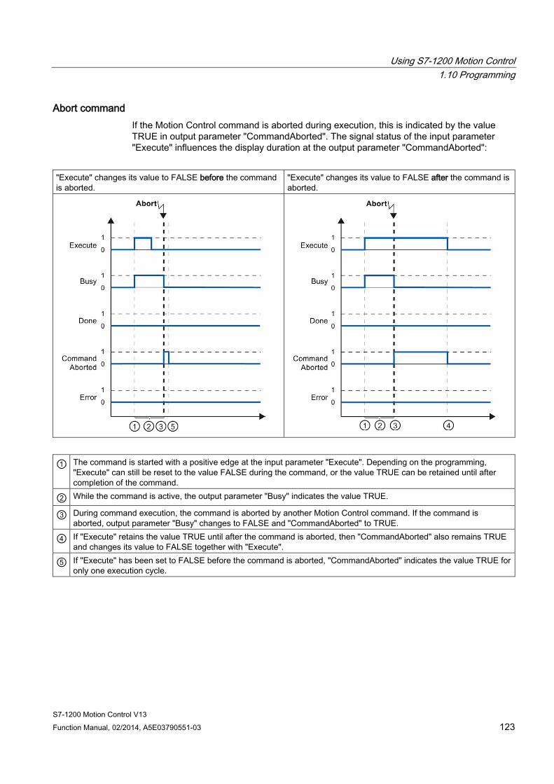
Using S7-1200 Motion Control 1.10 Programming
S7-1200 Motion Control V13 Function Manual, 02/2014, A5E03790551-03 123
Abort command If the Motion Control command is aborted during execution, this is indicated by the value TRUE in output parameter "CommandAborted". The signal status of the input parameter "Execute" influences the display duration at the output parameter "CommandAborted":
"Execute" changes its value to FALSE before the command is aborted.
"Execute" changes its value to FALSE after the command is aborted.
① The command is started with a positive edge at the input parameter "Execute". Depending on the programming, "Execute" can still be reset to the value FALSE during the command, or the value TRUE can be retained until after completion of the command.
② While the command is active, the output parameter "Busy" indicates the value TRUE.
③ During command execution, the command is aborted by another Motion Control command. If the command is aborted, output parameter "Busy" changes to FALSE and "CommandAborted" to TRUE.
④ If "Execute" retains the value TRUE until after the command is aborted, then "CommandAborted" also remains TRUE and changes its value to FALSE together with "Execute".
⑤ If "Execute" has been set to FALSE before the command is aborted, "CommandAborted" indicates the value TRUE for only one execution cycle.

Using S7-1200 Motion Control 1.10 Programming
S7-1200 Motion Control V13 124 Function Manual, 02/2014, A5E03790551-03
Error during command execution If an error occurs during execution of the Motion Control command, this is indicated by the value TRUE in the output parameter "Error". The signal status of the input parameter "Execute" influences the display duration at the output parameter "Error":
"Execute" changes its value to FALSE before the error occurs
"Execute" changes its value to FALSE after the error occurs
① The command is started with a positive edge at the input parameter "Execute". Depending on the programming, "Execute" can still be reset to the value FALSE during the command, or the value TRUE can be retained until after completion of the command.
② While the command is active, the output parameter "Busy" indicates the value TRUE.
③ An error occurred during command execution. When the error occurs, the output parameter "Busy" changes to FALSE and "Error" to TRUE.
④ If "Execute" retains the value TRUE until after the error occurs, then "Error" also remains TRUE and only changes its value to FALSE together with "Execute".
⑤ If "Execute" has been set to FALSE before the error occurs, "Error" indicates the value TRUE for only one execution cycle.
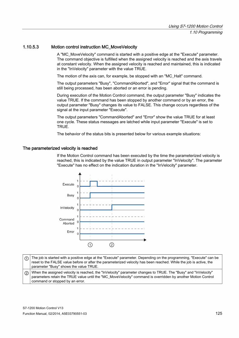
Using S7-1200 Motion Control 1.10 Programming
S7-1200 Motion Control V13 Function Manual, 02/2014, A5E03790551-03 125
1.10.5.3 Motion control instruction MC_MoveVelocity A "MC_MoveVelocity" command is started with a positive edge at the "Execute" parameter. The command objective is fulfilled when the assigned velocity is reached and the axis travels at constant velocity. When the assigned velocity is reached and maintained, this is indicated in the "InVelocity" parameter with the value TRUE.
The motion of the axis can, for example, be stopped with an "MC_Halt" command.
The output parameters "Busy", "CommandAborted", and "Error" signal that the command is still being processed, has been aborted or an error is pending.
During execution of the Motion Control command, the output parameter "Busy" indicates the value TRUE. If the command has been stopped by another command or by an error, the output parameter "Busy" changes its value to FALSE. This change occurs regardless of the signal at the input parameter "Execute".
The output parameters "CommandAborted" and "Error" show the value TRUE for at least one cycle. These status messages are latched while input parameter "Execute" is set to TRUE.
The behavior of the status bits is presented below for various example situations:
The parameterized velocity is reached If the Motion Control command has been executed by the time the parameterized velocity is reached, this is indicated by the value TRUE in output parameter "InVelocity". The parameter "Execute" has no effect on the indication duration in the "InVelocity" parameter.
① The job is started with a positive edge at the "Execute" parameter. Depending on the programming, "Execute" can be reset to the FALSE value before or after the parameterized velocity has been reached. While the job is active, the parameter "Busy" shows the value TRUE.
② When the assigned velocity is reached, the "InVelocity" parameter changes to TRUE. The "Busy" and "InVelocity" parameters retain the TRUE value until the "MC_MoveVelocity" command is overridden by another Motion Control command or stopped by an error.
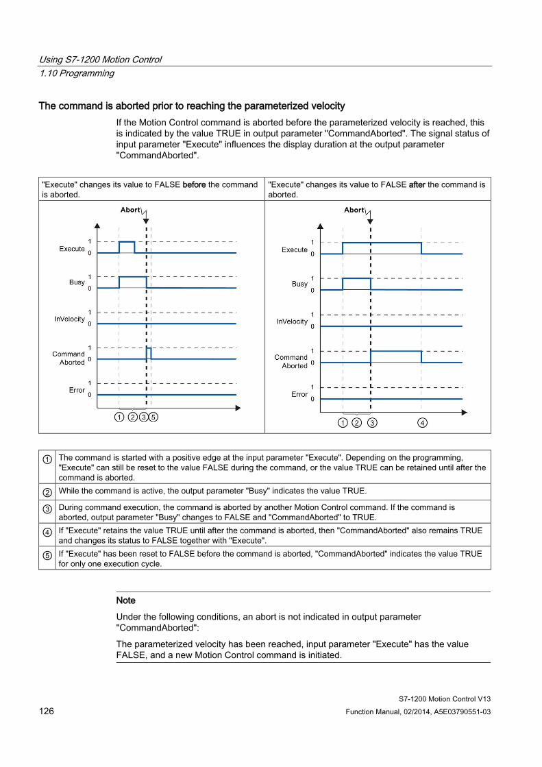
Using S7-1200 Motion Control 1.10 Programming
S7-1200 Motion Control V13 126 Function Manual, 02/2014, A5E03790551-03
The command is aborted prior to reaching the parameterized velocity If the Motion Control command is aborted before the parameterized velocity is reached, this is indicated by the value TRUE in output parameter "CommandAborted". The signal status of input parameter "Execute" influences the display duration at the output parameter "CommandAborted".
"Execute" changes its value to FALSE before the command is aborted.
"Execute" changes its value to FALSE after the command is aborted.
① The command is started with a positive edge at the input parameter "Execute". Depending on the programming, "Execute" can still be reset to the value FALSE during the command, or the value TRUE can be retained until after the command is aborted.
② While the command is active, the output parameter "Busy" indicates the value TRUE.
③ During command execution, the command is aborted by another Motion Control command. If the command is aborted, output parameter "Busy" changes to FALSE and "CommandAborted" to TRUE.
④ If "Execute" retains the value TRUE until after the command is aborted, then "CommandAborted" also remains TRUE and changes its status to FALSE together with "Execute".
⑤ If "Execute" has been reset to FALSE before the command is aborted, "CommandAborted" indicates the value TRUE for only one execution cycle.
Note
Under the following conditions, an abort is not indicated in output parameter "CommandAborted":
The parameterized velocity has been reached, input parameter "Execute" has the value FALSE, and a new Motion Control command is initiated.
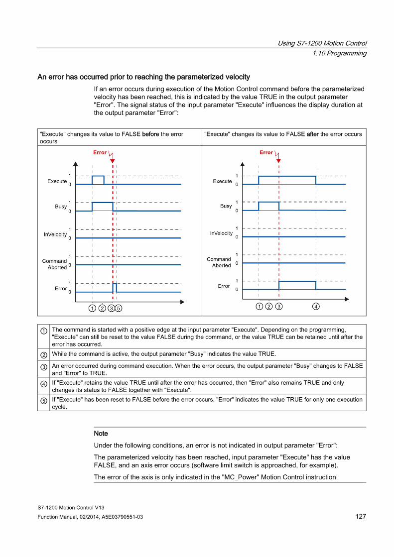
Using S7-1200 Motion Control 1.10 Programming
S7-1200 Motion Control V13 Function Manual, 02/2014, A5E03790551-03 127
An error has occurred prior to reaching the parameterized velocity If an error occurs during execution of the Motion Control command before the parameterized velocity has been reached, this is indicated by the value TRUE in the output parameter "Error". The signal status of the input parameter "Execute" influences the display duration at the output parameter "Error":
"Execute" changes its value to FALSE before the error occurs
"Execute" changes its value to FALSE after the error occurs
① The command is started with a positive edge at the input parameter "Execute". Depending on the programming, "Execute" can still be reset to the value FALSE during the command, or the value TRUE can be retained until after the error has occurred.
② While the command is active, the output parameter "Busy" indicates the value TRUE.
③ An error occurred during command execution. When the error occurs, the output parameter "Busy" changes to FALSE and "Error" to TRUE.
④ If "Execute" retains the value TRUE until after the error has occurred, then "Error" also remains TRUE and only changes its status to FALSE together with "Execute".
⑤ If "Execute" has been reset to FALSE before the error occurs, "Error" indicates the value TRUE for only one execution cycle.
Note
Under the following conditions, an error is not indicated in output parameter "Error":
The parameterized velocity has been reached, input parameter "Execute" has the value FALSE, and an axis error occurs (software limit switch is approached, for example).
The error of the axis is only indicated in the "MC_Power" Motion Control instruction.
Using S7-1200 Motion Control 1.10 Programming
S7-1200 Motion Control V13 128 Function Manual, 02/2014, A5E03790551-03
1.10.5.4 Motion control instruction MC_MoveJog The commands of Motion Control instruction "MC_MoveJog" implement a jog operation.
The motion control commands "MC_MoveJog" do not have a defined end. The command objective is fulfilled when the parameterized velocity is reached for the first time and the axis travels at constant velocity. When the parameterized velocity is reached, this is indicated by the value TRUE in output parameter "InVelocity".
The order is complete when input parameter "JogForward" or "JogBackward" has been set to the value FALSE and the axis has come to a standstill.
The output parameters "Busy", "CommandAborted", and "Error" signal that the command is still being processed, has been aborted or an error is pending.
During processing of the motion control command, the output parameter "Busy" indicates the value TRUE. If the command has been completed, aborted, or stopped by an error, the output parameter "Busy" changes its value to FALSE.
The output parameter "InVelocity" indicates the status TRUE, as long as the axis is moving at the parameterized velocity. The output parameters "CommandAborted" and "Error" indicate the status for at least one cycle. These status messages are latched as long as either input parameter "JogForward" or "JogBackward" is set to TRUE.

Using S7-1200 Motion Control 1.10 Programming
S7-1200 Motion Control V13 Function Manual, 02/2014, A5E03790551-03 129
The behavior of the status bits is presented below for various example situations:
The parameterized velocity is reached and maintained If the motion control command has been executed by the time the parameterized velocity is reached, this is indicated by the value TRUE in output parameter "InVelocity".
Jog mode is controlled by input parameter "JogForward" Jog mode is controlled by input parameter "JogBackward".
① The command is started with a positive edge at the input parameter "JogForward" or "JogBackward".
② While the command is active, the output parameter "Busy" indicates the value TRUE.
③ When the parameterized velocity is reached, the output parameter "InVelocity" changes to TRUE.
④ When the input parameter "JogForward" or "JogBackward" is reset to the value FALSE, the axis motion ends. The axis starts to decelerate. As a result, the axis no longer moves at constant velocity and the output parameter "InVelocity" changes its status to FALSE.
⑤ If the axis has come to a standstill, the motion control command is complete and the output parameter "Busy" changes its value to FALSE.
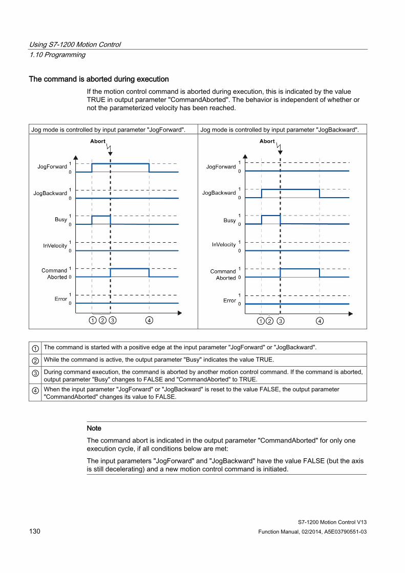
Using S7-1200 Motion Control 1.10 Programming
S7-1200 Motion Control V13 130 Function Manual, 02/2014, A5E03790551-03
The command is aborted during execution If the motion control command is aborted during execution, this is indicated by the value TRUE in output parameter "CommandAborted". The behavior is independent of whether or not the parameterized velocity has been reached.
Jog mode is controlled by input parameter "JogForward". Jog mode is controlled by input parameter "JogBackward".
① The command is started with a positive edge at the input parameter "JogForward" or "JogBackward".
② While the command is active, the output parameter "Busy" indicates the value TRUE.
③ During command execution, the command is aborted by another motion control command. If the command is aborted, output parameter "Busy" changes to FALSE and "CommandAborted" to TRUE.
④ When the input parameter "JogForward" or "JogBackward" is reset to the value FALSE, the output parameter "CommandAborted" changes its value to FALSE.
Note
The command abort is indicated in the output parameter "CommandAborted" for only one execution cycle, if all conditions below are met:
The input parameters "JogForward" and "JogBackward" have the value FALSE (but the axis is still decelerating) and a new motion control command is initiated.
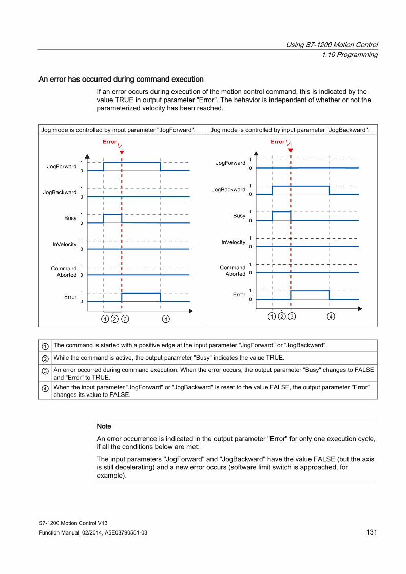
Using S7-1200 Motion Control 1.10 Programming
S7-1200 Motion Control V13 Function Manual, 02/2014, A5E03790551-03 131
An error has occurred during command execution If an error occurs during execution of the motion control command, this is indicated by the value TRUE in output parameter "Error". The behavior is independent of whether or not the parameterized velocity has been reached.
Jog mode is controlled by input parameter "JogForward". Jog mode is controlled by input parameter "JogBackward".
① The command is started with a positive edge at the input parameter "JogForward" or "JogBackward".
② While the command is active, the output parameter "Busy" indicates the value TRUE.
③ An error occurred during command execution. When the error occurs, the output parameter "Busy" changes to FALSE and "Error" to TRUE.
④ When the input parameter "JogForward" or "JogBackward" is reset to the value FALSE, the output parameter "Error" changes its value to FALSE.
Note
An error occurrence is indicated in the output parameter "Error" for only one execution cycle, if all the conditions below are met:
The input parameters "JogForward" and "JogBackward" have the value FALSE (but the axis is still decelerating) and a new error occurs (software limit switch is approached, for example).
Using S7-1200 Motion Control 1.10 Programming
S7-1200 Motion Control V13 132 Function Manual, 02/2014, A5E03790551-03
1.10.6 Error displays of the Motion Control statements The Motion Control instructions indicate any errors in motion control commands and the technology object at the output parameters "Error", "ErrorID" and "ErroInfo" of the Motion Control instructions.
Error display at output parameters "Error", "ErrorID" and "ErrorInfo" If the output parameter "Error" indicates the value TRUE, the complete command, or portions thereof, could not be executed. The cause of the error is indicated by the value in output parameter "ErrorID". Detailed information about the cause of the error is returned by the value in output parameter ErrorInfo. We distinguish between the following error classes for error indication: ● Operating error with axis stop (for example, "HW limit switch was approached")
Operating errors with axis stop are errors that occur during runtime of the user program. If the axis is in motion, it is stopped with the configured deceleration or emergency stop deceleration, depending on the error. The errors are indicated in the error-triggering Motion Control instruction and in the Motion Control instruction "MC_Power".
● Operating error without axis stop (for example, "Axis is not homed") Operating errors without axis stop are errors that occur during runtime of the user program. If the axis is in motion, the motion is continued. The errors are only indicated in the Motion Control instruction which triggers the error.
● Configuration error in Motion Control instruction (for example "Incorrect value in parameter "Velocity") Parameterization errors occur when incorrect information is specified in the input parameters of Motion Control instructions. If the axis is in motion, the motion is continued. The errors are only indicated in the Motion Control instruction which triggers the error.
● Configuration error on technology object "Axis" (for example, "Value for "Acceleration" is invalid") A configuration error exists if one or more parameters are incorrectly configured in the axis configuration or if editable configuration data have been modified incorrectly during runtime of the program. An axis in motion is stopped with the configured emergency stop deceleration. The error is indicated in the error-triggering Motion Control instruction and in Motion Control instruction "MC_Power".
● Configuration error on technology object "Command table" (for example "Value for "Velocity" is invalid") There is a configuration error if one or more parameters are incorrectly set in the axis command table or if programmable configuration data have been modified incorrectly during runtime of the program. If the axis is in motion, the motion is continued. The errors are only indicated in the "MC_CommandTable" Motion Control instruction.
● Internal error When an internal error occurs, the axis is stopped. The errors are indicated in the error-triggering Motion Control instruction and, in some cases, in the Motion Control instruction "MC_Power".
A detailed description of the ErrorIDs and ErrorInfos, as well as their remedies, is available in the Appendix (Page 154).
Using S7-1200 Motion Control 1.10 Programming
S7-1200 Motion Control V13 Function Manual, 02/2014, A5E03790551-03 133
See also Overview of the Motion Control statements (Page 114)
Creating a user program (Page 115)
Programming notes (Page 118)
Behavior of the Motion Control commands after POWER OFF and restart (Page 120)
Monitoring active commands (Page 121)
List of ErrorIDs and ErrorInfos (technology objects as of V4) (Page 154)
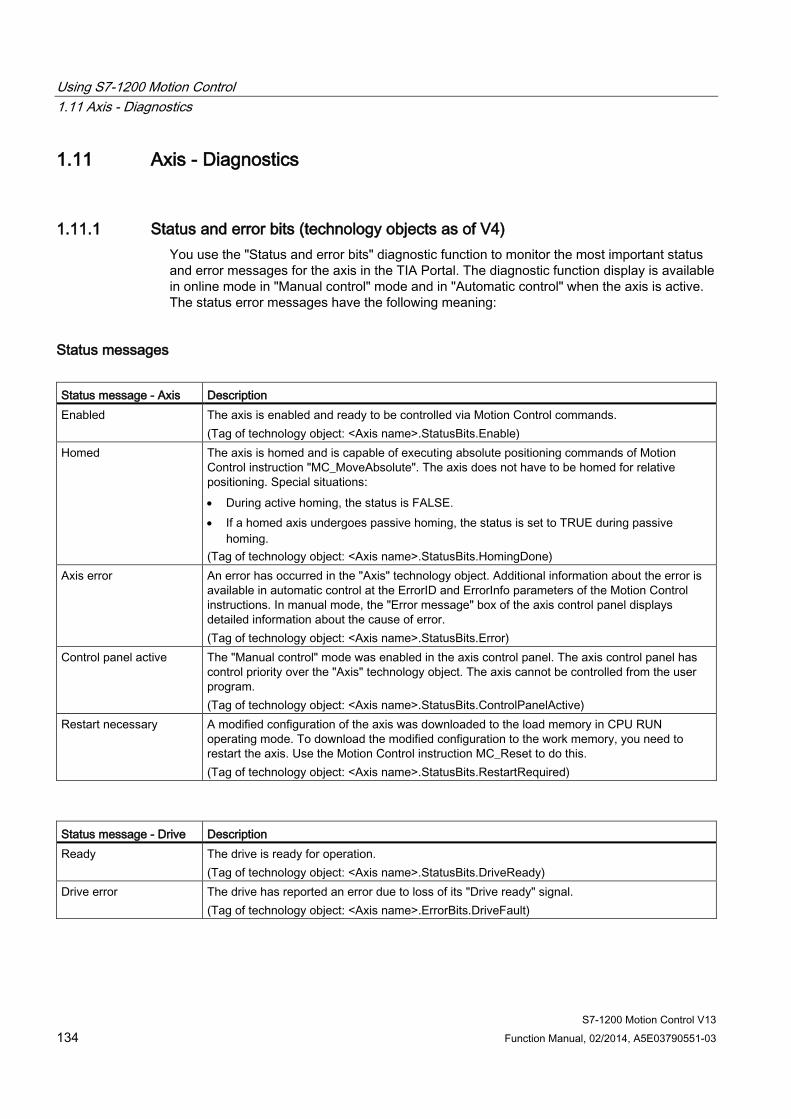
Using S7-1200 Motion Control 1.11 Axis - Diagnostics
S7-1200 Motion Control V13 134 Function Manual, 02/2014, A5E03790551-03
1.11 Axis - Diagnostics
1.11.1 Status and error bits (technology objects as of V4) You use the "Status and error bits" diagnostic function to monitor the most important status and error messages for the axis in the TIA Portal. The diagnostic function display is available in online mode in "Manual control" mode and in "Automatic control" when the axis is active. The status error messages have the following meaning:
Status messages Status message - Axis Description Enabled The axis is enabled and ready to be controlled via Motion Control commands.
(Tag of technology object: <Axis name>.StatusBits.Enable) Homed The axis is homed and is capable of executing absolute positioning commands of Motion
Control instruction "MC_MoveAbsolute". The axis does not have to be homed for relative positioning. Special situations: • During active homing, the status is FALSE. • If a homed axis undergoes passive homing, the status is set to TRUE during passive
homing. (Tag of technology object: <Axis name>.StatusBits.HomingDone)
Axis error An error has occurred in the "Axis" technology object. Additional information about the error is available in automatic control at the ErrorID and ErrorInfo parameters of the Motion Control instructions. In manual mode, the "Error message" box of the axis control panel displays detailed information about the cause of error. (Tag of technology object: <Axis name>.StatusBits.Error)
Control panel active The "Manual control" mode was enabled in the axis control panel. The axis control panel has control priority over the "Axis" technology object. The axis cannot be controlled from the user program. (Tag of technology object: <Axis name>.StatusBits.ControlPanelActive)
Restart necessary A modified configuration of the axis was downloaded to the load memory in CPU RUN operating mode. To download the modified configuration to the work memory, you need to restart the axis. Use the Motion Control instruction MC_Reset to do this. (Tag of technology object: <Axis name>.StatusBits.RestartRequired)
Status message - Drive Description Ready The drive is ready for operation.
(Tag of technology object: <Axis name>.StatusBits.DriveReady) Drive error The drive has reported an error due to loss of its "Drive ready" signal.
(Tag of technology object: <Axis name>.ErrorBits.DriveFault)

Using S7-1200 Motion Control 1.11 Axis - Diagnostics
S7-1200 Motion Control V13 Function Manual, 02/2014, A5E03790551-03 135
Status message - Motion Description Standstill The axis is at a standstill.
(Tag of technology object: <Axis name>.StatusBits.StandStill) Acceleration The axis accelerates.
(Tag of technology object: <Axis name>.StatusBits.Accelerating) Constant velocity The axis travels at constant velocity.
(Tag of technology object: <Axis name>.StatusBits.ConstantVelocity) Deceleration The axis decelerates (slows down).
(Tag of technology object: <Axis name>.StatusBits.Decelerating)
Status message - Motion type
Description
Positioning The axis executes a positioning command of the Motion Control instruction "MC_MoveAbsolute", "MC_MoveRelative" or the axis control panel. (Tag of technology object: <Axis name>.StatusBits.PositioningCommand)
Travel with velocity specification
The axis executes a command with velocity specification of the Motion Control instruction "MC_MoveVelocity", "MC_MoveJog" or the axis control panel. (Tag of technology object: <Axis name>.StatusBits.VelocityCommand)
Homing The axis executes a homing command of the Motion Control instruction "MC_Home" or the axis control panel. (Tag of technology object: <Axis name>.StatusBits.HomingCommand)
Command table active The axis is controlled by Motion Control instruction "MC_CommandTable". (Tag of technology object: <Axis name>.StatusBits.CommandTableActive)
Limit switch status messages Limit switch status message Description Lower SW limit switch has been reached
A software limit switch was reached or exceeded. (Tag of technology object: <Axis name>.StatusBits.SWLimitMinActive)
Upper SW limit switch has been reached
A hardware limit switch was reached or exceeded. (Tag of technology object: <Axis name>.StatusBits.SWLimitMaxActive)
Lower HW limit switch was reached
The lower hardware limit switch was reached or exceeded. (Tag of technology object: <Axis name>.StatusBits.HWLimitMinActive)
Upper HW limit switch was reached
The upper hardware limit switch was reached or exceeded. (Tag of technology object: <Axis name>.StatusBits.HWLimitMaxActive)
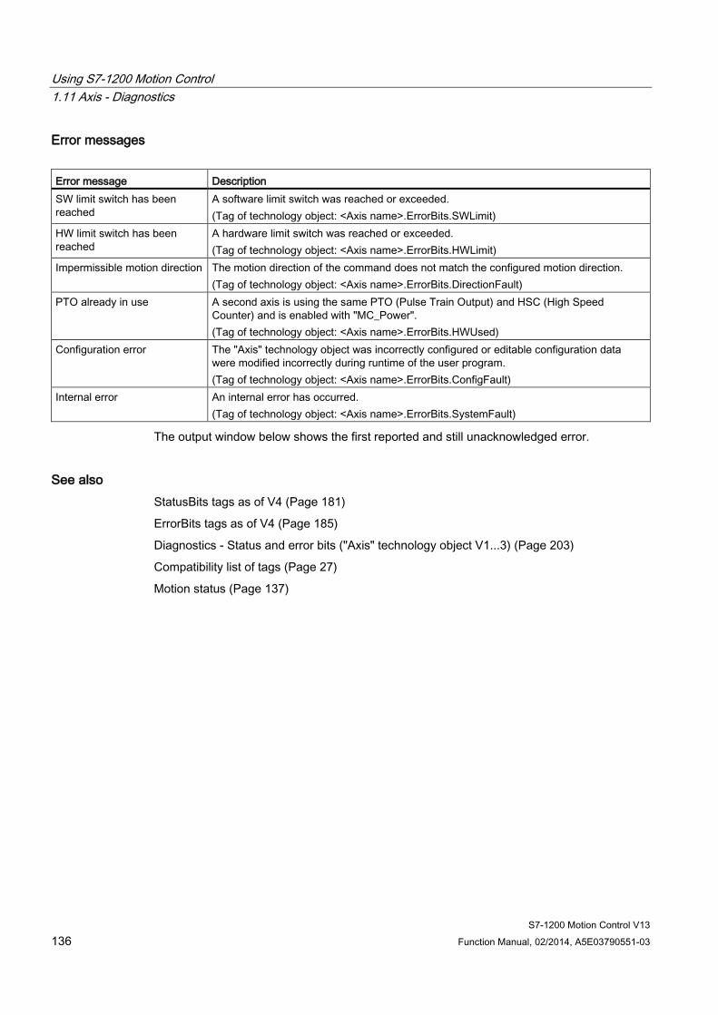
Using S7-1200 Motion Control 1.11 Axis - Diagnostics
S7-1200 Motion Control V13 136 Function Manual, 02/2014, A5E03790551-03
Error messages Error message Description SW limit switch has been reached
A software limit switch was reached or exceeded. (Tag of technology object: <Axis name>.ErrorBits.SWLimit)
HW limit switch has been reached
A hardware limit switch was reached or exceeded. (Tag of technology object: <Axis name>.ErrorBits.HWLimit)
Impermissible motion direction The motion direction of the command does not match the configured motion direction. (Tag of technology object: <Axis name>.ErrorBits.DirectionFault)
PTO already in use A second axis is using the same PTO (Pulse Train Output) and HSC (High Speed Counter) and is enabled with "MC_Power". (Tag of technology object: <Axis name>.ErrorBits.HWUsed)
Configuration error The "Axis" technology object was incorrectly configured or editable configuration data were modified incorrectly during runtime of the user program. (Tag of technology object: <Axis name>.ErrorBits.ConfigFault)
Internal error An internal error has occurred. (Tag of technology object: <Axis name>.ErrorBits.SystemFault)
The output window below shows the first reported and still unacknowledged error.
See also StatusBits tags as of V4 (Page 181)
ErrorBits tags as of V4 (Page 185)
Diagnostics - Status and error bits ("Axis" technology object V1...3) (Page 203)
Compatibility list of tags (Page 27)
Motion status (Page 137)
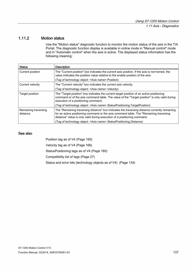
Using S7-1200 Motion Control 1.11 Axis - Diagnostics
S7-1200 Motion Control V13 Function Manual, 02/2014, A5E03790551-03 137
1.11.2 Motion status Use the "Motion status" diagnostic function to monitor the motion status of the axis in the TIA Portal. The diagnostic function display is available in online mode in "Manual control" mode and in "Automatic control" when the axis is active. The displayed status information has the following meaning:
Status Description Current position The "Current position" box indicates the current axis position. If the axis is not homed, the
value indicates the position value relative to the enable position of the axis. (Tag of technology object: <Axis name>.Position)
Current velocity The "Current velocity" box indicates the current axis velocity. (Tag of technology object: <Axis name>.Velocity)
Target position The "Target position" box indicates the current target position of an active positioning command or of the axis command table. The value of the "Target position" is only valid during execution of a positioning command. (Tag of technology object: <Axis name>.StatusPositioning.TargetPosition)
Remaining traversing distance
The "Remaining traversing distance" box indicates the traversing distance currently remaining for an active positioning command or the axis command table. The "Remaining traversing distance" value is only valid during execution of a positioning command. (Tag of technology object: <Axis name>.StatusPositioning.Distance)
See also Position tag as of V4 (Page 165)
Velocity tag as of V4 (Page 166)
StatusPositioning tags as of V4 (Page 180)
Compatibility list of tags (Page 27)
Status and error bits (technology objects as of V4) (Page 134)

Using S7-1200 Motion Control 1.11 Axis - Diagnostics
S7-1200 Motion Control V13 138 Function Manual, 02/2014, A5E03790551-03
1.11.3 Dynamics settings Use the "Dynamics settings" diagnostic function to monitor the dynamic limits of the axis in the TIA Portal. The diagnostic function display is available in online mode in "Manual control" mode and in "Automatic control" when the axis is active. The displayed status information has the following meaning:
Dynamic limit Description Acceleration The "Acceleration" box indicates the currently configured acceleration of the axis.
(Tag of technology object: <Axis name>.DynamicDefaults.Acceleration) Deceleration The "Deceleration" box indicates the currently configured deceleration of the axis.
(Tag of technology object: <Axis name>.DynamicDefaults.Deceleration) Emergency stop deceleration
The "Emergency stop deceleration" box indicates the currently configured emergency stop deceleration of the axis. (Tag of technology object: <Axis name>.DynamicDefaults.EmergencyDeceleration)
Jerk (axis technology object as of V2)
The "Velocity" box indicates the current axis step velocity configured. (Tag of technology object: <Axis name>.DynamicDefaults.Jerk)
See also DynamicDefaults tags as of V4 (Page 175)
Compatibility list of tags (Page 27)
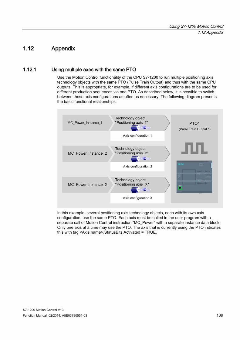
Using S7-1200 Motion Control 1.12 Appendix
S7-1200 Motion Control V13 Function Manual, 02/2014, A5E03790551-03 139
1.12 Appendix
1.12.1 Using multiple axes with the same PTO Use the Motion Control functionality of the CPU S7-1200 to run multiple positioning axis technology objects with the same PTO (Pulse Train Output) and thus with the same CPU outputs. This is appropriate, for example, if different axis configurations are to be used for different production sequences via one PTO. As described below, it is possible to switch between these axis configurations as often as necessary. The following diagram presents the basic functional relationships:
In this example, several positioning axis technology objects, each with its own axis configuration, use the same PTO. Each axis must be called in the user program with a separate call of Motion Control instruction "MC_Power" with a separate instance data block. Only one axis at a time may use the PTO. The axis that is currently using the PTO indicates this with tag <Axis name>.StatusBits.Activated = TRUE.
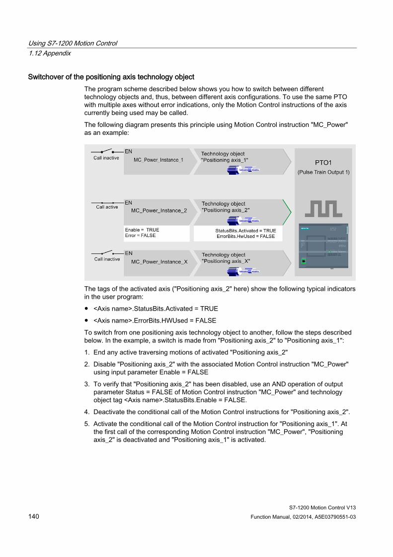
Using S7-1200 Motion Control 1.12 Appendix
S7-1200 Motion Control V13 140 Function Manual, 02/2014, A5E03790551-03
Switchover of the positioning axis technology object The program scheme described below shows you how to switch between different technology objects and, thus, between different axis configurations. To use the same PTO with multiple axes without error indications, only the Motion Control instructions of the axis currently being used may be called.
The following diagram presents this principle using Motion Control instruction "MC_Power" as an example:
The tags of the activated axis ("Positioning axis_2" here) show the following typical indicators in the user program:
● <Axis name>.StatusBits.Activated = TRUE
● <Axis name>.ErrorBits.HWUsed = FALSE
To switch from one positioning axis technology object to another, follow the steps described below. In the example, a switch is made from "Positioning axis_2" to "Positioning axis_1":
1. End any active traversing motions of activated "Positioning axis_2"
2. Disable "Positioning axis_2" with the associated Motion Control instruction "MC_Power" using input parameter Enable = FALSE
3. To verify that "Positioning axis_2" has been disabled, use an AND operation of output parameter Status = FALSE of Motion Control instruction "MC_Power" and technology object tag <Axis name>.StatusBits.Enable = FALSE.
4. Deactivate the conditional call of the Motion Control instructions for "Positioning axis_2".
5. Activate the conditional call of the Motion Control instruction for "Positioning axis_1". At the first call of the corresponding Motion Control instruction "MC_Power", "Positioning axis_2" is deactivated and "Positioning axis_1" is activated.
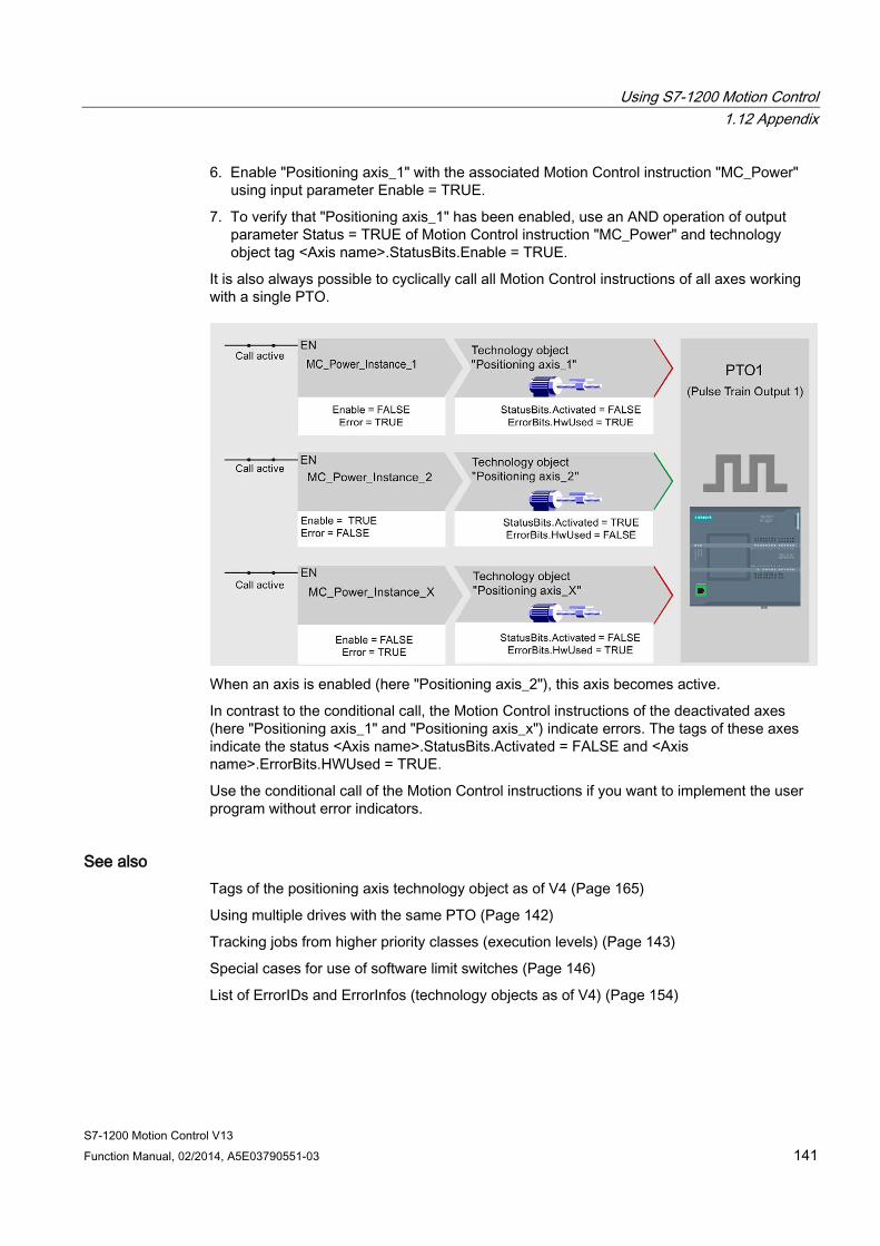
Using S7-1200 Motion Control 1.12 Appendix
S7-1200 Motion Control V13 Function Manual, 02/2014, A5E03790551-03 141
6. Enable "Positioning axis_1" with the associated Motion Control instruction "MC_Power" using input parameter Enable = TRUE.
7. To verify that "Positioning axis_1" has been enabled, use an AND operation of output parameter Status = TRUE of Motion Control instruction "MC_Power" and technology object tag <Axis name>.StatusBits.Enable = TRUE.
It is also always possible to cyclically call all Motion Control instructions of all axes working with a single PTO.
When an axis is enabled (here "Positioning axis_2"), this axis becomes active.
In contrast to the conditional call, the Motion Control instructions of the deactivated axes (here "Positioning axis_1" and "Positioning axis_x") indicate errors. The tags of these axes indicate the status <Axis name>.StatusBits.Activated = FALSE and <Axis name>.ErrorBits.HWUsed = TRUE.
Use the conditional call of the Motion Control instructions if you want to implement the user program without error indicators.
See also Tags of the positioning axis technology object as of V4 (Page 165)
Using multiple drives with the same PTO (Page 142)
Tracking jobs from higher priority classes (execution levels) (Page 143)
Special cases for use of software limit switches (Page 146)
List of ErrorIDs and ErrorInfos (technology objects as of V4) (Page 154)
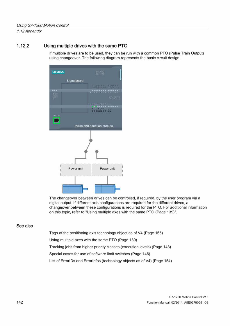
Using S7-1200 Motion Control 1.12 Appendix
S7-1200 Motion Control V13 142 Function Manual, 02/2014, A5E03790551-03
1.12.2 Using multiple drives with the same PTO If multiple drives are to be used, they can be run with a common PTO (Pulse Train Output) using changeover. The following diagram represents the basic circuit design:
The changeover between drives can be controlled, if required, by the user program via a digital output. If different axis configurations are required for the different drives, a changeover between these configurations is required for the PTO. For additional information on this topic, refer to "Using multiple axes with the same PTO (Page 139)".
See also Tags of the positioning axis technology object as of V4 (Page 165)
Using multiple axes with the same PTO (Page 139)
Tracking jobs from higher priority classes (execution levels) (Page 143)
Special cases for use of software limit switches (Page 146)
List of ErrorIDs and ErrorInfos (technology objects as of V4) (Page 154)
Using S7-1200 Motion Control 1.12 Appendix
S7-1200 Motion Control V13 Function Manual, 02/2014, A5E03790551-03 143
1.12.3 Tracking jobs from higher priority classes (execution levels) Depending on the application, it may be necessary to start Motion Control commands (for example, interrupt-controlled) in a higher priority class (execution level).
The Motion Control instructions must be called at short intervals for status monitoring. Motion Control commands cannot be sufficiently closely monitored if the higher priority Motion Control commands are called only once or at too great an interval. Tracking in such cases can be carried out in the cycle OB. An instance data block that is not currently being utilized must be available for each start of a higher priority Motion Control command. Refer to the following flow chart to see how you start Motion Control commands in a higher priority class (for example, hardware interrupt OB) and continue tracking in the program cycle OB:
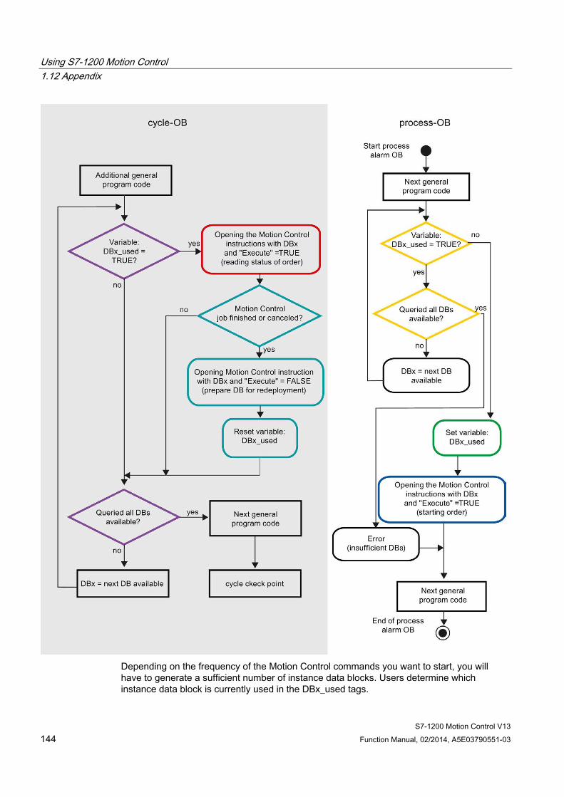
Using S7-1200 Motion Control 1.12 Appendix
S7-1200 Motion Control V13 144 Function Manual, 02/2014, A5E03790551-03
Depending on the frequency of the Motion Control commands you want to start, you will have to generate a sufficient number of instance data blocks. Users determine which instance data block is currently used in the DBx_used tags.

Using S7-1200 Motion Control 1.12 Appendix
S7-1200 Motion Control V13 Function Manual, 02/2014, A5E03790551-03 145
Start of Motion Control command in the hardware interrupt OB Binary queries of the DBx_used tags (orange) are used to find an instance data block not currently in use. If such an instance data block is found, the utilized instance data block is marked as "used" (green) and the Motion Control command is started with this instance data block (blue).
Any other program sections of the hardware interrupt OB are then executed, followed by a return to the program cycle OB.
Tracking of started Motion Control commands in the program cycle OB All instance data blocks available in the cycle OB are checked to determine if they are currently in use by means of the DBx_used tag (violet).
If an instance data block is in use (Motion Control command is being processed), the Motion Control instruction with this instance data block and input parameter Execute = TRUE is called to read out the status messages (red).
If the command is complete or has been aborted, the following actions are taken next (blue green):
● Call of Motion Control instruction with input parameter Execute = FALSE
● Resetting the DBx_used tag
This completes the command tracking, and the instance data block is now available for use again.
See also Tags of the positioning axis technology object as of V4 (Page 165)
Using multiple axes with the same PTO (Page 139)
Using multiple drives with the same PTO (Page 142)
Special cases for use of software limit switches (Page 146)
List of ErrorIDs and ErrorInfos (technology objects as of V4) (Page 154)
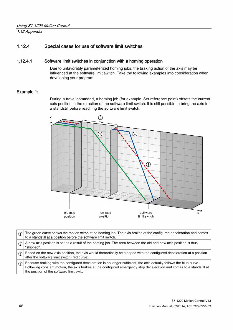
Using S7-1200 Motion Control 1.12 Appendix
S7-1200 Motion Control V13 146 Function Manual, 02/2014, A5E03790551-03
1.12.4 Special cases for use of software limit switches
1.12.4.1 Software limit switches in conjunction with a homing operation Due to unfavorably parameterized homing jobs, the braking action of the axis may be influenced at the software limit switch. Take the following examples into consideration when developing your program.
Example 1: During a travel command, a homing job (for example, Set reference point) offsets the current axis position in the direction of the software limit switch. It is still possible to bring the axis to a standstill before reaching the software limit switch:
① The green curve shows the motion without the homing job. The axis brakes at the configured deceleration and comes to a standstill at a position before the software limit switch.
② A new axis position is set as a result of the homing job. The area between the old and new axis position is thus "skipped".
③ Based on the new axis position, the axis would theoretically be stopped with the configured deceleration at a position after the software limit switch (red curve).
④ Because braking with the configured deceleration is no longer sufficient, the axis actually follows the blue curve. Following constant motion, the axis brakes at the configured emergency stop deceleration and comes to a standstill at the position of the software limit switch.
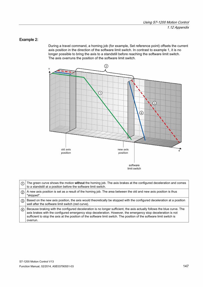
Using S7-1200 Motion Control 1.12 Appendix
S7-1200 Motion Control V13 Function Manual, 02/2014, A5E03790551-03 147
Example 2: During a travel command, a homing job (for example, Set reference point) offsets the current axis position in the direction of the software limit switch. In contrast to example 1, it is no longer possible to bring the axis to a standstill before reaching the software limit switch. The axis overruns the position of the software limit switch.
① The green curve shows the motion without the homing job. The axis brakes at the configured deceleration and comes to a standstill at a position before the software limit switch.
② A new axis position is set as a result of the homing job. The area between the old and new axis position is thus "skipped".
③ Based on the new axis position, the axis would theoretically be stopped with the configured deceleration at a position well after the software limit switch (red curve).
④ Because braking with the configured deceleration is no longer sufficient, the axis actually follows the blue curve. The axis brakes with the configured emergency stop deceleration. However, the emergency stop deceleration is not sufficient to stop the axis at the position of the software limit switch. The position of the software limit switch is overrun.
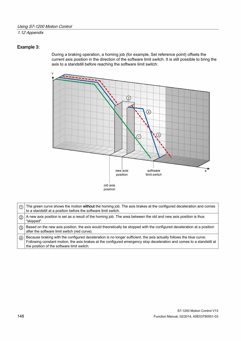
Using S7-1200 Motion Control 1.12 Appendix
S7-1200 Motion Control V13 148 Function Manual, 02/2014, A5E03790551-03
Example 3: During a braking operation, a homing job (for example, Set reference point) offsets the current axis position in the direction of the software limit switch. It is still possible to bring the axis to a standstill before reaching the software limit switch:
① The green curve shows the motion without the homing job. The axis brakes at the configured deceleration and comes to a standstill at a position before the software limit switch.
② A new axis position is set as a result of the homing job. The area between the old and new axis position is thus "skipped".
③ Based on the new axis position, the axis would theoretically be stopped with the configured deceleration at a position after the software limit switch (red curve).
④ Because braking with the configured deceleration is no longer sufficient, the axis actually follows the blue curve. Following constant motion, the axis brakes at the configured emergency stop deceleration and comes to a standstill at the position of the software limit switch.

Using S7-1200 Motion Control 1.12 Appendix
S7-1200 Motion Control V13 Function Manual, 02/2014, A5E03790551-03 149
Example 4: During a braking operation, a homing job (for example, Set reference point) offsets the current axis position in the direction of the software limit switch. In contrast to example 3, it is no longer possible to bring the axis to a standstill before reaching the software limit switch. The axis overruns the position of the software limit switch.
① The green curve shows the motion without the homing job. The axis brakes at the configured deceleration and comes
to a standstill at a position before the software limit switch.
② A new axis position is set as a result of the homing job. The area between the old and new axis position is thus "skipped".
③ Based on the new axis position, the axis would theoretically be stopped with the configured deceleration at a position well after the software limit switch (red curve).
④ Because braking with the configured deceleration is no longer sufficient, the axis actually follows the blue curve. The axis brakes with the configured emergency stop deceleration. However, the emergency stop deceleration is not sufficient to stop the axis at the position of the software limit switch. The position of the software limit switch is overrun.
See also Software limit switches and software limit switch position changes. (Page 150)
Software limit switches in conjunction with dynamic changes (Page 151)
Behavior of axis when position limits is tripped (Page 47)
Using S7-1200 Motion Control 1.12 Appendix
S7-1200 Motion Control V13 150 Function Manual, 02/2014, A5E03790551-03
1.12.4.2 Software limit switches and software limit switch position changes. An incorrect change in the position of the software limit switch during the runtime of the user program can abruptly reduce the distance between the current axis position and the position of the software limit switch.
The axis response is similar to that described in Software limit switches in conjunction with a homing operation (Page 146).
See also Software limit switches in conjunction with a homing operation (Page 146)
Software limit switches in conjunction with dynamic changes (Page 151)
Behavior of axis when position limits is tripped (Page 47)
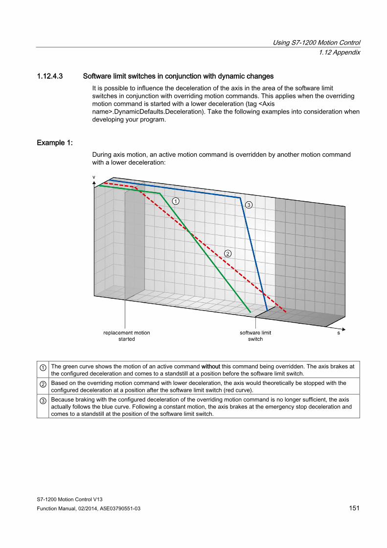
Using S7-1200 Motion Control 1.12 Appendix
S7-1200 Motion Control V13 Function Manual, 02/2014, A5E03790551-03 151
1.12.4.3 Software limit switches in conjunction with dynamic changes It is possible to influence the deceleration of the axis in the area of the software limit switches in conjunction with overriding motion commands. This applies when the overriding motion command is started with a lower deceleration (tag <Axis name>.DynamicDefaults.Deceleration). Take the following examples into consideration when developing your program.
Example 1: During axis motion, an active motion command is overridden by another motion command with a lower deceleration:
① The green curve shows the motion of an active command without this command being overridden. The axis brakes at the configured deceleration and comes to a standstill at a position before the software limit switch.
② Based on the overriding motion command with lower deceleration, the axis would theoretically be stopped with the configured deceleration at a position after the software limit switch (red curve).
③ Because braking with the configured deceleration of the overriding motion command is no longer sufficient, the axis actually follows the blue curve. Following a constant motion, the axis brakes at the emergency stop deceleration and comes to a standstill at the position of the software limit switch.
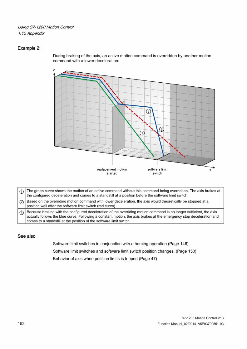
Using S7-1200 Motion Control 1.12 Appendix
S7-1200 Motion Control V13 152 Function Manual, 02/2014, A5E03790551-03
Example 2: During braking of the axis, an active motion command is overridden by another motion command with a lower deceleration:
① The green curve shows the motion of an active command without this command being overridden. The axis brakes at the configured deceleration and comes to a standstill at a position before the software limit switch.
② Based on the overriding motion command with lower deceleration, the axis would theoretically be stopped at a position well after the software limit switch (red curve).
③ Because braking with the configured deceleration of the overriding motion command is no longer sufficient, the axis actually follows the blue curve. Following a constant motion, the axis brakes at the emergency stop deceleration and comes to a standstill at the position of the software limit switch.
See also Software limit switches in conjunction with a homing operation (Page 146)
Software limit switches and software limit switch position changes. (Page 150)
Behavior of axis when position limits is tripped (Page 47)
Using S7-1200 Motion Control 1.12 Appendix
S7-1200 Motion Control V13 Function Manual, 02/2014, A5E03790551-03 153
1.12.5 Reducing velocity for a short positioning duration The CPU can reduce the velocity of a positioning command when the planned positioning duration is < 2 ms.
The velocity of command execution will then be reduced for the entire duration. The reduced velocity (pulses per s) is calculated as follows:
● Reduced velocity = Number of pulses to be output * 500Hz
Velocity is not reduced if the planned positioning duration is >= 2 ms.
1.12.6 Dynamic adjustment of start/stop velocity The configuration of your velocity limits (start/stop velocity and maximum velocity), the dynamic values (acceleration, deceleration and jerk) and the target speed of the traversing command may under certain circumstances result in the start/stop velocity being dynamically adjusted by the CPU.
This is for example the case when, due to a low configured start/stop velocity, the time required for the first pulses would be longer than that possible for the entire acceleration. The first pulse is in these cases output at a greater velocity than the configured start/stop velocity. The subsequent pulses are also dynamically adjusted to ensure the acceleration process can be completed in the specified time.
Ensure in the event of any pulse loss that the hardware (drive) you use is adjusted to this situation, or change the dynamic settings of your axis to avoid dynamic adjustment of the start/stop velocity.

Using S7-1200 Motion Control 1.12 Appendix
S7-1200 Motion Control V13 154 Function Manual, 02/2014, A5E03790551-03
1.12.7 List of ErrorIDs and ErrorInfos (technology objects as of V4) The following table lists all ErrorIDs and ErrorInfos that can be indicated in Motion Control instructions. In addition to the cause of the error, remedies for eliminating the error are also listed:
Operating error with axis stop ErrorID ErrorInfo Description Remedy 16#8000 Drive error, loss of "Drive ready" 16#0001 - Acknowledge error with instruction "MC_Reset";
provide drive signal; restart command, if necessary
16#8001 Lower SW limit switch has been tripped 16#000E The position of the lower SW limit switch was
reached with the currently configured deceleration
Acknowledge the error with instruction "MC_Reset"; use a motion command to move the axis in the positive direction out of the range of the SW limit switch 16#000F The position of the lower SW limit switch was
reached with the emergency stop deceleration 16#0010 The position of the lower SW limit switch was
exceeded with the emergency stop deceleration
16#8002 Upper SW limit switch has been tripped 16#000E The position of the upper SW limit switch was
reached with the currently configured deceleration
Acknowledge the error with instruction "MC_Reset"; use a motion command to move the axis in the negative direction out of the range of the SW limit switch 16#000F The position of the upper SW limit switch was
reached with the emergency stop deceleration 16#0010 The position of the upper SW limit switch was
exceeded with the emergency stop deceleration
16#8003 Lower HW limit switch was reached 16#000E The lower HW limit switch was reached. The
axis was stopped with the emergency stop deceleration. (During an active homing procedure, the homing switch was not found)
Acknowledge the error for an enabled axis with instruction "MC_Reset"; use a motion command to move the axis in the positive direction out of the range of the HW limit switch.
16#8004 Upper HW limit switch was reached 16#000E The upper HW limit switch has been reached.
The axis was stopped with the emergency stop deceleration. (During an active homing procedure, the homing switch was not found)
Acknowledge the error for an enabled axis with instruction "MC_Reset"; use a motion command to move the axis in the negative direction out of the range of the HW limit switch.
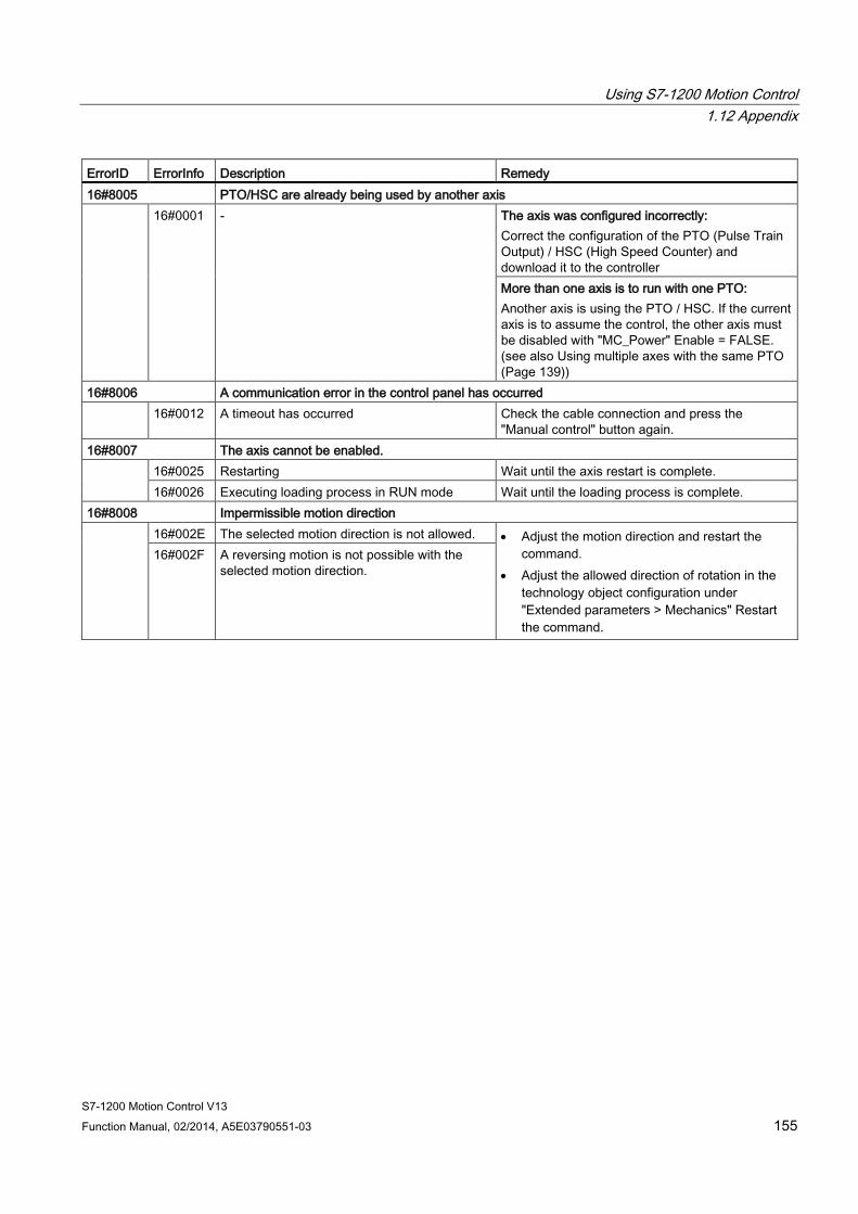
Using S7-1200 Motion Control 1.12 Appendix
S7-1200 Motion Control V13 Function Manual, 02/2014, A5E03790551-03 155
ErrorID ErrorInfo Description Remedy 16#8005 PTO/HSC are already being used by another axis 16#0001 - The axis was configured incorrectly:
Correct the configuration of the PTO (Pulse Train Output) / HSC (High Speed Counter) and download it to the controller More than one axis is to run with one PTO: Another axis is using the PTO / HSC. If the current axis is to assume the control, the other axis must be disabled with "MC_Power" Enable = FALSE. (see also Using multiple axes with the same PTO (Page 139))
16#8006 A communication error in the control panel has occurred 16#0012 A timeout has occurred Check the cable connection and press the
"Manual control" button again. 16#8007 The axis cannot be enabled.
16#0025 Restarting Wait until the axis restart is complete. 16#0026 Executing loading process in RUN mode Wait until the loading process is complete.
16#8008 Impermissible motion direction 16#002E The selected motion direction is not allowed. • Adjust the motion direction and restart the
command. • Adjust the allowed direction of rotation in the
technology object configuration under "Extended parameters > Mechanics" Restart the command.
16#002F A reversing motion is not possible with the selected motion direction.
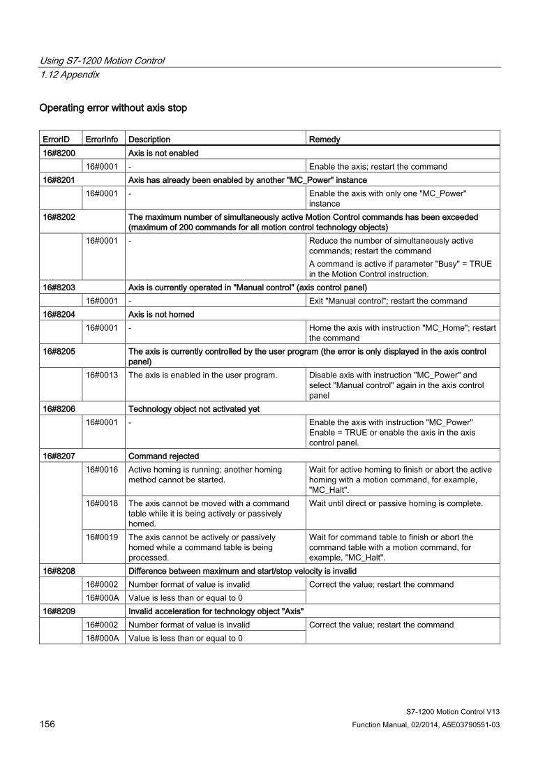
Using S7-1200 Motion Control 1.12 Appendix
S7-1200 Motion Control V13 156 Function Manual, 02/2014, A5E03790551-03
Operating error without axis stop ErrorID ErrorInfo Description Remedy 16#8200 Axis is not enabled 16#0001 - Enable the axis; restart the command 16#8201 Axis has already been enabled by another "MC_Power" instance 16#0001 - Enable the axis with only one "MC_Power"
instance 16#8202 The maximum number of simultaneously active Motion Control commands has been exceeded
(maximum of 200 commands for all motion control technology objects) 16#0001 - Reduce the number of simultaneously active
commands; restart the command A command is active if parameter "Busy" = TRUE in the Motion Control instruction.
16#8203 Axis is currently operated in "Manual control" (axis control panel) 16#0001 - Exit "Manual control"; restart the command 16#8204 Axis is not homed 16#0001 - Home the axis with instruction "MC_Home"; restart
the command 16#8205 The axis is currently controlled by the user program (the error is only displayed in the axis control
panel) 16#0013 The axis is enabled in the user program. Disable axis with instruction "MC_Power" and
select "Manual control" again in the axis control panel
16#8206 Technology object not activated yet 16#0001 - Enable the axis with instruction "MC_Power"
Enable = TRUE or enable the axis in the axis control panel.
16#8207 Command rejected 16#0016 Active homing is running; another homing
method cannot be started. Wait for active homing to finish or abort the active homing with a motion command, for example, "MC_Halt".
16#0018 The axis cannot be moved with a command table while it is being actively or passively homed.
Wait until direct or passive homing is complete.
16#0019 The axis cannot be actively or passively homed while a command table is being processed.
Wait for command table to finish or abort the command table with a motion command, for example, "MC_Halt".
16#8208 Difference between maximum and start/stop velocity is invalid 16#0002 Number format of value is invalid Correct the value; restart the command
16#000A Value is less than or equal to 0 16#8209 Invalid acceleration for technology object "Axis" 16#0002 Number format of value is invalid Correct the value; restart the command
16#000A Value is less than or equal to 0
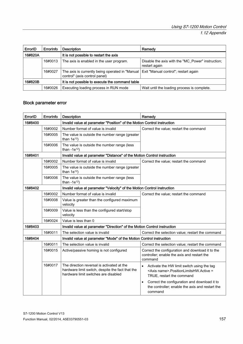
Using S7-1200 Motion Control 1.12 Appendix
S7-1200 Motion Control V13 Function Manual, 02/2014, A5E03790551-03 157
ErrorID ErrorInfo Description Remedy 16#820A It is not possible to restart the axis
16#0013 The axis is enabled in the user program. Disable the axis with the "MC_Power" instruction; restart again
16#0027 The axis is currently being operated in "Manual control" (axis control panel)
Exit "Manual control"; restart again
16#820B It is not possible to execute the command table 16#0026 Executing loading process in RUN mode Wait until the loading process is complete.
Block parameter error ErrorID ErrorInfo Description Remedy 16#8400 Invalid value at parameter "Position" of the Motion Control instruction 16#0002 Number format of value is invalid Correct the value; restart the command
16#0005 The value is outside the number range (greater than 1e12)
16#0006 The value is outside the number range (less than -1e12)
16#8401 Invalid value at parameter "Distance" of the Motion Control instruction 16#0002 Number format of value is invalid Correct the value; restart the command
16#0005 The value is outside the number range (greater than 1e12)
16#0006 The value is outside the number range (less than -1e12)
16#8402 Invalid value at parameter "Velocity" of the Motion Control instruction 16#0002 Number format of value is invalid Correct the value; restart the command
16#0008 Value is greater than the configured maximum velocity
16#0009 Value is less than the configured start/stop velocity
16#0024 Value is less than 0 16#8403 Invalid value at parameter "Direction" of the Motion Control instruction 16#0011 The selection value is invalid Correct the selection value; restart the command 16#8404 Invalid value at parameter "Mode" of the Motion Control instruction 16#0011 The selection value is invalid Correct the selection value; restart the command
16#0015 Active/passive homing is not configured Correct the configuration and download it to the controller; enable the axis and restart the command
16#0017 The direction reversal is activated at the hardware limit switch, despite the fact that the hardware limit switches are disabled
• Activate the HW limit switch using the tag <Axis name>.PositionLimitsHW.Active = TRUE, restart the command
• Correct the configuration and download it to the controller; enable the axis and restart the command
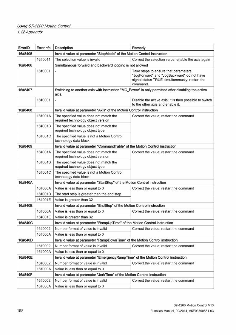
Using S7-1200 Motion Control 1.12 Appendix
S7-1200 Motion Control V13 158 Function Manual, 02/2014, A5E03790551-03
ErrorID ErrorInfo Description Remedy 16#8405 Invalid value at parameter "StopMode" of the Motion Control instruction 16#0011 The selection value is invalid Correct the selection value; enable the axis again 16#8406 Simultaneous forward and backward jogging is not allowed 16#0001 - Take steps to ensure that parameters
"JogForward" and "JogBackward" do not have signal status TRUE simultaneously; restart the command.
16#8407 Switching to another axis with instruction "MC_Power" is only permitted after disabling the active axis.
16#0001 - Disable the active axis; it is then possible to switch to the other axis and enable it.
16#8408 Invalid value at parameter "Axis" of the Motion Control instruction 16#001A The specified value does not match the
required technology object version Correct the value; restart the command
16#001B The specified value does not match the required technology object type
16#001C The specified value is not a Motion Control technology data block
16#8409 Invalid value at parameter "CommandTable" of the Motion Control instruction 16#001A The specified value does not match the
required technology object version Correct the value; restart the command
16#001B The specified value does not match the required technology object type
16#001C The specified value is not a Motion Control technology data block
16#840A Invalid value at parameter "StartStep" of the Motion Control instruction 16#000A Value is less than or equal to 0 Correct the value; restart the command
16#001D The start step is greater than the end step 16#001E Value is greater than 32
16#840B Invalid value at parameter "EndStep" of the Motion Control instruction 16#000A Value is less than or equal to 0 Correct the value; restart the command
16#001E Value is greater than 32 16#840C Invalid value at parameter "RampUpTime" of the Motion Control instruction 16#0002 Number format of value is invalid Correct the value; restart the command
16#000A Value is less than or equal to 0 16#840D Invalid value at parameter "RampDownTime" of the Motion Control instruction 16#0002 Number format of value is invalid Correct the value; restart the command
16#000A Value is less than or equal to 0 16#840E Invalid value at parameter "EmergencyRampTime" of the Motion Control instruction 16#0002 Number format of value is invalid Correct the value; restart the command
16#000A Value is less than or equal to 0 16#840F Invalid value at parameter "JerkTime" of the Motion Control instruction 16#0002 Number format of value is invalid Correct the value; restart the command
16#000A Value is less than or equal to 0

Using S7-1200 Motion Control 1.12 Appendix
S7-1200 Motion Control V13 Function Manual, 02/2014, A5E03790551-03 159
ErrorID ErrorInfo Description Remedy 16#8410 Invalid value at parameter "Parameter" of the Motion Control instruction
16#0028 Data types of VARIANT pointer "Parameter" and "Value" do not match.
Use a suitable data type; restart command
16#0029 VARIANT pointer "Parameter" does not point to a data block of the technology object.
Correct the VARIANT pointer; restart the command
16#002A The value at the VARIANT pointer "Parameter" cannot be read.
Correct the VARIANT pointer; restart the command
16#002B The value at the VARIANT pointer "Parameter" cannot be written.
Correct the VARIANT pointer or value; restart the command
16#002C The axis is not disabled. Disable the axis; restart the command 16#8411 Invalid value at parameter "Value" of the Motion Control instruction 16#0002 Number format of value is invalid Correct the value; restart the command
Configuration error of the axis ErrorID ErrorInfo Description Remedy 16#8600 Parameter assignment of pulse generator (PTO is invalid 16#000B The address is invalid Download error-free configuration to the controller;
enable the axis again with instruction "MC_Power" 16#0014 The selected hardware is used by another application
16#8601 Parameter assignment of the high-speed counter (HSC) is invalid 16#000B The address is invalid Download error-free configuration to the controller;
enable the axis again with instruction "MC_Power" 16#0014 The selected hardware is used by another application
16#8602 Invalid parameter assignment of "Enable output" 16#000B The address is invalid Download error-free configuration to the controller;
enable the axis again with instruction "MC_Power" 16#8603 Invalid parameter assignment of "Ready input" 16#000B The address is invalid Download error-free configuration to the controller;
enable the axis again with instruction "MC_Power" 16#8604 Invalid "Pulses per motor revolution" value 16#000A Value is less than or equal to zero Download error-free configuration to the controller;
enable the axis again with instruction "MC_Power" 16#8605 Invalid "Distance per revolution" value 16#0002 Number format of value is invalid Download error-free configuration to the controller;
enable the axis again with instruction "MC_Power" 16#0005 The value is outside the number range (greater than 1e12)
16#000A Value is less than or equal to zero 16#8606 Invalid "Start/stop velocity" value 16#0002 Number format of value is invalid Download error-free configuration to the controller;
enable the axis again with instruction "MC_Power" 16#0003 Value exceeds the upper hardware limit 16#0004 Value is less than the lower hardware limit 16#0007 The start/stop velocity is greater than the
maximum velocity
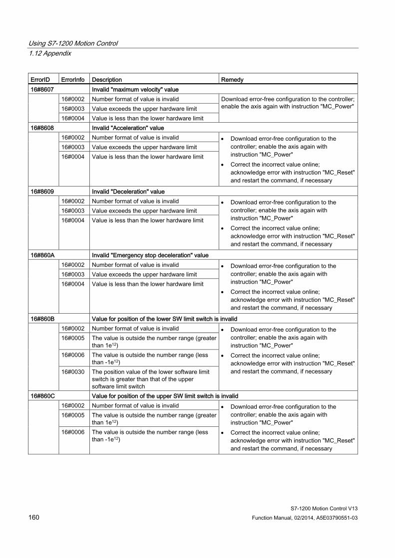
Using S7-1200 Motion Control 1.12 Appendix
S7-1200 Motion Control V13 160 Function Manual, 02/2014, A5E03790551-03
ErrorID ErrorInfo Description Remedy 16#8607 Invalid "maximum velocity" value 16#0002 Number format of value is invalid Download error-free configuration to the controller;
enable the axis again with instruction "MC_Power" 16#0003 Value exceeds the upper hardware limit 16#0004 Value is less than the lower hardware limit
16#8608 Invalid "Acceleration" value 16#0002 Number format of value is invalid • Download error-free configuration to the
controller; enable the axis again with instruction "MC_Power"
• Correct the incorrect value online; acknowledge error with instruction "MC_Reset" and restart the command, if necessary
16#0003 Value exceeds the upper hardware limit 16#0004 Value is less than the lower hardware limit
16#8609 Invalid "Deceleration" value 16#0002 Number format of value is invalid • Download error-free configuration to the
controller; enable the axis again with instruction "MC_Power"
• Correct the incorrect value online; acknowledge error with instruction "MC_Reset" and restart the command, if necessary
16#0003 Value exceeds the upper hardware limit 16#0004 Value is less than the lower hardware limit
16#860A Invalid "Emergency stop deceleration" value 16#0002 Number format of value is invalid • Download error-free configuration to the
controller; enable the axis again with instruction "MC_Power"
• Correct the incorrect value online; acknowledge error with instruction "MC_Reset" and restart the command, if necessary
16#0003 Value exceeds the upper hardware limit 16#0004 Value is less than the lower hardware limit
16#860B Value for position of the lower SW limit switch is invalid 16#0002 Number format of value is invalid • Download error-free configuration to the
controller; enable the axis again with instruction "MC_Power"
• Correct the incorrect value online; acknowledge error with instruction "MC_Reset" and restart the command, if necessary
16#0005 The value is outside the number range (greater than 1e12)
16#0006 The value is outside the number range (less than -1e12)
16#0030 The position value of the lower software limit switch is greater than that of the upper software limit switch
16#860C Value for position of the upper SW limit switch is invalid 16#0002 Number format of value is invalid • Download error-free configuration to the
controller; enable the axis again with instruction "MC_Power"
• Correct the incorrect value online; acknowledge error with instruction "MC_Reset" and restart the command, if necessary
16#0005 The value is outside the number range (greater than 1e12)
16#0006 The value is outside the number range (less than -1e12)
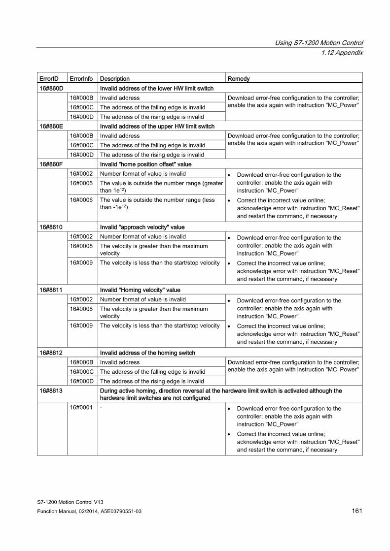
Using S7-1200 Motion Control 1.12 Appendix
S7-1200 Motion Control V13 Function Manual, 02/2014, A5E03790551-03 161
ErrorID ErrorInfo Description Remedy 16#860D Invalid address of the lower HW limit switch 16#000B Invalid address Download error-free configuration to the controller;
enable the axis again with instruction "MC_Power" 16#000C The address of the falling edge is invalid 16#000D The address of the rising edge is invalid
16#860E Invalid address of the upper HW limit switch 16#000B Invalid address Download error-free configuration to the controller;
enable the axis again with instruction "MC_Power" 16#000C The address of the falling edge is invalid 16#000D The address of the rising edge is invalid
16#860F Invalid "home position offset" value 16#0002 Number format of value is invalid • Download error-free configuration to the
controller; enable the axis again with instruction "MC_Power"
• Correct the incorrect value online; acknowledge error with instruction "MC_Reset" and restart the command, if necessary
16#0005 The value is outside the number range (greater than 1e12)
16#0006 The value is outside the number range (less than -1e12)
16#8610 Invalid "approach velocity" value 16#0002 Number format of value is invalid • Download error-free configuration to the
controller; enable the axis again with instruction "MC_Power"
• Correct the incorrect value online; acknowledge error with instruction "MC_Reset" and restart the command, if necessary
16#0008 The velocity is greater than the maximum velocity
16#0009 The velocity is less than the start/stop velocity
16#8611 Invalid "Homing velocity" value 16#0002 Number format of value is invalid • Download error-free configuration to the
controller; enable the axis again with instruction "MC_Power"
• Correct the incorrect value online; acknowledge error with instruction "MC_Reset" and restart the command, if necessary
16#0008 The velocity is greater than the maximum velocity
16#0009 The velocity is less than the start/stop velocity
16#8612 Invalid address of the homing switch 16#000B Invalid address Download error-free configuration to the controller;
enable the axis again with instruction "MC_Power" 16#000C The address of the falling edge is invalid 16#000D The address of the rising edge is invalid
16#8613 During active homing, direction reversal at the hardware limit switch is activated although the hardware limit switches are not configured
16#0001 - • Download error-free configuration to the controller; enable the axis again with instruction "MC_Power"
• Correct the incorrect value online; acknowledge error with instruction "MC_Reset" and restart the command, if necessary
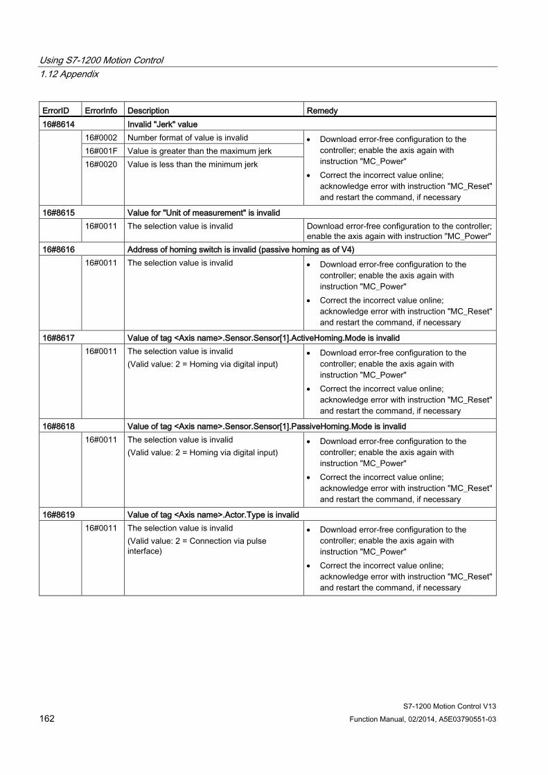
Using S7-1200 Motion Control 1.12 Appendix
S7-1200 Motion Control V13 162 Function Manual, 02/2014, A5E03790551-03
ErrorID ErrorInfo Description Remedy 16#8614 Invalid "Jerk" value 16#0002 Number format of value is invalid • Download error-free configuration to the
controller; enable the axis again with instruction "MC_Power"
• Correct the incorrect value online; acknowledge error with instruction "MC_Reset" and restart the command, if necessary
16#001F Value is greater than the maximum jerk 16#0020 Value is less than the minimum jerk
16#8615 Value for "Unit of measurement" is invalid 16#0011 The selection value is invalid Download error-free configuration to the controller;
enable the axis again with instruction "MC_Power" 16#8616 Address of homing switch is invalid (passive homing as of V4) 16#0011 The selection value is invalid • Download error-free configuration to the
controller; enable the axis again with instruction "MC_Power"
• Correct the incorrect value online; acknowledge error with instruction "MC_Reset" and restart the command, if necessary
16#8617 Value of tag <Axis name>.Sensor.Sensor[1].ActiveHoming.Mode is invalid 16#0011 The selection value is invalid
(Valid value: 2 = Homing via digital input) • Download error-free configuration to the
controller; enable the axis again with instruction "MC_Power"
• Correct the incorrect value online; acknowledge error with instruction "MC_Reset" and restart the command, if necessary
16#8618 Value of tag <Axis name>.Sensor.Sensor[1].PassiveHoming.Mode is invalid 16#0011 The selection value is invalid
(Valid value: 2 = Homing via digital input) • Download error-free configuration to the
controller; enable the axis again with instruction "MC_Power"
• Correct the incorrect value online; acknowledge error with instruction "MC_Reset" and restart the command, if necessary
16#8619 Value of tag <Axis name>.Actor.Type is invalid 16#0011 The selection value is invalid
(Valid value: 2 = Connection via pulse interface)
• Download error-free configuration to the controller; enable the axis again with instruction "MC_Power"
• Correct the incorrect value online; acknowledge error with instruction "MC_Reset" and restart the command, if necessary
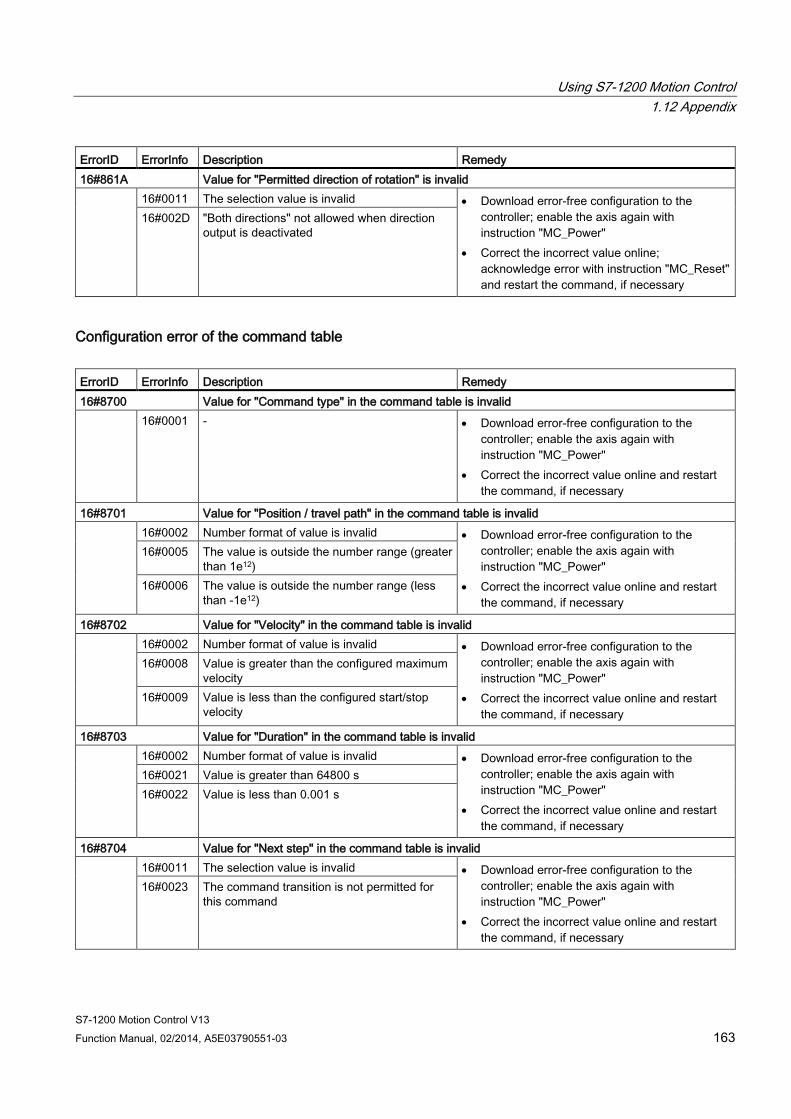
Using S7-1200 Motion Control 1.12 Appendix
S7-1200 Motion Control V13 Function Manual, 02/2014, A5E03790551-03 163
ErrorID ErrorInfo Description Remedy 16#861A Value for "Permitted direction of rotation" is invalid 16#0011 The selection value is invalid • Download error-free configuration to the
controller; enable the axis again with instruction "MC_Power"
• Correct the incorrect value online; acknowledge error with instruction "MC_Reset" and restart the command, if necessary
16#002D "Both directions" not allowed when direction output is deactivated
Configuration error of the command table ErrorID ErrorInfo Description Remedy 16#8700 Value for "Command type" in the command table is invalid 16#0001 - • Download error-free configuration to the
controller; enable the axis again with instruction "MC_Power"
• Correct the incorrect value online and restart the command, if necessary
16#8701 Value for "Position / travel path" in the command table is invalid 16#0002 Number format of value is invalid • Download error-free configuration to the
controller; enable the axis again with instruction "MC_Power"
• Correct the incorrect value online and restart the command, if necessary
16#0005 The value is outside the number range (greater than 1e12)
16#0006 The value is outside the number range (less than -1e12)
16#8702 Value for "Velocity" in the command table is invalid 16#0002 Number format of value is invalid • Download error-free configuration to the
controller; enable the axis again with instruction "MC_Power"
• Correct the incorrect value online and restart the command, if necessary
16#0008 Value is greater than the configured maximum velocity
16#0009 Value is less than the configured start/stop velocity
16#8703 Value for "Duration" in the command table is invalid 16#0002 Number format of value is invalid • Download error-free configuration to the
controller; enable the axis again with instruction "MC_Power"
• Correct the incorrect value online and restart the command, if necessary
16#0021 Value is greater than 64800 s 16#0022 Value is less than 0.001 s
16#8704 Value for "Next step" in the command table is invalid 16#0011 The selection value is invalid • Download error-free configuration to the
controller; enable the axis again with instruction "MC_Power"
• Correct the incorrect value online and restart the command, if necessary
16#0023 The command transition is not permitted for this command
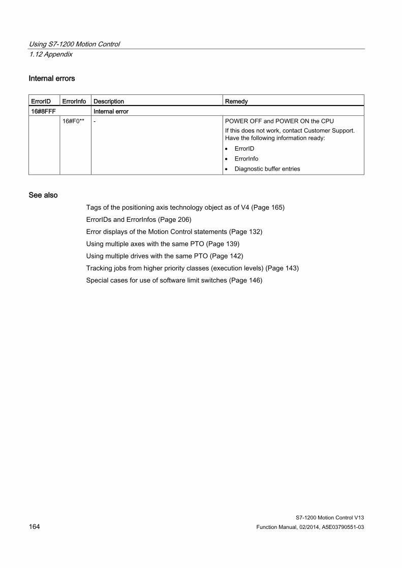
Using S7-1200 Motion Control 1.12 Appendix
S7-1200 Motion Control V13 164 Function Manual, 02/2014, A5E03790551-03
Internal errors ErrorID ErrorInfo Description Remedy 16#8FFF Internal error 16#F0** - POWER OFF and POWER ON the CPU
If this does not work, contact Customer Support. Have the following information ready: • ErrorID • ErrorInfo • Diagnostic buffer entries
See also Tags of the positioning axis technology object as of V4 (Page 165)
ErrorIDs and ErrorInfos (Page 206)
Error displays of the Motion Control statements (Page 132)
Using multiple axes with the same PTO (Page 139)
Using multiple drives with the same PTO (Page 142)
Tracking jobs from higher priority classes (execution levels) (Page 143)
Special cases for use of software limit switches (Page 146)
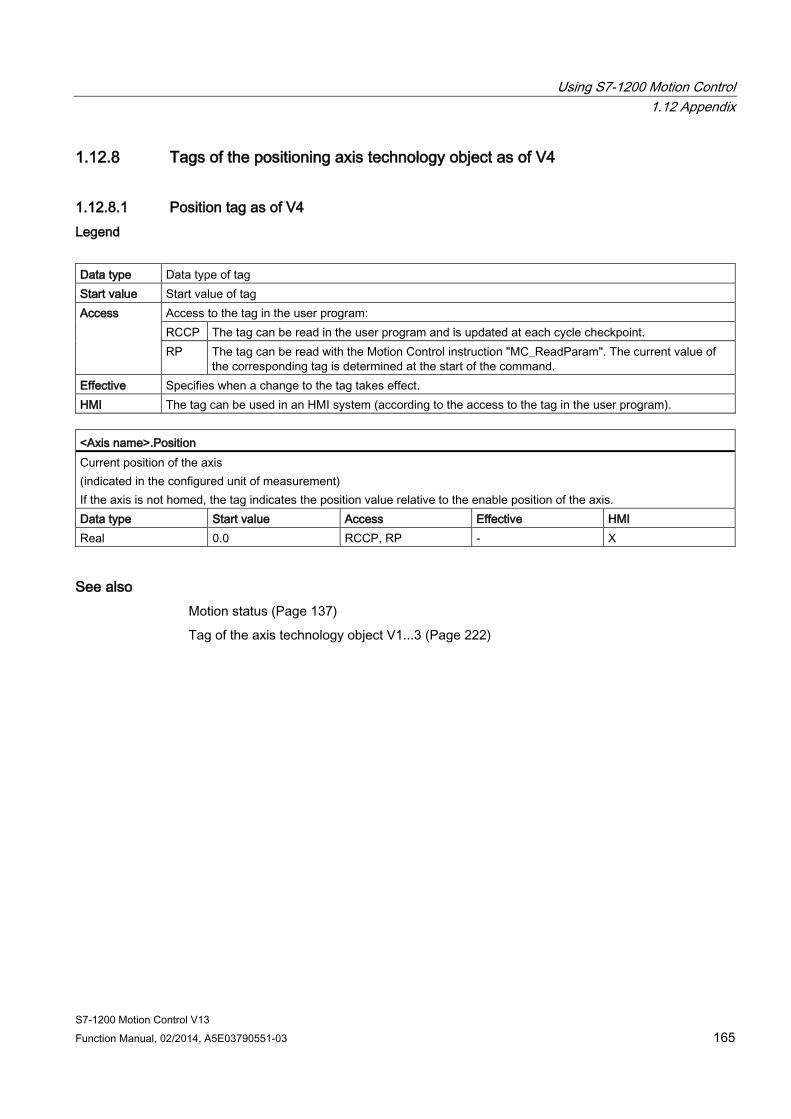
Using S7-1200 Motion Control 1.12 Appendix
S7-1200 Motion Control V13 Function Manual, 02/2014, A5E03790551-03 165
1.12.8 Tags of the positioning axis technology object as of V4
1.12.8.1 Position tag as of V4 Legend
Data type Data type of tag Start value Start value of tag Access Access to the tag in the user program:
RCCP The tag can be read in the user program and is updated at each cycle checkpoint. RP The tag can be read with the Motion Control instruction "MC_ReadParam". The current value of
the corresponding tag is determined at the start of the command. Effective Specifies when a change to the tag takes effect. HMI The tag can be used in an HMI system (according to the access to the tag in the user program).
<Axis name>.Position Current position of the axis (indicated in the configured unit of measurement) If the axis is not homed, the tag indicates the position value relative to the enable position of the axis. Data type Start value Access Effective HMI Real 0.0 RCCP, RP - X
See also Motion status (Page 137)
Tag of the axis technology object V1...3 (Page 222)
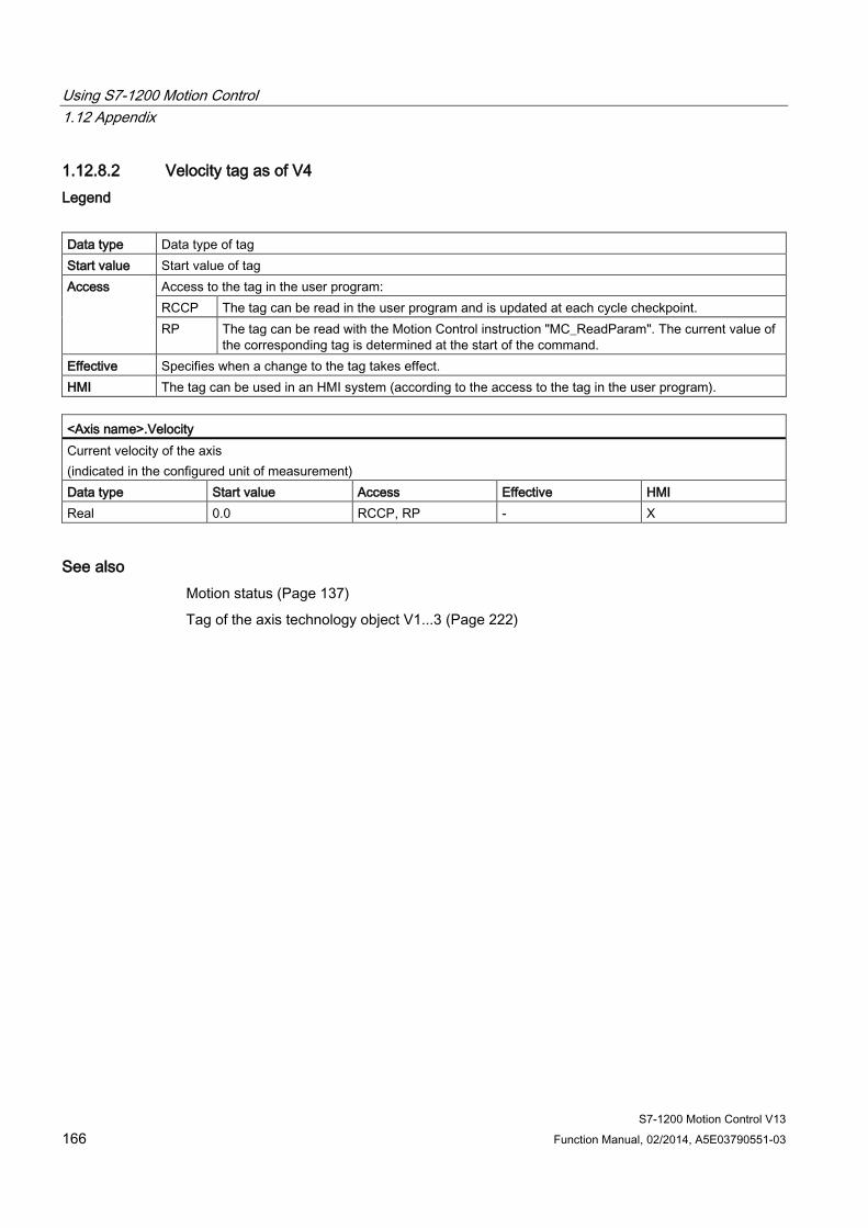
Using S7-1200 Motion Control 1.12 Appendix
S7-1200 Motion Control V13 166 Function Manual, 02/2014, A5E03790551-03
1.12.8.2 Velocity tag as of V4 Legend
Data type Data type of tag Start value Start value of tag Access Access to the tag in the user program:
RCCP The tag can be read in the user program and is updated at each cycle checkpoint. RP The tag can be read with the Motion Control instruction "MC_ReadParam". The current value of
the corresponding tag is determined at the start of the command. Effective Specifies when a change to the tag takes effect. HMI The tag can be used in an HMI system (according to the access to the tag in the user program).
<Axis name>.Velocity Current velocity of the axis (indicated in the configured unit of measurement) Data type Start value Access Effective HMI Real 0.0 RCCP, RP - X
See also Motion status (Page 137)
Tag of the axis technology object V1...3 (Page 222)

Using S7-1200 Motion Control 1.12 Appendix
S7-1200 Motion Control V13 Function Manual, 02/2014, A5E03790551-03 167
1.12.8.3 Actor tags as of V4 Legend
Data type Data type of tag Start value Start value of tag Access Access to the tag in the user program:
R The tag can be read in the user program. WP If the axis is disabled (MC_Power.Status = FALSE), the tag can be written with the Motion Control
instruction "MC_WriteParam". - The tag cannot be used in the user program.
Effective Specifies when a change to the tag takes effect: 2 When axis is enabled
HMI The tag can be used in an HMI system (according to the access to the tag in the user program).
<Axis name>.Actor.Type Drive connection The drive is connected via a pulse interface. Data type Start value Access Effective HMI DInt 2 R - X
<Axis name>.Actor.InverseDirection Invert direction FALSE = The direction is not inverted. TRUE = The direction is inverted. Data type Start value Access Effective HMI Bool FALSE R - X
WP 2 -
<Axis name>.Actor.DirectionMode Permitted direction of rotation 0 = Both directions 1 = Positive direction 2 = Negative direction Data type Start value Access Effective HMI Int 0 R - X
WP 2 -
<Axis name>.Actor.Interface.EnableDriveOutput Enable output (internal parameter) Data type Start value Access Effective HMI VREF - - - -
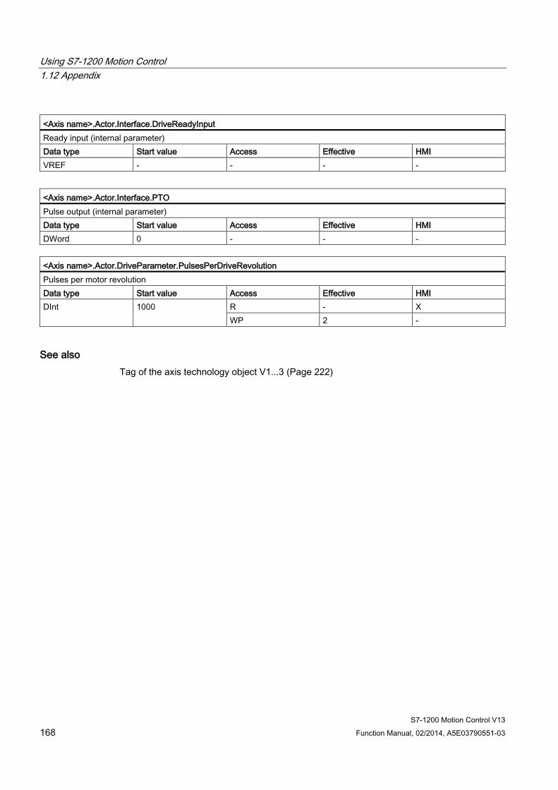
Using S7-1200 Motion Control 1.12 Appendix
S7-1200 Motion Control V13 168 Function Manual, 02/2014, A5E03790551-03
<Axis name>.Actor.Interface.DriveReadyInput Ready input (internal parameter) Data type Start value Access Effective HMI VREF - - - -
<Axis name>.Actor.Interface.PTO Pulse output (internal parameter) Data type Start value Access Effective HMI DWord 0 - - -
<Axis name>.Actor.DriveParameter.PulsesPerDriveRevolution Pulses per motor revolution Data type Start value Access Effective HMI DInt 1000 R - X
WP 2 -
See also Tag of the axis technology object V1...3 (Page 222)

Using S7-1200 Motion Control 1.12 Appendix
S7-1200 Motion Control V13 Function Manual, 02/2014, A5E03790551-03 169
1.12.8.4 Sensor[1] tags as of V4
ActiveHoming tags as of V4 Legend
Data type Data type of tag Start value Start value of tag
The start value can be overwritten by the axis configuration. Access Access to the tag in the user program:
RW The tag can be read and written in the user program. The tag can be written with Motion Control instruction "MC_WriteParam".
R The tag can be read in the user program. WP If the axis is disabled (MC_Power.Status = FALSE), the tag can be written with the Motion Control
instruction "MC_WriteParam". - The tag cannot be used in the user program.
Effective Specifies when a change to the tag takes effect: 1 When axis is activated (<Axis name>.StatusBits.Activated tag changes from FALSE → TRUE),
disabled, or enabled 2 When axis is enabled 8 When an active homing command is started
HMI The tag can be used in an HMI system (according to the access to the tag in the user program).
<Axis name>.Sensor[1].ActiveHoming.Mode Active homing mode 2 = Homing via digital input Data type Start value Access Effective HMI DInt 2 R - X
WP 2 -
<Axis name>.Sensor[1].ActiveHoming.SideInput End of the homing switch to which the axis is homed during active homing FALSE = Lower end TRUE = Upper end Data type Start value Access Effective HMI Bool FALSE RW 1, 8 X
<Axis name>.Sensor[1].ActiveHoming.DigitalInputAddress Symbolic input address of the homing switch (internal parameter) Data type Start value Access Effective HMI VREF - - - -
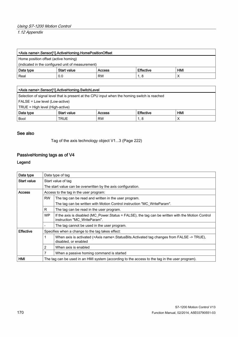
Using S7-1200 Motion Control 1.12 Appendix
S7-1200 Motion Control V13 170 Function Manual, 02/2014, A5E03790551-03
<Axis name>.Sensor[1].ActiveHoming.HomePositionOffset Home position offset (active homing) (indicated in the configured unit of measurement) Data type Start value Access Effective HMI Real 0.0 RW 1, 8 X
<Axis name>.Sensor[1].ActiveHoming.SwitchLevel Selection of signal level that is present at the CPU input when the homing switch is reached FALSE = Low level (Low-active) TRUE = High level (High-active) Data type Start value Access Effective HMI Bool TRUE RW 1, 8 X
See also Tag of the axis technology object V1...3 (Page 222)
PassiveHoming tags as of V4 Legend
Data type Data type of tag Start value Start value of tag
The start value can be overwritten by the axis configuration. Access Access to the tag in the user program:
RW The tag can be read and written in the user program. The tag can be written with Motion Control instruction "MC_WriteParam".
R The tag can be read in the user program. WP If the axis is disabled (MC_Power.Status = FALSE), the tag can be written with the Motion Control
instruction "MC_WriteParam". - The tag cannot be used in the user program.
Effective Specifies when a change to the tag takes effect: 1 When axis is activated (<Axis name>.StatusBits.Activated tag changes from FALSE -> TRUE),
disabled, or enabled 2 When axis is enabled 7 When a passive homing command is started
HMI The tag can be used in an HMI system (according to the access to the tag in the user program).

Using S7-1200 Motion Control 1.12 Appendix
S7-1200 Motion Control V13 Function Manual, 02/2014, A5E03790551-03 171
<Axis name>.Sensor[1].PassiveHoming.Mode Passive homing mode 2 = Homing via digital input Data type Start value Access Effective HMI DInt 2 R - X
WP 2 -
<Axis name>.Sensor[1].PassiveHoming.SideInput End of the homing switch to which the axis is homed during passive homing FALSE = Lower end TRUE = Upper end Data type Start value Access Effective HMI Bool FALSE RW 1, 7 X
<Axis name>.Sensor[1].PassiveHoming.DigitalInputAddress Symbolic input address of the homing switch (internal parameter) Data type Start value Access Effective HMI VREF - - - -
<Axis name>.Sensor[1].PassiveHoming.SwitchLevel Selection of level that is present at the CPU input when the homing switch is reached FALSE = Low level (Low-active) TRUE = High level (High-active) Data type Start value Access Effective HMI Bool TRUE RW 1, 7 X
See also Tag of the axis technology object V1...3 (Page 222)
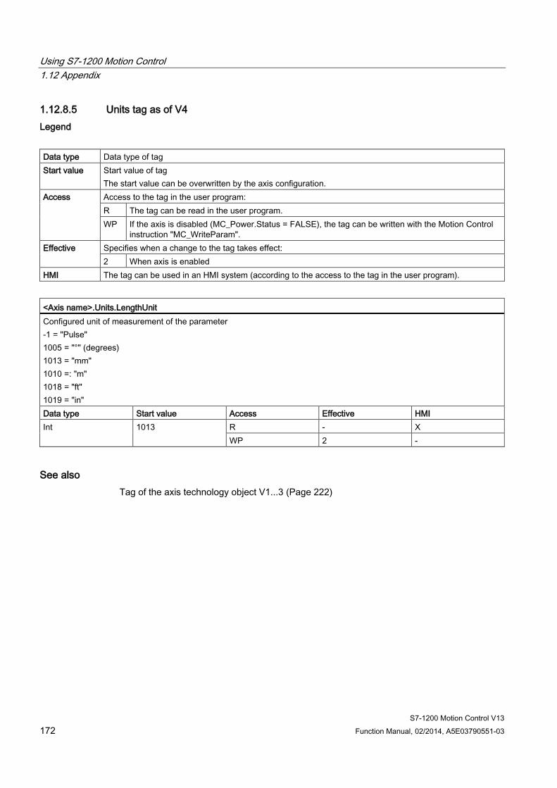
Using S7-1200 Motion Control 1.12 Appendix
S7-1200 Motion Control V13 172 Function Manual, 02/2014, A5E03790551-03
1.12.8.5 Units tag as of V4 Legend
Data type Data type of tag Start value Start value of tag
The start value can be overwritten by the axis configuration. Access Access to the tag in the user program:
R The tag can be read in the user program. WP If the axis is disabled (MC_Power.Status = FALSE), the tag can be written with the Motion Control
instruction "MC_WriteParam". Effective Specifies when a change to the tag takes effect:
2 When axis is enabled HMI The tag can be used in an HMI system (according to the access to the tag in the user program).
<Axis name>.Units.LengthUnit Configured unit of measurement of the parameter -1 = "Pulse" 1005 = "°" (degrees) 1013 = "mm" 1010 =: "m" 1018 = "ft" 1019 = "in" Data type Start value Access Effective HMI Int 1013 R - X
WP 2 -
See also Tag of the axis technology object V1...3 (Page 222)
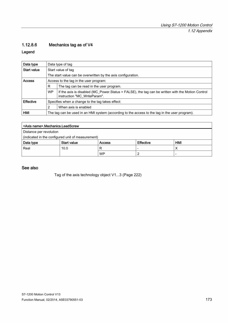
Using S7-1200 Motion Control 1.12 Appendix
S7-1200 Motion Control V13 Function Manual, 02/2014, A5E03790551-03 173
1.12.8.6 Mechanics tag as of V4 Legend
Data type Data type of tag Start value Start value of tag
The start value can be overwritten by the axis configuration. Access Access to the tag in the user program:
R The tag can be read in the user program. WP If the axis is disabled (MC_Power.Status = FALSE), the tag can be written with the Motion Control
instruction "MC_WriteParam". Effective Specifies when a change to the tag takes effect:
2 When axis is enabled HMI The tag can be used in an HMI system (according to the access to the tag in the user program).
<Axis name>.Mechanics.LeadScrew Distance per revolution (indicated in the configured unit of measurement) Data type Start value Access Effective HMI Real 10.0 R - X
WP 2 -
See also Tag of the axis technology object V1...3 (Page 222)
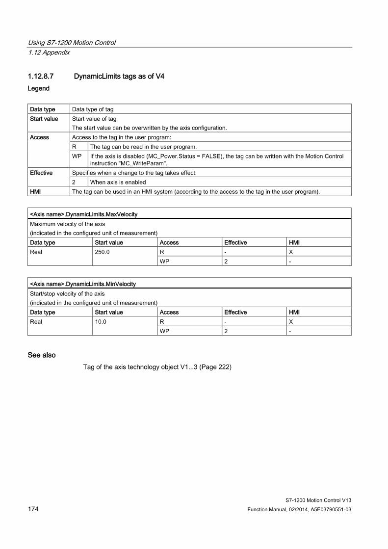
Using S7-1200 Motion Control 1.12 Appendix
S7-1200 Motion Control V13 174 Function Manual, 02/2014, A5E03790551-03
1.12.8.7 DynamicLimits tags as of V4 Legend
Data type Data type of tag Start value Start value of tag
The start value can be overwritten by the axis configuration. Access Access to the tag in the user program:
R The tag can be read in the user program. WP If the axis is disabled (MC_Power.Status = FALSE), the tag can be written with the Motion Control
instruction "MC_WriteParam". Effective Specifies when a change to the tag takes effect:
2 When axis is enabled HMI The tag can be used in an HMI system (according to the access to the tag in the user program).
<Axis name>.DynamicLimits.MaxVelocity Maximum velocity of the axis (indicated in the configured unit of measurement) Data type Start value Access Effective HMI Real 250.0 R - X
WP 2 -
<Axis name>.DynamicLimits.MinVelocity Start/stop velocity of the axis (indicated in the configured unit of measurement) Data type Start value Access Effective HMI Real 10.0 R - X
WP 2 -
See also Tag of the axis technology object V1...3 (Page 222)
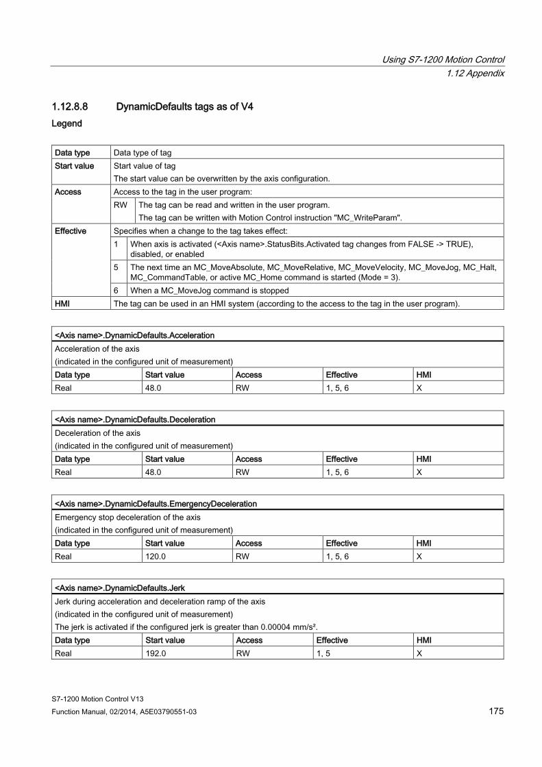
Using S7-1200 Motion Control 1.12 Appendix
S7-1200 Motion Control V13 Function Manual, 02/2014, A5E03790551-03 175
1.12.8.8 DynamicDefaults tags as of V4 Legend
Data type Data type of tag Start value Start value of tag
The start value can be overwritten by the axis configuration. Access Access to the tag in the user program:
RW The tag can be read and written in the user program. The tag can be written with Motion Control instruction "MC_WriteParam".
Effective Specifies when a change to the tag takes effect: 1 When axis is activated (<Axis name>.StatusBits.Activated tag changes from FALSE -> TRUE),
disabled, or enabled 5 The next time an MC_MoveAbsolute, MC_MoveRelative, MC_MoveVelocity, MC_MoveJog, MC_Halt,
MC_CommandTable, or active MC_Home command is started (Mode = 3). 6 When a MC_MoveJog command is stopped
HMI The tag can be used in an HMI system (according to the access to the tag in the user program).
<Axis name>.DynamicDefaults.Acceleration Acceleration of the axis (indicated in the configured unit of measurement) Data type Start value Access Effective HMI Real 48.0 RW 1, 5, 6 X
<Axis name>.DynamicDefaults.Deceleration Deceleration of the axis (indicated in the configured unit of measurement) Data type Start value Access Effective HMI Real 48.0 RW 1, 5, 6 X
<Axis name>.DynamicDefaults.EmergencyDeceleration Emergency stop deceleration of the axis (indicated in the configured unit of measurement) Data type Start value Access Effective HMI Real 120.0 RW 1, 5, 6 X
<Axis name>.DynamicDefaults.Jerk Jerk during acceleration and deceleration ramp of the axis (indicated in the configured unit of measurement) The jerk is activated if the configured jerk is greater than 0.00004 mm/s². Data type Start value Access Effective HMI Real 192.0 RW 1, 5 X
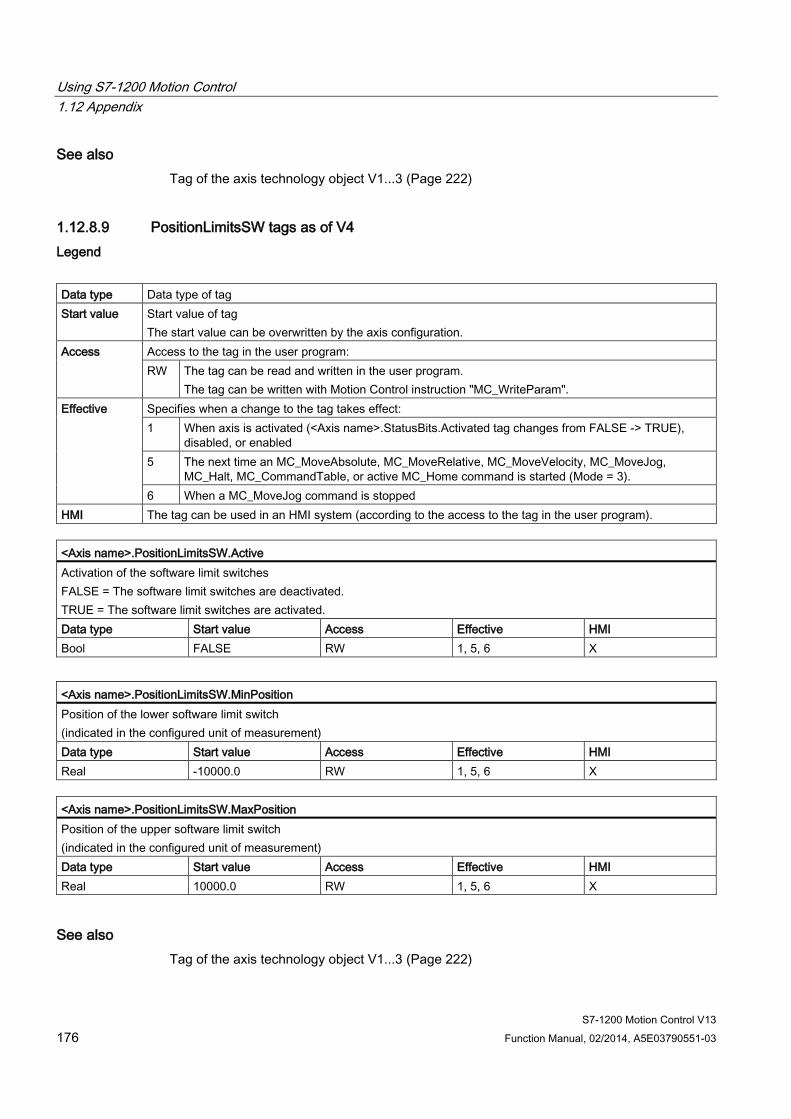
Using S7-1200 Motion Control 1.12 Appendix
S7-1200 Motion Control V13 176 Function Manual, 02/2014, A5E03790551-03
See also Tag of the axis technology object V1...3 (Page 222)
1.12.8.9 PositionLimitsSW tags as of V4 Legend
Data type Data type of tag Start value Start value of tag
The start value can be overwritten by the axis configuration. Access Access to the tag in the user program:
RW The tag can be read and written in the user program. The tag can be written with Motion Control instruction "MC_WriteParam".
Effective Specifies when a change to the tag takes effect: 1 When axis is activated (<Axis name>.StatusBits.Activated tag changes from FALSE -> TRUE),
disabled, or enabled 5 The next time an MC_MoveAbsolute, MC_MoveRelative, MC_MoveVelocity, MC_MoveJog,
MC_Halt, MC_CommandTable, or active MC_Home command is started (Mode = 3). 6 When a MC_MoveJog command is stopped
HMI The tag can be used in an HMI system (according to the access to the tag in the user program).
<Axis name>.PositionLimitsSW.Active Activation of the software limit switches FALSE = The software limit switches are deactivated. TRUE = The software limit switches are activated. Data type Start value Access Effective HMI Bool FALSE RW 1, 5, 6 X
<Axis name>.PositionLimitsSW.MinPosition Position of the lower software limit switch (indicated in the configured unit of measurement) Data type Start value Access Effective HMI Real -10000.0 RW 1, 5, 6 X
<Axis name>.PositionLimitsSW.MaxPosition Position of the upper software limit switch (indicated in the configured unit of measurement) Data type Start value Access Effective HMI Real 10000.0 RW 1, 5, 6 X
See also Tag of the axis technology object V1...3 (Page 222)
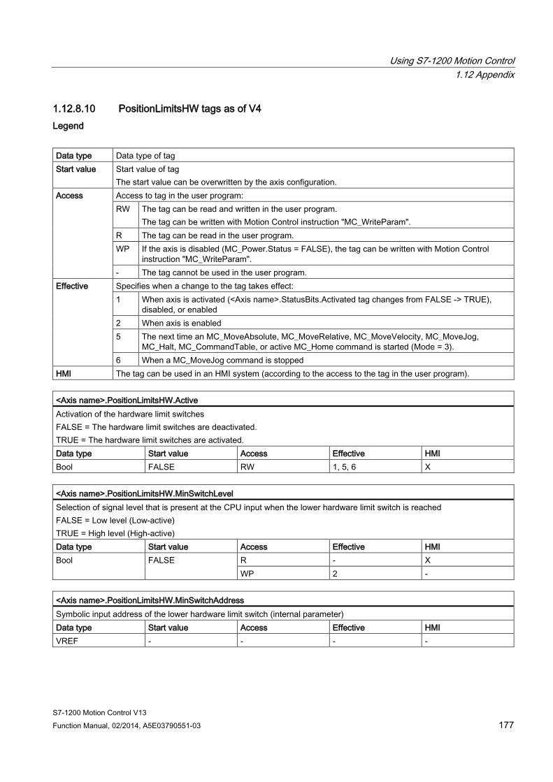
Using S7-1200 Motion Control 1.12 Appendix
S7-1200 Motion Control V13 Function Manual, 02/2014, A5E03790551-03 177
1.12.8.10 PositionLimitsHW tags as of V4 Legend
Data type Data type of tag Start value Start value of tag
The start value can be overwritten by the axis configuration. Access Access to tag in the user program:
RW The tag can be read and written in the user program. The tag can be written with Motion Control instruction "MC_WriteParam".
R The tag can be read in the user program. WP If the axis is disabled (MC_Power.Status = FALSE), the tag can be written with Motion Control
instruction "MC_WriteParam". - The tag cannot be used in the user program.
Effective Specifies when a change to the tag takes effect: 1 When axis is activated (<Axis name>.StatusBits.Activated tag changes from FALSE -> TRUE),
disabled, or enabled 2 When axis is enabled 5 The next time an MC_MoveAbsolute, MC_MoveRelative, MC_MoveVelocity, MC_MoveJog,
MC_Halt, MC_CommandTable, or active MC_Home command is started (Mode = 3). 6 When a MC_MoveJog command is stopped
HMI The tag can be used in an HMI system (according to the access to the tag in the user program).
<Axis name>.PositionLimitsHW.Active Activation of the hardware limit switches FALSE = The hardware limit switches are deactivated. TRUE = The hardware limit switches are activated. Data type Start value Access Effective HMI Bool FALSE RW 1, 5, 6 X
<Axis name>.PositionLimitsHW.MinSwitchLevel Selection of signal level that is present at the CPU input when the lower hardware limit switch is reached FALSE = Low level (Low-active) TRUE = High level (High-active) Data type Start value Access Effective HMI Bool FALSE R - X
WP 2 -
<Axis name>.PositionLimitsHW.MinSwitchAddress Symbolic input address of the lower hardware limit switch (internal parameter) Data type Start value Access Effective HMI VREF - - - -
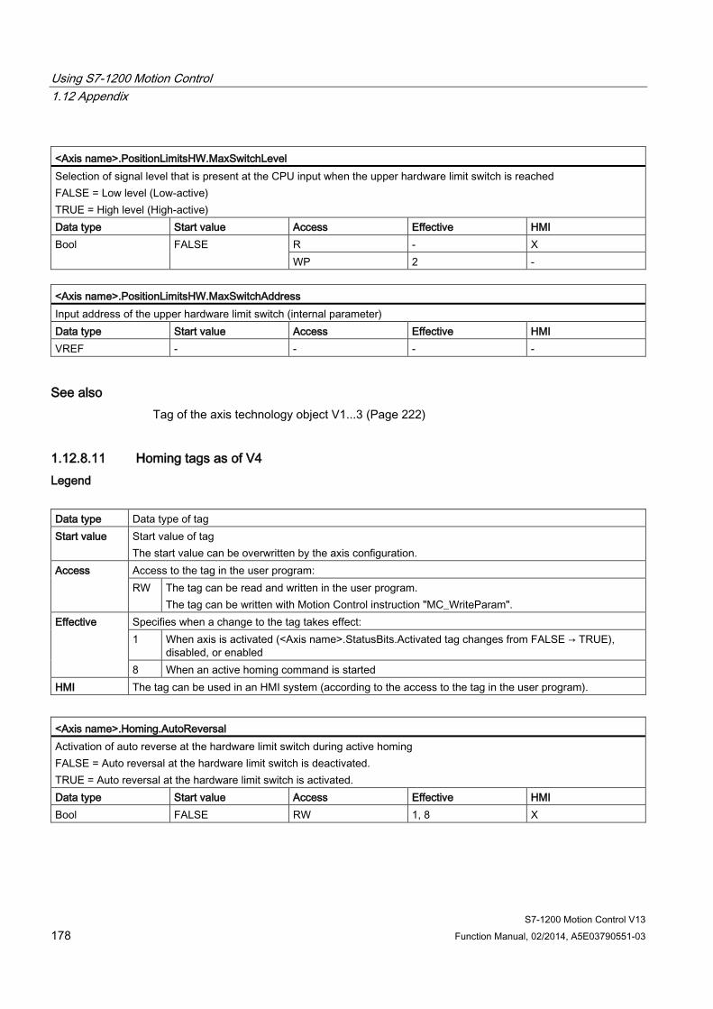
Using S7-1200 Motion Control 1.12 Appendix
S7-1200 Motion Control V13 178 Function Manual, 02/2014, A5E03790551-03
<Axis name>.PositionLimitsHW.MaxSwitchLevel Selection of signal level that is present at the CPU input when the upper hardware limit switch is reached FALSE = Low level (Low-active) TRUE = High level (High-active) Data type Start value Access Effective HMI Bool FALSE R - X
WP 2 -
<Axis name>.PositionLimitsHW.MaxSwitchAddress Input address of the upper hardware limit switch (internal parameter) Data type Start value Access Effective HMI VREF - - - -
See also Tag of the axis technology object V1...3 (Page 222)
1.12.8.11 Homing tags as of V4 Legend
Data type Data type of tag Start value Start value of tag
The start value can be overwritten by the axis configuration. Access Access to the tag in the user program:
RW The tag can be read and written in the user program. The tag can be written with Motion Control instruction "MC_WriteParam".
Effective Specifies when a change to the tag takes effect: 1 When axis is activated (<Axis name>.StatusBits.Activated tag changes from FALSE → TRUE),
disabled, or enabled 8 When an active homing command is started
HMI The tag can be used in an HMI system (according to the access to the tag in the user program).
<Axis name>.Homing.AutoReversal Activation of auto reverse at the hardware limit switch during active homing FALSE = Auto reversal at the hardware limit switch is deactivated. TRUE = Auto reversal at the hardware limit switch is activated. Data type Start value Access Effective HMI Bool FALSE RW 1, 8 X
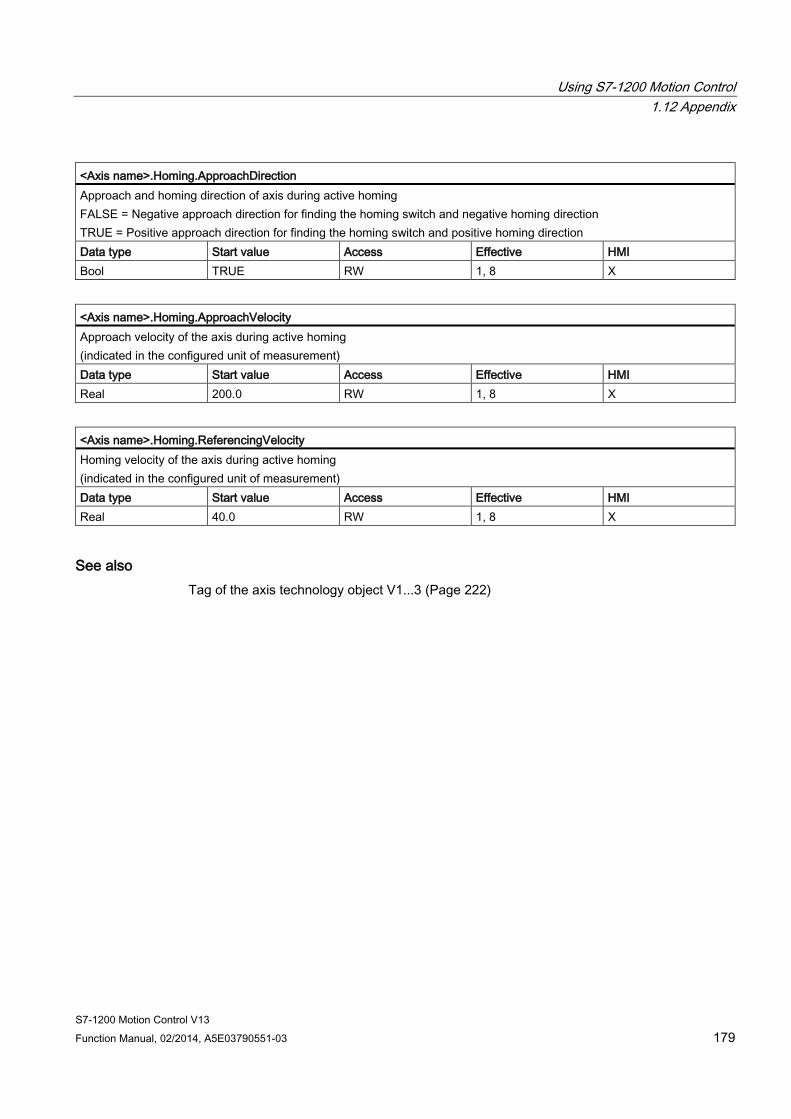
Using S7-1200 Motion Control 1.12 Appendix
S7-1200 Motion Control V13 Function Manual, 02/2014, A5E03790551-03 179
<Axis name>.Homing.ApproachDirection Approach and homing direction of axis during active homing FALSE = Negative approach direction for finding the homing switch and negative homing direction TRUE = Positive approach direction for finding the homing switch and positive homing direction Data type Start value Access Effective HMI Bool TRUE RW 1, 8 X
<Axis name>.Homing.ApproachVelocity Approach velocity of the axis during active homing (indicated in the configured unit of measurement) Data type Start value Access Effective HMI Real 200.0 RW 1, 8 X
<Axis name>.Homing.ReferencingVelocity Homing velocity of the axis during active homing (indicated in the configured unit of measurement) Data type Start value Access Effective HMI Real 40.0 RW 1, 8 X
See also Tag of the axis technology object V1...3 (Page 222)
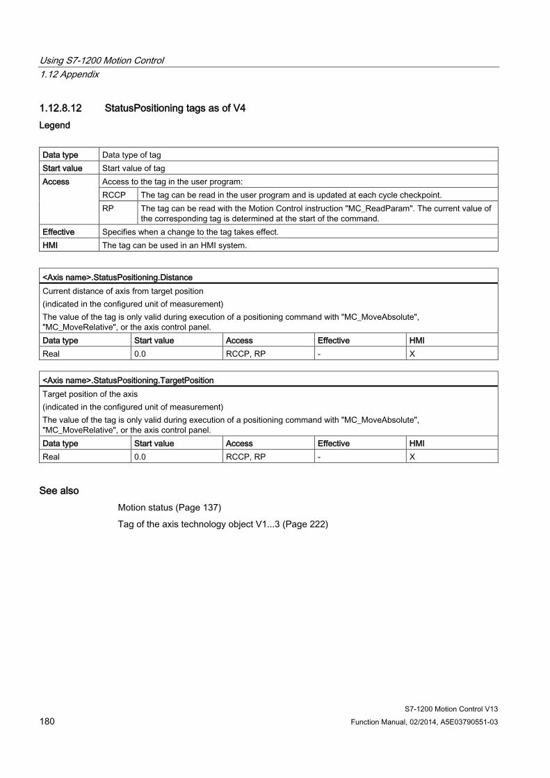
Using S7-1200 Motion Control 1.12 Appendix
S7-1200 Motion Control V13 180 Function Manual, 02/2014, A5E03790551-03
1.12.8.12 StatusPositioning tags as of V4 Legend
Data type Data type of tag Start value Start value of tag Access Access to the tag in the user program:
RCCP The tag can be read in the user program and is updated at each cycle checkpoint. RP The tag can be read with the Motion Control instruction "MC_ReadParam". The current value of
the corresponding tag is determined at the start of the command. Effective Specifies when a change to the tag takes effect. HMI The tag can be used in an HMI system.
<Axis name>.StatusPositioning.Distance Current distance of axis from target position (indicated in the configured unit of measurement) The value of the tag is only valid during execution of a positioning command with "MC_MoveAbsolute", "MC_MoveRelative", or the axis control panel. Data type Start value Access Effective HMI Real 0.0 RCCP, RP - X
<Axis name>.StatusPositioning.TargetPosition Target position of the axis (indicated in the configured unit of measurement) The value of the tag is only valid during execution of a positioning command with "MC_MoveAbsolute", "MC_MoveRelative", or the axis control panel. Data type Start value Access Effective HMI Real 0.0 RCCP, RP - X
See also Motion status (Page 137)
Tag of the axis technology object V1...3 (Page 222)
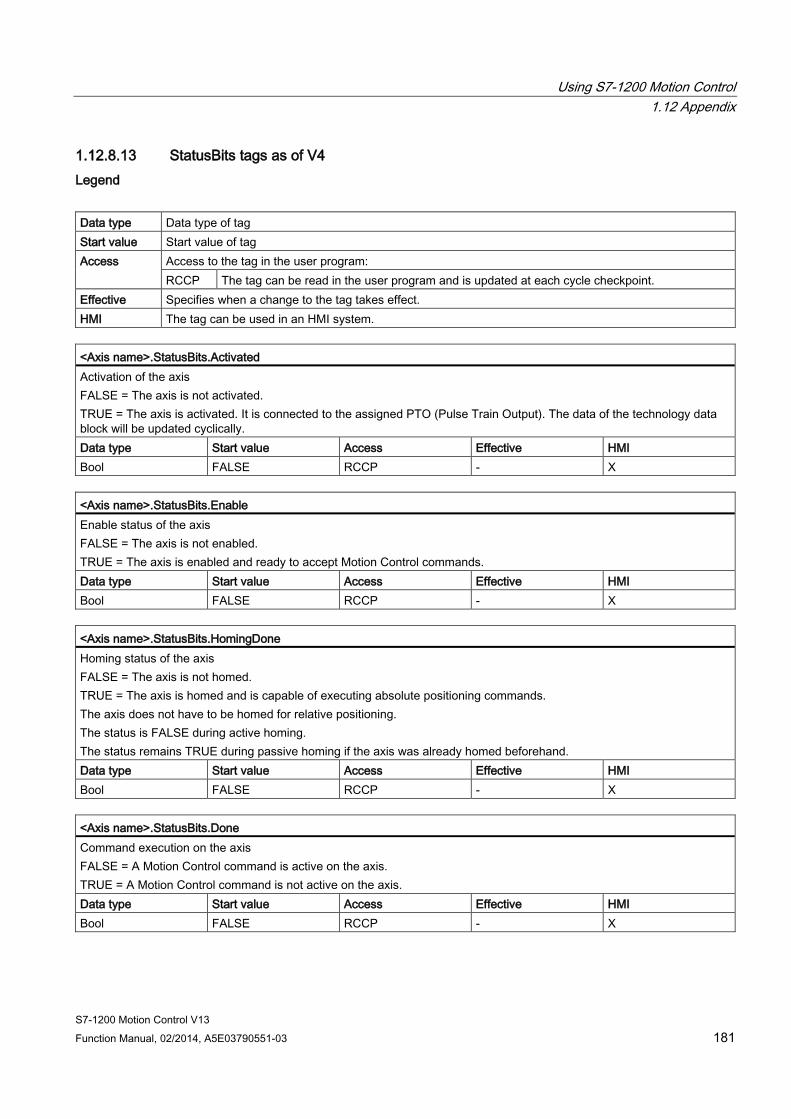
Using S7-1200 Motion Control 1.12 Appendix
S7-1200 Motion Control V13 Function Manual, 02/2014, A5E03790551-03 181
1.12.8.13 StatusBits tags as of V4 Legend
Data type Data type of tag Start value Start value of tag Access Access to the tag in the user program:
RCCP The tag can be read in the user program and is updated at each cycle checkpoint. Effective Specifies when a change to the tag takes effect. HMI The tag can be used in an HMI system.
<Axis name>.StatusBits.Activated Activation of the axis FALSE = The axis is not activated. TRUE = The axis is activated. It is connected to the assigned PTO (Pulse Train Output). The data of the technology data block will be updated cyclically. Data type Start value Access Effective HMI Bool FALSE RCCP - X
<Axis name>.StatusBits.Enable Enable status of the axis FALSE = The axis is not enabled. TRUE = The axis is enabled and ready to accept Motion Control commands. Data type Start value Access Effective HMI Bool FALSE RCCP - X
<Axis name>.StatusBits.HomingDone Homing status of the axis FALSE = The axis is not homed. TRUE = The axis is homed and is capable of executing absolute positioning commands. The axis does not have to be homed for relative positioning. The status is FALSE during active homing. The status remains TRUE during passive homing if the axis was already homed beforehand. Data type Start value Access Effective HMI Bool FALSE RCCP - X
<Axis name>.StatusBits.Done Command execution on the axis FALSE = A Motion Control command is active on the axis. TRUE = A Motion Control command is not active on the axis. Data type Start value Access Effective HMI Bool FALSE RCCP - X
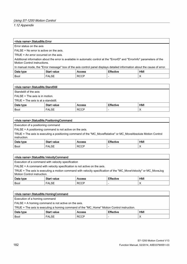
Using S7-1200 Motion Control 1.12 Appendix
S7-1200 Motion Control V13 182 Function Manual, 02/2014, A5E03790551-03
<Axis name>.StatusBits.Error Error status on the axis FALSE = No error is active on the axis. TRUE = An error occurred on the axis. Additional information about the error is available in automatic control at the "ErrorID" and "ErrorInfo" parameters of the Motion Control instructions. In manual mode, the "Error message" box of the axis control panel displays detailed information about the cause of error. Data type Start value Access Effective HMI Bool FALSE RCCP - X
<Axis name>.StatusBits.StandStill Standstill of the axis FALSE = The axis is in motion. TRUE = The axis is at a standstill. Data type Start value Access Effective HMI Bool FALSE RCCP - X
<Axis name>.StatusBits.PositioningCommand Execution of a positioning command FALSE = A positioning command is not active on the axis. TRUE = The axis is executing a positioning command of the "MC_MoveRelative" or MC_MoveAbsolute Motion Control instruction. Data type Start value Access Effective HMI Bool FALSE RCCP - X
<Axis name>.StatusBits.VelocityCommand Execution of a command with velocity specification FALSE = A command with velocity specification is not active on the axis. TRUE = The axis is executing a motion command with velocity specification of the "MC_MoveVelocity" or MC_MoveJog Motion Control instruction. Data type Start value Access Effective HMI Bool FALSE RCCP - X
<Axis name>.StatusBits.HomingCommand Execution of a homing command FALSE = A homing command is not active on the axis. TRUE = The axis is executing a homing command of the "MC_Home" Motion Control instruction. Data type Start value Access Effective HMI Bool FALSE RCCP - X
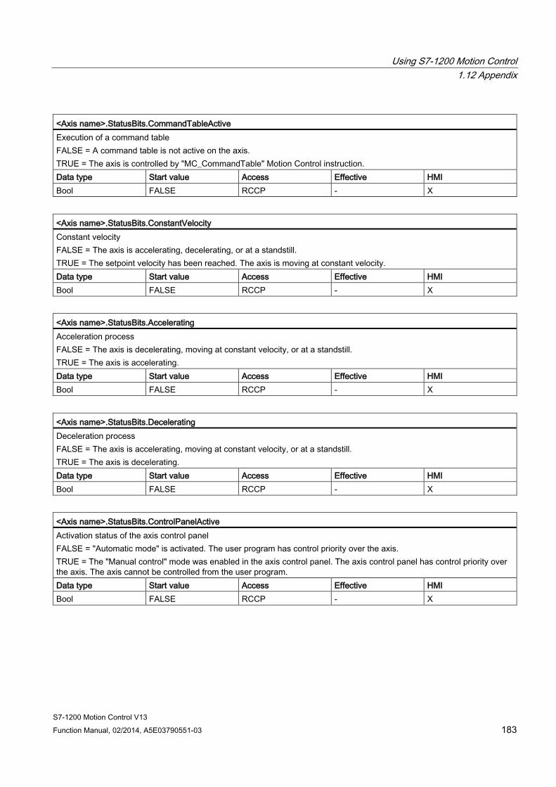
Using S7-1200 Motion Control 1.12 Appendix
S7-1200 Motion Control V13 Function Manual, 02/2014, A5E03790551-03 183
<Axis name>.StatusBits.CommandTableActive Execution of a command table FALSE = A command table is not active on the axis. TRUE = The axis is controlled by "MC_CommandTable" Motion Control instruction. Data type Start value Access Effective HMI Bool FALSE RCCP - X
<Axis name>.StatusBits.ConstantVelocity Constant velocity FALSE = The axis is accelerating, decelerating, or at a standstill. TRUE = The setpoint velocity has been reached. The axis is moving at constant velocity. Data type Start value Access Effective HMI Bool FALSE RCCP - X
<Axis name>.StatusBits.Accelerating Acceleration process FALSE = The axis is decelerating, moving at constant velocity, or at a standstill. TRUE = The axis is accelerating. Data type Start value Access Effective HMI Bool FALSE RCCP - X
<Axis name>.StatusBits.Decelerating Deceleration process FALSE = The axis is accelerating, moving at constant velocity, or at a standstill. TRUE = The axis is decelerating. Data type Start value Access Effective HMI Bool FALSE RCCP - X
<Axis name>.StatusBits.ControlPanelActive Activation status of the axis control panel FALSE = "Automatic mode" is activated. The user program has control priority over the axis. TRUE = The "Manual control" mode was enabled in the axis control panel. The axis control panel has control priority over the axis. The axis cannot be controlled from the user program. Data type Start value Access Effective HMI Bool FALSE RCCP - X
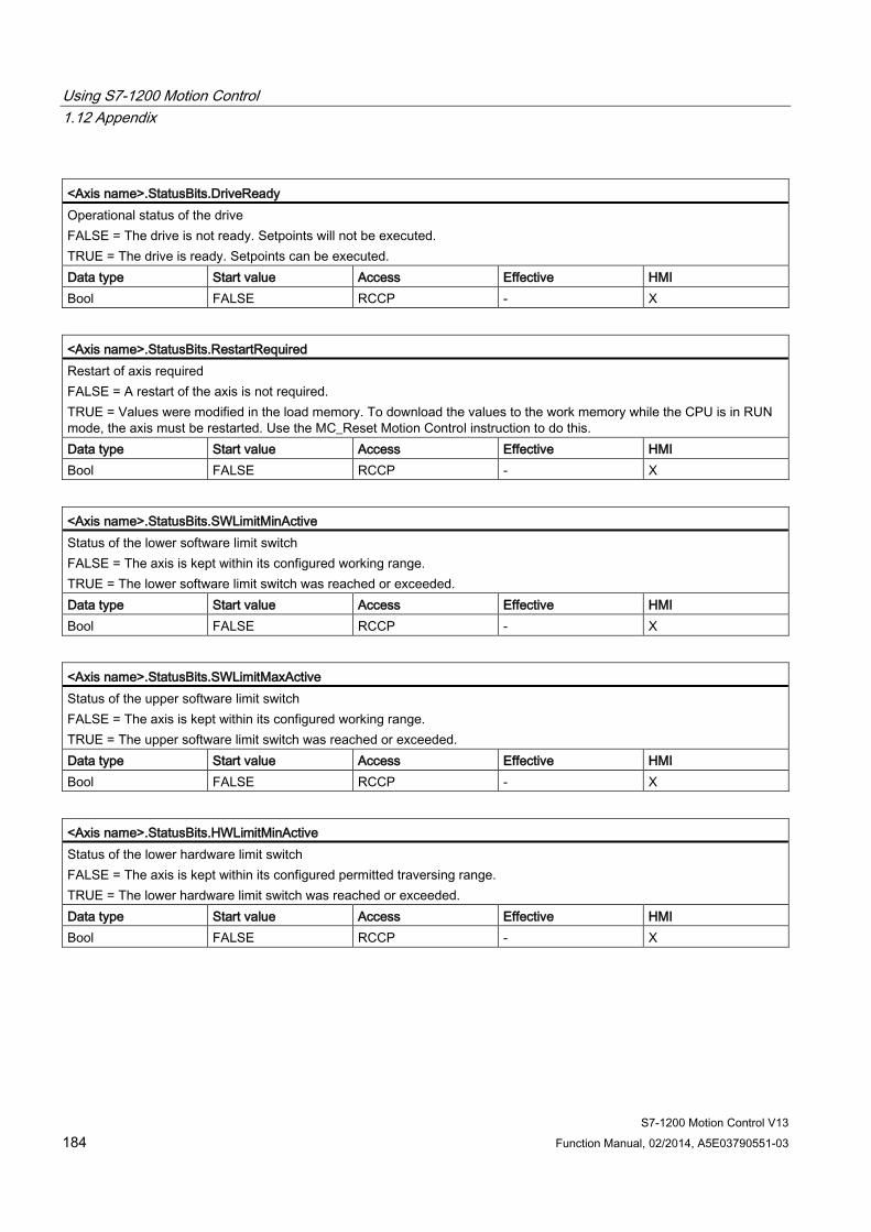
Using S7-1200 Motion Control 1.12 Appendix
S7-1200 Motion Control V13 184 Function Manual, 02/2014, A5E03790551-03
<Axis name>.StatusBits.DriveReady Operational status of the drive FALSE = The drive is not ready. Setpoints will not be executed. TRUE = The drive is ready. Setpoints can be executed. Data type Start value Access Effective HMI Bool FALSE RCCP - X
<Axis name>.StatusBits.RestartRequired Restart of axis required FALSE = A restart of the axis is not required. TRUE = Values were modified in the load memory. To download the values to the work memory while the CPU is in RUN mode, the axis must be restarted. Use the MC_Reset Motion Control instruction to do this. Data type Start value Access Effective HMI Bool FALSE RCCP - X
<Axis name>.StatusBits.SWLimitMinActive Status of the lower software limit switch FALSE = The axis is kept within its configured working range. TRUE = The lower software limit switch was reached or exceeded. Data type Start value Access Effective HMI Bool FALSE RCCP - X
<Axis name>.StatusBits.SWLimitMaxActive Status of the upper software limit switch FALSE = The axis is kept within its configured working range. TRUE = The upper software limit switch was reached or exceeded. Data type Start value Access Effective HMI Bool FALSE RCCP - X
<Axis name>.StatusBits.HWLimitMinActive Status of the lower hardware limit switch FALSE = The axis is kept within its configured permitted traversing range. TRUE = The lower hardware limit switch was reached or exceeded. Data type Start value Access Effective HMI Bool FALSE RCCP - X
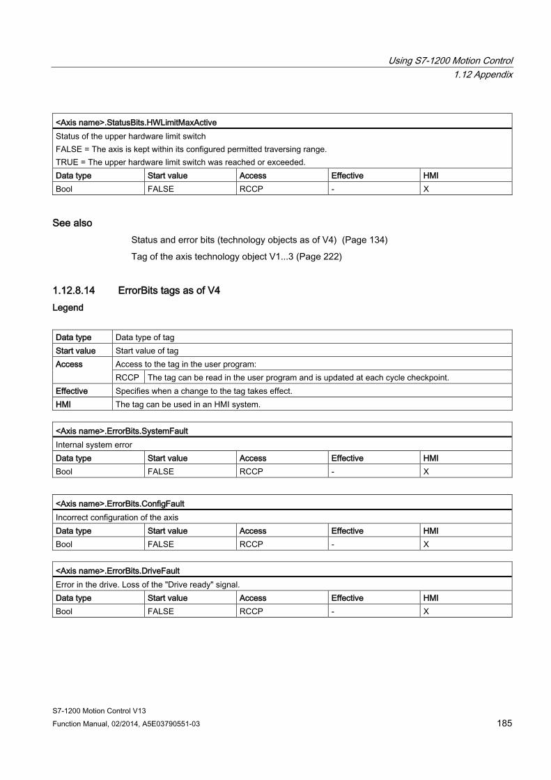
Using S7-1200 Motion Control 1.12 Appendix
S7-1200 Motion Control V13 Function Manual, 02/2014, A5E03790551-03 185
<Axis name>.StatusBits.HWLimitMaxActive Status of the upper hardware limit switch FALSE = The axis is kept within its configured permitted traversing range. TRUE = The upper hardware limit switch was reached or exceeded. Data type Start value Access Effective HMI Bool FALSE RCCP - X
See also Status and error bits (technology objects as of V4) (Page 134)
Tag of the axis technology object V1...3 (Page 222)
1.12.8.14 ErrorBits tags as of V4 Legend
Data type Data type of tag Start value Start value of tag Access Access to the tag in the user program:
RCCP The tag can be read in the user program and is updated at each cycle checkpoint. Effective Specifies when a change to the tag takes effect. HMI The tag can be used in an HMI system.
<Axis name>.ErrorBits.SystemFault Internal system error Data type Start value Access Effective HMI Bool FALSE RCCP - X
<Axis name>.ErrorBits.ConfigFault Incorrect configuration of the axis Data type Start value Access Effective HMI Bool FALSE RCCP - X
<Axis name>.ErrorBits.DriveFault Error in the drive. Loss of the "Drive ready" signal. Data type Start value Access Effective HMI Bool FALSE RCCP - X

Using S7-1200 Motion Control 1.12 Appendix
S7-1200 Motion Control V13 186 Function Manual, 02/2014, A5E03790551-03
<Axis name>.ErrorBits.SWLimit Software limit switch reached or exceeded Data type Start value Access Effective HMI Bool FALSE RCCP - X
<Axis name>.ErrorBits.HWLimit Hardware limit switch reached or exceeded Data type Start value Access Effective HMI Bool FALSE RCCP - X
<Axis name>.ErrorBits.DirectionFault Impermissible motion direction Data type Start value Access Effective HMI Bool FALSE RCCP - X
<Axis name>.ErrorBits.HWUsed Another axis is using the same PTO (Pulse Train Output) and is enabled with "MC_Power". Data type Start value Access Effective HMI Bool FALSE RCCP - X
See also Status and error bits (technology objects as of V4) (Page 134)
Tag of the axis technology object V1...3 (Page 222)
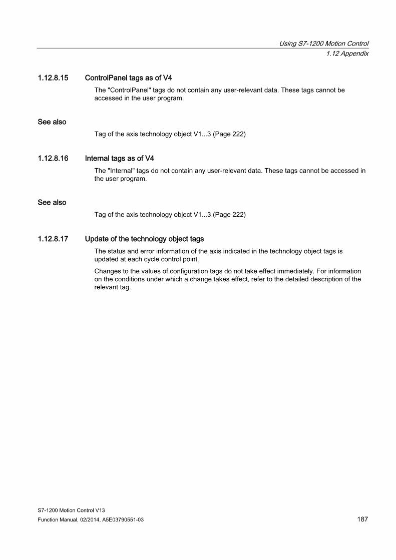
Using S7-1200 Motion Control 1.12 Appendix
S7-1200 Motion Control V13 Function Manual, 02/2014, A5E03790551-03 187
1.12.8.15 ControlPanel tags as of V4 The "ControlPanel" tags do not contain any user-relevant data. These tags cannot be accessed in the user program.
See also Tag of the axis technology object V1...3 (Page 222)
1.12.8.16 Internal tags as of V4 The "Internal" tags do not contain any user-relevant data. These tags cannot be accessed in the user program.
See also Tag of the axis technology object V1...3 (Page 222)
1.12.8.17 Update of the technology object tags The status and error information of the axis indicated in the technology object tags is updated at each cycle control point.
Changes to the values of configuration tags do not take effect immediately. For information on the conditions under which a change takes effect, refer to the detailed description of the relevant tag.

Using S7-1200 Motion Control 1.12 Appendix
S7-1200 Motion Control V13 188 Function Manual, 02/2014, A5E03790551-03
1.12.9 Tags of the command table technology object as of V4
1.12.9.1 Command[1...32] tags as of V4 Legend
Data type Data type of tag Start value Start value of tag
The start value can be overwritten by the configuration of the command table. Access Access to the tag in the user program:
RW The tag can be read and written in the user program. R The tag can be read in the user program. - The tag cannot be used in the user program.
Effective Specifies when a change to the tag takes effect. HMI The tag can be used in an HMI system.
<Command table>.Command[n].Type Command type • 0 = "Empty" command • 2 = "Hold" command • 5 = "Relative positioning" command • 6 = "Absolute positioning" command • 7 = "Velocity setpoint" command • 151 = "Wait" command
Data type Start value Access Effective HMI Int 0 RW - X
<Command table>.Command[n].Position Target position/traversing distance of the command Data type Start value Access Effective HMI Real 0.0 RW - X
<Axis name>.Command[n].Velocity Command velocity Data type Start value Access Effective HMI Real 0.0 RW - X
<Command table>.Command[n].Duration Command duration Data type Start value Access Effective HMI Real 0.0 RW - X
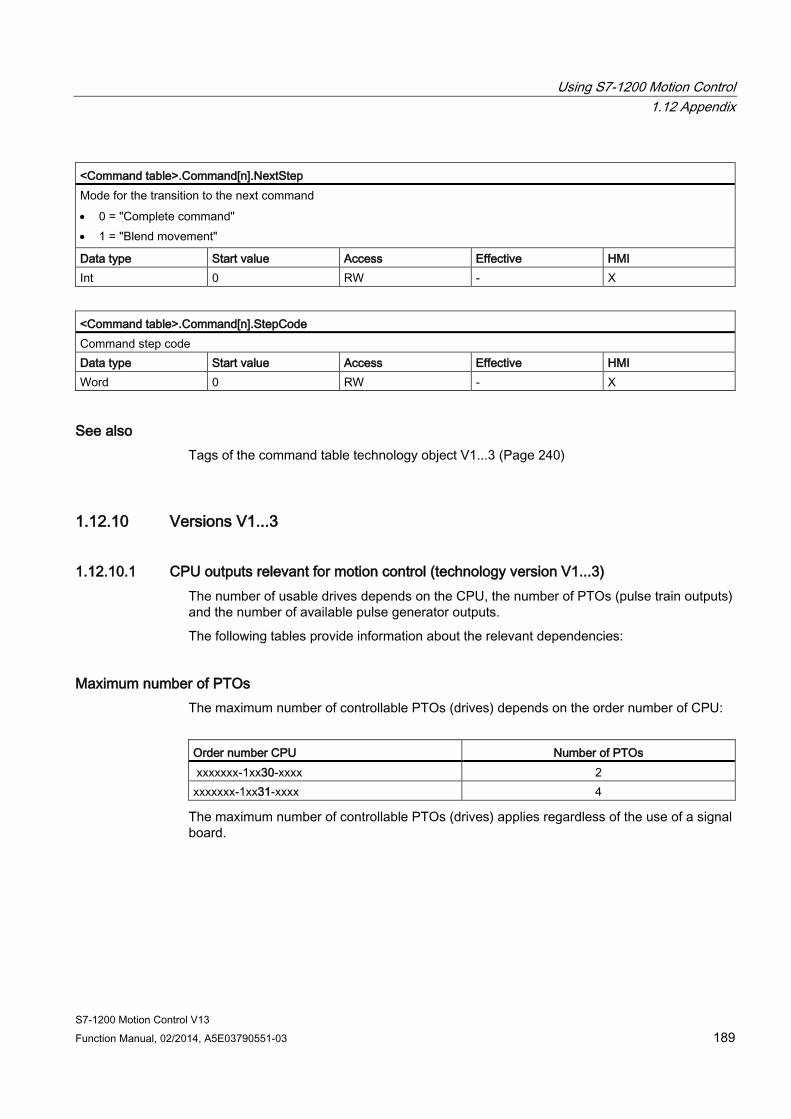
Using S7-1200 Motion Control 1.12 Appendix
S7-1200 Motion Control V13 Function Manual, 02/2014, A5E03790551-03 189
<Command table>.Command[n].NextStep Mode for the transition to the next command • 0 = "Complete command" • 1 = "Blend movement"
Data type Start value Access Effective HMI Int 0 RW - X
<Command table>.Command[n].StepCode Command step code Data type Start value Access Effective HMI Word 0 RW - X
See also Tags of the command table technology object V1...3 (Page 240)
1.12.10 Versions V1...3
1.12.10.1 CPU outputs relevant for motion control (technology version V1...3) The number of usable drives depends on the CPU, the number of PTOs (pulse train outputs) and the number of available pulse generator outputs.
The following tables provide information about the relevant dependencies:
Maximum number of PTOs The maximum number of controllable PTOs (drives) depends on the order number of CPU:
Order number CPU Number of PTOs xxxxxxx-1xx30-xxxx 2 xxxxxxx-1xx31-xxxx 4
The maximum number of controllable PTOs (drives) applies regardless of the use of a signal board.
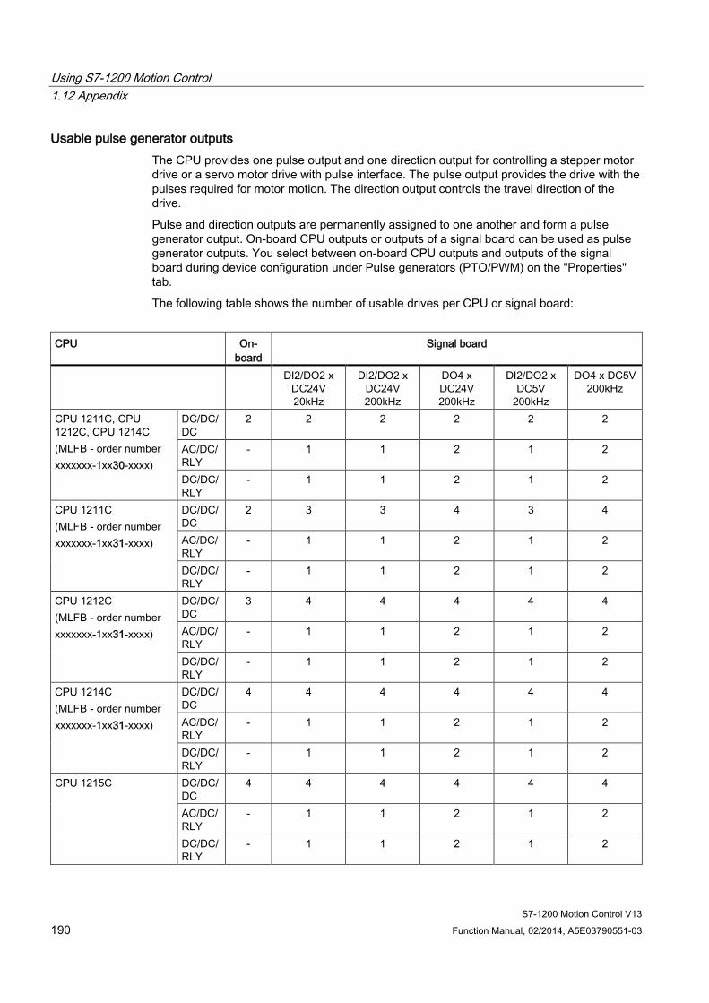
Using S7-1200 Motion Control 1.12 Appendix
S7-1200 Motion Control V13 190 Function Manual, 02/2014, A5E03790551-03
Usable pulse generator outputs The CPU provides one pulse output and one direction output for controlling a stepper motor drive or a servo motor drive with pulse interface. The pulse output provides the drive with the pulses required for motor motion. The direction output controls the travel direction of the drive.
Pulse and direction outputs are permanently assigned to one another and form a pulse generator output. On-board CPU outputs or outputs of a signal board can be used as pulse generator outputs. You select between on-board CPU outputs and outputs of the signal board during device configuration under Pulse generators (PTO/PWM) on the "Properties" tab.
The following table shows the number of usable drives per CPU or signal board:
CPU On-
board Signal board
DI2/DO2 x DC24V 20kHz
DI2/DO2 x DC24V 200kHz
DO4 x DC24V 200kHz
DI2/DO2 x DC5V
200kHz
DO4 x DC5V 200kHz
CPU 1211C, CPU 1212C, CPU 1214C (MLFB - order number xxxxxxx-1xx30-xxxx)
DC/DC/DC
2 2 2 2 2 2
AC/DC/RLY
- 1 1 2 1 2
DC/DC/RLY
- 1 1 2 1 2
CPU 1211C (MLFB - order number xxxxxxx-1xx31-xxxx)
DC/DC/DC
2 3 3 4 3 4
AC/DC/RLY
- 1 1 2 1 2
DC/DC/RLY
- 1 1 2 1 2
CPU 1212C (MLFB - order number xxxxxxx-1xx31-xxxx)
DC/DC/DC
3 4 4 4 4 4
AC/DC/RLY
- 1 1 2 1 2
DC/DC/RLY
- 1 1 2 1 2
CPU 1214C (MLFB - order number xxxxxxx-1xx31-xxxx)
DC/DC/DC
4 4 4 4 4 4
AC/DC/RLY
- 1 1 2 1 2
DC/DC/RLY
- 1 1 2 1 2
CPU 1215C DC/DC/DC
4 4 4 4 4 4
AC/DC/RLY
- 1 1 2 1 2
DC/DC/RLY
- 1 1 2 1 2
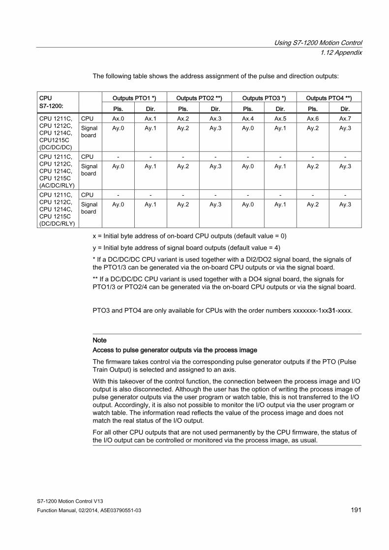
Using S7-1200 Motion Control 1.12 Appendix
S7-1200 Motion Control V13 Function Manual, 02/2014, A5E03790551-03 191
The following table shows the address assignment of the pulse and direction outputs:
CPU S7-1200:
Outputs PTO1 *) Outputs PTO2 **) Outputs PTO3 *) Outputs PTO4 **)
Pls. Dir. Pls. Dir. Pls. Dir. Pls. Dir. CPU 1211C, CPU 1212C, CPU 1214C, CPU1215C (DC/DC/DC)
CPU Ax.0 Ax.1 Ax.2 Ax.3 Ax.4 Ax.5 Ax.6 Ax.7 Signal board
Ay.0 Ay.1 Ay.2 Ay.3 Ay.0 Ay.1 Ay.2 Ay.3
CPU 1211C, CPU 1212C, CPU 1214C, CPU 1215C (AC/DC/RLY)
CPU - - - - - - - - Signal board
Ay.0 Ay.1 Ay.2 Ay.3 Ay.0 Ay.1 Ay.2 Ay.3
CPU 1211C, CPU 1212C, CPU 1214C, CPU 1215C (DC/DC/RLY)
CPU - - - - - - - - Signal board
Ay.0 Ay.1 Ay.2 Ay.3 Ay.0 Ay.1 Ay.2 Ay.3
x = Initial byte address of on-board CPU outputs (default value = 0)
y = Initial byte address of signal board outputs (default value = 4)
* If a DC/DC/DC CPU variant is used together with a DI2/DO2 signal board, the signals of the PTO1/3 can be generated via the on-board CPU outputs or via the signal board.
** If a DC/DC/DC CPU variant is used together with a DO4 signal board, the signals for PTO1/3 or PTO2/4 can be generated via the on-board CPU outputs or via the signal board.
PTO3 and PTO4 are only available for CPUs with the order numbers xxxxxxx-1xx31-xxxx.
Note Access to pulse generator outputs via the process image
The firmware takes control via the corresponding pulse generator outputs if the PTO (Pulse Train Output) is selected and assigned to an axis.
With this takeover of the control function, the connection between the process image and I/O output is also disconnected. Although the user has the option of writing the process image of pulse generator outputs via the user program or watch table, this is not transferred to the I/O output. Accordingly, it is also not possible to monitor the I/O output via the user program or watch table. The information read reflects the value of the process image and does not match the real status of the I/O output.
For all other CPU outputs that are not used permanently by the CPU firmware, the status of the I/O output can be controlled or monitored via the process image, as usual.
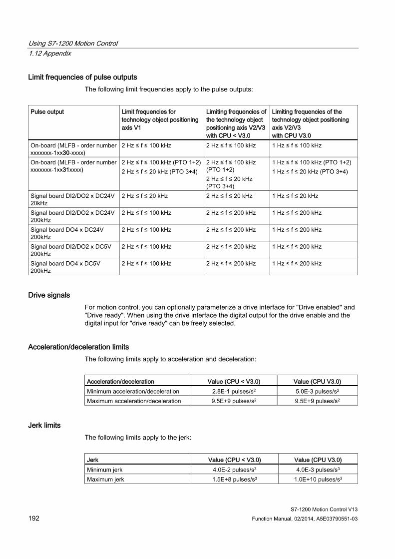
Using S7-1200 Motion Control 1.12 Appendix
S7-1200 Motion Control V13 192 Function Manual, 02/2014, A5E03790551-03
Limit frequencies of pulse outputs The following limit frequencies apply to the pulse outputs:
Pulse output Limit frequencies for
technology object positioning axis V1
Limiting frequencies of the technology object positioning axis V2/V3 with CPU < V3.0
Limiting frequencies of the technology object positioning axis V2/V3 with CPU V3.0
On-board (MLFB - order number xxxxxxx-1xx30-xxxx)
2 Hz ≤ f ≤ 100 kHz 2 Hz ≤ f ≤ 100 kHz 1 Hz ≤ f ≤ 100 kHz
On-board (MLFB - order number xxxxxxx-1xx31xxxx)
2 Hz ≤ f ≤ 100 kHz (PTO 1+2) 2 Hz ≤ f ≤ 20 kHz (PTO 3+4)
2 Hz ≤ f ≤ 100 kHz (PTO 1+2) 2 Hz ≤ f ≤ 20 kHz (PTO 3+4)
1 Hz ≤ f ≤ 100 kHz (PTO 1+2) 1 Hz ≤ f ≤ 20 kHz (PTO 3+4)
Signal board DI2/DO2 x DC24V 20kHz
2 Hz ≤ f ≤ 20 kHz 2 Hz ≤ f ≤ 20 kHz 1 Hz ≤ f ≤ 20 kHz
Signal board DI2/DO2 x DC24V 200kHz
2 Hz ≤ f ≤ 100 kHz 2 Hz ≤ f ≤ 200 kHz 1 Hz ≤ f ≤ 200 kHz
Signal board DO4 x DC24V 200kHz
2 Hz ≤ f ≤ 100 kHz 2 Hz ≤ f ≤ 200 kHz 1 Hz ≤ f ≤ 200 kHz
Signal board DI2/DO2 x DC5V 200kHz
2 Hz ≤ f ≤ 100 kHz 2 Hz ≤ f ≤ 200 kHz 1 Hz ≤ f ≤ 200 kHz
Signal board DO4 x DC5V 200kHz
2 Hz ≤ f ≤ 100 kHz 2 Hz ≤ f ≤ 200 kHz 1 Hz ≤ f ≤ 200 kHz
Drive signals For motion control, you can optionally parameterize a drive interface for "Drive enabled" and "Drive ready". When using the drive interface the digital output for the drive enable and the digital input for "drive ready" can be freely selected.
Acceleration/deceleration limits The following limits apply to acceleration and deceleration:
Acceleration/deceleration Value (CPU < V3.0) Value (CPU V3.0) Minimum acceleration/deceleration 2.8E-1 pulses/s2 5.0E-3 pulses/s2 Maximum acceleration/deceleration 9.5E+9 pulses/s2 9.5E+9 pulses/s2
Jerk limits The following limits apply to the jerk:
Jerk Value (CPU < V3.0) Value (CPU V3.0) Minimum jerk 4.0E-2 pulses/s3 4.0E-3 pulses/s3 Maximum jerk 1.5E+8 pulses/s3 1.0E+10 pulses/s3
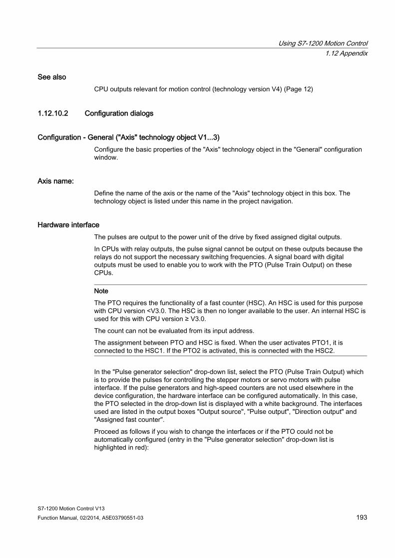
Using S7-1200 Motion Control 1.12 Appendix
S7-1200 Motion Control V13 Function Manual, 02/2014, A5E03790551-03 193
See also CPU outputs relevant for motion control (technology version V4) (Page 12)
1.12.10.2 Configuration dialogs
Configuration - General ("Axis" technology object V1...3) Configure the basic properties of the "Axis" technology object in the "General" configuration window.
Axis name: Define the name of the axis or the name of the "Axis" technology object in this box. The technology object is listed under this name in the project navigation.
Hardware interface The pulses are output to the power unit of the drive by fixed assigned digital outputs.
In CPUs with relay outputs, the pulse signal cannot be output on these outputs because the relays do not support the necessary switching frequencies. A signal board with digital outputs must be used to enable you to work with the PTO (Pulse Train Output) on these CPUs.
Note
The PTO requires the functionality of a fast counter (HSC). An HSC is used for this purpose with CPU version <V3.0. The HSC is then no longer available to the user. An internal HSC is used for this with CPU version ≥ V3.0.
The count can not be evaluated from its input address.
The assignment between PTO and HSC is fixed. When the user activates PTO1, it is connected to the HSC1. If the PTO2 is activated, this is connected with the HSC2.
In the "Pulse generator selection" drop-down list, select the PTO (Pulse Train Output) which is to provide the pulses for controlling the stepper motors or servo motors with pulse interface. If the pulse generators and high-speed counters are not used elsewhere in the device configuration, the hardware interface can be configured automatically. In this case, the PTO selected in the drop-down list is displayed with a white background. The interfaces used are listed in the output boxes "Output source", "Pulse output", "Direction output" and "Assigned fast counter".
Proceed as follows if you wish to change the interfaces or if the PTO could not be automatically configured (entry in the "Pulse generator selection" drop-down list is highlighted in red):
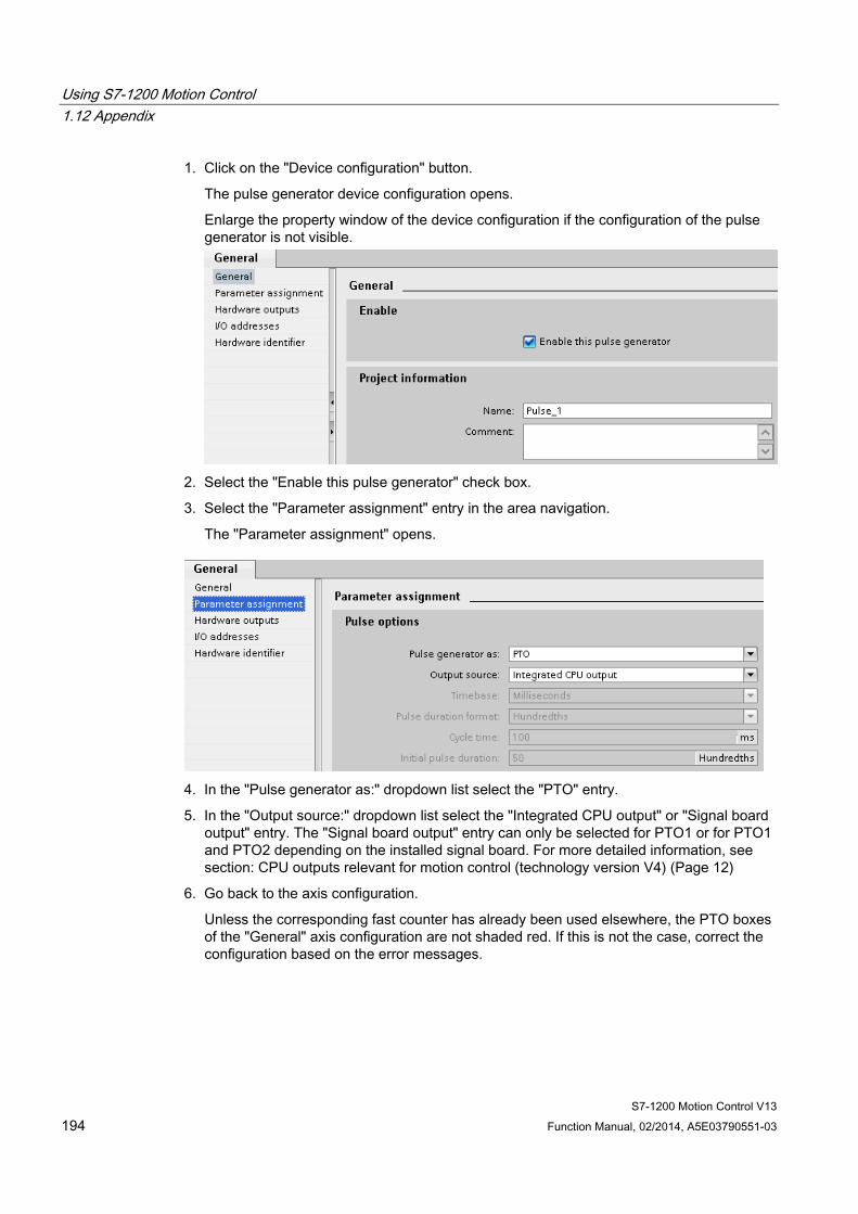
Using S7-1200 Motion Control 1.12 Appendix
S7-1200 Motion Control V13 194 Function Manual, 02/2014, A5E03790551-03
1. Click on the "Device configuration" button.
The pulse generator device configuration opens.
Enlarge the property window of the device configuration if the configuration of the pulse generator is not visible.
2. Select the "Enable this pulse generator" check box.
3. Select the "Parameter assignment" entry in the area navigation.
The "Parameter assignment" opens.
4. In the "Pulse generator as:" dropdown list select the "PTO" entry.
5. In the "Output source:" dropdown list select the "Integrated CPU output" or "Signal board output" entry. The "Signal board output" entry can only be selected for PTO1 or for PTO1 and PTO2 depending on the installed signal board. For more detailed information, see section: CPU outputs relevant for motion control (technology version V4) (Page 12)
6. Go back to the axis configuration.
Unless the corresponding fast counter has already been used elsewhere, the PTO boxes of the "General" axis configuration are not shaded red. If this is not the case, correct the configuration based on the error messages.
Using S7-1200 Motion Control 1.12 Appendix
S7-1200 Motion Control V13 Function Manual, 02/2014, A5E03790551-03 195
User unit Select the desired unit for the dimension system of the axis in the dropdown list. The selected unit is used for additional configuration of the "Axis" technology object and for displaying the current axis data.
The values at the input parameters (Position, Distance, Velocity, ...) of the Motion Control instructions also refer to this unit.
Note
Later changing of the dimension system may not be converted correctly in all the configuration windows of the technology object. In this case check the configuration of all axis parameters.
The values of the input parameters of the Motion Control instructions may have to be adapted to the new unit of measurement in the user program.
See also Configuration - General (positioning axis technology object as of V4) (Page 40)
Changing configuration of dynamic values in user program ("Axis" technology object V1...3) You can change the following configuration parameters during runtime of the user program in the CPU:
Acceleration and deceleration You can also change the values for acceleration and deceleration during runtime of the user program. Use the following technology object tags for this purpose:
● <Axis name>.Config.DynamicDefaults.Acceleration
for changing acceleration
● <Axis name>.Config.DynamicDefaults.Deceleration
for changing deceleration
Refer to the description of the technology object tags (Page 222) in the appendix for information on when changes to the configuration parameters take effect.
Using S7-1200 Motion Control 1.12 Appendix
S7-1200 Motion Control V13 196 Function Manual, 02/2014, A5E03790551-03
Emergency stop deceleration You can also change the value for the emergency stop deceleration during runtime of the user program. Use the following technology object tag for this purpose:
● <Axis name>.Config.DynamicDefaults.EmergencyDeceleration
Refer to the description of the technology object tags in the appendix for information on when changes to the configuration parameter take effect.
NOTICE
After changes to this parameter, it may be necessary to adapt the positions of the hardware limit switches and other safety-relevant settings.
Jerk limit (as of technology object "Axis" V2.0) You can also activate and deactivate the jerk limit at runtime of the user program and change the value for the jerk. Use the following technology object tags for this purpose:
● <Axis name>.Config.DynamicDefaults.JerkActive
for activating and deactivating the jerk limit
● <Axis name>.Config.DynamicDefaults.Jerk
for changing the jerk
Refer to the description of the technology object tags in the appendix for information on when changes to the configuration parameter take effect.
See also Changing the configuration of dynamics in the user program (Page 56)
Configuration - Homing ("Axis" technology object V1) Configure the parameters for active and passive homing in the "Homing" configuration window. The homing method is set using the "Mode" input parameter of the Motion Control instruction. Here, Mode = 2 means passive homing and Mode = 3 means active homing.

Using S7-1200 Motion Control 1.12 Appendix
S7-1200 Motion Control V13 Function Manual, 02/2014, A5E03790551-03 197
Reference point switch input Select the digital input for the reference point switch from the drop-down list. The input must be interrupt-capable. The onboard CPU inputs and the inputs of an inserted signal board can be selected as inputs for the reference point switch.
Note
The digital inputs are set to a filter time of 6.4 ms by default.
When the digital inputs are used as a reference point switch, this can result in undesired decelerations and thus inaccuracies. Depending on the homing velocity and extent of the reference point switch, the reference point may not be detected. The filter time can be set under "Input filter" in the device configuration of the digital inputs.
The specified filter time must be less than the duration of the input signal at the reference point switch.
Permitting direction reversal after reaching the HW limit switch (active homing only) Activate the check box to use the hardware limit switch as a reversing cam for the homing procedure. The hardware limit switches must be activated for direction reversal. If the CPU firmware V1.0 is used, both hardware limit switches must be configured. If CPU firmware as of V2.0 is used, only the hardware limit switch in the approach direction must be configured.
If the hardware limit switch is reached during active homing, the axis brakes at the configured deceleration (not with the emergency stop deceleration) and reverses direction. The reference point switch is then sensed in reverse direction.
If the direction reversal is not active and the axis reaches the hardware limit switch during active homing, the homing procedure is aborted with an error and the axis is braked at the emergency stop deceleration.
Note
Use one of the following measures to ensure that the machine does not travel to a mechanical endstop in the event of a direction reversal: • Keep the approach velocity low • Increase the configured acceleration/deceleration • Increase the distance between hardware limit switch and mechanical stop
Approach / homing direction (active and passive homing) With the direction selection, you determine the "approach direction" used during active homing to search for the reference point switch, as well as the homing direction. The homing direction specifies the travel direction the axis uses to approach the configured end of the reference point switch to carry out the homing operation.
Refer to the table under "Reference point switches" for the effect of the approach direction setting on passive homing.
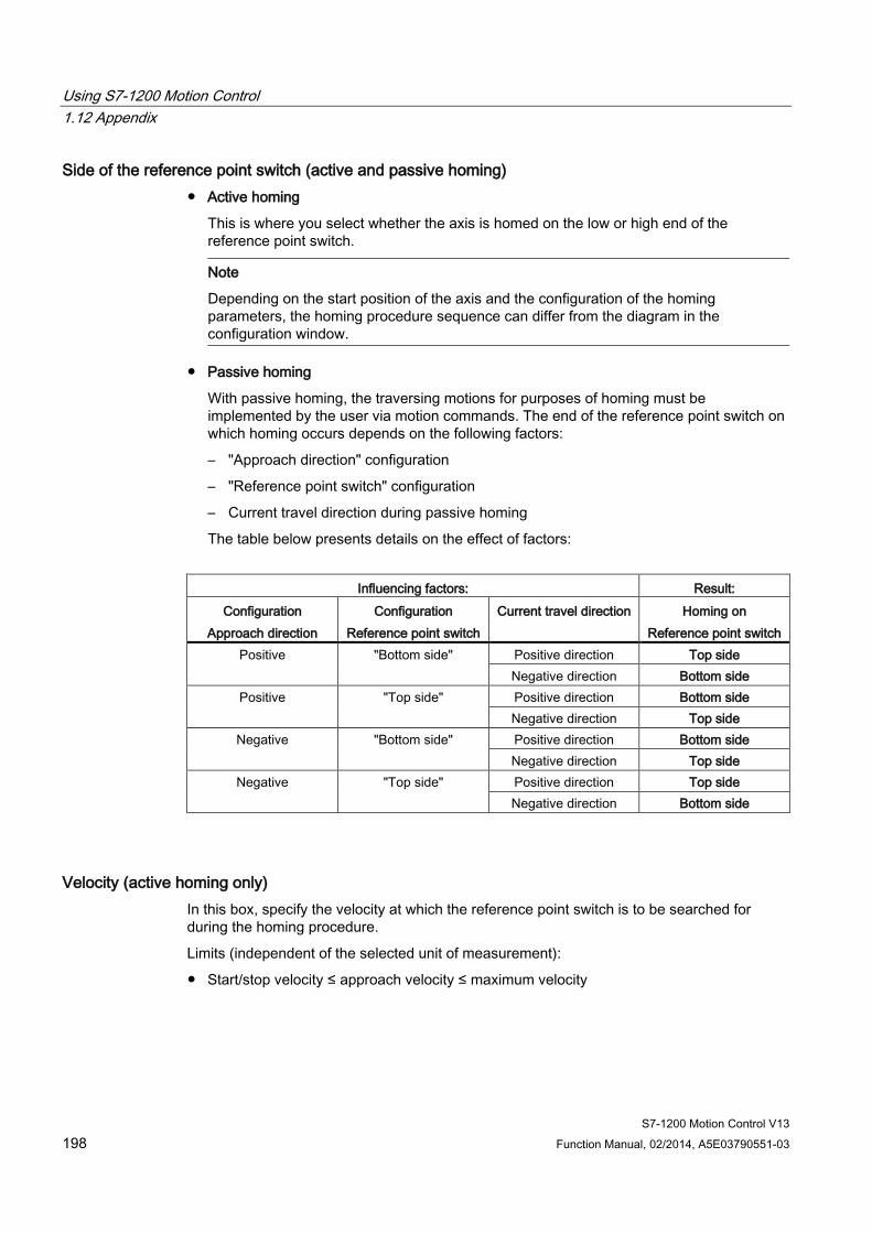
Using S7-1200 Motion Control 1.12 Appendix
S7-1200 Motion Control V13 198 Function Manual, 02/2014, A5E03790551-03
Side of the reference point switch (active and passive homing) ● Active homing
This is where you select whether the axis is homed on the low or high end of the reference point switch.
Note
Depending on the start position of the axis and the configuration of the homing parameters, the homing procedure sequence can differ from the diagram in the configuration window.
● Passive homing
With passive homing, the traversing motions for purposes of homing must be implemented by the user via motion commands. The end of the reference point switch on which homing occurs depends on the following factors:
– "Approach direction" configuration
– "Reference point switch" configuration
– Current travel direction during passive homing
The table below presents details on the effect of factors:
Influencing factors: Result:
Configuration Approach direction
Configuration Reference point switch
Current travel direction Homing on Reference point switch
Positive "Bottom side" Positive direction Top side Negative direction Bottom side
Positive "Top side" Positive direction Bottom side Negative direction Top side
Negative "Bottom side" Positive direction Bottom side Negative direction Top side
Negative "Top side" Positive direction Top side Negative direction Bottom side
Velocity (active homing only) In this box, specify the velocity at which the reference point switch is to be searched for during the homing procedure.
Limits (independent of the selected unit of measurement):
● Start/stop velocity ≤ approach velocity ≤ maximum velocity
Using S7-1200 Motion Control 1.12 Appendix
S7-1200 Motion Control V13 Function Manual, 02/2014, A5E03790551-03 199
Homing velocity (active homing only) In this box, specify the velocity at which the axis approaches the reference point switch for homing.
Limits (independent of the selected unit of measurement):
● Start/stop velocity ≤ Homing velocity ≤ Maximum velocity
Home position offset (active homing only) If the desired home position deviates from the position of the reference point switch, the home position offset can be specified in this box.
If the value does not equal 0, the axis executes the following actions following homing at the reference point switch:
1. Move the axis at the homing velocity by the value of the home position offset
2. Upon reaching the "home position offset", the axis is at the home position that was specified in input parameter "Position" of the "MC_Home" Motion Control instruction.
Limits (independent of the selected unit of measurement):
● -1.0e12 ≤ home position offset ≤ 1.0e12
Home position The position configured in the Motion Control instruction "MC_Home" is used as the home position.
Using S7-1200 Motion Control 1.12 Appendix
S7-1200 Motion Control V13 200 Function Manual, 02/2014, A5E03790551-03
Configuration - Homing ("Axis" technology object V2...3)
Configuration - Homing - General (Axis technology object V2...3) Configure the reference point switch input for active and passive homing in the "Homing - General" configuration window.
Reference point switch input Select the digital input for the homing switch from the drop-down list. The input must be interrupt-capable. The on-board CPU inputs and the inputs of an inserted signal board can be selected as inputs for the homing switch.
Note
The digital inputs are set to a filter time of 6.4 ms by default.
When the digital inputs are used as a homing switch, this can result in undesired decelerations and thus inaccuracies. Depending on the homing velocity and extent of the homing switch, the home position may not be detected. The filter time can be set under "Input filter" in the device configuration of the digital inputs.
The specified filter time must be less than the duration of the input signal at the homing switch.
Active level In the drop-list, select the level of the homing switch that is to be used for homing.
See also Sequence - Active homing (Page 62)
Configuration - Homing - Passive (Axis technology object V2...3) Configure the necessary parameters for passive homing in the "Homing - Passive" configuration window.
The movement for passive homing must be triggered by the user (e.g. using an axis motion command). Passive homing is started using Motion Control instruction "MC_Home" with input parameter "Mode" = 2.
Side of the homing switch This is where you select whether the axis is to be homed on the low or high end of the homing switch.
Using S7-1200 Motion Control 1.12 Appendix
S7-1200 Motion Control V13 Function Manual, 02/2014, A5E03790551-03 201
Home position The position configured in the Motion Control instruction "MC_Home" is used as the home position.
Note
If passive homing is carried out without an axis motion command (axis at a standstill), homing will be executed upon the next rising or falling edge at the homing switch.
Configuration - Homing - Active (Axis technology object V2...3) Configure the necessary parameters for active homing in the "Active homing" configuration window. Active homing is started using Motion Control instruction "MC_Home" with input parameter "Mode" = 3.
Permit auto reverse at the hardware limit switch Activate the check box to use the hardware limit switch as a reversing cam for the homing procedure. The hardware limit switches must be enabled for the reversal of direction (at least the hardware limit switch in the direction of approach must be configured).
If the hardware limit switch is reached during active homing, the axis brakes at the configured deceleration (not with the emergency stop deceleration) and reverses direction. The homing switch is then sensed in reverse direction.
If the direction reversal is not active and the axis reaches the hardware limit switch during active homing, the homing procedure is aborted with an error and the axis is braked at the emergency stop deceleration.
Note
If possible, use one of the following measures to ensure that the machine does not travel to a mechanical endstop in the event of a direction reversal: • Keep the approach velocity low. • Increase the configured acceleration/deceleration. • Increase the distance between the hardware limit switch and the mechanical endstop.
Approach/homing direction With the direction selection, you determine the approach direction used during active homing to search for the homing switch, as well as the homing direction. The homing direction specifies the travel direction the axis uses to approach the configured end of the homing switch to carry out the homing operation.
Side of the homing switch This is where you select whether the axis is to be homed on the low or high end of the homing switch.

Using S7-1200 Motion Control 1.12 Appendix
S7-1200 Motion Control V13 202 Function Manual, 02/2014, A5E03790551-03
Velocity In this box, specify the velocity at which the homing switch is to be searched for during the homing procedure.
Limits (independent of the selected unit of measurement):
● Start/stop velocity ≤ approach velocity ≤ maximum velocity
Homing velocity In this box, specify the velocity at which the reference point switch is to be approached for homing.
Limits (independent of the selected unit of measurement):
● Start/stop velocity ≤ Homing velocity ≤ Maximum velocity
Home position offset If the desired home position deviates from the position of the homing switch, the home position offset can be specified in this box.
If the value does not equal 0, the axis executes the following actions following homing at the homing switch:
1. Move the axis at the homing velocity by the value of the home position offset
2. Upon reaching the "home position offset", the axis is at the home position that was specified in input parameter "Position" of the "MC_Home" Motion Control instruction.
Limits (independent of the selected unit of measurement):
● -1.0e12 ≤ home position offset ≤ 1.0e12
Home position The position configured in the Motion Control instruction "MC_Home" is used as the home position.
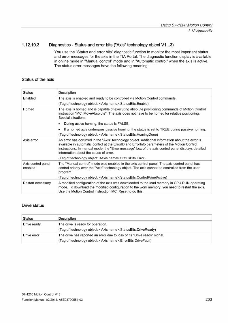
Using S7-1200 Motion Control 1.12 Appendix
S7-1200 Motion Control V13 Function Manual, 02/2014, A5E03790551-03 203
1.12.10.3 Diagnostics - Status and error bits ("Axis" technology object V1...3) You use the "Status and error bits" diagnostic function to monitor the most important status and error messages for the axis in the TIA Portal. The diagnostic function display is available in online mode in "Manual control" mode and in "Automatic control" when the axis is active. The status error messages have the following meaning:
Status of the axis Status Description Enabled The axis is enabled and ready to be controlled via Motion Control commands.
(Tag of technology object: <Axis name>.StatusBits.Enable) Homed The axis is homed and is capable of executing absolute positioning commands of Motion Control
instruction "MC_MoveAbsolute". The axis does not have to be homed for relative positioning. Special situations: • During active homing, the status is FALSE. • If a homed axis undergoes passive homing, the status is set to TRUE during passive homing. (Tag of technology object: <Axis name>.StatusBits.HomingDone)
Axis error An error has occurred in the "Axis" technology object. Additional information about the error is available in automatic control at the ErrorID and ErrorInfo parameters of the Motion Control instructions. In manual mode, the "Error message" box of the axis control panel displays detailed information about the cause of error. (Tag of technology object: <Axis name>.StatusBits.Error)
Axis control panel enabled
The "Manual control" mode was enabled in the axis control panel. The axis control panel has control priority over the "Axis" technology object. The axis cannot be controlled from the user program. (Tag of technology object: <Axis name>.StatusBits.ControlPanelActive)
Restart necessary A modified configuration of the axis was downloaded to the load memory in CPU RUN operating mode. To download the modified configuration to the work memory, you need to restart the axis. Use the Motion Control instruction MC_Reset to do this.
Drive status Status Description Drive ready The drive is ready for operation.
(Tag of technology object: <Axis name>.StatusBits.DriveReady) Drive error The drive has reported an error due to loss of its "Drive ready" signal.
(Tag of technology object: <Axis name>.ErrorBits.DriveFault)
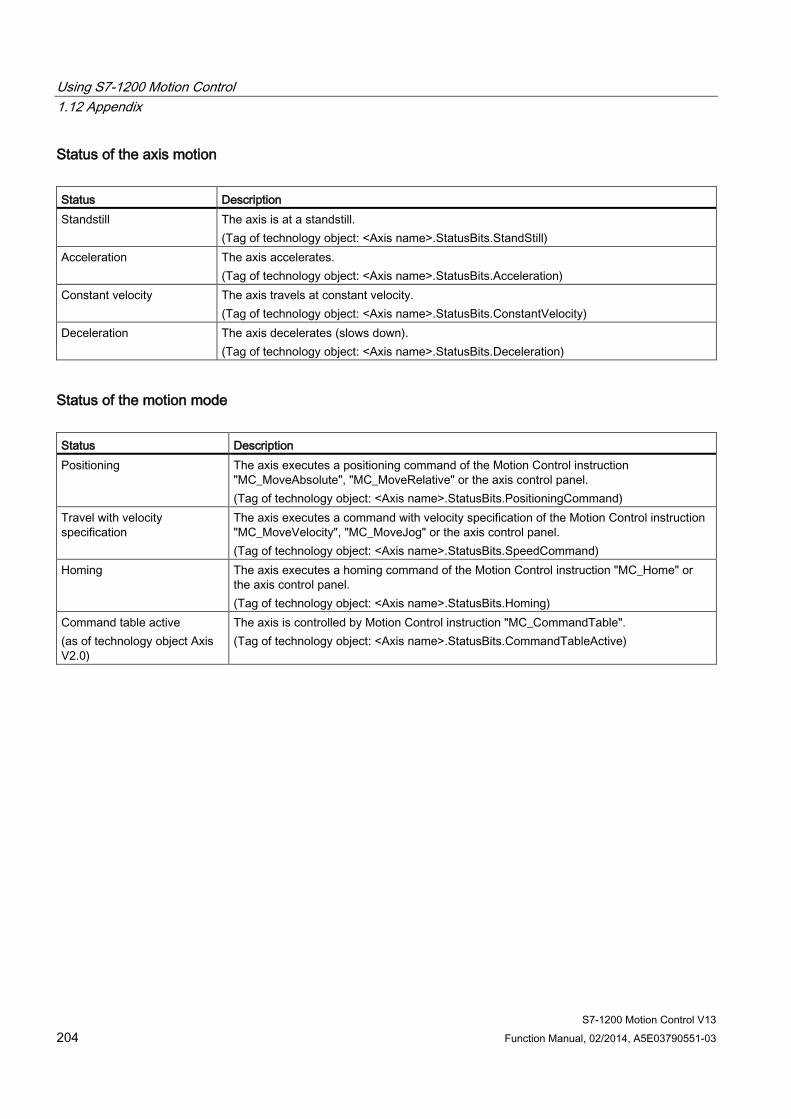
Using S7-1200 Motion Control 1.12 Appendix
S7-1200 Motion Control V13 204 Function Manual, 02/2014, A5E03790551-03
Status of the axis motion Status Description Standstill The axis is at a standstill.
(Tag of technology object: <Axis name>.StatusBits.StandStill) Acceleration The axis accelerates.
(Tag of technology object: <Axis name>.StatusBits.Acceleration) Constant velocity The axis travels at constant velocity.
(Tag of technology object: <Axis name>.StatusBits.ConstantVelocity) Deceleration The axis decelerates (slows down).
(Tag of technology object: <Axis name>.StatusBits.Deceleration)
Status of the motion mode Status Description Positioning The axis executes a positioning command of the Motion Control instruction
"MC_MoveAbsolute", "MC_MoveRelative" or the axis control panel. (Tag of technology object: <Axis name>.StatusBits.PositioningCommand)
Travel with velocity specification
The axis executes a command with velocity specification of the Motion Control instruction "MC_MoveVelocity", "MC_MoveJog" or the axis control panel. (Tag of technology object: <Axis name>.StatusBits.SpeedCommand)
Homing The axis executes a homing command of the Motion Control instruction "MC_Home" or the axis control panel. (Tag of technology object: <Axis name>.StatusBits.Homing)
Command table active (as of technology object Axis V2.0)
The axis is controlled by Motion Control instruction "MC_CommandTable". (Tag of technology object: <Axis name>.StatusBits.CommandTableActive)
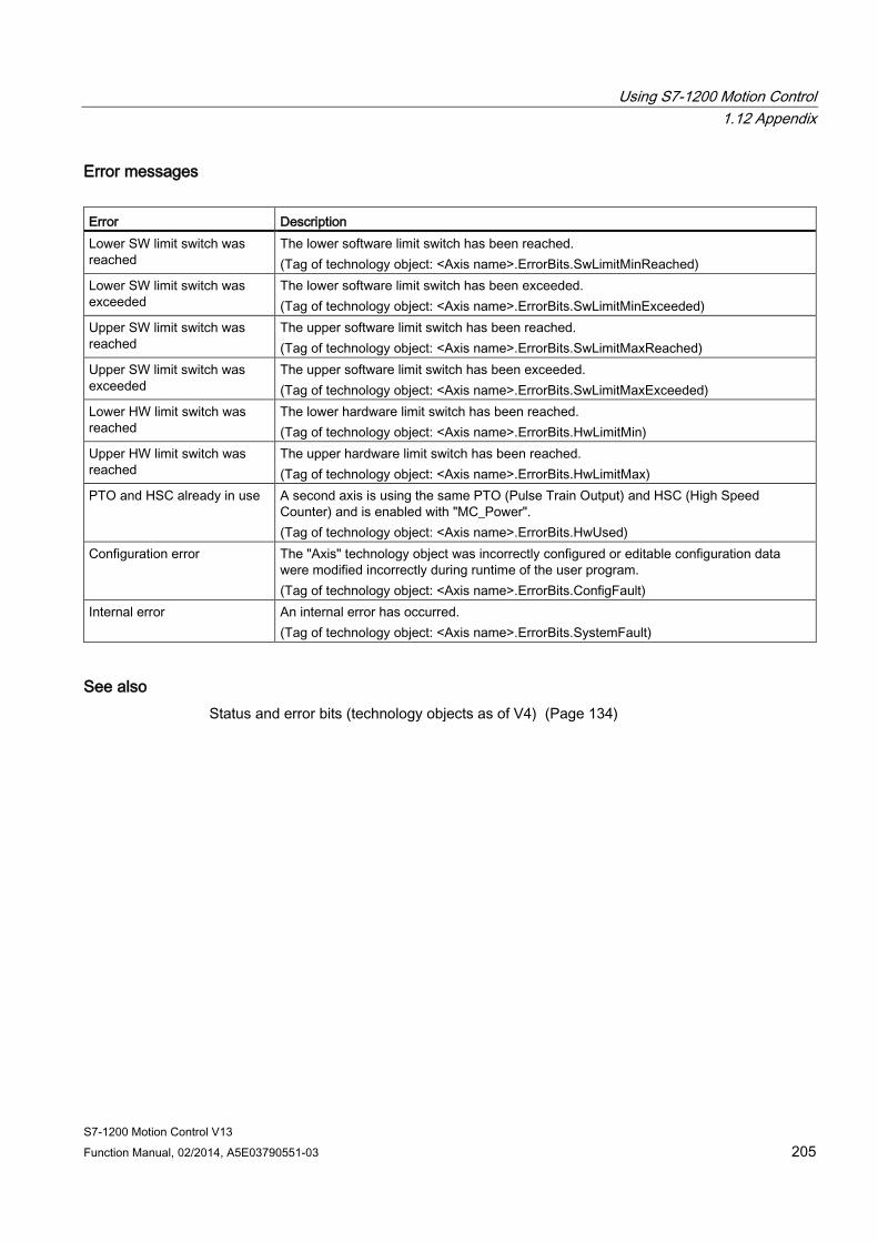
Using S7-1200 Motion Control 1.12 Appendix
S7-1200 Motion Control V13 Function Manual, 02/2014, A5E03790551-03 205
Error messages Error Description Lower SW limit switch was reached
The lower software limit switch has been reached. (Tag of technology object: <Axis name>.ErrorBits.SwLimitMinReached)
Lower SW limit switch was exceeded
The lower software limit switch has been exceeded. (Tag of technology object: <Axis name>.ErrorBits.SwLimitMinExceeded)
Upper SW limit switch was reached
The upper software limit switch has been reached. (Tag of technology object: <Axis name>.ErrorBits.SwLimitMaxReached)
Upper SW limit switch was exceeded
The upper software limit switch has been exceeded. (Tag of technology object: <Axis name>.ErrorBits.SwLimitMaxExceeded)
Lower HW limit switch was reached
The lower hardware limit switch has been reached. (Tag of technology object: <Axis name>.ErrorBits.HwLimitMin)
Upper HW limit switch was reached
The upper hardware limit switch has been reached. (Tag of technology object: <Axis name>.ErrorBits.HwLimitMax)
PTO and HSC already in use A second axis is using the same PTO (Pulse Train Output) and HSC (High Speed Counter) and is enabled with "MC_Power". (Tag of technology object: <Axis name>.ErrorBits.HwUsed)
Configuration error The "Axis" technology object was incorrectly configured or editable configuration data were modified incorrectly during runtime of the user program. (Tag of technology object: <Axis name>.ErrorBits.ConfigFault)
Internal error An internal error has occurred. (Tag of technology object: <Axis name>.ErrorBits.SystemFault)
See also Status and error bits (technology objects as of V4) (Page 134)
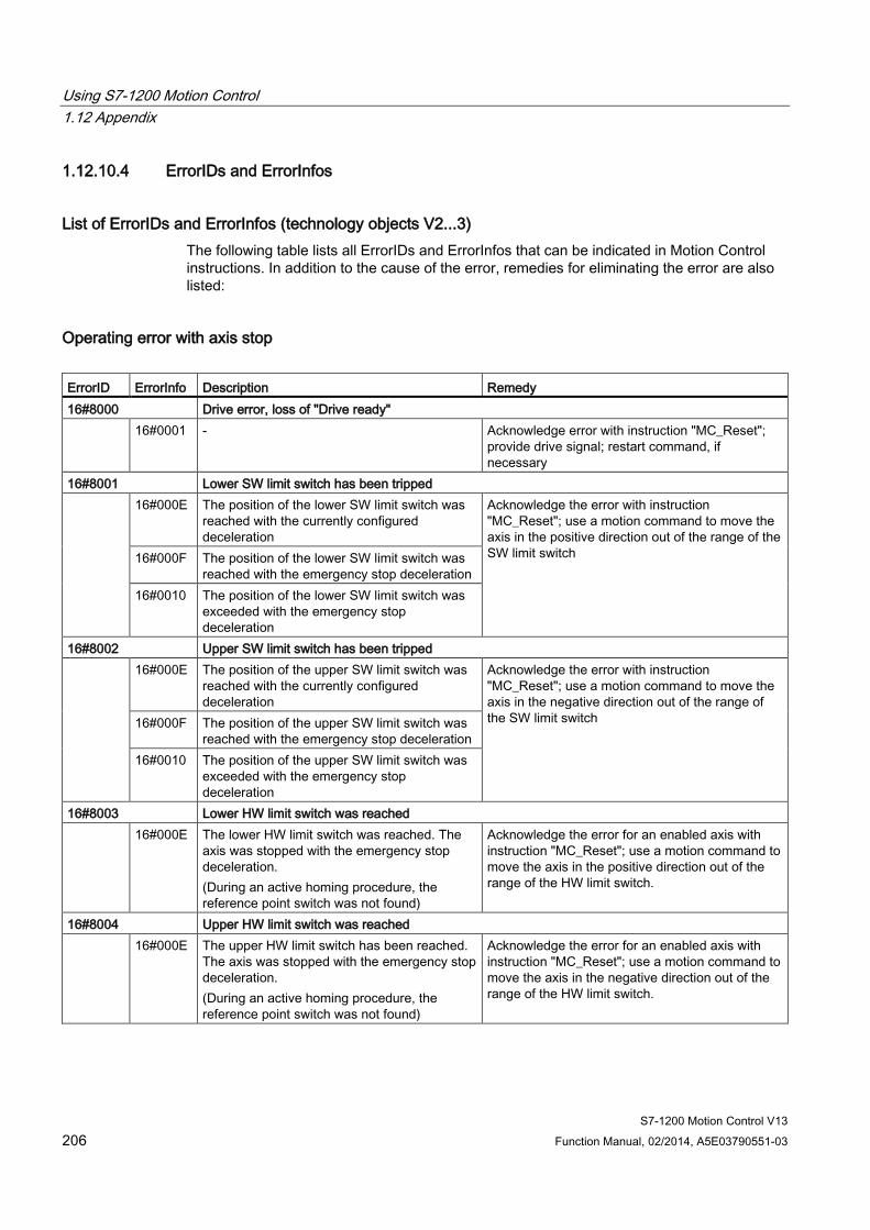
Using S7-1200 Motion Control 1.12 Appendix
S7-1200 Motion Control V13 206 Function Manual, 02/2014, A5E03790551-03
1.12.10.4 ErrorIDs and ErrorInfos
List of ErrorIDs and ErrorInfos (technology objects V2...3) The following table lists all ErrorIDs and ErrorInfos that can be indicated in Motion Control instructions. In addition to the cause of the error, remedies for eliminating the error are also listed:
Operating error with axis stop ErrorID ErrorInfo Description Remedy 16#8000 Drive error, loss of "Drive ready" 16#0001 - Acknowledge error with instruction "MC_Reset";
provide drive signal; restart command, if necessary
16#8001 Lower SW limit switch has been tripped 16#000E The position of the lower SW limit switch was
reached with the currently configured deceleration
Acknowledge the error with instruction "MC_Reset"; use a motion command to move the axis in the positive direction out of the range of the SW limit switch 16#000F The position of the lower SW limit switch was
reached with the emergency stop deceleration 16#0010 The position of the lower SW limit switch was
exceeded with the emergency stop deceleration
16#8002 Upper SW limit switch has been tripped 16#000E The position of the upper SW limit switch was
reached with the currently configured deceleration
Acknowledge the error with instruction "MC_Reset"; use a motion command to move the axis in the negative direction out of the range of the SW limit switch 16#000F The position of the upper SW limit switch was
reached with the emergency stop deceleration 16#0010 The position of the upper SW limit switch was
exceeded with the emergency stop deceleration
16#8003 Lower HW limit switch was reached 16#000E The lower HW limit switch was reached. The
axis was stopped with the emergency stop deceleration. (During an active homing procedure, the reference point switch was not found)
Acknowledge the error for an enabled axis with instruction "MC_Reset"; use a motion command to move the axis in the positive direction out of the range of the HW limit switch.
16#8004 Upper HW limit switch was reached 16#000E The upper HW limit switch has been reached.
The axis was stopped with the emergency stop deceleration. (During an active homing procedure, the reference point switch was not found)
Acknowledge the error for an enabled axis with instruction "MC_Reset"; use a motion command to move the axis in the negative direction out of the range of the HW limit switch.

Using S7-1200 Motion Control 1.12 Appendix
S7-1200 Motion Control V13 Function Manual, 02/2014, A5E03790551-03 207
ErrorID ErrorInfo Description Remedy 16#8005 PTO/HSC are already being used by another axis 16#0001 - The axis was configured incorrectly:
Correct the configuration of the PTO (Pulse Train Output) / HSC (High Speed Counter) and download it to the controller More than one axis is to run with one PTO: Another axis is using the PTO / HSC. If the current axis is to assume the control, the other axis must be disabled with "MC_Power" Enable = FALSE. (see also Using multiple axes with the same PTO (Page 139))
16#8006 A communication error in the control panel has occurred 16#0012 A timeout has occurred Check the cable connection and press the
"Manual control" button again. 16#8007 The axis cannot be enabled. 16#0025 Restarting Wait until the axis restart is complete. 16#0026 Executing loading process in RUN mode Wait until the loading process is complete.
Operating error without axis stop ErrorID ErrorInfo Description Remedy 16#8200 Axis is not enabled 16#0001 - Enable the axis; restart the command 16#8201 Axis has already been enabled by another "MC_Power" instance 16#0001 - Enable the axis with only one "MC_Power"
instance 16#8202 The maximum number of simultaneously active Motion Control commands has been exceeded
(maximum of 200 commands for all motion control technology objects) 16#0001 - Reduce the number of simultaneously active
commands; restart the command A command is active if parameter "Busy" = TRUE in the Motion Control instruction.
16#8203 Axis is currently operated in "Manual control" (axis control panel) 16#0001 - Exit "Manual control"; restart the command 16#8204 Axis is not homed 16#0001 - Home the axis with instruction "MC_Home"; restart
the command 16#8205 The axis is currently controlled by the user program (the error is only displayed in the axis control
panel) 16#0013 The axis is enabled in the user program. Disable axis with instruction "MC_Power" and
select "Manual control" again in the axis control panel
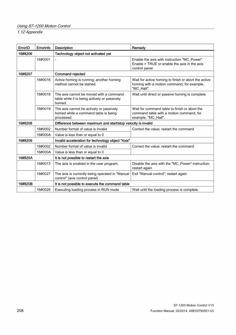
Using S7-1200 Motion Control 1.12 Appendix
S7-1200 Motion Control V13 208 Function Manual, 02/2014, A5E03790551-03
ErrorID ErrorInfo Description Remedy 16#8206 Technology object not activated yet 16#0001 - Enable the axis with instruction "MC_Power"
Enable = TRUE or enable the axis in the axis control panel.
16#8207 Command rejected 16#0016 Active homing is running; another homing
method cannot be started. Wait for active homing to finish or abort the active homing with a motion command, for example, "MC_Halt".
16#0018 The axis cannot be moved with a command table while it is being actively or passively homed.
Wait until direct or passive homing is complete.
16#0019 The axis cannot be actively or passively homed while a command table is being processed.
Wait for command table to finish or abort the command table with a motion command, for example, "MC_Halt".
16#8208 Difference between maximum and start/stop velocity is invalid 16#0002 Number format of value is invalid Correct the value; restart the command
16#000A Value is less than or equal to 0 16#8209 Invalid acceleration for technology object "Axis" 16#0002 Number format of value is invalid Correct the value; restart the command
16#000A Value is less than or equal to 0 16#820A It is not possible to restart the axis 16#0013 The axis is enabled in the user program. Disable the axis with the "MC_Power" instruction;
restart again 16#0027 The axis is currently being operated in "Manual
control" (axis control panel) Exit "Manual control"; restart again
16#820B It is not possible to execute the command table 16#0026 Executing loading process in RUN mode Wait until the loading process is complete.
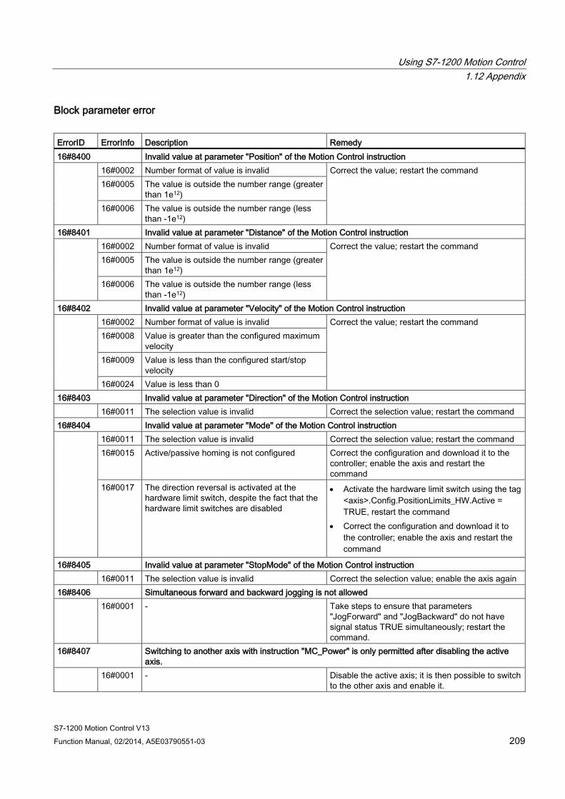
Using S7-1200 Motion Control 1.12 Appendix
S7-1200 Motion Control V13 Function Manual, 02/2014, A5E03790551-03 209
Block parameter error ErrorID ErrorInfo Description Remedy 16#8400 Invalid value at parameter "Position" of the Motion Control instruction 16#0002 Number format of value is invalid Correct the value; restart the command
16#0005 The value is outside the number range (greater than 1e12)
16#0006 The value is outside the number range (less than -1e12)
16#8401 Invalid value at parameter "Distance" of the Motion Control instruction 16#0002 Number format of value is invalid Correct the value; restart the command
16#0005 The value is outside the number range (greater than 1e12)
16#0006 The value is outside the number range (less than -1e12)
16#8402 Invalid value at parameter "Velocity" of the Motion Control instruction 16#0002 Number format of value is invalid Correct the value; restart the command
16#0008 Value is greater than the configured maximum velocity
16#0009 Value is less than the configured start/stop velocity
16#0024 Value is less than 0 16#8403 Invalid value at parameter "Direction" of the Motion Control instruction 16#0011 The selection value is invalid Correct the selection value; restart the command 16#8404 Invalid value at parameter "Mode" of the Motion Control instruction 16#0011 The selection value is invalid Correct the selection value; restart the command
16#0015 Active/passive homing is not configured Correct the configuration and download it to the controller; enable the axis and restart the command
16#0017 The direction reversal is activated at the hardware limit switch, despite the fact that the hardware limit switches are disabled
• Activate the hardware limit switch using the tag <axis>.Config.PositionLimits_HW.Active = TRUE, restart the command
• Correct the configuration and download it to the controller; enable the axis and restart the command
16#8405 Invalid value at parameter "StopMode" of the Motion Control instruction 16#0011 The selection value is invalid Correct the selection value; enable the axis again 16#8406 Simultaneous forward and backward jogging is not allowed 16#0001 - Take steps to ensure that parameters
"JogForward" and "JogBackward" do not have signal status TRUE simultaneously; restart the command.
16#8407 Switching to another axis with instruction "MC_Power" is only permitted after disabling the active axis.
16#0001 - Disable the active axis; it is then possible to switch to the other axis and enable it.

Using S7-1200 Motion Control 1.12 Appendix
S7-1200 Motion Control V13 210 Function Manual, 02/2014, A5E03790551-03
ErrorID ErrorInfo Description Remedy 16#8408 Invalid value at parameter "Axis" of the Motion Control instruction 16#001A The specified value does not match the
required technology object version Correct the value; restart the command
16#001B The specified value does not match the required technology object type
16#001C The specified value is not a Motion Control technology data block
16#8409 Invalid value at parameter "CommandTable" of the Motion Control instruction 16#001A The specified value does not match the
required technology object version Correct the value; restart the command
16#001B The specified value does not match the required technology object type
16#001C The specified value is not a Motion Control technology data block
16#840A Invalid value at parameter "StartStep" of the Motion Control instruction 16#000A Value is less than or equal to 0 Correct the value; restart the command
16#001D The start step is greater than the end step 16#001E Value is greater than 32
16#840B Invalid value at parameter "EndStep" of the Motion Control instruction 16#000A Value is less than or equal to 0 Correct the value; restart the command
16#001E Value is greater than 32 16#840C Invalid value at parameter "RampUpTime" of the Motion Control instruction 16#0002 Number format of value is invalid Correct the value; restart the command
16#000A Value is less than or equal to 0 16#840D Invalid value at parameter "RampDownTime" of the Motion Control instruction 16#0002 Number format of value is invalid Correct the value; restart the command
16#000A Value is less than or equal to 0 16#840E Invalid value at parameter "EmergencyRampTime" of the Motion Control instruction 16#0002 Number format of value is invalid Correct the value; restart the command
16#000A Value is less than or equal to 0 16#840F Invalid value at parameter "JerkTime" of the Motion Control instruction 16#0002 Number format of value is invalid Correct the value; restart the command
16#000A Value is less than or equal to 0
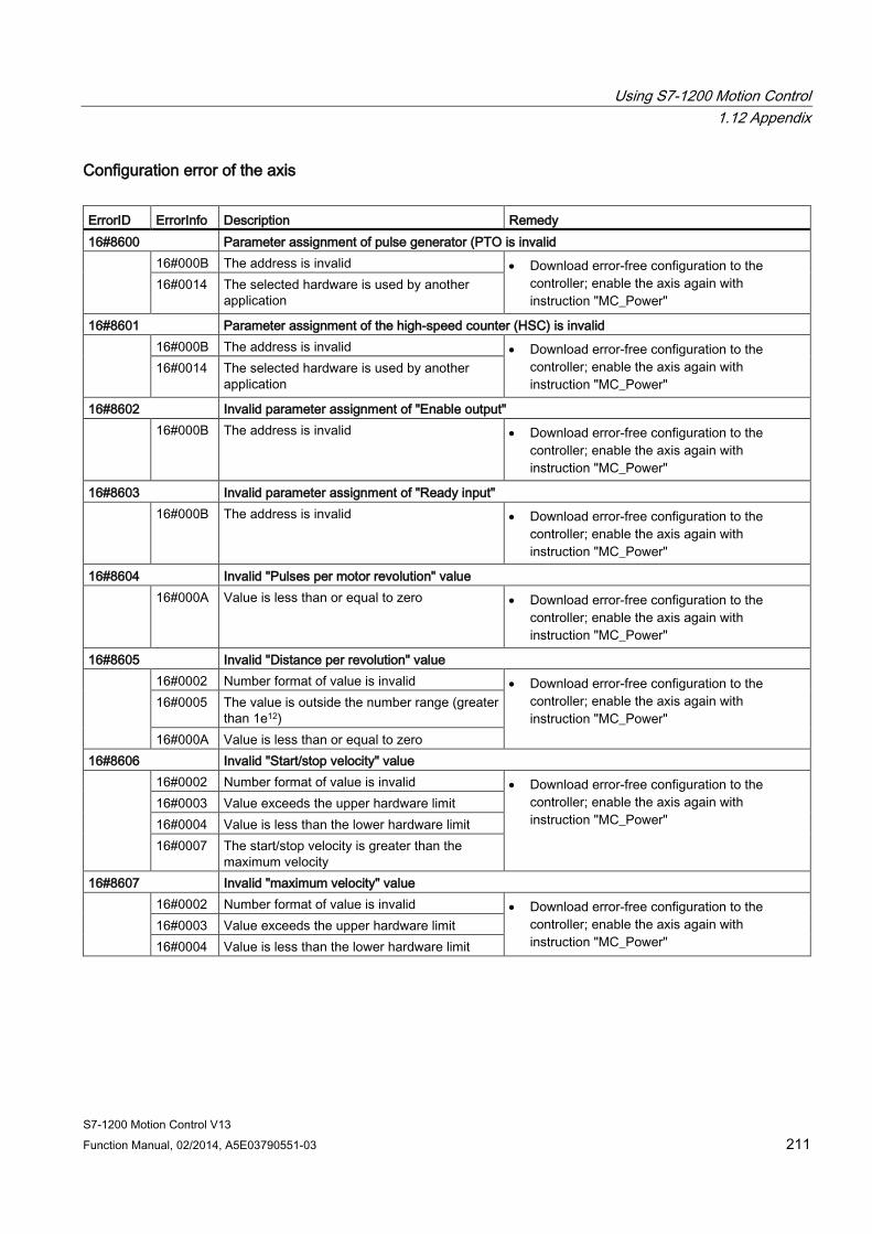
Using S7-1200 Motion Control 1.12 Appendix
S7-1200 Motion Control V13 Function Manual, 02/2014, A5E03790551-03 211
Configuration error of the axis ErrorID ErrorInfo Description Remedy 16#8600 Parameter assignment of pulse generator (PTO is invalid 16#000B The address is invalid • Download error-free configuration to the
controller; enable the axis again with instruction "MC_Power"
16#0014 The selected hardware is used by another application
16#8601 Parameter assignment of the high-speed counter (HSC) is invalid 16#000B The address is invalid • Download error-free configuration to the
controller; enable the axis again with instruction "MC_Power"
16#0014 The selected hardware is used by another application
16#8602 Invalid parameter assignment of "Enable output" 16#000B The address is invalid • Download error-free configuration to the
controller; enable the axis again with instruction "MC_Power"
16#8603 Invalid parameter assignment of "Ready input" 16#000B The address is invalid • Download error-free configuration to the
controller; enable the axis again with instruction "MC_Power"
16#8604 Invalid "Pulses per motor revolution" value 16#000A Value is less than or equal to zero • Download error-free configuration to the
controller; enable the axis again with instruction "MC_Power"
16#8605 Invalid "Distance per revolution" value 16#0002 Number format of value is invalid • Download error-free configuration to the
controller; enable the axis again with instruction "MC_Power"
16#0005 The value is outside the number range (greater than 1e12)
16#000A Value is less than or equal to zero 16#8606 Invalid "Start/stop velocity" value 16#0002 Number format of value is invalid • Download error-free configuration to the
controller; enable the axis again with instruction "MC_Power"
16#0003 Value exceeds the upper hardware limit 16#0004 Value is less than the lower hardware limit 16#0007 The start/stop velocity is greater than the
maximum velocity 16#8607 Invalid "maximum velocity" value 16#0002 Number format of value is invalid • Download error-free configuration to the
controller; enable the axis again with instruction "MC_Power"
16#0003 Value exceeds the upper hardware limit 16#0004 Value is less than the lower hardware limit
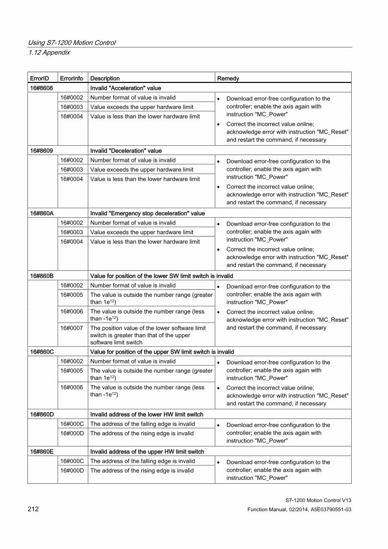
Using S7-1200 Motion Control 1.12 Appendix
S7-1200 Motion Control V13 212 Function Manual, 02/2014, A5E03790551-03
ErrorID ErrorInfo Description Remedy 16#8608 Invalid "Acceleration" value 16#0002 Number format of value is invalid • Download error-free configuration to the
controller; enable the axis again with instruction "MC_Power"
• Correct the incorrect value online; acknowledge error with instruction "MC_Reset" and restart the command, if necessary
16#0003 Value exceeds the upper hardware limit 16#0004 Value is less than the lower hardware limit
16#8609 Invalid "Deceleration" value 16#0002 Number format of value is invalid • Download error-free configuration to the
controller; enable the axis again with instruction "MC_Power"
• Correct the incorrect value online; acknowledge error with instruction "MC_Reset" and restart the command, if necessary
16#0003 Value exceeds the upper hardware limit 16#0004 Value is less than the lower hardware limit
16#860A Invalid "Emergency stop deceleration" value 16#0002 Number format of value is invalid • Download error-free configuration to the
controller; enable the axis again with instruction "MC_Power"
• Correct the incorrect value online; acknowledge error with instruction "MC_Reset" and restart the command, if necessary
16#0003 Value exceeds the upper hardware limit 16#0004 Value is less than the lower hardware limit
16#860B Value for position of the lower SW limit switch is invalid 16#0002 Number format of value is invalid • Download error-free configuration to the
controller; enable the axis again with instruction "MC_Power"
• Correct the incorrect value online; acknowledge error with instruction "MC_Reset" and restart the command, if necessary
16#0005 The value is outside the number range (greater than 1e12)
16#0006 The value is outside the number range (less than -1e12)
16#0007 The position value of the lower software limit switch is greater than that of the upper software limit switch
16#860C Value for position of the upper SW limit switch is invalid 16#0002 Number format of value is invalid • Download error-free configuration to the
controller; enable the axis again with instruction "MC_Power"
• Correct the incorrect value online; acknowledge error with instruction "MC_Reset" and restart the command, if necessary
16#0005 The value is outside the number range (greater than 1e12)
16#0006 The value is outside the number range (less than -1e12)
16#860D Invalid address of the lower HW limit switch 16#000C The address of the falling edge is invalid • Download error-free configuration to the
controller; enable the axis again with instruction "MC_Power"
16#000D The address of the rising edge is invalid
16#860E Invalid address of the upper HW limit switch 16#000C The address of the falling edge is invalid • Download error-free configuration to the
controller; enable the axis again with instruction "MC_Power"
16#000D The address of the rising edge is invalid
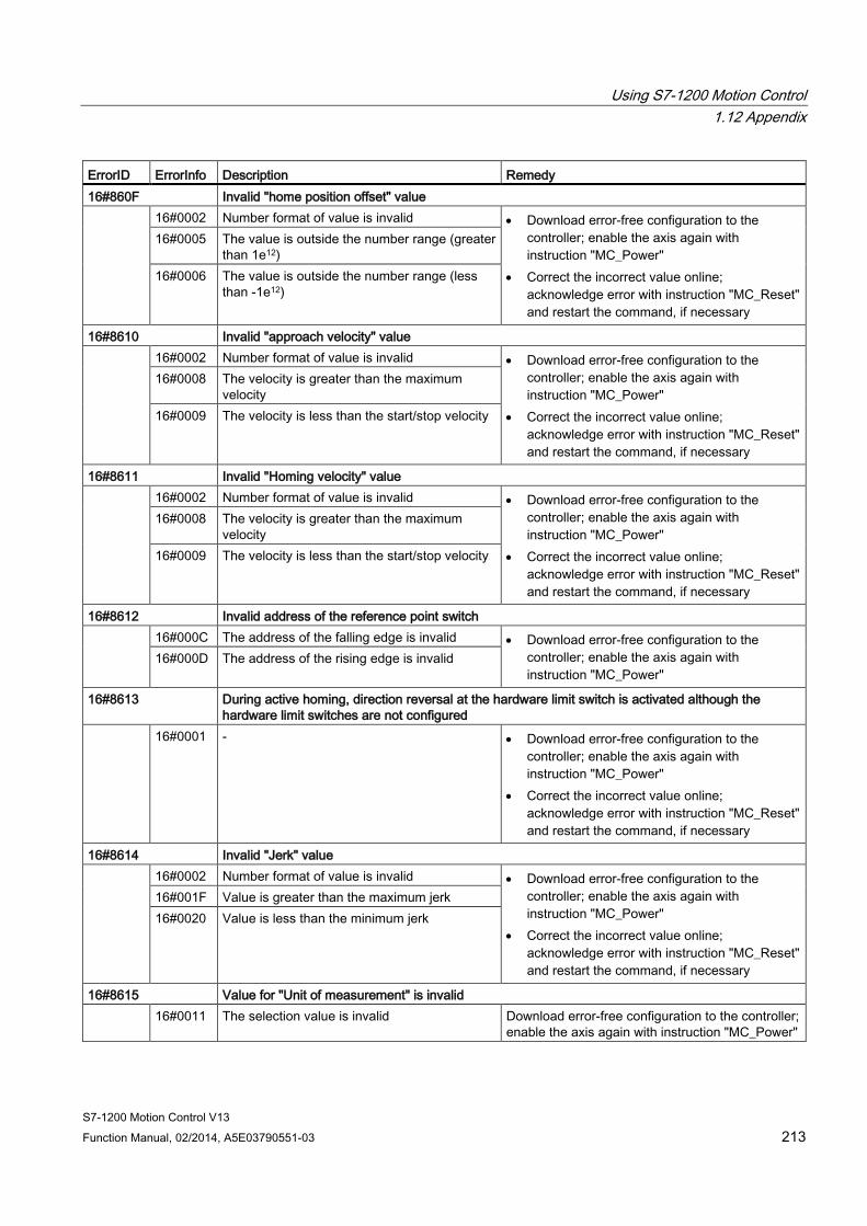
Using S7-1200 Motion Control 1.12 Appendix
S7-1200 Motion Control V13 Function Manual, 02/2014, A5E03790551-03 213
ErrorID ErrorInfo Description Remedy 16#860F Invalid "home position offset" value 16#0002 Number format of value is invalid • Download error-free configuration to the
controller; enable the axis again with instruction "MC_Power"
• Correct the incorrect value online; acknowledge error with instruction "MC_Reset" and restart the command, if necessary
16#0005 The value is outside the number range (greater than 1e12)
16#0006 The value is outside the number range (less than -1e12)
16#8610 Invalid "approach velocity" value 16#0002 Number format of value is invalid • Download error-free configuration to the
controller; enable the axis again with instruction "MC_Power"
• Correct the incorrect value online; acknowledge error with instruction "MC_Reset" and restart the command, if necessary
16#0008 The velocity is greater than the maximum velocity
16#0009 The velocity is less than the start/stop velocity
16#8611 Invalid "Homing velocity" value 16#0002 Number format of value is invalid • Download error-free configuration to the
controller; enable the axis again with instruction "MC_Power"
• Correct the incorrect value online; acknowledge error with instruction "MC_Reset" and restart the command, if necessary
16#0008 The velocity is greater than the maximum velocity
16#0009 The velocity is less than the start/stop velocity
16#8612 Invalid address of the reference point switch 16#000C The address of the falling edge is invalid • Download error-free configuration to the
controller; enable the axis again with instruction "MC_Power"
16#000D The address of the rising edge is invalid
16#8613 During active homing, direction reversal at the hardware limit switch is activated although the hardware limit switches are not configured
16#0001 - • Download error-free configuration to the controller; enable the axis again with instruction "MC_Power"
• Correct the incorrect value online; acknowledge error with instruction "MC_Reset" and restart the command, if necessary
16#8614 Invalid "Jerk" value 16#0002 Number format of value is invalid • Download error-free configuration to the
controller; enable the axis again with instruction "MC_Power"
• Correct the incorrect value online; acknowledge error with instruction "MC_Reset" and restart the command, if necessary
16#001F Value is greater than the maximum jerk 16#0020 Value is less than the minimum jerk
16#8615 Value for "Unit of measurement" is invalid 16#0011 The selection value is invalid Download error-free configuration to the controller;
enable the axis again with instruction "MC_Power"
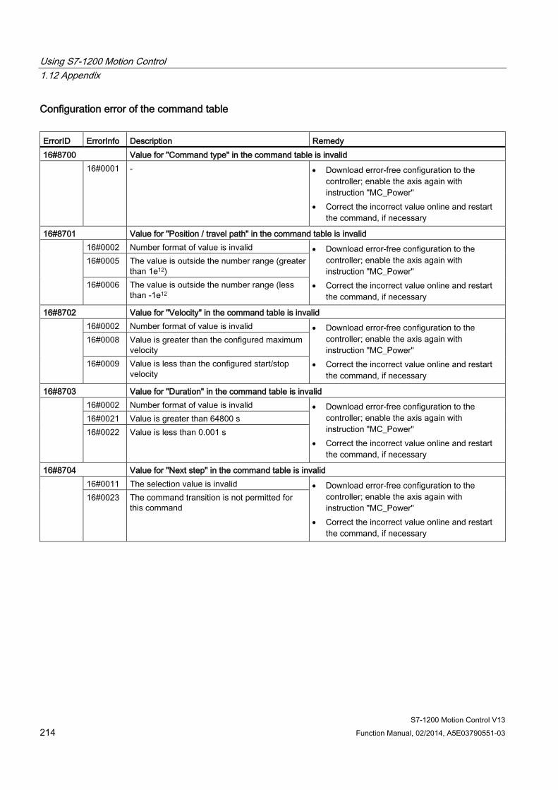
Using S7-1200 Motion Control 1.12 Appendix
S7-1200 Motion Control V13 214 Function Manual, 02/2014, A5E03790551-03
Configuration error of the command table ErrorID ErrorInfo Description Remedy 16#8700 Value for "Command type" in the command table is invalid 16#0001 - • Download error-free configuration to the
controller; enable the axis again with instruction "MC_Power"
• Correct the incorrect value online and restart the command, if necessary
16#8701 Value for "Position / travel path" in the command table is invalid 16#0002 Number format of value is invalid • Download error-free configuration to the
controller; enable the axis again with instruction "MC_Power"
• Correct the incorrect value online and restart the command, if necessary
16#0005 The value is outside the number range (greater than 1e12)
16#0006 The value is outside the number range (less than -1e12
16#8702 Value for "Velocity" in the command table is invalid 16#0002 Number format of value is invalid • Download error-free configuration to the
controller; enable the axis again with instruction "MC_Power"
• Correct the incorrect value online and restart the command, if necessary
16#0008 Value is greater than the configured maximum velocity
16#0009 Value is less than the configured start/stop velocity
16#8703 Value for "Duration" in the command table is invalid 16#0002 Number format of value is invalid • Download error-free configuration to the
controller; enable the axis again with instruction "MC_Power"
• Correct the incorrect value online and restart the command, if necessary
16#0021 Value is greater than 64800 s 16#0022 Value is less than 0.001 s
16#8704 Value for "Next step" in the command table is invalid 16#0011 The selection value is invalid • Download error-free configuration to the
controller; enable the axis again with instruction "MC_Power"
• Correct the incorrect value online and restart the command, if necessary
16#0023 The command transition is not permitted for this command
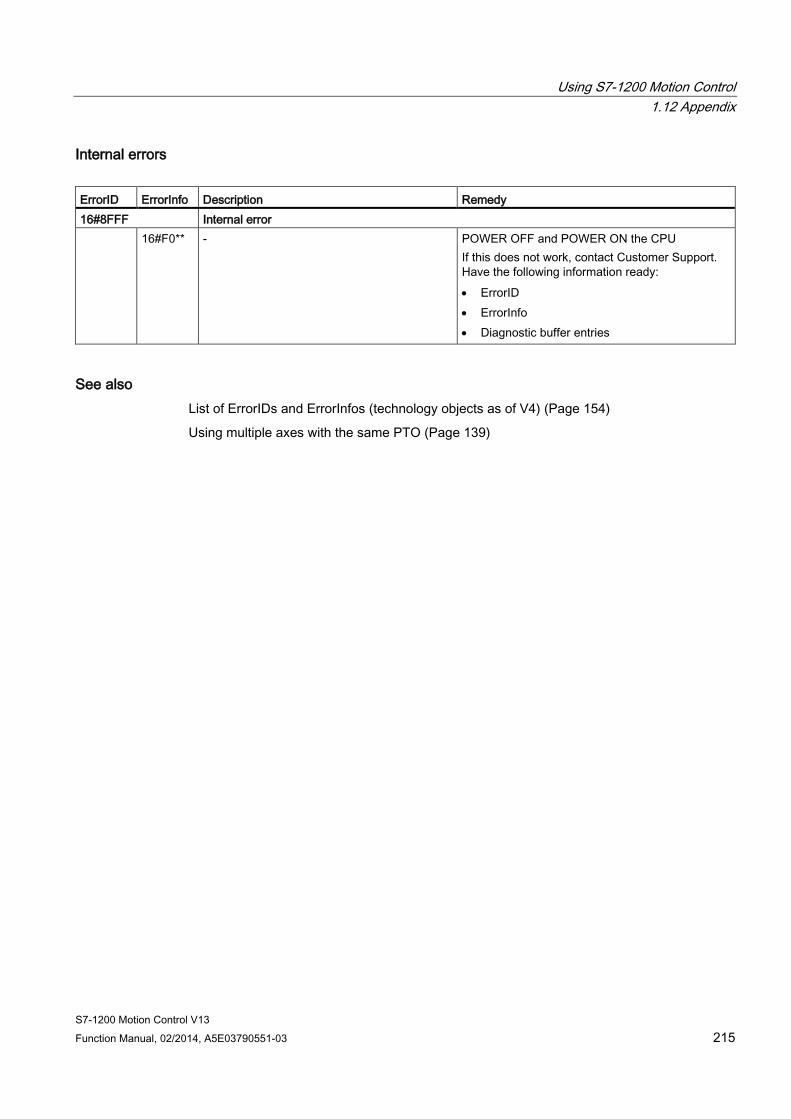
Using S7-1200 Motion Control 1.12 Appendix
S7-1200 Motion Control V13 Function Manual, 02/2014, A5E03790551-03 215
Internal errors ErrorID ErrorInfo Description Remedy 16#8FFF Internal error 16#F0** - POWER OFF and POWER ON the CPU
If this does not work, contact Customer Support. Have the following information ready: • ErrorID • ErrorInfo • Diagnostic buffer entries
See also List of ErrorIDs and ErrorInfos (technology objects as of V4) (Page 154)
Using multiple axes with the same PTO (Page 139)

Using S7-1200 Motion Control 1.12 Appendix
S7-1200 Motion Control V13 216 Function Manual, 02/2014, A5E03790551-03
List of ErrorIDs and ErrorInfos (technology objects V1) The following table lists all ErrorIDs and ErrorInfos that can be indicated in Motion Control instructions. In addition to the cause of the error, remedies for eliminating the error are also listed:
Operating error with axis stop ErrorID ErrorInfo Description Remedy 16#8000 Drive error, loss of "Drive ready" 16#0001 - Acknowledge error with instruction "MC_Reset";
provide drive signal; restart command, if necessary
16#8001 Lower SW limit switch has been tripped 16#000E The position of the lower SW limit switch was
reached with the currently configured deceleration
Acknowledge the error with instruction "MC_Reset"; use a motion command to move the axis in the positive direction out of the range of the SW limit switch 16#000F The position of the lower SW limit switch was
reached with the emergency stop deceleration 16#0010 The position of the lower SW limit switch was
exceeded with the emergency stop deceleration
16#8002 Upper SW limit switch has been tripped 16#000E The position of the upper SW limit switch was
reached with the currently configured deceleration
Acknowledge the error with instruction "MC_Reset"; use a motion command to move the axis in the negative direction out of the range of the SW limit switch 16#000F The position of the upper SW limit switch was
reached with the emergency stop deceleration 16#0010 The position of the upper SW limit switch was
exceeded with the emergency stop deceleration
16#8003 Lower HW limit switch was reached 16#000E The lower HW limit switch was reached. The
axis was stopped with the emergency stop deceleration. (During an active homing procedure, the reference point switch was not found)
Acknowledge the error for an enabled axis with instruction "MC_Reset"; use a motion command to move the axis in the positive direction out of the range of the HW limit switch.
16#8004 Upper HW limit switch was reached 16#000E The upper HW limit switch has been reached.
The axis was stopped with the emergency stop deceleration. (During an active homing procedure, the reference point switch was not found)
Acknowledge the error for an enabled axis with instruction "MC_Reset"; use a motion command to move the axis in the negative direction out of the range of the HW limit switch.
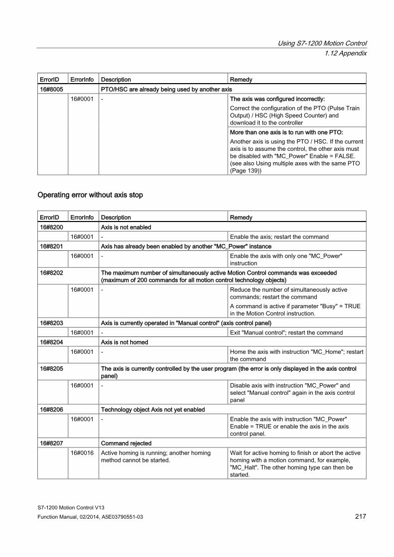
Using S7-1200 Motion Control 1.12 Appendix
S7-1200 Motion Control V13 Function Manual, 02/2014, A5E03790551-03 217
ErrorID ErrorInfo Description Remedy 16#8005 PTO/HSC are already being used by another axis 16#0001 - The axis was configured incorrectly:
Correct the configuration of the PTO (Pulse Train Output) / HSC (High Speed Counter) and download it to the controller More than one axis is to run with one PTO: Another axis is using the PTO / HSC. If the current axis is to assume the control, the other axis must be disabled with "MC_Power" Enable = FALSE. (see also Using multiple axes with the same PTO (Page 139))
Operating error without axis stop ErrorID ErrorInfo Description Remedy 16#8200 Axis is not enabled 16#0001 - Enable the axis; restart the command 16#8201 Axis has already been enabled by another "MC_Power" instance 16#0001 - Enable the axis with only one "MC_Power"
instruction 16#8202 The maximum number of simultaneously active Motion Control commands was exceeded
(maximum of 200 commands for all motion control technology objects) 16#0001 - Reduce the number of simultaneously active
commands; restart the command A command is active if parameter "Busy" = TRUE in the Motion Control instruction.
16#8203 Axis is currently operated in "Manual control" (axis control panel) 16#0001 - Exit "Manual control"; restart the command 16#8204 Axis is not homed 16#0001 - Home the axis with instruction "MC_Home"; restart
the command 16#8205 The axis is currently controlled by the user program (the error is only displayed in the axis control
panel) 16#0001 - Disable axis with instruction "MC_Power" and
select "Manual control" again in the axis control panel
16#8206 Technology object Axis not yet enabled 16#0001 - Enable the axis with instruction "MC_Power"
Enable = TRUE or enable the axis in the axis control panel.
16#8207 Command rejected 16#0016 Active homing is running; another homing
method cannot be started. Wait for active homing to finish or abort the active homing with a motion command, for example, "MC_Halt". The other homing type can then be started.
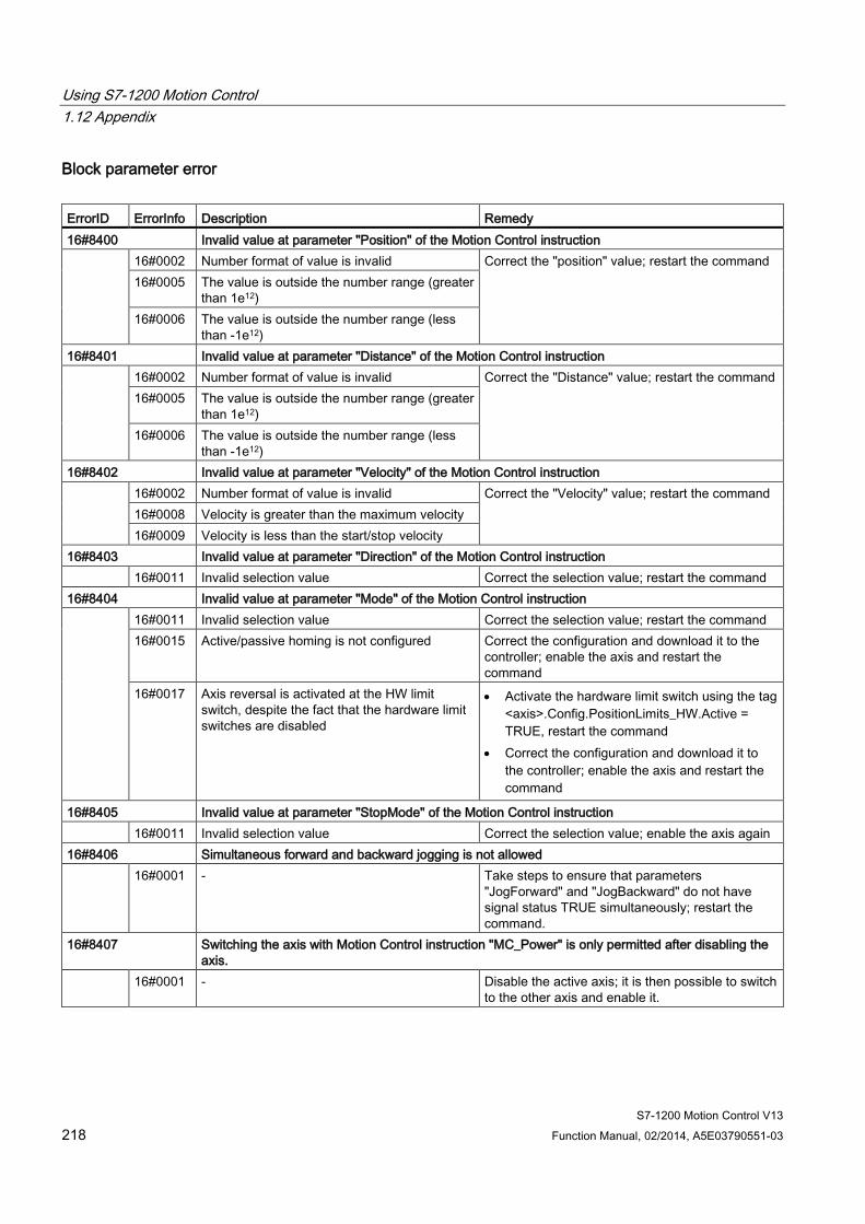
Using S7-1200 Motion Control 1.12 Appendix
S7-1200 Motion Control V13 218 Function Manual, 02/2014, A5E03790551-03
Block parameter error ErrorID ErrorInfo Description Remedy 16#8400 Invalid value at parameter "Position" of the Motion Control instruction 16#0002 Number format of value is invalid Correct the "position" value; restart the command
16#0005 The value is outside the number range (greater than 1e12)
16#0006 The value is outside the number range (less than -1e12)
16#8401 Invalid value at parameter "Distance" of the Motion Control instruction 16#0002 Number format of value is invalid Correct the "Distance" value; restart the command
16#0005 The value is outside the number range (greater than 1e12)
16#0006 The value is outside the number range (less than -1e12)
16#8402 Invalid value at parameter "Velocity" of the Motion Control instruction 16#0002 Number format of value is invalid Correct the "Velocity" value; restart the command
16#0008 Velocity is greater than the maximum velocity 16#0009 Velocity is less than the start/stop velocity
16#8403 Invalid value at parameter "Direction" of the Motion Control instruction 16#0011 Invalid selection value Correct the selection value; restart the command 16#8404 Invalid value at parameter "Mode" of the Motion Control instruction 16#0011 Invalid selection value Correct the selection value; restart the command
16#0015 Active/passive homing is not configured Correct the configuration and download it to the controller; enable the axis and restart the command
16#0017 Axis reversal is activated at the HW limit switch, despite the fact that the hardware limit switches are disabled
• Activate the hardware limit switch using the tag <axis>.Config.PositionLimits_HW.Active = TRUE, restart the command
• Correct the configuration and download it to the controller; enable the axis and restart the command
16#8405 Invalid value at parameter "StopMode" of the Motion Control instruction 16#0011 Invalid selection value Correct the selection value; enable the axis again 16#8406 Simultaneous forward and backward jogging is not allowed 16#0001 - Take steps to ensure that parameters
"JogForward" and "JogBackward" do not have signal status TRUE simultaneously; restart the command.
16#8407 Switching the axis with Motion Control instruction "MC_Power" is only permitted after disabling the axis.
16#0001 - Disable the active axis; it is then possible to switch to the other axis and enable it.
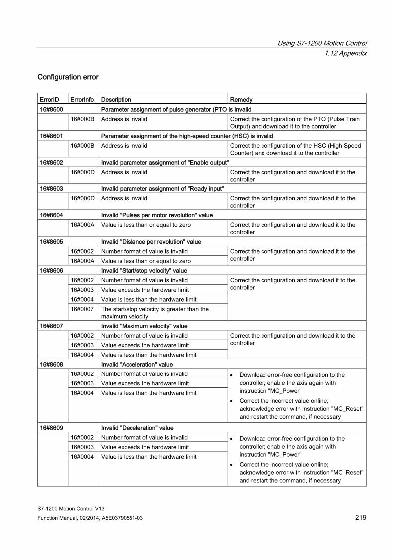
Using S7-1200 Motion Control 1.12 Appendix
S7-1200 Motion Control V13 Function Manual, 02/2014, A5E03790551-03 219
Configuration error ErrorID ErrorInfo Description Remedy 16#8600 Parameter assignment of pulse generator (PTO is invalid 16#000B Address is invalid Correct the configuration of the PTO (Pulse Train
Output) and download it to the controller 16#8601 Parameter assignment of the high-speed counter (HSC) is invalid 16#000B Address is invalid Correct the configuration of the HSC (High Speed
Counter) and download it to the controller 16#8602 Invalid parameter assignment of "Enable output" 16#000D Address is invalid Correct the configuration and download it to the
controller 16#8603 Invalid parameter assignment of "Ready input" 16#000D Address is invalid Correct the configuration and download it to the
controller 16#8604 Invalid "Pulses per motor revolution" value 16#000A Value is less than or equal to zero Correct the configuration and download it to the
controller 16#8605 Invalid "Distance per revolution" value 16#0002 Number format of value is invalid Correct the configuration and download it to the
controller 16#000A Value is less than or equal to zero 16#8606 Invalid "Start/stop velocity" value 16#0002 Number format of value is invalid Correct the configuration and download it to the
controller 16#0003 Value exceeds the hardware limit 16#0004 Value is less than the hardware limit 16#0007 The start/stop velocity is greater than the
maximum velocity 16#8607 Invalid "Maximum velocity" value 16#0002 Number format of value is invalid Correct the configuration and download it to the
controller 16#0003 Value exceeds the hardware limit 16#0004 Value is less than the hardware limit
16#8608 Invalid "Acceleration" value 16#0002 Number format of value is invalid • Download error-free configuration to the
controller; enable the axis again with instruction "MC_Power"
• Correct the incorrect value online; acknowledge error with instruction "MC_Reset" and restart the command, if necessary
16#0003 Value exceeds the hardware limit 16#0004 Value is less than the hardware limit
16#8609 Invalid "Deceleration" value 16#0002 Number format of value is invalid • Download error-free configuration to the
controller; enable the axis again with instruction "MC_Power"
• Correct the incorrect value online; acknowledge error with instruction "MC_Reset" and restart the command, if necessary
16#0003 Value exceeds the hardware limit 16#0004 Value is less than the hardware limit
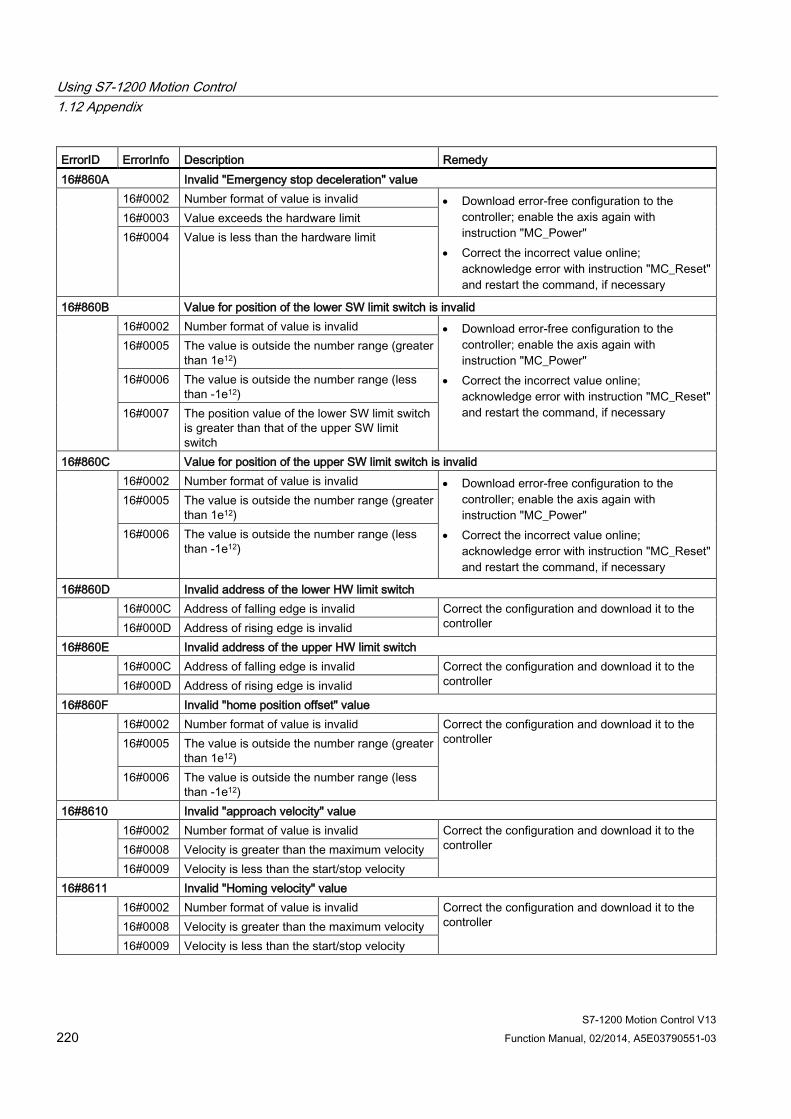
Using S7-1200 Motion Control 1.12 Appendix
S7-1200 Motion Control V13 220 Function Manual, 02/2014, A5E03790551-03
ErrorID ErrorInfo Description Remedy 16#860A Invalid "Emergency stop deceleration" value 16#0002 Number format of value is invalid • Download error-free configuration to the
controller; enable the axis again with instruction "MC_Power"
• Correct the incorrect value online; acknowledge error with instruction "MC_Reset" and restart the command, if necessary
16#0003 Value exceeds the hardware limit 16#0004 Value is less than the hardware limit
16#860B Value for position of the lower SW limit switch is invalid 16#0002 Number format of value is invalid • Download error-free configuration to the
controller; enable the axis again with instruction "MC_Power"
• Correct the incorrect value online; acknowledge error with instruction "MC_Reset" and restart the command, if necessary
16#0005 The value is outside the number range (greater than 1e12)
16#0006 The value is outside the number range (less than -1e12)
16#0007 The position value of the lower SW limit switch is greater than that of the upper SW limit switch
16#860C Value for position of the upper SW limit switch is invalid 16#0002 Number format of value is invalid • Download error-free configuration to the
controller; enable the axis again with instruction "MC_Power"
• Correct the incorrect value online; acknowledge error with instruction "MC_Reset" and restart the command, if necessary
16#0005 The value is outside the number range (greater than 1e12)
16#0006 The value is outside the number range (less than -1e12)
16#860D Invalid address of the lower HW limit switch 16#000C Address of falling edge is invalid Correct the configuration and download it to the
controller 16#000D Address of rising edge is invalid 16#860E Invalid address of the upper HW limit switch 16#000C Address of falling edge is invalid Correct the configuration and download it to the
controller 16#000D Address of rising edge is invalid 16#860F Invalid "home position offset" value 16#0002 Number format of value is invalid Correct the configuration and download it to the
controller 16#0005 The value is outside the number range (greater than 1e12)
16#0006 The value is outside the number range (less than -1e12)
16#8610 Invalid "approach velocity" value 16#0002 Number format of value is invalid Correct the configuration and download it to the
controller 16#0008 Velocity is greater than the maximum velocity 16#0009 Velocity is less than the start/stop velocity
16#8611 Invalid "Homing velocity" value 16#0002 Number format of value is invalid Correct the configuration and download it to the
controller 16#0008 Velocity is greater than the maximum velocity 16#0009 Velocity is less than the start/stop velocity
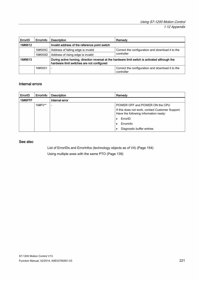
Using S7-1200 Motion Control 1.12 Appendix
S7-1200 Motion Control V13 Function Manual, 02/2014, A5E03790551-03 221
ErrorID ErrorInfo Description Remedy 16#8612 Invalid address of the reference point switch 16#000C Address of falling edge is invalid Correct the configuration and download it to the
controller 16#000D Address of rising edge is invalid 16#8613 During active homing, direction reversal at the hardware limit switch is activated although the
hardware limit switches are not configured 16#0001 - Correct the configuration and download it to the
controller
Internal errors ErrorID ErrorInfo Description Remedy 16#8FFF Internal error 16#F0** - POWER OFF and POWER ON the CPU
If this does not work, contact Customer Support. Have the following information ready: • ErrorID • ErrorInfo • Diagnostic buffer entries
See also List of ErrorIDs and ErrorInfos (technology objects as of V4) (Page 154)
Using multiple axes with the same PTO (Page 139)
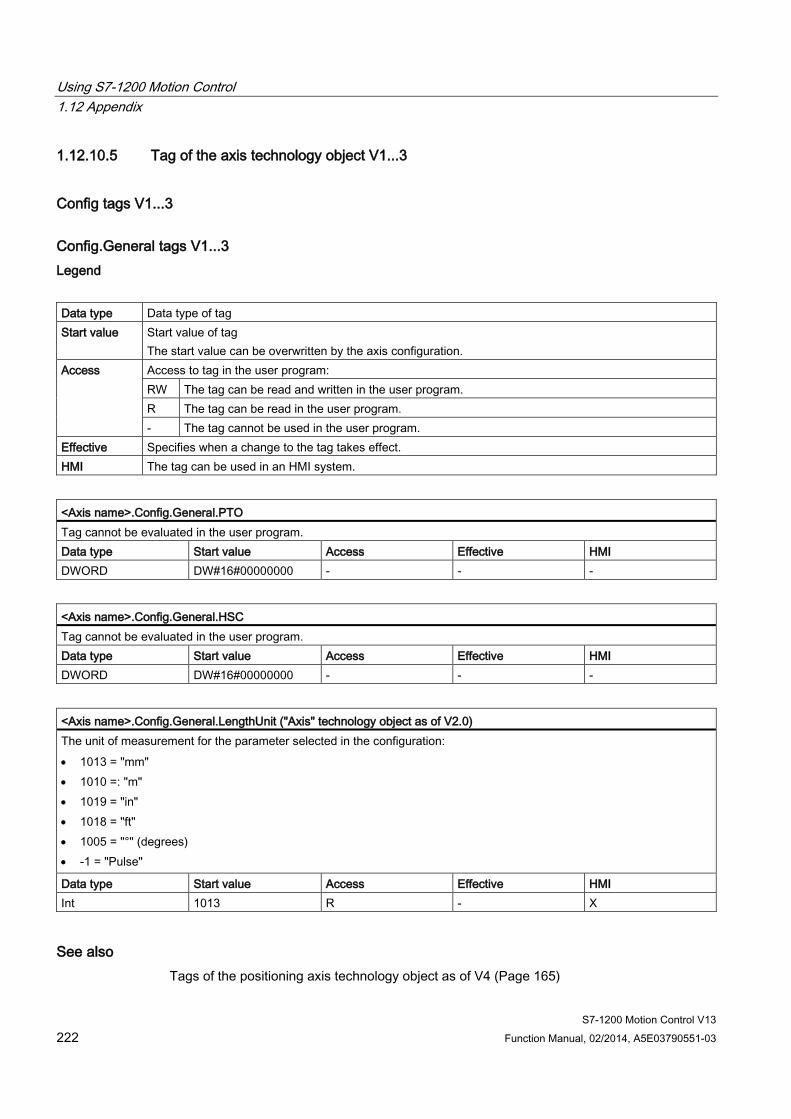
Using S7-1200 Motion Control 1.12 Appendix
S7-1200 Motion Control V13 222 Function Manual, 02/2014, A5E03790551-03
1.12.10.5 Tag of the axis technology object V1...3
Config tags V1...3
Config.General tags V1...3 Legend
Data type Data type of tag Start value Start value of tag
The start value can be overwritten by the axis configuration. Access Access to tag in the user program:
RW The tag can be read and written in the user program. R The tag can be read in the user program. - The tag cannot be used in the user program.
Effective Specifies when a change to the tag takes effect. HMI The tag can be used in an HMI system.
<Axis name>.Config.General.PTO Tag cannot be evaluated in the user program. Data type Start value Access Effective HMI DWORD DW#16#00000000 - - -
<Axis name>.Config.General.HSC Tag cannot be evaluated in the user program. Data type Start value Access Effective HMI DWORD DW#16#00000000 - - -
<Axis name>.Config.General.LengthUnit ("Axis" technology object as of V2.0) The unit of measurement for the parameter selected in the configuration: • 1013 = "mm" • 1010 =: "m" • 1019 = "in" • 1018 = "ft" • 1005 = "°" (degrees) • -1 = "Pulse"
Data type Start value Access Effective HMI Int 1013 R - X
See also Tags of the positioning axis technology object as of V4 (Page 165)
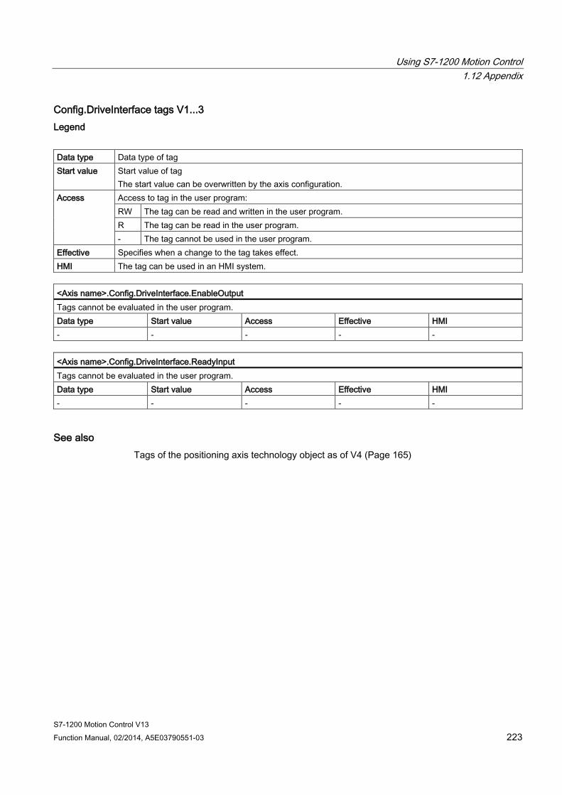
Using S7-1200 Motion Control 1.12 Appendix
S7-1200 Motion Control V13 Function Manual, 02/2014, A5E03790551-03 223
Config.DriveInterface tags V1...3 Legend
Data type Data type of tag Start value Start value of tag
The start value can be overwritten by the axis configuration. Access Access to tag in the user program:
RW The tag can be read and written in the user program. R The tag can be read in the user program. - The tag cannot be used in the user program.
Effective Specifies when a change to the tag takes effect. HMI The tag can be used in an HMI system.
<Axis name>.Config.DriveInterface.EnableOutput Tags cannot be evaluated in the user program. Data type Start value Access Effective HMI - - - - -
<Axis name>.Config.DriveInterface.ReadyInput Tags cannot be evaluated in the user program. Data type Start value Access Effective HMI - - - - -
See also Tags of the positioning axis technology object as of V4 (Page 165)
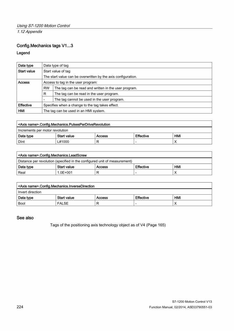
Using S7-1200 Motion Control 1.12 Appendix
S7-1200 Motion Control V13 224 Function Manual, 02/2014, A5E03790551-03
Config.Mechanics tags V1...3 Legend
Data type Data type of tag Start value Start value of tag
The start value can be overwritten by the axis configuration. Access Access to tag in the user program:
RW The tag can be read and written in the user program. R The tag can be read in the user program. - The tag cannot be used in the user program.
Effective Specifies when a change to the tag takes effect. HMI The tag can be used in an HMI system.
<Axis name>.Config.Mechanics.PulsesPerDriveRevolution Increments per motor revolution Data type Start value Access Effective HMI DInt L#1000 R - X
<Axis name>.Config.Mechanics.LeadScrew Distance per revolution (specified in the configured unit of measurement) Data type Start value Access Effective HMI Real 1.0E+001 R - X
<Axis name>.Config.Mechanics.InverseDirection Invert direction Data type Start value Access Effective HMI Bool FALSE R - X
See also Tags of the positioning axis technology object as of V4 (Page 165)

Using S7-1200 Motion Control 1.12 Appendix
S7-1200 Motion Control V13 Function Manual, 02/2014, A5E03790551-03 225
Config.DynamicLimits tags V1...3 Legend
Data type Data type of tag Start value Start value of tag
The start value can be overwritten by the axis configuration. Access Access to tag in the user program:
RW The tag can be read and written in the user program. R The tag can be read in the user program. - The tag cannot be used in the user program.
Effective Specifies when a change to the tag takes effect. HMI The tag can be used in an HMI system.
<Axis name>.Config.DynamicLimits.MinVelocity Start/stop velocity of axis (specified in the configured unit of measurement) Data type Start value Access Effective HMI Real 1.0E+001 R - X
<Axis name>.Config.DynamicLimits.MaxVelocity Maximum velocity of axis (specified in the configured unit of measurement) Data type Start value Access Effective HMI Real 2.5E+002 R - X
See also Tags of the positioning axis technology object as of V4 (Page 165)
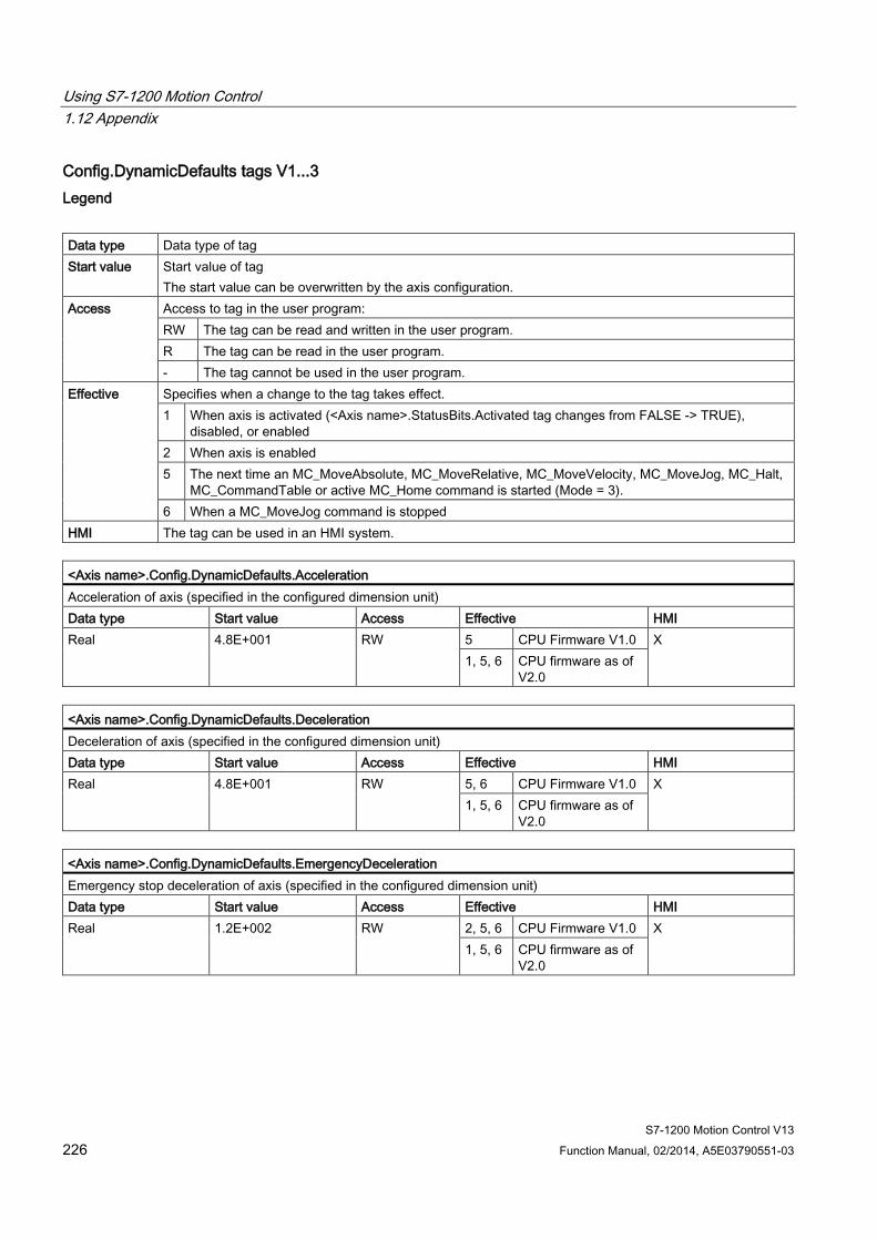
Using S7-1200 Motion Control 1.12 Appendix
S7-1200 Motion Control V13 226 Function Manual, 02/2014, A5E03790551-03
Config.DynamicDefaults tags V1...3 Legend
Data type Data type of tag Start value Start value of tag
The start value can be overwritten by the axis configuration. Access Access to tag in the user program:
RW The tag can be read and written in the user program. R The tag can be read in the user program. - The tag cannot be used in the user program.
Effective Specifies when a change to the tag takes effect. 1 When axis is activated (<Axis name>.StatusBits.Activated tag changes from FALSE -> TRUE),
disabled, or enabled 2 When axis is enabled 5 The next time an MC_MoveAbsolute, MC_MoveRelative, MC_MoveVelocity, MC_MoveJog, MC_Halt,
MC_CommandTable or active MC_Home command is started (Mode = 3). 6 When a MC_MoveJog command is stopped
HMI The tag can be used in an HMI system.
<Axis name>.Config.DynamicDefaults.Acceleration Acceleration of axis (specified in the configured dimension unit) Data type Start value Access Effective HMI Real 4.8E+001 RW 5 CPU Firmware V1.0 X
1, 5, 6 CPU firmware as of V2.0
<Axis name>.Config.DynamicDefaults.Deceleration Deceleration of axis (specified in the configured dimension unit) Data type Start value Access Effective HMI Real 4.8E+001 RW 5, 6 CPU Firmware V1.0 X
1, 5, 6 CPU firmware as of V2.0
<Axis name>.Config.DynamicDefaults.EmergencyDeceleration Emergency stop deceleration of axis (specified in the configured dimension unit) Data type Start value Access Effective HMI Real 1.2E+002 RW 2, 5, 6 CPU Firmware V1.0 X
1, 5, 6 CPU firmware as of V2.0
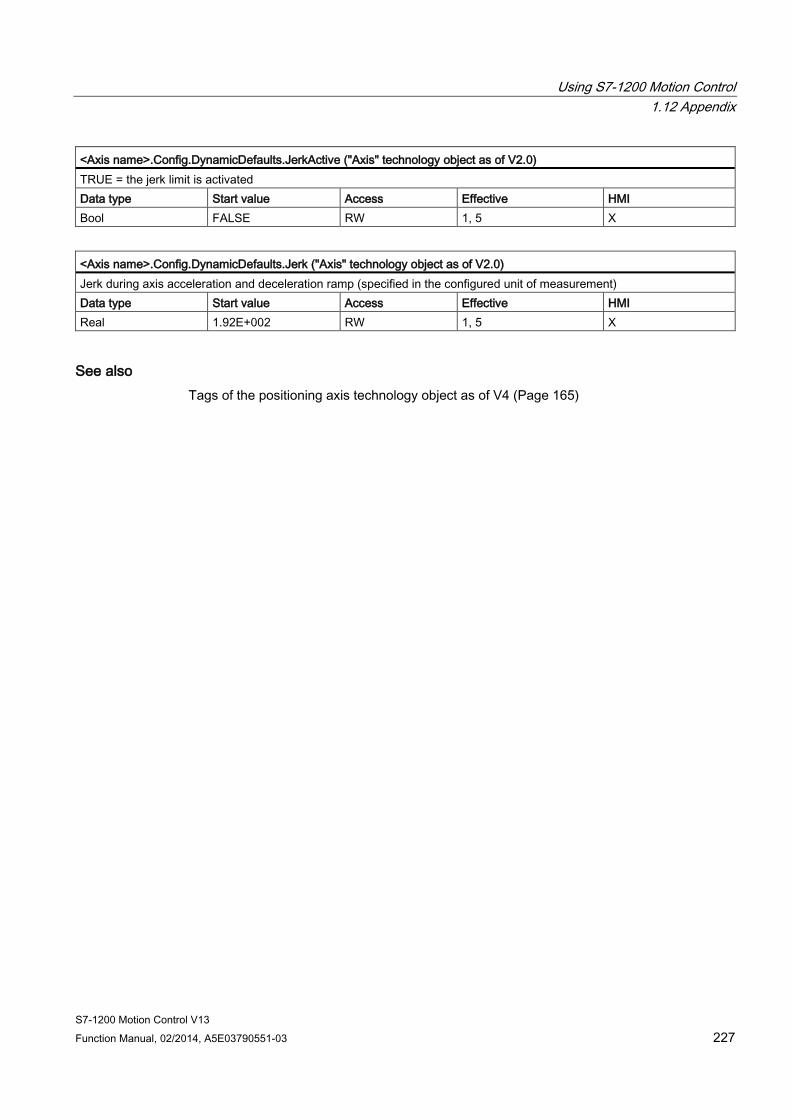
Using S7-1200 Motion Control 1.12 Appendix
S7-1200 Motion Control V13 Function Manual, 02/2014, A5E03790551-03 227
<Axis name>.Config.DynamicDefaults.JerkActive ("Axis" technology object as of V2.0) TRUE = the jerk limit is activated Data type Start value Access Effective HMI Bool FALSE RW 1, 5 X
<Axis name>.Config.DynamicDefaults.Jerk ("Axis" technology object as of V2.0) Jerk during axis acceleration and deceleration ramp (specified in the configured unit of measurement) Data type Start value Access Effective HMI Real 1.92E+002 RW 1, 5 X
See also Tags of the positioning axis technology object as of V4 (Page 165)
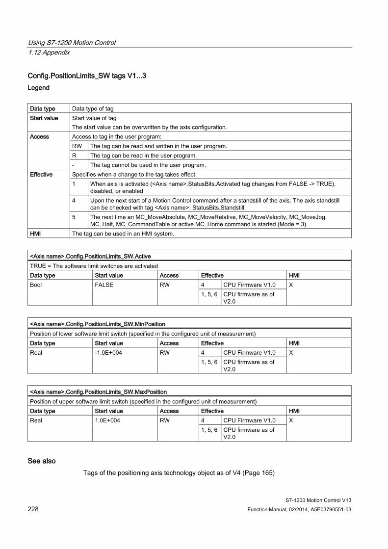
Using S7-1200 Motion Control 1.12 Appendix
S7-1200 Motion Control V13 228 Function Manual, 02/2014, A5E03790551-03
Config.PositionLimits_SW tags V1...3 Legend
Data type Data type of tag Start value Start value of tag
The start value can be overwritten by the axis configuration. Access Access to tag in the user program:
RW The tag can be read and written in the user program. R The tag can be read in the user program. - The tag cannot be used in the user program.
Effective Specifies when a change to the tag takes effect. 1 When axis is activated (<Axis name>.StatusBits.Activated tag changes from FALSE -> TRUE),
disabled, or enabled 4 Upon the next start of a Motion Control command after a standstill of the axis. The axis standstill
can be checked with tag <Axis name>. StatusBits.Standstill. 5 The next time an MC_MoveAbsolute, MC_MoveRelative, MC_MoveVelocity, MC_MoveJog,
MC_Halt, MC_CommandTable or active MC_Home command is started (Mode = 3). HMI The tag can be used in an HMI system.
<Axis name>.Config.PositionLimits_SW.Active TRUE = The software limit switches are activated Data type Start value Access Effective HMI Bool FALSE RW 4 CPU Firmware V1.0 X
1, 5, 6 CPU firmware as of V2.0
<Axis name>.Config.PositionLimits_SW.MinPosition Position of lower software limit switch (specified in the configured unit of measurement) Data type Start value Access Effective HMI Real -1.0E+004 RW 4 CPU Firmware V1.0 X
1, 5, 6 CPU firmware as of V2.0
<Axis name>.Config.PositionLimits_SW.MaxPosition Position of upper software limit switch (specified in the configured unit of measurement) Data type Start value Access Effective HMI Real 1.0E+004 RW 4 CPU Firmware V1.0 X
1, 5, 6 CPU firmware as of V2.0
See also Tags of the positioning axis technology object as of V4 (Page 165)
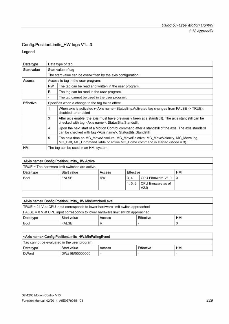
Using S7-1200 Motion Control 1.12 Appendix
S7-1200 Motion Control V13 Function Manual, 02/2014, A5E03790551-03 229
Config.PositionLimits_HW tags V1...3 Legend
Data type Data type of tag Start value Start value of tag
The start value can be overwritten by the axis configuration. Access Access to tag in the user program:
RW The tag can be read and written in the user program. R The tag can be read in the user program. - The tag cannot be used in the user program.
Effective Specifies when a change to the tag takes effect. 1 When axis is activated (<Axis name>.StatusBits.Activated tag changes from FALSE -> TRUE),
disabled, or enabled 3 After axis enable (the axis must have previously been at a standstill). The axis standstill can be
checked with tag <Axis name>. StatusBits.Standstill. 4 Upon the next start of a Motion Control command after a standstill of the axis. The axis standstill
can be checked with tag <Axis name>. StatusBits.Standstill. 5 The next time an MC_MoveAbsolute, MC_MoveRelative, MC_MoveVelocity, MC_MoveJog,
MC_Halt, MC_CommandTable or active MC_Home command is started (Mode = 3). HMI The tag can be used in an HMI system.
<Axis name>.Config.PositionLimits_HW.Active TRUE = The hardware limit switches are active. Data type Start value Access Effective HMI Bool FALSE RW 3, 4 CPU Firmware V1.0 X
1, 5, 6 CPU firmware as of V2.0
<Axis name>.Config.PositionLimits_HW.MinSwitchedLevel TRUE = 24 V at CPU input corresponds to lower hardware limit switch approached FALSE = 0 V at CPU input corresponds to lower hardware limit switch approached Data type Start value Access Effective HMI Bool FALSE R - X
<Axis name>.Config.PositionLimits_HW.MinFallingEvent Tag cannot be evaluated in the user program. Data type Start value Access Effective HMI DWord DW#16#00000000 - - -
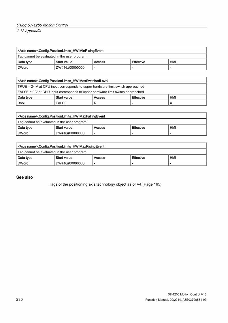
Using S7-1200 Motion Control 1.12 Appendix
S7-1200 Motion Control V13 230 Function Manual, 02/2014, A5E03790551-03
<Axis name>.Config.PositionLimits_HW.MinRisingEvent Tag cannot be evaluated in the user program. Data type Start value Access Effective HMI DWord DW#16#00000000 - - -
<Axis name>.Config.PositionLimits_HW.MaxSwitchedLevel TRUE = 24 V at CPU input corresponds to upper hardware limit switch approached FALSE = 0 V at CPU input corresponds to upper hardware limit switch approached Data type Start value Access Effective HMI Bool FALSE R - X
<Axis name>.Config.PositionLimits_HW.MaxFallingEvent Tag cannot be evaluated in the user program. Data type Start value Access Effective HMI DWord DW#16#00000000 - - -
<Axis name>.Config.PositionLimits_HW.MaxRisingEvent Tag cannot be evaluated in the user program. Data type Start value Access Effective HMI DWord DW#16#00000000 - - -
See also Tags of the positioning axis technology object as of V4 (Page 165)

Using S7-1200 Motion Control 1.12 Appendix
S7-1200 Motion Control V13 Function Manual, 02/2014, A5E03790551-03 231
Config.Homing tags V1...3 Legend
Data type Data type of tag Start value Start value of tag
The start value can be overwritten by the axis configuration. Access Access to tag in the user program:
RW The tag can be read and written in the user program. R The tag can be read in the user program. - The tag cannot be used in the user program.
Effective Specifies when a change to the tag takes effect. 1 When axis is activated (<Axis name>.StatusBits.Activated tag changes from FALSE -> TRUE),
disabled, or enabled 7 When a passive homing command is started 8 When an active homing command is started
HMI The tag can be used in an HMI system.
<Axis name>.Config.Homing.AutoReversal TRUE = Direction reversal at hardware limit switch enabled (active homing) FALSE = Direction reversal at hardware limit switch disabled (active homing) Data type Start value Access Effective HMI Bool TRUE R - Technology object
"Axis" V1.0 X
RW 1, 8 Technology object "Axis" V2.0
<Axis name>.Config.Homing.Direction TRUE = Positive approach direction to search for reference point switch and positive homing direction (active homing) FALSE = Negative approach direction to search for reference point switch and positive homing direction (active homing) Data type Start value Access Effective HMI Bool TRUE R - Technology object
"Axis" V1.0 X
RW 1, 8 Technology object "Axis" V2.0
<Axis name>.Config.Homing.SideActiveHoming ("Axis" technology object as of V2.0) TRUE = Homing on high end of the reference point switch (active homing) TRUE = Homing on lower end of the reference point switch (active homing) Data type Start value Access Effective HMI Bool TRUE RW 1, 8 X
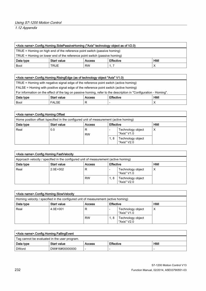
Using S7-1200 Motion Control 1.12 Appendix
S7-1200 Motion Control V13 232 Function Manual, 02/2014, A5E03790551-03
<Axis name>.Config.Homing.SidePassiveHoming ("Axis" technology object as of V2.0) TRUE = Homing on high end of the reference point switch (passive homing) TRUE = Homing on lower end of the reference point switch (passive homing) Data type Start value Access Effective HMI Bool TRUE RW 1, 7 X
<Axis name>.Config.Homing.RisingEdge (as of technology object "Axis" V1.0) TRUE = Homing with negative signal edge of the reference point switch (active homing) FALSE = Homing with positive signal edge of the reference point switch (active homing) For information on the effect of the tag on passive homing, refer to the description in "Configuration - Homing". Data type Start value Access Effective HMI Bool FALSE R - X
<Axis name>.Config.Homing.Offset Home position offset /specified in the configured unit of measurement (active homing) Data type Start value Access Effective HMI Real 0.0 R
RW - Technology object
"Axis" V1.0 X
1, 8 Technology object "Axis" V2.0
<Axis name>.Config.Homing.FastVelocity Approach velocity / specified in the configured unit of measurement (active homing) Data type Start value Access Effective HMI Real 2.0E+002 R - Technology object
"Axis" V1.0 X
RW 1, 8 Technology object "Axis" V2.0
<Axis name>.Config.Homing.SlowVelocity Homing velocity / specified in the configured unit of measurement (active homing) Data type Start value Access Effective HMI Real 4.0E+001 R - Technology object
"Axis" V1.0 X
RW 1, 8 Technology object "Axis" V2.0
<Axis name>.Config.Homing.FallingEvent Tag cannot be evaluated in the user program. Data type Start value Access Effective HMI DWord DW#16#00000000 - - -
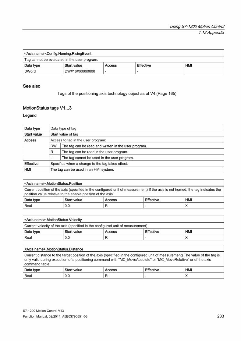
Using S7-1200 Motion Control 1.12 Appendix
S7-1200 Motion Control V13 Function Manual, 02/2014, A5E03790551-03 233
<Axis name>.Config.Homing.RisingEvent Tag cannot be evaluated in the user program. Data type Start value Access Effective HMI DWord DW#16#00000000 - -
See also Tags of the positioning axis technology object as of V4 (Page 165)
MotionStatus tags V1...3 Legend
Data type Data type of tag Start value Start value of tag Access Access to tag in the user program:
RW The tag can be read and written in the user program. R The tag can be read in the user program. - The tag cannot be used in the user program.
Effective Specifies when a change to the tag takes effect. HMI The tag can be used in an HMI system.
<Axis name>.MotionStatus.Position Current position of the axis (specified in the configured unit of measurement) If the axis is not homed, the tag indicates the position value relative to the enable position of the axis. Data type Start value Access Effective HMI Real 0.0 R - X
<Axis name>.MotionStatus.Velocity Current velocity of the axis (specified in the configured unit of measurement) Data type Start value Access Effective HMI Real 0.0 R - X
<Axis name>.MotionStatus.Distance Current distance to the target position of the axis (specified in the configured unit of measurement) The value of the tag is only valid during execution of a positioning command with "MC_MoveAbsolute" or "MC_MoveRelative" or of the axis command table. Data type Start value Access Effective HMI Real 0.0 R - X
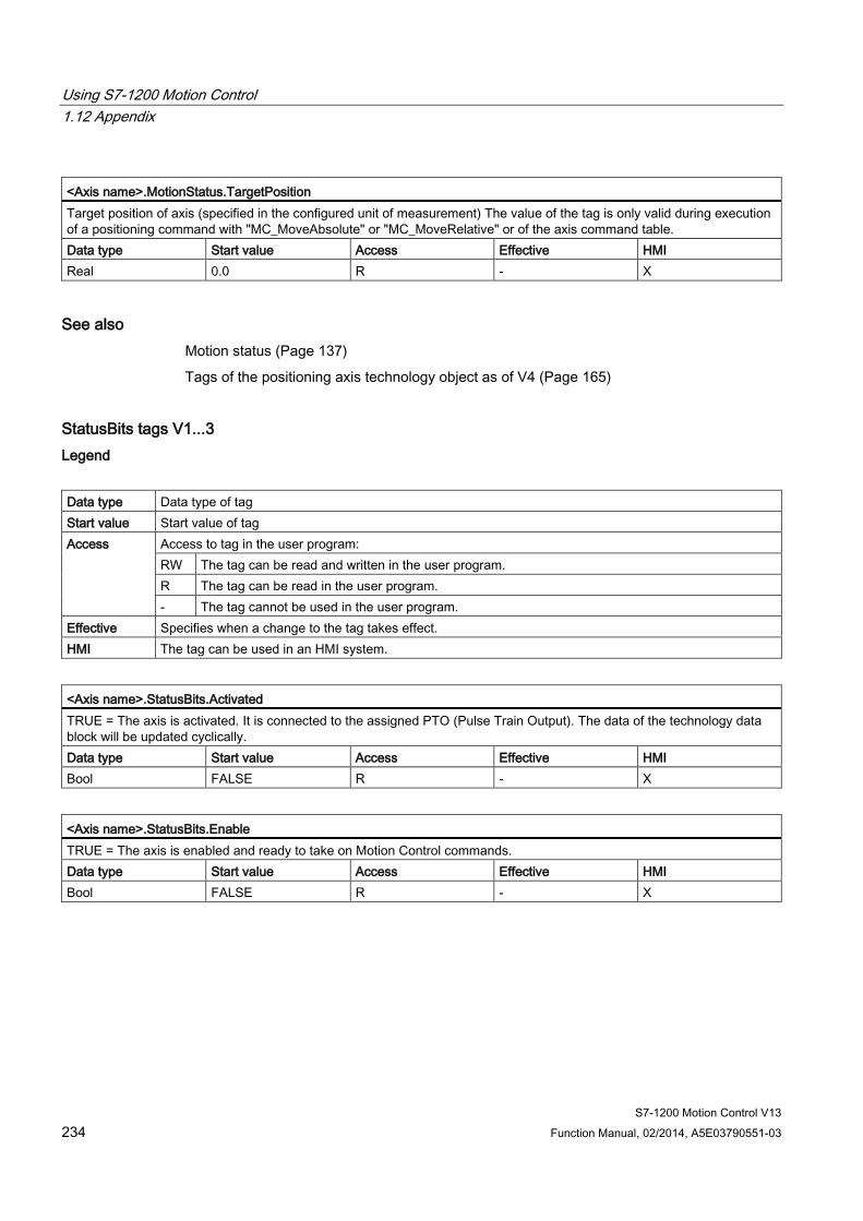
Using S7-1200 Motion Control 1.12 Appendix
S7-1200 Motion Control V13 234 Function Manual, 02/2014, A5E03790551-03
<Axis name>.MotionStatus.TargetPosition Target position of axis (specified in the configured unit of measurement) The value of the tag is only valid during execution of a positioning command with "MC_MoveAbsolute" or "MC_MoveRelative" or of the axis command table. Data type Start value Access Effective HMI Real 0.0 R - X
See also Motion status (Page 137)
Tags of the positioning axis technology object as of V4 (Page 165)
StatusBits tags V1...3 Legend
Data type Data type of tag Start value Start value of tag Access Access to tag in the user program:
RW The tag can be read and written in the user program. R The tag can be read in the user program. - The tag cannot be used in the user program.
Effective Specifies when a change to the tag takes effect. HMI The tag can be used in an HMI system.
<Axis name>.StatusBits.Activated TRUE = The axis is activated. It is connected to the assigned PTO (Pulse Train Output). The data of the technology data block will be updated cyclically. Data type Start value Access Effective HMI Bool FALSE R - X
<Axis name>.StatusBits.Enable TRUE = The axis is enabled and ready to take on Motion Control commands. Data type Start value Access Effective HMI Bool FALSE R - X
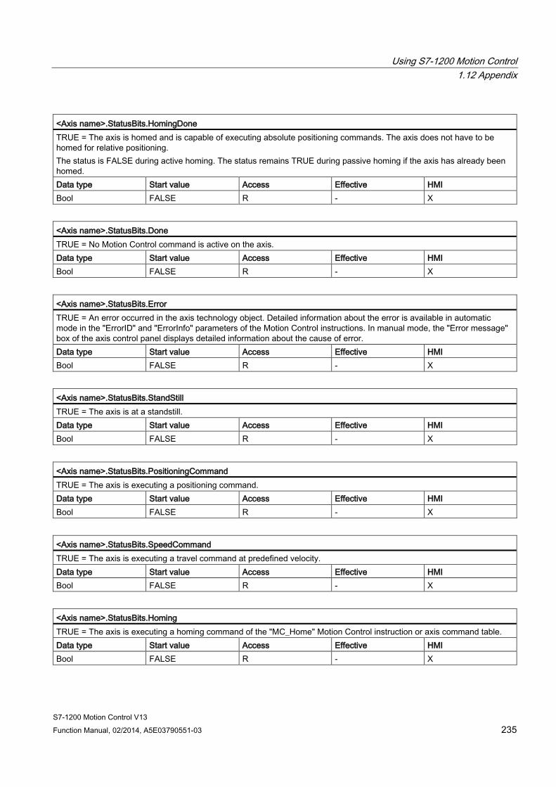
Using S7-1200 Motion Control 1.12 Appendix
S7-1200 Motion Control V13 Function Manual, 02/2014, A5E03790551-03 235
<Axis name>.StatusBits.HomingDone TRUE = The axis is homed and is capable of executing absolute positioning commands. The axis does not have to be homed for relative positioning. The status is FALSE during active homing. The status remains TRUE during passive homing if the axis has already been homed. Data type Start value Access Effective HMI Bool FALSE R - X
<Axis name>.StatusBits.Done TRUE = No Motion Control command is active on the axis. Data type Start value Access Effective HMI Bool FALSE R - X
<Axis name>.StatusBits.Error TRUE = An error occurred in the axis technology object. Detailed information about the error is available in automatic mode in the "ErrorID" and "ErrorInfo" parameters of the Motion Control instructions. In manual mode, the "Error message" box of the axis control panel displays detailed information about the cause of error. Data type Start value Access Effective HMI Bool FALSE R - X
<Axis name>.StatusBits.StandStill TRUE = The axis is at a standstill. Data type Start value Access Effective HMI Bool FALSE R - X
<Axis name>.StatusBits.PositioningCommand TRUE = The axis is executing a positioning command. Data type Start value Access Effective HMI Bool FALSE R - X
<Axis name>.StatusBits.SpeedCommand TRUE = The axis is executing a travel command at predefined velocity. Data type Start value Access Effective HMI Bool FALSE R - X
<Axis name>.StatusBits.Homing TRUE = The axis is executing a homing command of the "MC_Home" Motion Control instruction or axis command table. Data type Start value Access Effective HMI Bool FALSE R - X
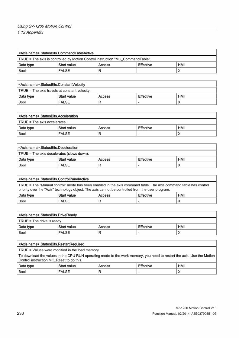
Using S7-1200 Motion Control 1.12 Appendix
S7-1200 Motion Control V13 236 Function Manual, 02/2014, A5E03790551-03
<Axis name>.StatusBits.CommandTableActive TRUE = The axis is controlled by Motion Control instruction "MC_CommandTable". Data type Start value Access Effective HMI Bool FALSE R - X
<Axis name>.StatusBits.ConstantVelocity TRUE = The axis travels at constant velocity. Data type Start value Access Effective HMI Bool FALSE R - X
<Axis name>.StatusBits.Acceleration TRUE = The axis accelerates. Data type Start value Access Effective HMI Bool FALSE R - X
<Axis name>.StatusBits.Deceleration TRUE = The axis decelerates (slows down). Data type Start value Access Effective HMI Bool FALSE R - X
<Axis name>.StatusBits.ControlPanelActive TRUE = The "Manual control" mode has been enabled in the axis command table. The axis command table has control priority over the "Axis" technology object. The axis cannot be controlled from the user program. Data type Start value Access Effective HMI Bool FALSE R - X
<Axis name>.StatusBits.DriveReady TRUE = The drive is ready. Data type Start value Access Effective HMI Bool FALSE R - X
<Axis name>.StatusBits.RestartRequired TRUE = Values were modified in the load memory. To download the values in the CPU RUN operating mode to the work memory, you need to restart the axis. Use the Motion Control instruction MC_Reset to do this. Data type Start value Access Effective HMI Bool FALSE R - X
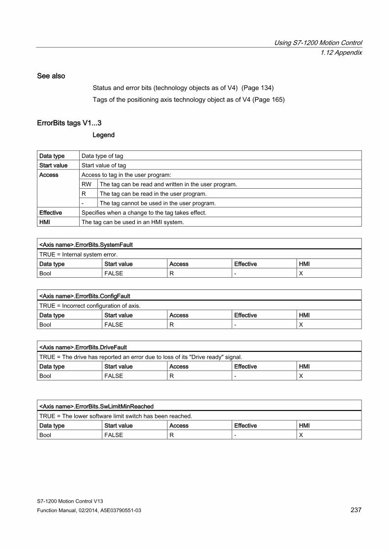
Using S7-1200 Motion Control 1.12 Appendix
S7-1200 Motion Control V13 Function Manual, 02/2014, A5E03790551-03 237
See also Status and error bits (technology objects as of V4) (Page 134)
Tags of the positioning axis technology object as of V4 (Page 165)
ErrorBits tags V1...3 Legend
Data type Data type of tag Start value Start value of tag Access Access to tag in the user program:
RW The tag can be read and written in the user program. R The tag can be read in the user program. - The tag cannot be used in the user program.
Effective Specifies when a change to the tag takes effect. HMI The tag can be used in an HMI system.
<Axis name>.ErrorBits.SystemFault TRUE = Internal system error. Data type Start value Access Effective HMI Bool FALSE R - X
<Axis name>.ErrorBits.ConfigFault TRUE = Incorrect configuration of axis. Data type Start value Access Effective HMI Bool FALSE R - X
<Axis name>.ErrorBits.DriveFault TRUE = The drive has reported an error due to loss of its "Drive ready" signal. Data type Start value Access Effective HMI Bool FALSE R - X
<Axis name>.ErrorBits.SwLimitMinReached TRUE = The lower software limit switch has been reached. Data type Start value Access Effective HMI Bool FALSE R - X

Using S7-1200 Motion Control 1.12 Appendix
S7-1200 Motion Control V13 238 Function Manual, 02/2014, A5E03790551-03
<Axis name>.ErrorBits.SwLimitMinExceeded TRUE = The lower software limit switch has been exceeded. Data type Start value Access Effective HMI Bool FALSE R - X
<Axis name>.ErrorBits.SwLimitMaxReached TRUE = The upper software limit switch has been reached. Data type Start value Access Effective HMI Bool FALSE R - X
<Axis name>.ErrorBits.SwLimitMaxExceeded TRUE = The upper software limit switch has been exceeded. Data type Start value Access Effective HMI Bool FALSE R - X
<Axis name>.ErrorBits.HwLimitMin TRUE = The lower hardware limit switch has been approached. Data type Start value Access Effective HMI Bool FALSE R - X
<Axis name>.ErrorBits.HwLimitMax TRUE = The upper hardware limit switch has been approached. Data type Start value Access Effective HMI Bool FALSE R - X
<Axis name>.ErrorBits.HwUsed TRUE = A second axis is using the same PTO (Pulse Train Output) and is enabled with "MC_Power". Data type Start value Access Effective HMI Bool FALSE R - X
See also Status and error bits (technology objects as of V4) (Page 134)
Tags of the positioning axis technology object as of V4 (Page 165)
Using S7-1200 Motion Control 1.12 Appendix
S7-1200 Motion Control V13 Function Manual, 02/2014, A5E03790551-03 239
Internal tags V1...3 The "Internal" tags contain no user-relevant data; these tags cannot be accessed in the user program.
See also Tags of the positioning axis technology object as of V4 (Page 165)
ControlPanel tags V1...3 The "ControlPanel" tags contain no user-relevant data; these tags cannot be accessed in the user program.
See also Tags of the positioning axis technology object as of V4 (Page 165)
Update of the technology object tags The status and error information of the axis indicated in the technology object tags is updated at each cycle control point.
The change in values of editable configuration tags does not take effect immediately. For information on the conditions under which a change takes effect, refer to the detailed description of the relevant tag.

Using S7-1200 Motion Control 1.12 Appendix
S7-1200 Motion Control V13 240 Function Manual, 02/2014, A5E03790551-03
1.12.10.6 Tags of the command table technology object V1...3
Config.Command.Command[1 ... 32] tags V1...3 Legend
Data type Data type of the tag Start value Start value of tag
The start value can be overwritten by the configuration of the command table. Access Access to the tag in the user program:
RW The tag can be read and written in the user program. R The tag can be read in the user program. - The tag cannot be used in the user program.
Effective Specifies when a change in the tag takes effect. HMI The tag can be used in an HMI system.
<Command table>.Config.Command.Command[x].Type Command type • 0 = "Empty" command • 2 = "Hold" command • 5 = "Relative positioning" command • 6 = "Absolute positioning" command • 7 = "Velocity setpoint" command • 151 = "Wait" command
Data type Start value Access Effective HMI Int 0 RW - X
<Command table>. Config.Command.Command[x].Position Command target position / travel path Data type Start value Access Effective HMI Real RW - X
<Command table>. Config.Command.Command[x].Velocity Command velocity Data type Start value Access Effective HMI Real 0.0 RW - X
<Command table>. Config.Command.Command[x].Duration Command duration Data type Start value Access Effective HMI Real 0.0 RW - X

Using S7-1200 Motion Control 1.12 Appendix
S7-1200 Motion Control V13 Function Manual, 02/2014, A5E03790551-03 241
<Command table>. Config.Command.Command[x].BufferMode Value for command "Next step" • 0 = "Complete command" • 1 = "Blend movement"
Data type Start value Access Effective HMI Int 0 RW - X
<Command table>. Config.Command.Command[x].StepCode Command step code Data type Start value Access Effective HMI Word 0 RW - X
See also Tags of the command table technology object as of V4 (Page 188)
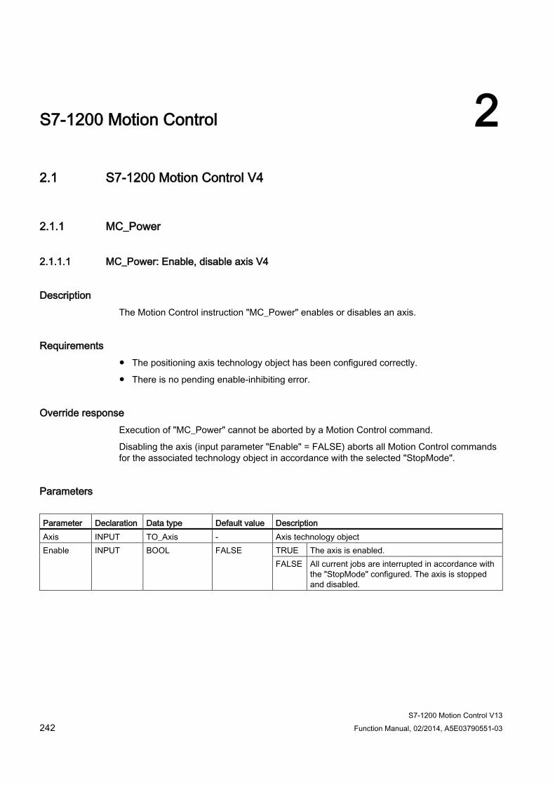
S7-1200 Motion Control V13 242 Function Manual, 02/2014, A5E03790551-03
S7-1200 Motion Control 2 2.1 S7-1200 Motion Control V4
2.1.1 MC_Power
2.1.1.1 MC_Power: Enable, disable axis V4
Description The Motion Control instruction "MC_Power" enables or disables an axis.
Requirements ● The positioning axis technology object has been configured correctly.
● There is no pending enable-inhibiting error.
Override response Execution of "MC_Power" cannot be aborted by a Motion Control command.
Disabling the axis (input parameter "Enable" = FALSE) aborts all Motion Control commands for the associated technology object in accordance with the selected "StopMode".
Parameters Parameter Declaration Data type Default value Description Axis INPUT TO_Axis - Axis technology object Enable INPUT BOOL FALSE TRUE The axis is enabled.
FALSE All current jobs are interrupted in accordance with the "StopMode" configured. The axis is stopped and disabled.
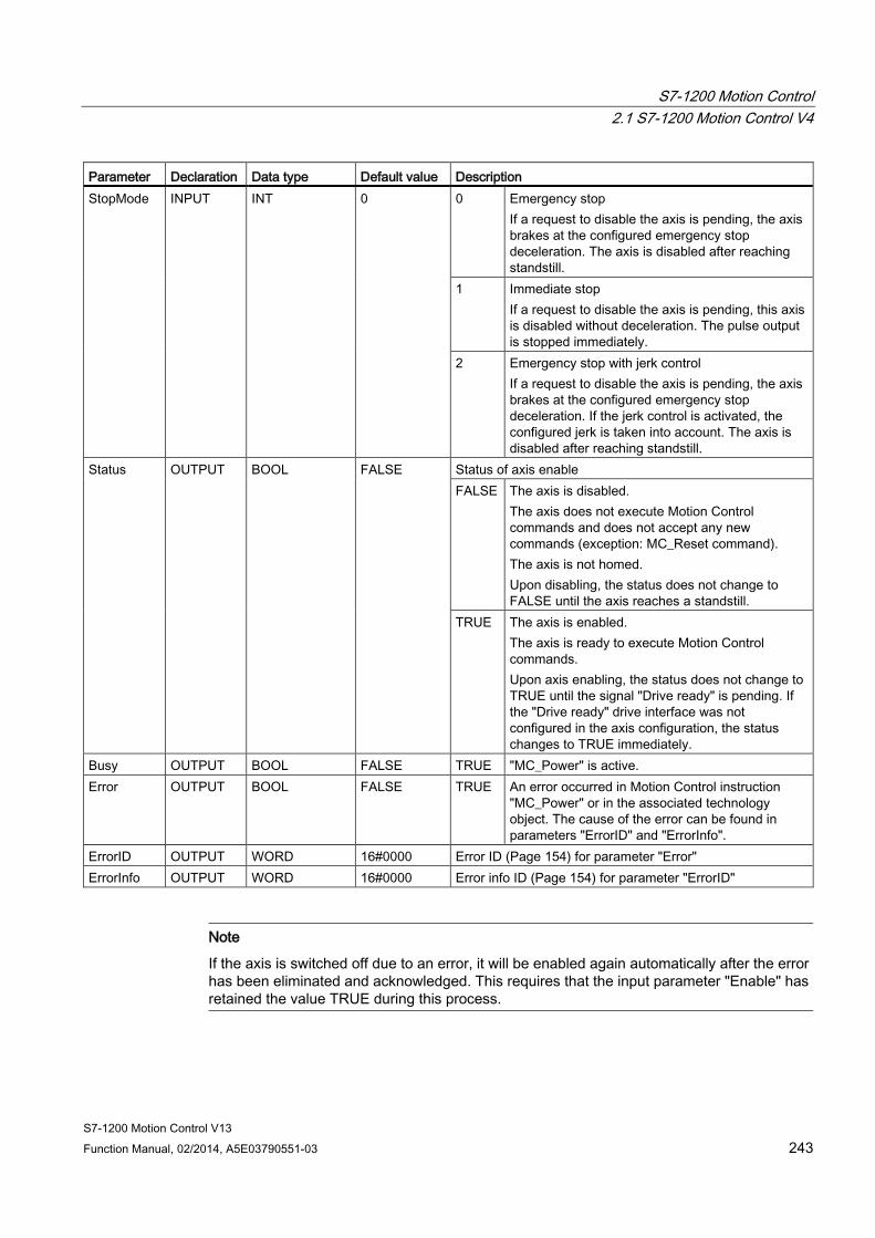
S7-1200 Motion Control 2.1 S7-1200 Motion Control V4
S7-1200 Motion Control V13 Function Manual, 02/2014, A5E03790551-03 243
Parameter Declaration Data type Default value Description StopMode INPUT INT 0 0 Emergency stop
If a request to disable the axis is pending, the axis brakes at the configured emergency stop deceleration. The axis is disabled after reaching standstill.
1 Immediate stop If a request to disable the axis is pending, this axis is disabled without deceleration. The pulse output is stopped immediately.
2 Emergency stop with jerk control If a request to disable the axis is pending, the axis brakes at the configured emergency stop deceleration. If the jerk control is activated, the configured jerk is taken into account. The axis is disabled after reaching standstill.
Status OUTPUT BOOL FALSE Status of axis enable FALSE The axis is disabled.
The axis does not execute Motion Control commands and does not accept any new commands (exception: MC_Reset command). The axis is not homed. Upon disabling, the status does not change to FALSE until the axis reaches a standstill.
TRUE The axis is enabled. The axis is ready to execute Motion Control commands. Upon axis enabling, the status does not change to TRUE until the signal "Drive ready" is pending. If the "Drive ready" drive interface was not configured in the axis configuration, the status changes to TRUE immediately.
Busy OUTPUT BOOL FALSE TRUE "MC_Power" is active. Error OUTPUT BOOL FALSE TRUE An error occurred in Motion Control instruction
"MC_Power" or in the associated technology object. The cause of the error can be found in parameters "ErrorID" and "ErrorInfo".
ErrorID OUTPUT WORD 16#0000 Error ID (Page 154) for parameter "Error" ErrorInfo OUTPUT WORD 16#0000 Error info ID (Page 154) for parameter "ErrorID"
Note
If the axis is switched off due to an error, it will be enabled again automatically after the error has been eliminated and acknowledged. This requires that the input parameter "Enable" has retained the value TRUE during this process.
S7-1200 Motion Control 2.1 S7-1200 Motion Control V4
S7-1200 Motion Control V13 244 Function Manual, 02/2014, A5E03790551-03
Enabling an axis with configured drive interface To enable the axis, follow these steps:
1. Check the requirements indicated above.
2. Initialize input parameter "StopMode" with the desired value. Set the input parameter "Enable" to TRUE.
The enable output for "Drive enabled" changes to TRUE to enable the power to the drive. The CPU waits for the "Drive ready" signal of the drive.
When the "Drive ready" signal is available at the configured ready input of the CPU, the axis is enabled. Output parameter "Status" and tag of technology object <Axis name>.StatusBits.Enable indicate the value TRUE.
Enabling an axis without configured drive interface To enable the axis, follow these steps:
1. Check the requirements indicated above.
2. Initialize input parameter "StopMode" with the desired value. Set the input parameter "Enable" to TRUE. The axis is enabled. The output parameter "Status" and the tag of the technology object <Axis name>.StatusBits.Enable indicate the value TRUE.
Disabling an axis To disable an axis, you can follow the steps described below:
1. Bring the axis to a standstill.
You can identify when the axis is at a standstill in the tag of the technology object <Axis name>.StatusBits.StandStill.
2. Set input parameter "Enable" to FALSE after standstill is reached.
3. If output parameters "Busy" and "Status" and tag of technology object <Axis name>.StatusBits.Enable indicate the value FALSE, disabling of the axis is complete.
S7-1200 Motion Control 2.1 S7-1200 Motion Control V4
S7-1200 Motion Control V13 Function Manual, 02/2014, A5E03790551-03 245
See also Overview of the Motion Control statements (Page 114)
List of ErrorIDs and ErrorInfos (technology objects as of V4) (Page 154)
MC_Power: Function chart V4 (Page 246)
MC_Reset: Acknowledge fault V4 (Page 247)
MC_Home: Home axes, set reference point V4 (Page 249)
MC_Halt: Halt axes V4 (Page 253)
MC_MoveAbsolute: Absolute positioning of axes V4 (Page 256)
MC_MoveRelative: Relative positioning of axes V4 (Page 260)
MC_MoveVelocity: Move axes at preset rotational speed V4 (Page 264)
MC_MoveJog: Move axes in jog mode V4 (Page 268)
MC_ChangeDynamic: Change dynamic settings of axis V4 (Page 275)
MC_CommandTable: Run axis commands as motion sequence V4 (Page 272)
MC_ReadParam: Continuously read motion data of a positioning axis V4 (Page 278)
MC_WriteParam: Write tag of positioning axis V4 (Page 280)
S7-1200 Motion Control V1...3 (Page 282)

S7-1200 Motion Control 2.1 S7-1200 Motion Control V4
S7-1200 Motion Control V13 246 Function Manual, 02/2014, A5E03790551-03
2.1.1.2 MC_Power: Function chart V4
Function chart
① An axis is enabled and then disabled again. When the drive has signaled "Drive ready" back to the CPU, the successful enable can be read out via "Status_1".
② Following an axis enable, an error has occurred that caused the axis to be disabled. The error is eliminated and acknowledged with "MC_Reset". The axis is then enabled again.
See also MC_Power: Enable, disable axis V4 (Page 242)
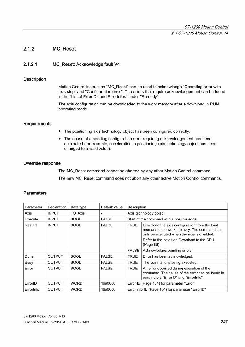
S7-1200 Motion Control 2.1 S7-1200 Motion Control V4
S7-1200 Motion Control V13 Function Manual, 02/2014, A5E03790551-03 247
2.1.2 MC_Reset
2.1.2.1 MC_Reset: Acknowledge fault V4
Description Motion Control instruction "MC_Reset" can be used to acknowledge "Operating error with axis stop" and "Configuration error". The errors that require acknowledgement can be found in the "List of ErrorIDs and ErrorInfos" under "Remedy".
The axis configuration can be downloaded to the work memory after a download in RUN operating mode.
Requirements ● The positioning axis technology object has been configured correctly.
● The cause of a pending configuration error requiring acknowledgement has been eliminated (for example, acceleration in positioning axis technology object has been changed to a valid value).
Override response The MC_Reset command cannot be aborted by any other Motion Control command.
The new MC_Reset command does not abort any other active Motion Control commands.
Parameters Parameter Declaration Data type Default value Description Axis INPUT TO_Axis - Axis technology object Execute INPUT BOOL FALSE Start of the command with a positive edge Restart INPUT BOOL FALSE TRUE Download the axis configuration from the load
memory to the work memory. The command can only be executed when the axis is disabled. Refer to the notes on Download to the CPU (Page 86).
FALSE Acknowledges pending errors Done OUTPUT BOOL FALSE TRUE Error has been acknowledged. Busy OUTPUT BOOL FALSE TRUE The command is being executed. Error OUTPUT BOOL FALSE TRUE An error occurred during execution of the
command. The cause of the error can be found in parameters "ErrorID" and "ErrorInfo".
ErrorID OUTPUT WORD 16#0000 Error ID (Page 154) for parameter "Error" ErrorInfo OUTPUT WORD 16#0000 Error info ID (Page 154) for parameter "ErrorID"
S7-1200 Motion Control 2.1 S7-1200 Motion Control V4
S7-1200 Motion Control V13 248 Function Manual, 02/2014, A5E03790551-03
Acknowledging an error requiring acknowledgement with MC_Reset To acknowledge an error, follow these steps:
1. Check the requirements indicated above.
2. Start the acknowledgement of the error with a rising edge at input parameter "Execute".
3. If output parameter "Done" indicates the value TRUE and tag of technology object <Axis name>.StatusBits.Error the value FALSE, the error has been acknowledged.
See also Overview of the Motion Control statements (Page 114)
List of ErrorIDs and ErrorInfos (technology objects as of V4) (Page 154)
Download to CPU (Page 86)
MC_Power: Enable, disable axis V4 (Page 242)
MC_Home: Home axes, set reference point V4 (Page 249)
MC_Halt: Halt axes V4 (Page 253)
MC_MoveAbsolute: Absolute positioning of axes V4 (Page 256)
MC_MoveRelative: Relative positioning of axes V4 (Page 260)
MC_MoveVelocity: Move axes at preset rotational speed V4 (Page 264)
MC_MoveJog: Move axes in jog mode V4 (Page 268)
MC_CommandTable: Run axis commands as motion sequence V4 (Page 272)
MC_ChangeDynamic: Change dynamic settings of axis V4 (Page 275)
MC_ReadParam: Continuously read motion data of a positioning axis V4 (Page 278)
MC_WriteParam: Write tag of positioning axis V4 (Page 280)
S7-1200 Motion Control V1...3 (Page 282)
S7-1200 Motion Control 2.1 S7-1200 Motion Control V4
S7-1200 Motion Control V13 Function Manual, 02/2014, A5E03790551-03 249
2.1.3 MC_Home
2.1.3.1 MC_Home: Home axes, set reference point V4
Description Motion Control instruction "MC_Home" is used to match the axis coordinates to the real, physical drive position. Homing is required for absolute positioning of the axis. The following types of homing can be executed:
● Active homing (Mode = 3)
The homing procedure is executed automatically.
● Passive homing (Mode = 2)
During passive homing, the "MC_Home" Motion Control instruction does not carry out any homing motion. The traversing motion required for this must be implemented by the user via other Motion Control instructions. When the homing switch is detected, the axis is homed.
● Direct homing absolute (Mode = 0)
The current axis position is set to the value of parameter "Position".
● Direct homing relative (Mode = 1)
The current axis position is offset by the value of parameter "Position".
Requirements ● The positioning axis technology object has been configured correctly.
● The axis is enabled.
● No MC_CommandTable command may be active upon start with Mode = 0, 1, or 2.
S7-1200 Motion Control 2.1 S7-1200 Motion Control V4
S7-1200 Motion Control V13 250 Function Manual, 02/2014, A5E03790551-03
Override response The override response depends on the selected mode:
Mode = 0, 1
The MC_Home command cannot be aborted by any other Motion Control command.
The MC_Home command does not abort any active Motion Control commands. Position-related motion commands are resumed after homing according to the new homing position (value at input parameter: "Position").
Mode = 2
The MC_Home command can be aborted by the following Motion Control commands:
● MC_Home command Mode = 2, 3
The new MC_Home command aborts the following active Motion Control command:
● MC_Home command Mode = 2
Position-related motion commands are resumed after homing according to the new homing position (value at input parameter: "Position").
Mode = 3
The MC_Home command can be aborted by the following Motion Control commands:
● MC_Home command Mode = 3
● MC_Halt command
● MC_MoveAbsolute command
● MC_MoveRelative command
● MC_MoveVelocity command
● MC_MoveJog command
● MC_CommandTable command
The new MC_Home command aborts the following active Motion Control commands:
● MC_Home command Mode = 2, 3
● MC_Halt command
● MC_MoveAbsolute command
● MC_MoveRelative command
● MC_MoveVelocity command
● MC_MoveJog command
● MC_CommandTable command

S7-1200 Motion Control 2.1 S7-1200 Motion Control V4
S7-1200 Motion Control V13 Function Manual, 02/2014, A5E03790551-03 251
Parameters Parameter Declaration Data type Default value Description Axis INPUT TO_Axis - Axis technology object Execute INPUT BOOL FALSE Start of the command with a positive edge Position INPUT REAL 0.0 • Mode = 0, 2, and 3
Absolute position of axis after completion of the homing operation
• Mode = 1
Correction value for the current axis position Limit values: -1.0e12 ≤ Position ≤ 1.0e12
Mode INPUT INT 0 Homing mode 0 Direct homing (absolute)
New axis position is the position value of parameter "Position".
1 Direct homing (relative) New axis position is the current axis position + position value of parameter "Position".
2 Passive homing Homing according to the axis configuration. Following homing, the value of parameter "Position" is set as the new axis position.
3 Active homing Homing procedure in accordance with the axis configuration. Following homing, the value of parameter "Position" is set as the new axis position.
Done OUTPUT BOOL FALSE TRUE Command completed Busy OUTPUT BOOL FALSE TRUE The command is being executed. CommandAborted OUTPUT BOOL FALSE TRUE During execution the command was
aborted by another command. Error OUTPUT BOOL FALSE TRUE An error occurred during execution of the
command. The cause of the error can be found in parameters "ErrorID" and "ErrorInfo".
ErrorID OUTPUT WORD 16#0000 Error ID (Page 154) for parameter "Error" ErrorInfo OUTPUT WORD 16#0000 Error info ID (Page 154) for parameter "ErrorID"
S7-1200 Motion Control 2.1 S7-1200 Motion Control V4
S7-1200 Motion Control V13 252 Function Manual, 02/2014, A5E03790551-03
Note
Axis homing is lost under the following conditions: • Disabling of axis by the "MC_Power" Motion Control instruction • Changeover between automatic mode and manual control • Upon start of active homing. After successful completion of the homing operation, axis
homing is again available. • After POWER OFF -> POWER ON of the CPU • After CPU restart (RUN-STOP -> STOP-RUN)
Homing an axis To home the axis, follow these stops:
1. Check the requirements indicated above.
2. Initialize the necessary input parameters with values, and start the homing operation with a rising edge at input parameter "Execute"
3. If output parameter "Done" and technology object tag <Axis name>.StatusBits.HomingDone indicate the value TRUE, homing is complete.
See also Overview of the Motion Control statements (Page 114)
List of ErrorIDs and ErrorInfos (technology objects as of V4) (Page 154)
MC_Power: Enable, disable axis V4 (Page 242)
MC_Reset: Acknowledge fault V4 (Page 247)
MC_Halt: Halt axes V4 (Page 253)
MC_MoveAbsolute: Absolute positioning of axes V4 (Page 256)
MC_MoveRelative: Relative positioning of axes V4 (Page 260)
MC_MoveVelocity: Move axes at preset rotational speed V4 (Page 264)
MC_MoveJog: Move axes in jog mode V4 (Page 268)
MC_CommandTable: Run axis commands as motion sequence V4 (Page 272)
MC_ChangeDynamic: Change dynamic settings of axis V4 (Page 275)
MC_ReadParam: Continuously read motion data of a positioning axis V4 (Page 278)
MC_WriteParam: Write tag of positioning axis V4 (Page 280)
S7-1200 Motion Control V1...3 (Page 282)
S7-1200 Motion Control 2.1 S7-1200 Motion Control V4
S7-1200 Motion Control V13 Function Manual, 02/2014, A5E03790551-03 253
2.1.4 MC_Halt
2.1.4.1 MC_Halt: Halt axes V4
Description The "MC_Halt" Motion Control instruction stops all movements and brings the axis to a standstill with the configured deceleration. The standstill position is not defined.
Requirements ● The positioning axis technology object has been configured correctly.
● The axis is enabled.
Override response The MC_Halt command can be aborted by the following Motion Control commands:
● MC_Home command Mode = 3
● MC_Halt command
● MC_MoveAbsolute command
● MC_MoveRelative command
● MC_MoveVelocity command
● MC_MoveJog command
● MC_CommandTable command
The new MC_Halt command aborts the following active Motion Control commands:
● MC_Home command Mode = 3
● MC_Halt command
● MC_MoveAbsolute command
● MC_MoveRelative command
● MC_MoveVelocity command
● MC_MoveJog command
● MC_CommandTable command
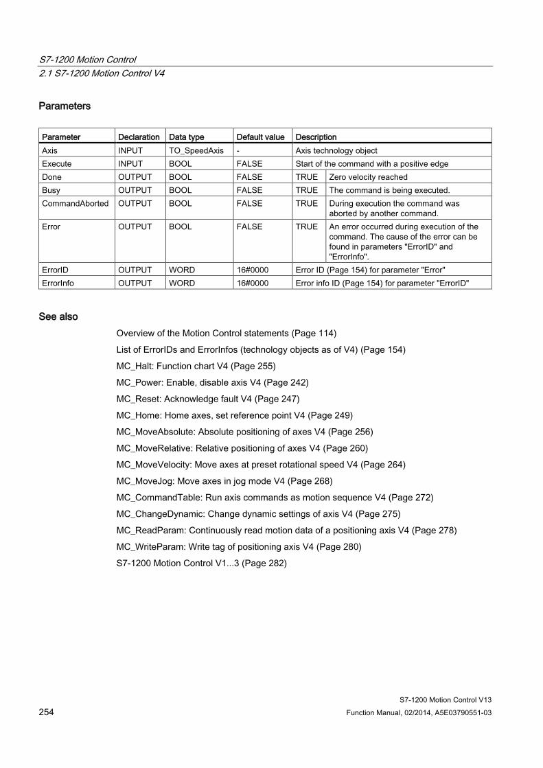
S7-1200 Motion Control 2.1 S7-1200 Motion Control V4
S7-1200 Motion Control V13 254 Function Manual, 02/2014, A5E03790551-03
Parameters Parameter Declaration Data type Default value Description Axis INPUT TO_SpeedAxis - Axis technology object Execute INPUT BOOL FALSE Start of the command with a positive edge Done OUTPUT BOOL FALSE TRUE Zero velocity reached Busy OUTPUT BOOL FALSE TRUE The command is being executed. CommandAborted OUTPUT BOOL FALSE TRUE During execution the command was
aborted by another command. Error OUTPUT BOOL FALSE TRUE An error occurred during execution of the
command. The cause of the error can be found in parameters "ErrorID" and "ErrorInfo".
ErrorID OUTPUT WORD 16#0000 Error ID (Page 154) for parameter "Error" ErrorInfo OUTPUT WORD 16#0000 Error info ID (Page 154) for parameter "ErrorID"
See also Overview of the Motion Control statements (Page 114)
List of ErrorIDs and ErrorInfos (technology objects as of V4) (Page 154)
MC_Halt: Function chart V4 (Page 255)
MC_Power: Enable, disable axis V4 (Page 242)
MC_Reset: Acknowledge fault V4 (Page 247)
MC_Home: Home axes, set reference point V4 (Page 249)
MC_MoveAbsolute: Absolute positioning of axes V4 (Page 256)
MC_MoveRelative: Relative positioning of axes V4 (Page 260)
MC_MoveVelocity: Move axes at preset rotational speed V4 (Page 264)
MC_MoveJog: Move axes in jog mode V4 (Page 268)
MC_CommandTable: Run axis commands as motion sequence V4 (Page 272)
MC_ChangeDynamic: Change dynamic settings of axis V4 (Page 275)
MC_ReadParam: Continuously read motion data of a positioning axis V4 (Page 278)
MC_WriteParam: Write tag of positioning axis V4 (Page 280)
S7-1200 Motion Control V1...3 (Page 282)
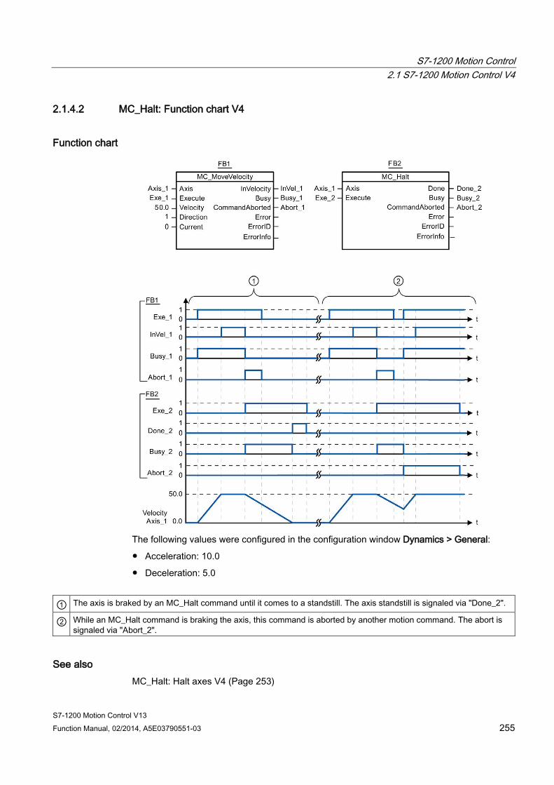
S7-1200 Motion Control 2.1 S7-1200 Motion Control V4
S7-1200 Motion Control V13 Function Manual, 02/2014, A5E03790551-03 255
2.1.4.2 MC_Halt: Function chart V4
Function chart
The following values were configured in the configuration window Dynamics > General:
● Acceleration: 10.0
● Deceleration: 5.0
① The axis is braked by an MC_Halt command until it comes to a standstill. The axis standstill is signaled via "Done_2".
② While an MC_Halt command is braking the axis, this command is aborted by another motion command. The abort is signaled via "Abort_2".
See also MC_Halt: Halt axes V4 (Page 253)

S7-1200 Motion Control 2.1 S7-1200 Motion Control V4
S7-1200 Motion Control V13 256 Function Manual, 02/2014, A5E03790551-03
2.1.5 MC_MoveAbsolute
2.1.5.1 MC_MoveAbsolute: Absolute positioning of axes V4
Description The "MC_MoveAbsolute" Motion Control instruction starts an axis positioning motion to move it to an absolute position.
Requirements ● The positioning axis technology object has been configured correctly.
● The axis is enabled.
● The axis is homed.
Override response The MC_MoveAbsolute command can be aborted by the following Motion Control commands:
● MC_Home command Mode = 3
● MC_Halt command
● MC_MoveAbsolute command
● MC_MoveRelative command
● MC_MoveVelocity command
● MC_MoveJog command
● MC_CommandTable command
The new MC_MoveAbsolute command aborts the following active Motion Control commands:
● MC_Home command Mode = 3
● MC_Halt command
● MC_MoveAbsolute command
● MC_MoveRelative command
● MC_MoveVelocity command
● MC_MoveJog command
● MC_CommandTable command

S7-1200 Motion Control 2.1 S7-1200 Motion Control V4
S7-1200 Motion Control V13 Function Manual, 02/2014, A5E03790551-03 257
Parameters Parameter Declaration Data type Default value Description Axis INPUT TO_PositioningA
xis - Axis technology object
Execute INPUT BOOL FALSE Start of the command with a positive edge Position INPUT REAL 0.0 Absolute target position
Limit values: -1.0e12 ≤ Position ≤ 1.0e12
Velocity INPUT REAL 10.0 Velocity of axis This velocity is not always reached on account of the configured acceleration and deceleration and the target position to be approached. Limit values: Start/stop velocity ≤ Velocity ≤ maximum velocity
Done OUTPUT BOOL FALSE TRUE Absolute target position reached Busy OUTPUT BOOL FALSE TRUE The command is being executed. CommandAborted OUTPUT BOOL FALSE TRUE During execution the command was
aborted by another command. Error OUTPUT BOOL FALSE TRUE An error occurred during execution of the
command. The cause of the error can be found in parameters "ErrorID" and "ErrorInfo".
ErrorID OUTPUT WORD 16#0000 Error ID (Page 154) for parameter "Error" ErrorInfo OUTPUT WORD 16#0000 Error info ID (Page 154) for parameter "ErrorID"
See also Overview of the Motion Control statements (Page 114) List of ErrorIDs and ErrorInfos (technology objects as of V4) (Page 154) MC_MoveAbsolute: Function chart V4 (Page 258) MC_Power: Enable, disable axis V4 (Page 242) MC_Reset: Acknowledge fault V4 (Page 247) MC_Home: Home axes, set reference point V4 (Page 249) MC_Halt: Halt axes V4 (Page 253) MC_MoveRelative: Relative positioning of axes V4 (Page 260) MC_MoveVelocity: Move axes at preset rotational speed V4 (Page 264) MC_MoveJog: Move axes in jog mode V4 (Page 268) MC_CommandTable: Run axis commands as motion sequence V4 (Page 272) MC_ChangeDynamic: Change dynamic settings of axis V4 (Page 275) MC_ReadParam: Continuously read motion data of a positioning axis V4 (Page 278) MC_WriteParam: Write tag of positioning axis V4 (Page 280) S7-1200 Motion Control V1...3 (Page 282)

S7-1200 Motion Control 2.1 S7-1200 Motion Control V4
S7-1200 Motion Control V13 258 Function Manual, 02/2014, A5E03790551-03
2.1.5.2 MC_MoveAbsolute: Function chart V4
Function chart
The following values were configured in the configuration window Dynamics > General:
● Acceleration: 10.0
● Deceleration: 10.0
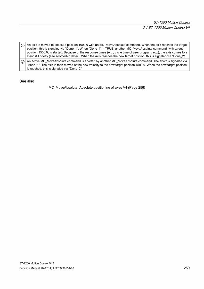
S7-1200 Motion Control 2.1 S7-1200 Motion Control V4
S7-1200 Motion Control V13 Function Manual, 02/2014, A5E03790551-03 259
① An axis is moved to absolute position 1000.0 with an MC_MoveAbsolute command. When the axis reaches the target position, this is signaled via "Done_1". When "Done_1" = TRUE, another MC_MoveAbsolute command, with target position 1500.0, is started. Because of the response times (e.g., cycle time of user program, etc.), the axis comes to a standstill briefly (see zoomed-in detail). When the axis reaches the new target position, this is signaled via "Done_2".
② An active MC_MoveAbsolute command is aborted by another MC_MoveAbsolute command. The abort is signaled via "Abort_1". The axis is then moved at the new velocity to the new target position 1500.0. When the new target position is reached, this is signaled via "Done_2".
See also MC_MoveAbsolute: Absolute positioning of axes V4 (Page 256)
S7-1200 Motion Control 2.1 S7-1200 Motion Control V4
S7-1200 Motion Control V13 260 Function Manual, 02/2014, A5E03790551-03
2.1.6 MC_MoveRelative
2.1.6.1 MC_MoveRelative: Relative positioning of axes V4
Description The "MC_MoveRelative" Motion Control instruction starts a positioning motion relative to the start position.
Requirements ● The positioning axis technology object has been configured correctly.
● The axis is enabled.
Override response The MC_MoveRelative command can be aborted by the following Motion Control commands:
● MC_Home command Mode = 3
● MC_Halt command
● MC_MoveAbsolute command
● MC_MoveRelative command
● MC_MoveVelocity command
● MC_MoveJog command
● MC_CommandTable command
The new MC_MoveRelative command aborts the following active Motion Control commands:
● MC_Home command Mode = 3
● MC_Halt command
● MC_MoveAbsolute command
● MC_MoveRelative command
● MC_MoveVelocity command
● MC_MoveJog command
● MC_CommandTable command
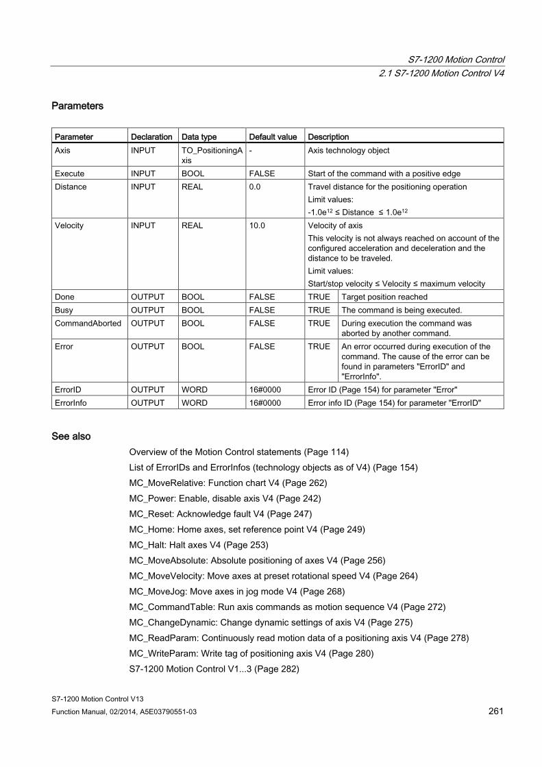
S7-1200 Motion Control 2.1 S7-1200 Motion Control V4
S7-1200 Motion Control V13 Function Manual, 02/2014, A5E03790551-03 261
Parameters Parameter Declaration Data type Default value Description Axis INPUT TO_PositioningA
xis - Axis technology object
Execute INPUT BOOL FALSE Start of the command with a positive edge Distance INPUT REAL 0.0 Travel distance for the positioning operation
Limit values: -1.0e12 ≤ Distance ≤ 1.0e12
Velocity INPUT REAL 10.0 Velocity of axis This velocity is not always reached on account of the configured acceleration and deceleration and the distance to be traveled. Limit values: Start/stop velocity ≤ Velocity ≤ maximum velocity
Done OUTPUT BOOL FALSE TRUE Target position reached Busy OUTPUT BOOL FALSE TRUE The command is being executed. CommandAborted OUTPUT BOOL FALSE TRUE During execution the command was
aborted by another command. Error OUTPUT BOOL FALSE TRUE An error occurred during execution of the
command. The cause of the error can be found in parameters "ErrorID" and "ErrorInfo".
ErrorID OUTPUT WORD 16#0000 Error ID (Page 154) for parameter "Error" ErrorInfo OUTPUT WORD 16#0000 Error info ID (Page 154) for parameter "ErrorID"
See also Overview of the Motion Control statements (Page 114) List of ErrorIDs and ErrorInfos (technology objects as of V4) (Page 154) MC_MoveRelative: Function chart V4 (Page 262) MC_Power: Enable, disable axis V4 (Page 242) MC_Reset: Acknowledge fault V4 (Page 247) MC_Home: Home axes, set reference point V4 (Page 249) MC_Halt: Halt axes V4 (Page 253) MC_MoveAbsolute: Absolute positioning of axes V4 (Page 256) MC_MoveVelocity: Move axes at preset rotational speed V4 (Page 264) MC_MoveJog: Move axes in jog mode V4 (Page 268) MC_CommandTable: Run axis commands as motion sequence V4 (Page 272) MC_ChangeDynamic: Change dynamic settings of axis V4 (Page 275) MC_ReadParam: Continuously read motion data of a positioning axis V4 (Page 278) MC_WriteParam: Write tag of positioning axis V4 (Page 280) S7-1200 Motion Control V1...3 (Page 282)

S7-1200 Motion Control 2.1 S7-1200 Motion Control V4
S7-1200 Motion Control V13 262 Function Manual, 02/2014, A5E03790551-03
2.1.6.2 MC_MoveRelative: Function chart V4
Function chart
The following values were configured in the configuration window Dynamics > General:
● Acceleration: 10.0
● Deceleration: 10.0
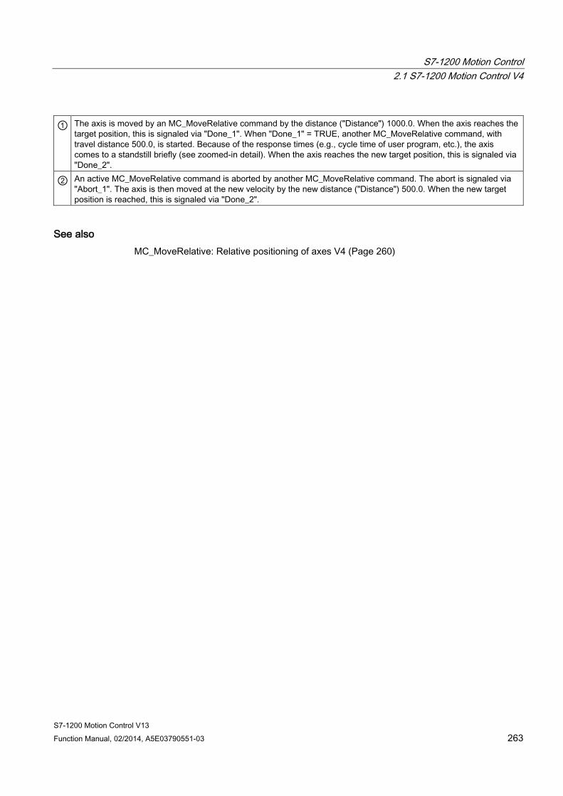
S7-1200 Motion Control 2.1 S7-1200 Motion Control V4
S7-1200 Motion Control V13 Function Manual, 02/2014, A5E03790551-03 263
① The axis is moved by an MC_MoveRelative command by the distance ("Distance") 1000.0. When the axis reaches the target position, this is signaled via "Done_1". When "Done_1" = TRUE, another MC_MoveRelative command, with travel distance 500.0, is started. Because of the response times (e.g., cycle time of user program, etc.), the axis comes to a standstill briefly (see zoomed-in detail). When the axis reaches the new target position, this is signaled via "Done_2".
② An active MC_MoveRelative command is aborted by another MC_MoveRelative command. The abort is signaled via "Abort_1". The axis is then moved at the new velocity by the new distance ("Distance") 500.0. When the new target position is reached, this is signaled via "Done_2".
See also MC_MoveRelative: Relative positioning of axes V4 (Page 260)

S7-1200 Motion Control 2.1 S7-1200 Motion Control V4
S7-1200 Motion Control V13 264 Function Manual, 02/2014, A5E03790551-03
2.1.7 MC_MoveVelocity
2.1.7.1 MC_MoveVelocity: Move axes at preset rotational speed V4
Description The Motion Control instruction "MC_MoveVelocity" moves the axis constantly at the specified velocity.
Requirements ● The positioning axis technology object has been configured correctly.
● The axis is enabled.
Override response MC_MoveVelocity can be aborted by the following Motion Control commands:
● MC_Home command Mode = 3
● MC_Halt command
● MC_MoveAbsolute command
● MC_MoveRelative command
● MC_MoveVelocity command
● MC_MoveJog command
● MC_CommandTable command
The new MC_MoveVelocity command aborts the following active Motion Control commands:
● MC_Home command Mode = 3
● MC_Halt command
● MC_MoveAbsolute command
● MC_MoveRelative command
● MC_MoveVelocity command
● MC_MoveJog command
● MC_CommandTable command
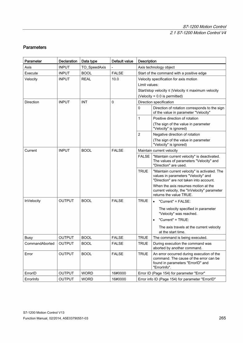
S7-1200 Motion Control 2.1 S7-1200 Motion Control V4
S7-1200 Motion Control V13 Function Manual, 02/2014, A5E03790551-03 265
Parameters Parameter Declaration Data type Default value Description Axis INPUT TO_SpeedAxis - Axis technology object Execute INPUT BOOL FALSE Start of the command with a positive edge Velocity INPUT REAL 10.0 Velocity specification for axis motion
Limit values: Start/stop velocity ≤ |Velocity ≤ maximum velocity (Velocity = 0.0 is permitted)
Direction INPUT INT 0 Direction specification 0 Direction of rotation corresponds to the sign
of the value in parameter "Velocity" 1 Positive direction of rotation
(The sign of the value in parameter "Velocity" is ignored)
2 Negative direction of rotation (The sign of the value in parameter "Velocity" is ignored)
Current INPUT BOOL FALSE Maintain current velocity FALSE "Maintain current velocity" is deactivated.
The values of parameters "Velocity" and "Direction" are used.
TRUE "Maintain current velocity" is activated. The values in parameters "Velocity" and "Direction" are not taken into account. When the axis resumes motion at the current velocity, the "InVelocity" parameter returns the value TRUE.
InVelocity OUTPUT BOOL FALSE TRUE • "Current" = FALSE:
The velocity specified in parameter "Velocity" was reached.
• "Current" = TRUE:
The axis travels at the current velocity at the start time.
Busy OUTPUT BOOL FALSE TRUE The command is being executed. CommandAborted OUTPUT BOOL FALSE TRUE During execution the command was
aborted by another command. Error OUTPUT BOOL FALSE TRUE An error occurred during execution of the
command. The cause of the error can be found in parameters "ErrorID" and "ErrorInfo".
ErrorID OUTPUT WORD 16#0000 Error ID (Page 154) for parameter "Error" ErrorInfo OUTPUT WORD 16#0000 Error info ID (Page 154) for parameter "ErrorID"

S7-1200 Motion Control 2.1 S7-1200 Motion Control V4
S7-1200 Motion Control V13 266 Function Manual, 02/2014, A5E03790551-03
Note PLCopen Version 2.0
The Motion Control instruction "MC_MoveVelocity" is compatible to PLCopen Version 2.0 as of V4.
The "InVelocity" and "Busy" parameters show their status regardless of the "Execute" parameter until the command is overridden or stopped by an error. For more information, refer to the section " Tracking active commands (Page 125).
Behavior with zero setpoint velocity (Velocity = 0.0) An MC_MoveVelocity command with "Velocity" = 0.0 (such as an MC_Halt command) aborts active motion commands and stops the axis with the configured deceleration.
When the axis comes to a standstill, output parameter "InVelocity" indicates TRUE for at least one program cycle.
"Busy" indicates the value TRUE during the deceleration process and changes to FALSE together with "InVelocity". If parameter "Execute" = TRUE is set, "InVelocity" and "Busy" are latched.
When the "MC_MoveVelocity" command is started, status bit "SpeedCommand" is set in the technology object. Status bit "ConstantVelocity" is set upon axis standstill. Both bits are adapted to the new situation when a new motion command is started.
See also Overview of the Motion Control statements (Page 114)
List of ErrorIDs and ErrorInfos (technology objects as of V4) (Page 154)
MC_MoveVelocity: Function chart V4 (Page 267)
MC_Power: Enable, disable axis V4 (Page 242)
MC_Reset: Acknowledge fault V4 (Page 247)
MC_Home: Home axes, set reference point V4 (Page 249)
MC_Halt: Halt axes V4 (Page 253)
MC_MoveAbsolute: Absolute positioning of axes V4 (Page 256)
MC_MoveRelative: Relative positioning of axes V4 (Page 260)
MC_MoveJog: Move axes in jog mode V4 (Page 268)
MC_CommandTable: Run axis commands as motion sequence V4 (Page 272)
MC_ChangeDynamic: Change dynamic settings of axis V4 (Page 275)
MC_ReadParam: Continuously read motion data of a positioning axis V4 (Page 278)
MC_WriteParam: Write tag of positioning axis V4 (Page 280)
S7-1200 Motion Control V1...3 (Page 282)
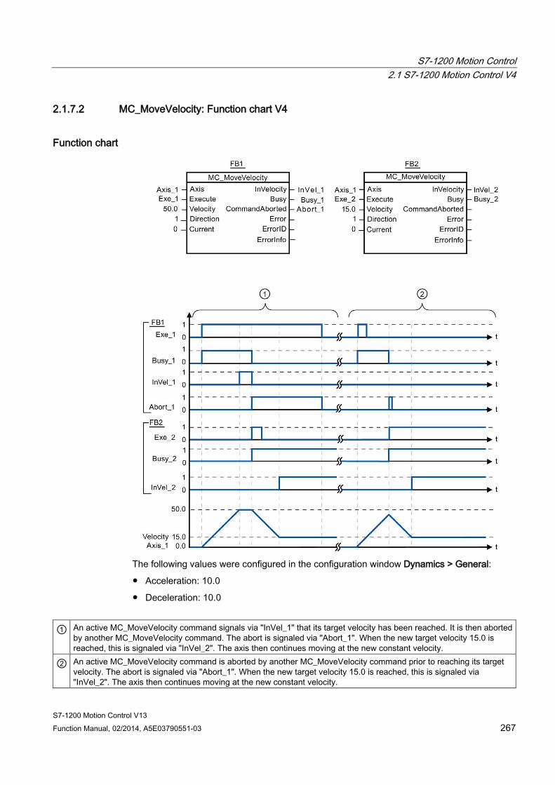
S7-1200 Motion Control 2.1 S7-1200 Motion Control V4
S7-1200 Motion Control V13 Function Manual, 02/2014, A5E03790551-03 267
2.1.7.2 MC_MoveVelocity: Function chart V4
Function chart
The following values were configured in the configuration window Dynamics > General:
● Acceleration: 10.0
● Deceleration: 10.0
① An active MC_MoveVelocity command signals via "InVel_1" that its target velocity has been reached. It is then aborted by another MC_MoveVelocity command. The abort is signaled via "Abort_1". When the new target velocity 15.0 is reached, this is signaled via "InVel_2". The axis then continues moving at the new constant velocity.
② An active MC_MoveVelocity command is aborted by another MC_MoveVelocity command prior to reaching its target velocity. The abort is signaled via "Abort_1". When the new target velocity 15.0 is reached, this is signaled via "InVel_2". The axis then continues moving at the new constant velocity.
S7-1200 Motion Control 2.1 S7-1200 Motion Control V4
S7-1200 Motion Control V13 268 Function Manual, 02/2014, A5E03790551-03
See also MC_MoveVelocity: Move axes at preset rotational speed V4 (Page 264)
2.1.8 MC_MoveJog
2.1.8.1 MC_MoveJog: Move axes in jog mode V4
Description Motion control instruction "MC_MoveJog" moves the axis constantly at the specified velocity in jog mode. You use this Motion Control instruction, for example, for testing and commissioning purposes.
Requirements ● The positioning axis technology object has been configured correctly.
● The axis is enabled.
Override response The MC_MoveJog command can be aborted by the following Motion Control commands:
● MC_Home command Mode = 3
● MC_Halt command
● MC_MoveAbsolute command
● MC_MoveRelative command
● MC_MoveVelocity command
● MC_MoveJog command
● MC_CommandTable command
The new MC_MoveJog command aborts the following active Motion Control commands:
● MC_Home command Mode = 3
● MC_Halt command
● MC_MoveAbsolute command
● MC_MoveRelative command
● MC_MoveVelocity command
● MC_MoveJog command
● MC_CommandTable command
S7-1200 Motion Control 2.1 S7-1200 Motion Control V4
S7-1200 Motion Control V13 Function Manual, 02/2014, A5E03790551-03 269
Parameters Parameter Declaration Data type Default value Description Axis INPUT TO_SpeedAxis - Axis technology object JogForward INPUT BOOL FALSE As long as the parameter is TRUE, the axis moves in
the positive direction at the velocity specified in parameter "Velocity".
JogBackward INPUT BOOL FALSE As long as the parameter is TRUE, the axis moves in the negative direction at the velocity specified in parameter "Velocity".
If both parameters are simultaneously TRUE, the axis stops with the configured deceleration. An error is indicated in parameters "Error", "ErrorID", and "ErrorInfo". Velocity INPUT REAL 10.0 Preset velocity for jog mode
Limit values: Start/stop velocity ≤ velocity ≤ maximum velocity
InVelocity OUTPUT BOOL FALSE TRUE The velocity specified in parameter "Velocity" was reached.
Busy OUTPUT BOOL FALSE TRUE The command is being executed. CommandAborted OUTPUT BOOL FALSE TRUE During execution the command was
aborted by another command. Error OUTPUT BOOL FALSE TRUE An error occurred during execution of the
command. The cause of the error can be found in parameters "ErrorID" and "ErrorInfo".
ErrorID OUTPUT WORD 16#0000 Error ID (Page 154) for parameter "Error" ErrorInfo OUTPUT WORD 16#0000 Error info ID (Page 154) for parameter "ErrorID"
S7-1200 Motion Control 2.1 S7-1200 Motion Control V4
S7-1200 Motion Control V13 270 Function Manual, 02/2014, A5E03790551-03
See also Overview of the Motion Control statements (Page 114)
List of ErrorIDs and ErrorInfos (technology objects as of V4) (Page 154)
MC_MoveJog: Function chart V4 (Page 271)
MC_Power: Enable, disable axis V4 (Page 242)
MC_Reset: Acknowledge fault V4 (Page 247)
MC_Home: Home axes, set reference point V4 (Page 249)
MC_Halt: Halt axes V4 (Page 253)
MC_MoveAbsolute: Absolute positioning of axes V4 (Page 256)
MC_MoveRelative: Relative positioning of axes V4 (Page 260)
MC_MoveVelocity: Move axes at preset rotational speed V4 (Page 264)
MC_CommandTable: Run axis commands as motion sequence V4 (Page 272)
MC_ChangeDynamic: Change dynamic settings of axis V4 (Page 275)
MC_ReadParam: Continuously read motion data of a positioning axis V4 (Page 278)
MC_WriteParam: Write tag of positioning axis V4 (Page 280)
S7-1200 Motion Control V1...3 (Page 282)
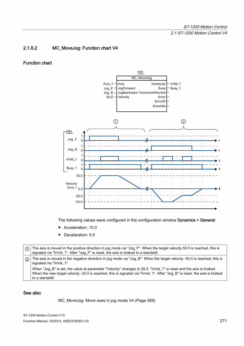
S7-1200 Motion Control 2.1 S7-1200 Motion Control V4
S7-1200 Motion Control V13 Function Manual, 02/2014, A5E03790551-03 271
2.1.8.2 MC_MoveJog: Function chart V4
Function chart
The following values were configured in the configuration window Dynamics > General:
● Acceleration: 10.0
● Deceleration: 5.0
① The axis is moved in the positive direction in jog mode via "Jog_F". When the target velocity 50.0 is reached, this is signaled via "InVel_1". After "Jog_F" is reset, the axis is braked to a standstill.
② The axis is moved in the negative direction in jog mode via "Jog_B". When the target velocity -50.0 is reached, this is signaled via "InVel_1". When "Jog_B" is set, the value at parameter "Velocity" changes to 25.0. "InVel_1" is reset and the axis is braked. When the new target velocity -25.0 is reached, this is signaled via "InVel_1". After "Jog_B" is reset, the axis is braked to a standstill.
See also MC_MoveJog: Move axes in jog mode V4 (Page 268)
S7-1200 Motion Control 2.1 S7-1200 Motion Control V4
S7-1200 Motion Control V13 272 Function Manual, 02/2014, A5E03790551-03
2.1.9 MC_CommandTable
2.1.9.1 MC_CommandTable: Run axis commands as motion sequence V4
Description The Motion Control instruction "MC_CommandTable" combines multiple individual axis control commands in one movement sequence.
Requirements ● The positioning axis technology object has been inserted and correctly configured.
● The command table technology object has been inserted and correctly configured.
● The axis is enabled.
Override response The MC_CommandTable command can be aborted by the following Motion Control commands:
● MC_Home command Mode = 3
● MC_Halt command
● MC_MoveAbsolute command
● MC_MoveRelative command
● MC_MoveVelocity command
● MC_MoveJog command
● MC_CommandTable command
The new MC_CommandTable command aborts the following active Motion Control commands:
● MC_Home command Mode = 3
● MC_Halt command
● MC_MoveAbsolute command
● MC_MoveRelative command
● MC_MoveVelocity command
● MC_MoveJog command
● MC_CommandTable command
The active Motion Control command is cancelled by the start of the first "Positioning Relative", "Positioning Absolute", "Velocity set point" or "Halt" command.

S7-1200 Motion Control 2.1 S7-1200 Motion Control V4
S7-1200 Motion Control V13 Function Manual, 02/2014, A5E03790551-03 273
Parameters Parameter Declaration Data type Default value Description Axis INPUT TO_SpeedAxis - Axis technology object Command Table
INPUT TO_CommandTable
- Command table technology object
Execute INPUT BOOL FALSE Command table start with positive edge StartStep INPUT INT 1 Defines the step at which the execution of the command
table should begin Limit values: 1 ≤ StartStep ≤ EndStep
EndStep INPUT INT 32 Defines the step up to which the execution of command table should take place Limit values: StartStep ≤ EndStep ≤ 32
Done OUTPUT BOOL FALSE TRUE Command table has been successfully executed
Busy OUTPU BOOL FALSE TRUE The command table is being executed. Command Aborted
OUTPUT BOOL FALSE TRUE The command table was cancelled by another command.
Error OUTPUT BOOL FALSE TRUE An error occurred during execution of the command table. The cause of the error can be found in parameters "ErrorID" and "ErrorInfo".
ErrorID OUTPUT WORD 16#0000 Error ID (Page 154) for parameter "Error" ErrorInfo OUTPUT WORD 16#0000 Error info ID (Page 154) for parameter "ErrorID" CurrentStep OUTPUT INT 0 Step in command table currently being executed StepCode OUTPUT WORD 16#0000 User-defined numerical value / bit pattern of the step
currently being executed
S7-1200 Motion Control 2.1 S7-1200 Motion Control V4
S7-1200 Motion Control V13 274 Function Manual, 02/2014, A5E03790551-03
See also Overview of the Motion Control statements (Page 114)
List of ErrorIDs and ErrorInfos (technology objects as of V4) (Page 154)
MC_Power: Enable, disable axis V4 (Page 242)
MC_Reset: Acknowledge fault V4 (Page 247)
MC_Home: Home axes, set reference point V4 (Page 249)
MC_Halt: Halt axes V4 (Page 253)
MC_MoveAbsolute: Absolute positioning of axes V4 (Page 256)
MC_MoveRelative: Relative positioning of axes V4 (Page 260)
MC_MoveVelocity: Move axes at preset rotational speed V4 (Page 264)
MC_MoveJog: Move axes in jog mode V4 (Page 268)
MC_ChangeDynamic: Change dynamic settings of axis V4 (Page 275)
MC_ReadParam: Continuously read motion data of a positioning axis V4 (Page 278)
MC_WriteParam: Write tag of positioning axis V4 (Page 280)
S7-1200 Motion Control V1...3 (Page 282)
S7-1200 Motion Control 2.1 S7-1200 Motion Control V4
S7-1200 Motion Control V13 Function Manual, 02/2014, A5E03790551-03 275
2.1.10 MC_ChangeDynamic
2.1.10.1 MC_ChangeDynamic: Change dynamic settings of axis V4
Description Motion Control instruction "MC_ChangeDynamic" allows you to change the following settings of the axis: ● Change the ramp-up time (acceleration) value ● Change the ramp-down time (deceleration) value ● Change the emergency stop ramp-down time (emergency stop deceleration) value ● Change the smoothing time (jerk) value
For the effectiveness of the change, refer to the description of the tag (Page 165).
Requirements The positioning axis technology object has been configured correctly.
Override response A MC_ChangeDynamic command cannot be aborted by any other Motion Control command.
A new MC_ChangeDynamic command does not abort any active Motion Control commands.
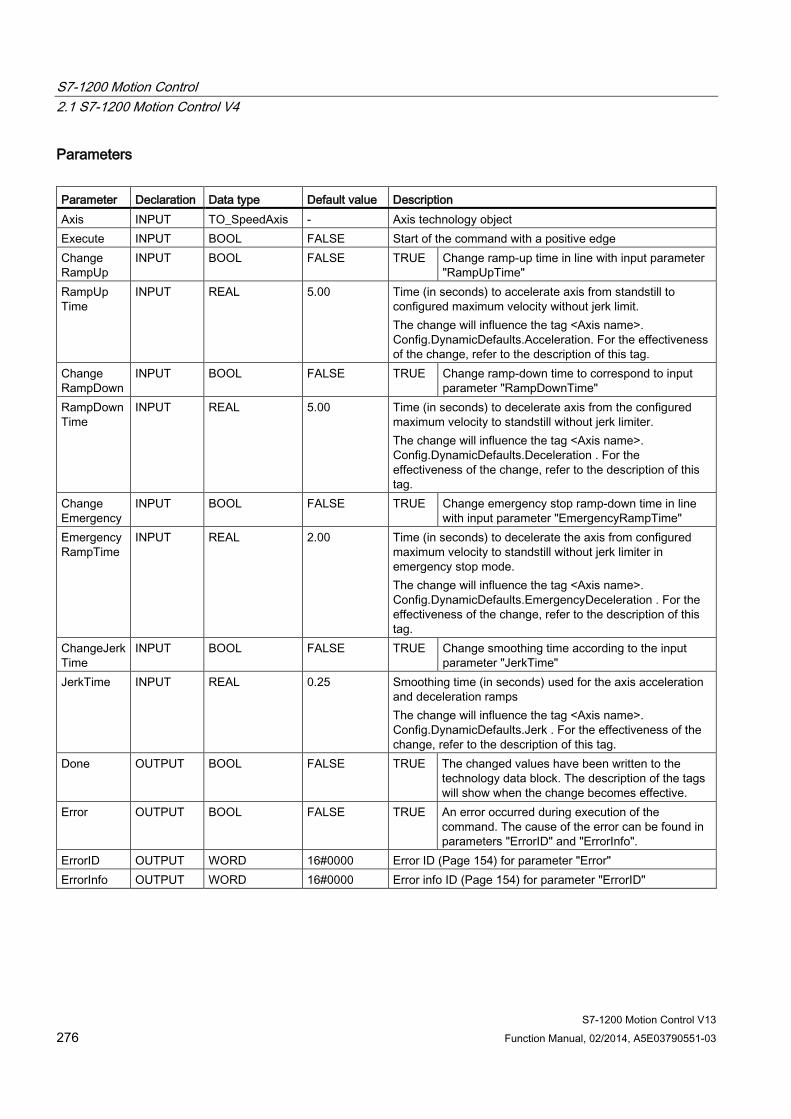
S7-1200 Motion Control 2.1 S7-1200 Motion Control V4
S7-1200 Motion Control V13 276 Function Manual, 02/2014, A5E03790551-03
Parameters Parameter Declaration Data type Default value Description Axis INPUT TO_SpeedAxis - Axis technology object Execute INPUT BOOL FALSE Start of the command with a positive edge Change RampUp
INPUT BOOL FALSE TRUE Change ramp-up time in line with input parameter "RampUpTime"
RampUp Time
INPUT REAL 5.00 Time (in seconds) to accelerate axis from standstill to configured maximum velocity without jerk limit. The change will influence the tag <Axis name>. Config.DynamicDefaults.Acceleration. For the effectiveness of the change, refer to the description of this tag.
Change RampDown
INPUT BOOL FALSE TRUE Change ramp-down time to correspond to input parameter "RampDownTime"
RampDownTime
INPUT REAL 5.00 Time (in seconds) to decelerate axis from the configured maximum velocity to standstill without jerk limiter. The change will influence the tag <Axis name>. Config.DynamicDefaults.Deceleration . For the effectiveness of the change, refer to the description of this tag.
Change Emergency
INPUT BOOL FALSE TRUE Change emergency stop ramp-down time in line with input parameter "EmergencyRampTime"
EmergencyRampTime
INPUT REAL 2.00 Time (in seconds) to decelerate the axis from configured maximum velocity to standstill without jerk limiter in emergency stop mode. The change will influence the tag <Axis name>. Config.DynamicDefaults.EmergencyDeceleration . For the effectiveness of the change, refer to the description of this tag.
ChangeJerkTime
INPUT BOOL FALSE TRUE Change smoothing time according to the input parameter "JerkTime"
JerkTime INPUT REAL 0.25 Smoothing time (in seconds) used for the axis acceleration and deceleration ramps The change will influence the tag <Axis name>. Config.DynamicDefaults.Jerk . For the effectiveness of the change, refer to the description of this tag.
Done OUTPUT BOOL FALSE TRUE The changed values have been written to the technology data block. The description of the tags will show when the change becomes effective.
Error OUTPUT BOOL FALSE TRUE An error occurred during execution of the command. The cause of the error can be found in parameters "ErrorID" and "ErrorInfo".
ErrorID OUTPUT WORD 16#0000 Error ID (Page 154) for parameter "Error" ErrorInfo OUTPUT WORD 16#0000 Error info ID (Page 154) for parameter "ErrorID"
S7-1200 Motion Control 2.1 S7-1200 Motion Control V4
S7-1200 Motion Control V13 Function Manual, 02/2014, A5E03790551-03 277
Note
At the input parameters "RampUpTime", "RampDownTime", "EmergencyRampTime" and "JerkTime", values can be entered which exceed the admissible limits of the resulting parameters: "Acceleration", "Deceleration", "Emergency stop deceleration" and "Jerk".
Ensure that your inputs are within the valid range, taking into consideration the equations and limits in section "Dynamic (Page 50)".
See also Overview of the Motion Control statements (Page 114)
List of ErrorIDs and ErrorInfos (technology objects as of V4) (Page 154)
Changing the configuration of dynamics in the user program (Page 56)
Changing the homing configuration in the user program (Page 64)
Tags of the positioning axis technology object as of V4 (Page 165)
MC_Power: Enable, disable axis V4 (Page 242)
MC_Reset: Acknowledge fault V4 (Page 247)
MC_Home: Home axes, set reference point V4 (Page 249)
MC_Halt: Halt axes V4 (Page 253)
MC_MoveAbsolute: Absolute positioning of axes V4 (Page 256)
MC_MoveRelative: Relative positioning of axes V4 (Page 260)
MC_MoveVelocity: Move axes at preset rotational speed V4 (Page 264)
MC_MoveJog: Move axes in jog mode V4 (Page 268)
MC_CommandTable: Run axis commands as motion sequence V4 (Page 272)
MC_ReadParam: Continuously read motion data of a positioning axis V4 (Page 278)
MC_WriteParam: Write tag of positioning axis V4 (Page 280)
S7-1200 Motion Control V1...3 (Page 282)
S7-1200 Motion Control 2.1 S7-1200 Motion Control V4
S7-1200 Motion Control V13 278 Function Manual, 02/2014, A5E03790551-03
2.1.11 MC_ReadParam
2.1.11.1 MC_ReadParam: Continuously read motion data of a positioning axis V4
Description Motion Control instruction "MC_ReadParam" enables continuous reading of motion data of an axis. The current value of the corresponding tag is determined at the start of the command.
The following motion data can be read:
● Current position of the axis
● Current velocity of the axis
● Current distance of axis from target position
● Target position of the axis
Requirements The positioning axis technology object has been configured correctly.
Override response A MC_ReadParam command cannot be aborted by any other Motion Control command.
A new MC_ReadParam command does not abort any active Motion Control commands.

S7-1200 Motion Control 2.1 S7-1200 Motion Control V4
S7-1200 Motion Control V13 Function Manual, 02/2014, A5E03790551-03 279
Parameters Parameter Declaration Data type Default
value Description
Enable INPUT BOOL FALSE TRUE Read the tag specified with the "Parameter" and store the value in the destination address specified with "Value".
FALSE Do not update assigned motion data Parameter INPUT VARIANT
(REAL) - VARIANT pointer to the value to be read. The following
tags are permitted: • <Axis name>.Position • <Axis name>.Velocity • <Axis name>.StatusPositioning.Distance • <Axis name>.StatusPositioning.TargetPosition
Value INOUT VARIANT (REAL)
- VARIANT pointer to the target tag or destination address to which the read value is to be written.
Valid OUTPUT BOOL FALSE TRUE The read value is valid. FALSE The read value is invalid.
Busy OUTPUT BOOL FALSE TRUE The command is being executed. Error OUTPUT BOOL FALSE TRUE An error occurred during execution of the
command. The cause of the error can be found in parameters "ErrorID" and "ErrorInfo".
ErrorID OUTPUT WORD 16#0000 Error ID (Page 154) for parameter "Error" ErrorInfo OUTPUT WORD 16#0000 Error info ID (Page 154) for parameter "ErrorID"
See also Overview of the Motion Control statements (Page 114)
List of ErrorIDs and ErrorInfos (technology objects as of V4) (Page 154)
S7-1200 Motion Control V1...3 (Page 282)
MC_Power: Enable, disable axis V4 (Page 242)
MC_Reset: Acknowledge fault V4 (Page 247)
MC_Home: Home axes, set reference point V4 (Page 249)
MC_Halt: Halt axes V4 (Page 253)
MC_MoveAbsolute: Absolute positioning of axes V4 (Page 256)
MC_MoveRelative: Relative positioning of axes V4 (Page 260)
MC_MoveVelocity: Move axes at preset rotational speed V4 (Page 264)
MC_MoveJog: Move axes in jog mode V4 (Page 268)
MC_CommandTable: Run axis commands as motion sequence V4 (Page 272)
MC_ChangeDynamic: Change dynamic settings of axis V4 (Page 275)
MC_WriteParam: Write tag of positioning axis V4 (Page 280)
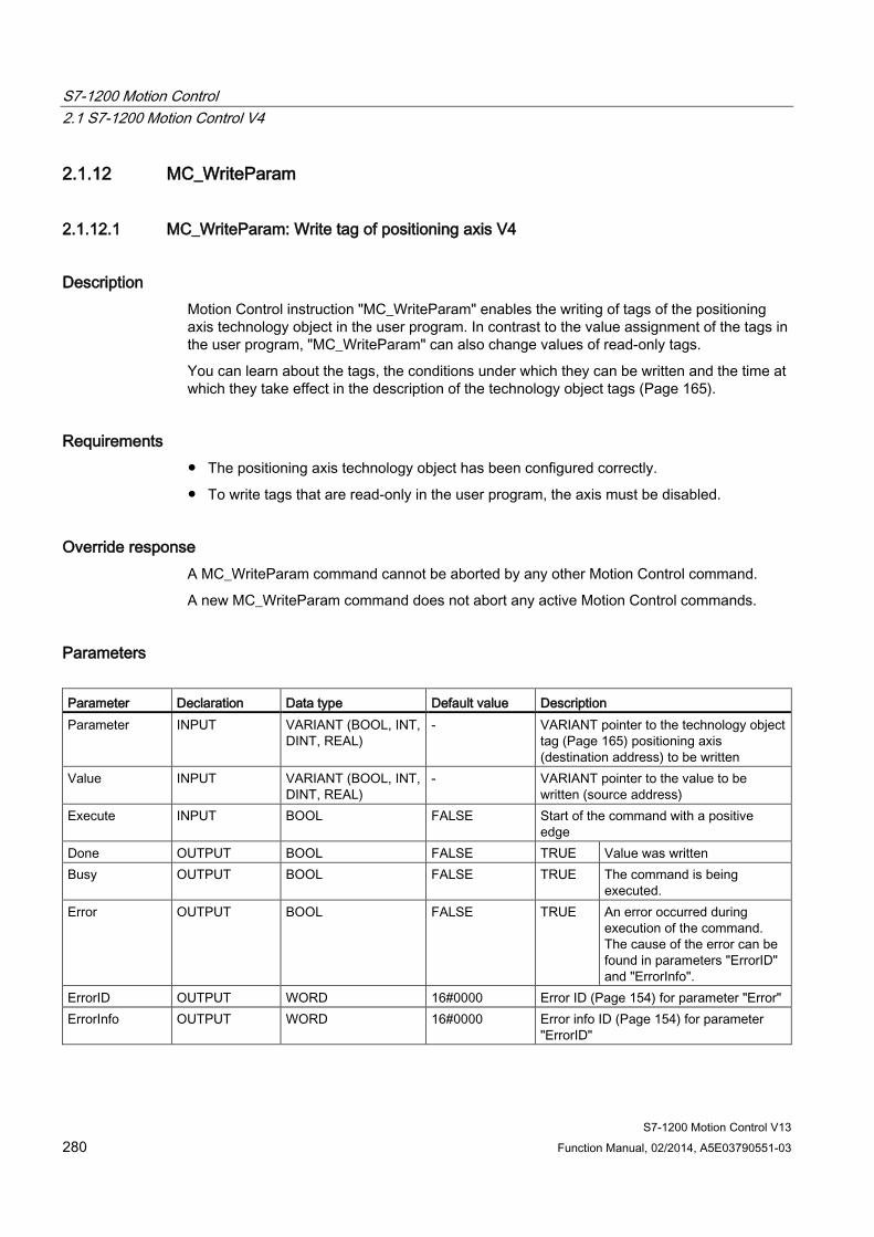
S7-1200 Motion Control 2.1 S7-1200 Motion Control V4
S7-1200 Motion Control V13 280 Function Manual, 02/2014, A5E03790551-03
2.1.12 MC_WriteParam
2.1.12.1 MC_WriteParam: Write tag of positioning axis V4
Description Motion Control instruction "MC_WriteParam" enables the writing of tags of the positioning axis technology object in the user program. In contrast to the value assignment of the tags in the user program, "MC_WriteParam" can also change values of read-only tags.
You can learn about the tags, the conditions under which they can be written and the time at which they take effect in the description of the technology object tags (Page 165).
Requirements ● The positioning axis technology object has been configured correctly.
● To write tags that are read-only in the user program, the axis must be disabled.
Override response A MC_WriteParam command cannot be aborted by any other Motion Control command.
A new MC_WriteParam command does not abort any active Motion Control commands.
Parameters Parameter Declaration Data type Default value Description Parameter INPUT VARIANT (BOOL, INT,
DINT, REAL) - VARIANT pointer to the technology object
tag (Page 165) positioning axis (destination address) to be written
Value INPUT VARIANT (BOOL, INT, DINT, REAL)
- VARIANT pointer to the value to be written (source address)
Execute INPUT BOOL FALSE Start of the command with a positive edge
Done OUTPUT BOOL FALSE TRUE Value was written Busy OUTPUT BOOL FALSE TRUE The command is being
executed. Error OUTPUT BOOL FALSE TRUE An error occurred during
execution of the command. The cause of the error can be found in parameters "ErrorID" and "ErrorInfo".
ErrorID OUTPUT WORD 16#0000 Error ID (Page 154) for parameter "Error" ErrorInfo OUTPUT WORD 16#0000 Error info ID (Page 154) for parameter
"ErrorID"
S7-1200 Motion Control 2.1 S7-1200 Motion Control V4
S7-1200 Motion Control V13 Function Manual, 02/2014, A5E03790551-03 281
See also Overview of the Motion Control statements (Page 114)
List of ErrorIDs and ErrorInfos (technology objects as of V4) (Page 154)
Tags of the positioning axis technology object as of V4 (Page 165)
S7-1200 Motion Control V1...3 (Page 282)
MC_Power: Enable, disable axis V4 (Page 242)
MC_Reset: Acknowledge fault V4 (Page 247)
MC_Home: Home axes, set reference point V4 (Page 249)
MC_Halt: Halt axes V4 (Page 253)
MC_MoveAbsolute: Absolute positioning of axes V4 (Page 256)
MC_MoveRelative: Relative positioning of axes V4 (Page 260)
MC_MoveVelocity: Move axes at preset rotational speed V4 (Page 264)
MC_MoveJog: Move axes in jog mode V4 (Page 268)
MC_CommandTable: Run axis commands as motion sequence V4 (Page 272)
MC_ChangeDynamic: Change dynamic settings of axis V4 (Page 275)
MC_ReadParam: Continuously read motion data of a positioning axis V4 (Page 278)
S7-1200 Motion Control 2.2 S7-1200 Motion Control V1...3
S7-1200 Motion Control V13 282 Function Manual, 02/2014, A5E03790551-03
2.2 S7-1200 Motion Control V1...3
2.2.1 MC_Power
2.2.1.1 MC_Power: Enable, disable axis V1...3
Description The Motion Control instruction "MC_Power" enables or disables an axis.
Requirements ● The axis technology object has been configured correctly.
● There is no pending enable-inhibiting error.
Override response Execution of "MC_Power" cannot be aborted by a Motion Control command.
Disabling the axis (input parameter "Enable" = FALSE) aborts all Motion Control commands for the associated technology object in accordance with the selected "StopMode".
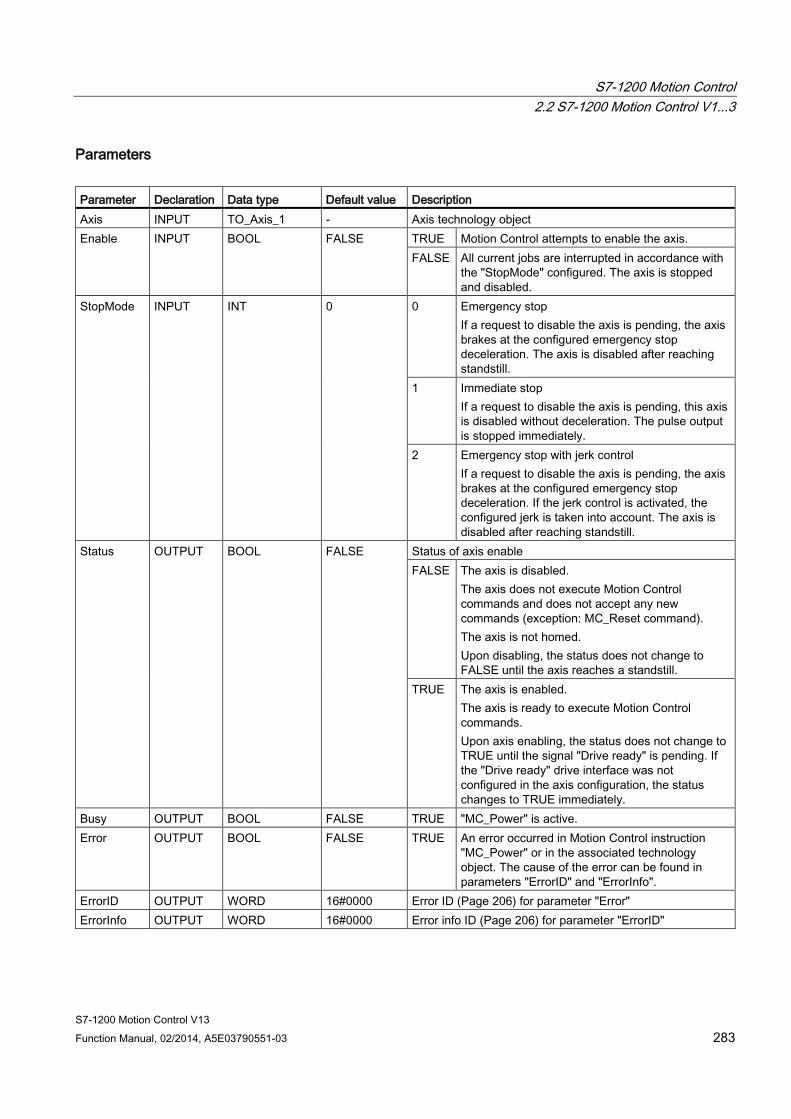
S7-1200 Motion Control 2.2 S7-1200 Motion Control V1...3
S7-1200 Motion Control V13 Function Manual, 02/2014, A5E03790551-03 283
Parameters Parameter Declaration Data type Default value Description Axis INPUT TO_Axis_1 - Axis technology object Enable INPUT BOOL FALSE TRUE Motion Control attempts to enable the axis.
FALSE All current jobs are interrupted in accordance with the "StopMode" configured. The axis is stopped and disabled.
StopMode INPUT INT 0 0 Emergency stop If a request to disable the axis is pending, the axis brakes at the configured emergency stop deceleration. The axis is disabled after reaching standstill.
1 Immediate stop If a request to disable the axis is pending, this axis is disabled without deceleration. The pulse output is stopped immediately.
2 Emergency stop with jerk control If a request to disable the axis is pending, the axis brakes at the configured emergency stop deceleration. If the jerk control is activated, the configured jerk is taken into account. The axis is disabled after reaching standstill.
Status OUTPUT BOOL FALSE Status of axis enable FALSE The axis is disabled.
The axis does not execute Motion Control commands and does not accept any new commands (exception: MC_Reset command). The axis is not homed. Upon disabling, the status does not change to FALSE until the axis reaches a standstill.
TRUE The axis is enabled. The axis is ready to execute Motion Control commands. Upon axis enabling, the status does not change to TRUE until the signal "Drive ready" is pending. If the "Drive ready" drive interface was not configured in the axis configuration, the status changes to TRUE immediately.
Busy OUTPUT BOOL FALSE TRUE "MC_Power" is active. Error OUTPUT BOOL FALSE TRUE An error occurred in Motion Control instruction
"MC_Power" or in the associated technology object. The cause of the error can be found in parameters "ErrorID" and "ErrorInfo".
ErrorID OUTPUT WORD 16#0000 Error ID (Page 206) for parameter "Error" ErrorInfo OUTPUT WORD 16#0000 Error info ID (Page 206) for parameter "ErrorID"
S7-1200 Motion Control 2.2 S7-1200 Motion Control V1...3
S7-1200 Motion Control V13 284 Function Manual, 02/2014, A5E03790551-03
Note
If the axis is switched off due to an error, it will be enabled again automatically after the error has been eliminated and acknowledged. This requires that the input parameter "Enable" has retained the value TRUE during this process.
Enabling an axis with configured drive interface To enable the axis, follow these steps:
1. Check the requirements indicated above.
2. Initialize input parameter "StopMode" with the desired value. Set the input parameter "Enable" to TRUE.
The enable output for "Drive enabled" changes to TRUE to enable the power to the drive. The CPU waits for the "Drive ready" signal of the drive.
When the "Drive ready" signal is available at the configured Ready input of the CPU, the axis is enabled. The output parameter "Status" and the tag of the technology object <Axis name>.StatusBits.Enable indicate the value TRUE.
Enabling an axis without configured drive interface To enable the axis, follow these steps:
1. Check the requirements indicated above.
2. Initialize input parameter "StopMode" with the desired value. Set the input parameter "Enable" to TRUE. The axis is enabled. The output parameter "Status" and the tag of the technology object <Axis name>.StatusBits.Enable indicate the value TRUE.
Disabling an axis To disable an axis, you can follow the steps described below:
1. Bring the axis to a standstill.
You can identify when the axis is at a standstill in the tag of the technology object <Axis name>.StatusBits.StandStill.
2. Set input parameter "Enable" to FALSE after standstill is reached.
3. If output parameters "Busy" and "Status" and the tag of technology object <Axis name>.StatusBits.Enable indicate the value FALSE, disabling of the axis is complete.
S7-1200 Motion Control 2.2 S7-1200 Motion Control V1...3
S7-1200 Motion Control V13 Function Manual, 02/2014, A5E03790551-03 285
See also Overview of the Motion Control statements (Page 114)
S7-1200 Motion Control V4 (Page 242)
ErrorIDs and ErrorInfos (Page 206)
MC_Power: Function chart V1...3 (Page 286)
MC_Reset: Acknowledge fault V1...3 (Page 287)
MC_Home: Home axes, set reference point V1...3 (Page 289)
MC_Halt: Halt axes V1...3 (Page 293)
MC_MoveAbsolute: Absolute positioning of axes V1...3 (Page 296)
MC_MoveRelative: Relative positioning of axes V1...3 (Page 299)
MC_MoveVelocity: Move axes at preset rotational speed V1...3 (Page 304)
MC_MoveJog: Move axes in jog mode V1...3 (Page 308)
MC_CommandTable: Run axis commands as motion sequence V2...3 (Page 311)
MC_ChangeDynamic: Change dynamic settings of axis V2...3 (Page 313)
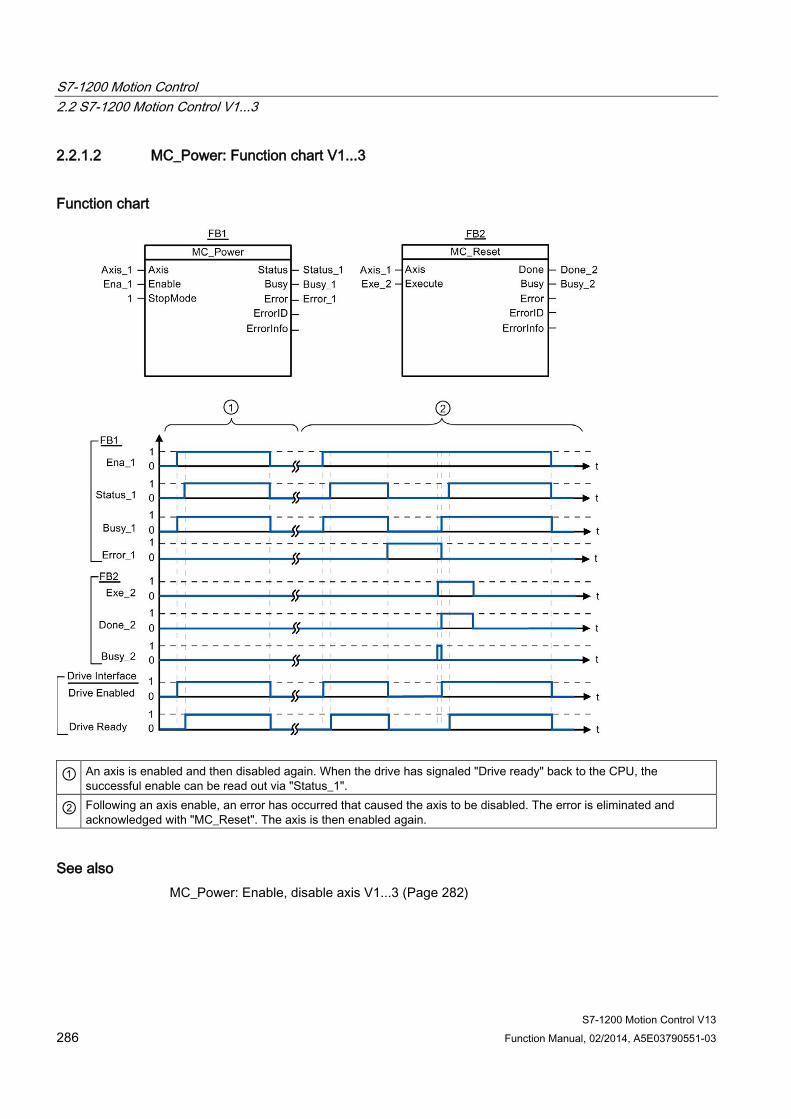
S7-1200 Motion Control 2.2 S7-1200 Motion Control V1...3
S7-1200 Motion Control V13 286 Function Manual, 02/2014, A5E03790551-03
2.2.1.2 MC_Power: Function chart V1...3
Function chart
① An axis is enabled and then disabled again. When the drive has signaled "Drive ready" back to the CPU, the successful enable can be read out via "Status_1".
② Following an axis enable, an error has occurred that caused the axis to be disabled. The error is eliminated and acknowledged with "MC_Reset". The axis is then enabled again.
See also MC_Power: Enable, disable axis V1...3 (Page 282)

S7-1200 Motion Control 2.2 S7-1200 Motion Control V1...3
S7-1200 Motion Control V13 Function Manual, 02/2014, A5E03790551-03 287
2.2.2 MC_Reset
2.2.2.1 MC_Reset: Acknowledge fault V1...3
Description Motion Control instruction "MC_Reset" can be used to acknowledge "Operating error with axis stop" and "Configuration error". The errors that require acknowledgement can be found in the "List of ErrorIDs and ErrorInfos" under "Remedy".
From version V3.0, the axis configuration can be downloaded to the work memory in RUN operating mode.
Requirements ● The axis technology object has been configured correctly.
● The cause of a pending configuration error requiring acknowledgement has been eliminated (for example, acceleration in positioning axis technology object has been changed to a valid value).
Override response The MC_Reset command cannot be aborted by any other Motion Control command.
The new MC_Reset command does not abort any other active Motion Control commands.
Parameters Parameter Declaration Data type Default value Description Axis INPUT TO_Axis_1 - Axis technology object Execute INPUT BOOL FALSE Start of the command with a positive edge Restart INPUT BOOL FALSE (From version V3.0)
TRUE Download the axis configuration from the load memory to the work memory. The command can only be executed when the axis is disabled. Refer to the notes on Download to the CPU (Page 86).
FALSE Acknowledges pending errors Done OUTPUT BOOL FALSE TRUE Error has been acknowledged. Busy OUTPUT BOOL FALSE TRUE The command is being executed. Error OUTPUT BOOL FALSE TRUE An error occurred during execution of the
command. The cause of the error can be found in parameters "ErrorID" and "ErrorInfo".
ErrorID OUTPUT WORD 16#0000 Error ID (Page 206) for parameter "Error" ErrorInfo OUTPUT WORD 16#0000 Error info ID (Page 206) for parameter "ErrorID"
S7-1200 Motion Control 2.2 S7-1200 Motion Control V1...3
S7-1200 Motion Control V13 288 Function Manual, 02/2014, A5E03790551-03
Acknowledging an error requiring acknowledgement with MC_Reset To acknowledge an error, follow these steps:
1. Check the requirements indicated above.
2. Start the acknowledgement of the error with a rising edge at input parameter "Execute".
3. If output parameter "Done" indicates the value TRUE and tag of technology object <Axis name>.StatusBits.Error the value FALSE, the error has been acknowledged.
See also Overview of the Motion Control statements (Page 114)
S7-1200 Motion Control V4 (Page 242)
ErrorIDs and ErrorInfos (Page 206)
Download to CPU (Page 86)
MC_Power: Enable, disable axis V1...3 (Page 282)
MC_Home: Home axes, set reference point V1...3 (Page 289)
MC_Halt: Halt axes V1...3 (Page 293)
MC_MoveAbsolute: Absolute positioning of axes V1...3 (Page 296)
MC_MoveRelative: Relative positioning of axes V1...3 (Page 299)
MC_MoveVelocity: Move axes at preset rotational speed V1...3 (Page 304)
MC_MoveJog: Move axes in jog mode V1...3 (Page 308)
MC_CommandTable: Run axis commands as motion sequence V2...3 (Page 311)
MC_ChangeDynamic: Change dynamic settings of axis V2...3 (Page 313)

S7-1200 Motion Control 2.2 S7-1200 Motion Control V1...3
S7-1200 Motion Control V13 Function Manual, 02/2014, A5E03790551-03 289
2.2.3 MC_Home
2.2.3.1 MC_Home: Home axes, set reference point V1...3
Description Motion Control instruction "MC_Home" is used to match the axis coordinates to the real, physical drive position. Homing is required for absolute positioning of the axis. The following types of homing can be executed:
● Active homing (Mode = 3)
The homing procedure is executed automatically.
● Passive homing (Mode = 2)
During passive homing, the "MC_Home" Motion Control instruction does not carry out any homing motion. The traversing motion required for this must be implemented by the user via other Motion Control instructions. When the homing switch is detected, the axis is homed.
● Direct homing absolute (Mode = 0)
The current axis position is set to the value of parameter "Position".
● Direct homing relative (Mode = 1)
The current axis position is offset by the value of parameter "Position".
Requirements ● The axis technology object has been configured correctly.
● The axis is enabled.
● No MC_CommandTable command may be active upon start with Mode = 0, 1, or 2.

S7-1200 Motion Control 2.2 S7-1200 Motion Control V1...3
S7-1200 Motion Control V13 290 Function Manual, 02/2014, A5E03790551-03
Override response The override response depends on the selected mode:
Mode = 0, 1
The MC_Home command cannot be aborted by any other Motion Control command.
The MC_Home command does not abort any active Motion Control commands. Position-related motion commands are resumed after homing according to the new homing position (value at input parameter: "Position").
Mode = 2
The MC_Home command can be aborted by the following Motion Control commands:
● MC_Home command Mode = 2, 3
The new MC_Home command aborts the following active Motion Control command:
● MC_Home command Mode = 2
Position-related motion commands are resumed after homing according to the new homing position (value at input parameter: "Position").
Mode = 3
The MC_Home command can be aborted by the following Motion Control commands:
● MC_Home command Mode = 3
● MC_Halt command
● MC_MoveAbsolute command
● MC_MoveRelative command
● MC_MoveVelocity command
● MC_MoveJog command
● MC_CommandTable command
The new MC_Home command aborts the following active Motion Control commands:
● MC_Home command Mode = 2, 3
● MC_Halt command
● MC_MoveAbsolute command
● MC_MoveRelative command
● MC_MoveVelocity command
● MC_MoveJog command
● MC_CommandTable command

S7-1200 Motion Control 2.2 S7-1200 Motion Control V1...3
S7-1200 Motion Control V13 Function Manual, 02/2014, A5E03790551-03 291
Parameters Parameter Declaration Data type Default value Description Axis INPUT TO_Axis_1 - Axis technology object Execute INPUT BOOL FALSE Start of the command with a positive edge Position INPUT REAL 0.0 • Mode = 0, 2, and 3
Absolute position of axis after completion of the homing operation
• Mode = 1
Correction value for the current axis position Limit values: -1.0e12 ≤ Position ≤ 1.0e12
Mode INPUT INT 0 Homing mode 0 Direct homing absolute
New axis position is the position value of parameter "Position".
1 Direct homing relative New axis position is the current axis position + position value of parameter "Position".
2 Passive homing Homing according to the axis configuration. Following homing, the value of parameter "Position" is set as the new axis position.
3 Active homing Homing procedure in accordance with the axis configuration. Following homing, the value of parameter "Position" is set as the new axis position.
Done OUTPUT BOOL FALSE TRUE Command completed Busy OUTPUT BOOL FALSE TRUE The command is being executed. CommandAborted OUTPUT BOOL FALSE TRUE During execution the command was
aborted by another command. Error OUTPUT BOOL FALSE TRUE An error occurred during execution of the
command. The cause of the error can be found in parameters "ErrorID" and "ErrorInfo".
ErrorID OUTPUT WORD 16#0000 Error ID (Page 206) for parameter "Error" ErrorInfo OUTPUT WORD 16#0000 Error info ID (Page 206) for parameter "ErrorID"
S7-1200 Motion Control 2.2 S7-1200 Motion Control V1...3
S7-1200 Motion Control V13 292 Function Manual, 02/2014, A5E03790551-03
Note
Axis homing is lost under the following conditions: • Disabling of axis by the "MC_Power" Motion Control instruction • Changeover between automatic mode and manual control • Upon start of active homing. After successful completion of the homing operation, axis
homing is again available. • After POWER OFF -> POWER ON of the CPU • After CPU restart (RUN-STOP -> STOP-RUN)
Homing an axis To home the axis, follow these stops:
1. Check the requirements indicated above.
2. Initialize the necessary input parameters with values, and start the homing operation with a rising edge at input parameter "Execute"
3. If output parameter "Done" and technology object tag <Axis name>.StatusBits.HomingDone indicate the value TRUE, homing is complete.
See also Overview of the Motion Control statements (Page 114)
S7-1200 Motion Control V4 (Page 242)
ErrorIDs and ErrorInfos (Page 206)
MC_Power: Enable, disable axis V1...3 (Page 282)
MC_Reset: Acknowledge fault V1...3 (Page 287)
MC_Halt: Halt axes V1...3 (Page 293)
MC_MoveAbsolute: Absolute positioning of axes V1...3 (Page 296)
MC_MoveRelative: Relative positioning of axes V1...3 (Page 299)
MC_MoveVelocity: Move axes at preset rotational speed V1...3 (Page 304)
MC_MoveJog: Move axes in jog mode V1...3 (Page 308)
MC_CommandTable: Run axis commands as motion sequence V2...3 (Page 311)
MC_ChangeDynamic: Change dynamic settings of axis V2...3 (Page 313)
S7-1200 Motion Control 2.2 S7-1200 Motion Control V1...3
S7-1200 Motion Control V13 Function Manual, 02/2014, A5E03790551-03 293
2.2.4 MC_Halt
2.2.4.1 MC_Halt: Halt axes V1...3
Description The "MC_Halt" Motion Control instruction stops all movements and brings the axis to a standstill with the configured deceleration. The standstill position is not defined.
Requirements ● The axis technology object has been configured correctly.
● The axis is enabled.
Override response The MC_Halt command can be aborted by the following Motion Control commands:
● MC_Home command Mode = 3
● MC_Halt command
● MC_MoveAbsolute command
● MC_MoveRelative command
● MC_MoveVelocity command
● MC_MoveJog command
● MC_CommandTable command
The new MC_Halt command aborts the following active Motion Control commands:
● MC_Home command Mode = 3
● MC_Halt command
● MC_MoveAbsolute command
● MC_MoveRelative command
● MC_MoveVelocity command
● MC_MoveJog command
● MC_CommandTable command
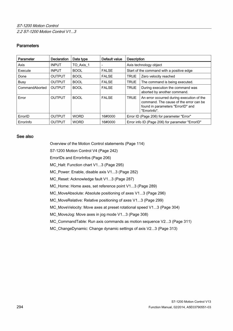
S7-1200 Motion Control 2.2 S7-1200 Motion Control V1...3
S7-1200 Motion Control V13 294 Function Manual, 02/2014, A5E03790551-03
Parameters Parameter Declaration Data type Default value Description Axis INPUT TO_Axis_1 - Axis technology object Execute INPUT BOOL FALSE Start of the command with a positive edge Done OUTPUT BOOL FALSE TRUE Zero velocity reached Busy OUTPUT BOOL FALSE TRUE The command is being executed. CommandAborted OUTPUT BOOL FALSE TRUE During execution the command was
aborted by another command. Error OUTPUT BOOL FALSE TRUE An error occurred during execution of the
command. The cause of the error can be found in parameters "ErrorID" and "ErrorInfo".
ErrorID OUTPUT WORD 16#0000 Error ID (Page 206) for parameter "Error" ErrorInfo OUTPUT WORD 16#0000 Error info ID (Page 206) for parameter "ErrorID"
See also Overview of the Motion Control statements (Page 114)
S7-1200 Motion Control V4 (Page 242)
ErrorIDs and ErrorInfos (Page 206)
MC_Halt: Function chart V1...3 (Page 295)
MC_Power: Enable, disable axis V1...3 (Page 282)
MC_Reset: Acknowledge fault V1...3 (Page 287)
MC_Home: Home axes, set reference point V1...3 (Page 289)
MC_MoveAbsolute: Absolute positioning of axes V1...3 (Page 296)
MC_MoveRelative: Relative positioning of axes V1...3 (Page 299)
MC_MoveVelocity: Move axes at preset rotational speed V1...3 (Page 304)
MC_MoveJog: Move axes in jog mode V1...3 (Page 308)
MC_CommandTable: Run axis commands as motion sequence V2...3 (Page 311)
MC_ChangeDynamic: Change dynamic settings of axis V2...3 (Page 313)
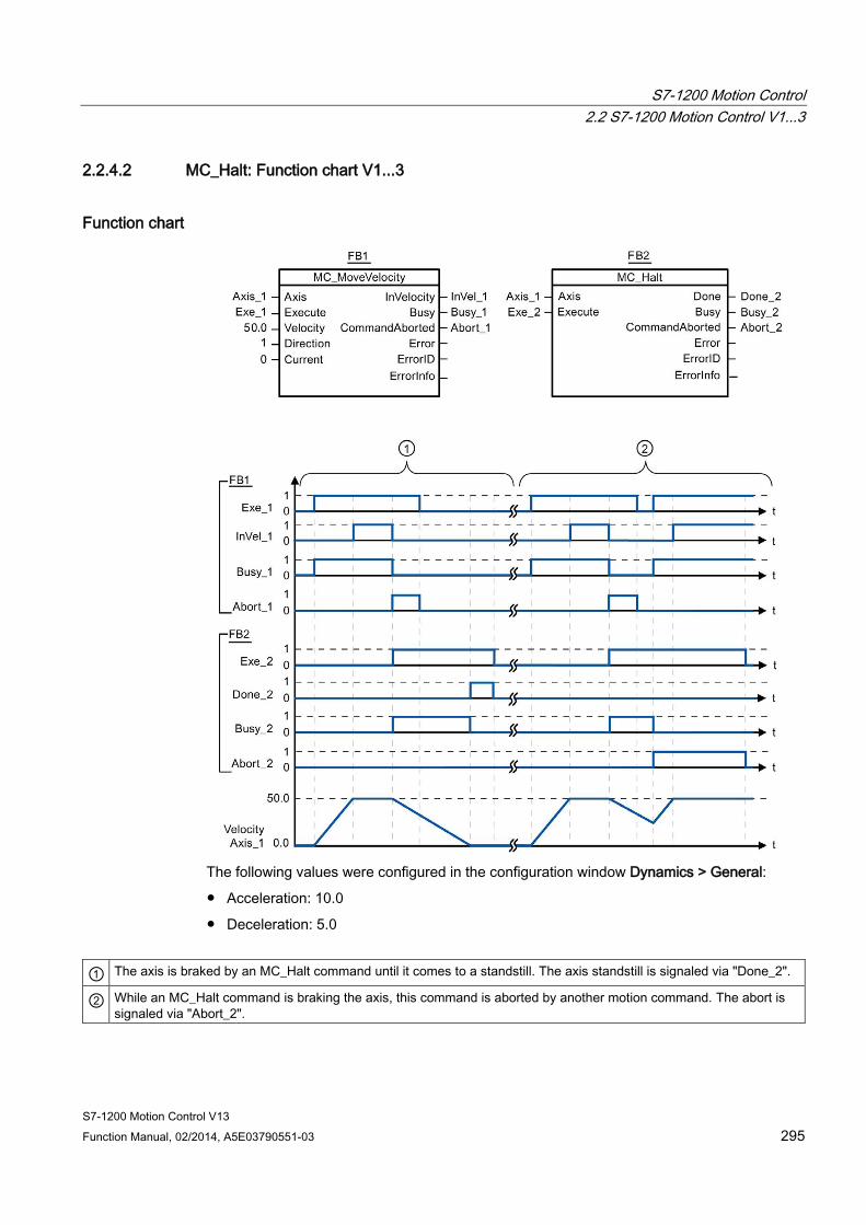
S7-1200 Motion Control 2.2 S7-1200 Motion Control V1...3
S7-1200 Motion Control V13 Function Manual, 02/2014, A5E03790551-03 295
2.2.4.2 MC_Halt: Function chart V1...3
Function chart
The following values were configured in the configuration window Dynamics > General:
● Acceleration: 10.0
● Deceleration: 5.0
① The axis is braked by an MC_Halt command until it comes to a standstill. The axis standstill is signaled via "Done_2".
② While an MC_Halt command is braking the axis, this command is aborted by another motion command. The abort is signaled via "Abort_2".
S7-1200 Motion Control 2.2 S7-1200 Motion Control V1...3
S7-1200 Motion Control V13 296 Function Manual, 02/2014, A5E03790551-03
See also MC_Halt: Halt axes V1...3 (Page 293)
2.2.5 MC_MoveAbsolute
2.2.5.1 MC_MoveAbsolute: Absolute positioning of axes V1...3
Description The "MC_MoveAbsolute" Motion Control instruction starts an axis positioning motion to move it to an absolute position.
Requirements ● The axis technology object has been configured correctly.
● The axis is enabled.
● The axis is homed.
Override response The MC_MoveAbsolute command can be aborted by the following Motion Control commands:
● MC_Home command Mode = 3
● MC_Halt command
● MC_MoveAbsolute command
● MC_MoveRelative command
● MC_MoveVelocity command
● MC_MoveJog command
● MC_CommandTable command
The new MC_MoveAbsolute command aborts the following active Motion Control commands:
● MC_Home command Mode = 3
● MC_Halt command
● MC_MoveAbsolute command
● MC_MoveRelative command
● MC_MoveVelocity command
● MC_MoveJog command
● MC_CommandTable command
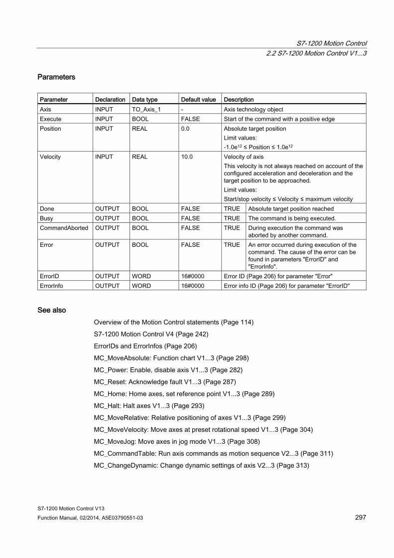
S7-1200 Motion Control 2.2 S7-1200 Motion Control V1...3
S7-1200 Motion Control V13 Function Manual, 02/2014, A5E03790551-03 297
Parameters Parameter Declaration Data type Default value Description Axis INPUT TO_Axis_1 - Axis technology object Execute INPUT BOOL FALSE Start of the command with a positive edge Position INPUT REAL 0.0 Absolute target position
Limit values: -1.0e12 ≤ Position ≤ 1.0e12
Velocity INPUT REAL 10.0 Velocity of axis This velocity is not always reached on account of the configured acceleration and deceleration and the target position to be approached. Limit values: Start/stop velocity ≤ Velocity ≤ maximum velocity
Done OUTPUT BOOL FALSE TRUE Absolute target position reached Busy OUTPUT BOOL FALSE TRUE The command is being executed. CommandAborted OUTPUT BOOL FALSE TRUE During execution the command was
aborted by another command. Error OUTPUT BOOL FALSE TRUE An error occurred during execution of the
command. The cause of the error can be found in parameters "ErrorID" and "ErrorInfo".
ErrorID OUTPUT WORD 16#0000 Error ID (Page 206) for parameter "Error" ErrorInfo OUTPUT WORD 16#0000 Error info ID (Page 206) for parameter "ErrorID"
See also Overview of the Motion Control statements (Page 114)
S7-1200 Motion Control V4 (Page 242)
ErrorIDs and ErrorInfos (Page 206)
MC_MoveAbsolute: Function chart V1...3 (Page 298)
MC_Power: Enable, disable axis V1...3 (Page 282)
MC_Reset: Acknowledge fault V1...3 (Page 287)
MC_Home: Home axes, set reference point V1...3 (Page 289)
MC_Halt: Halt axes V1...3 (Page 293)
MC_MoveRelative: Relative positioning of axes V1...3 (Page 299)
MC_MoveVelocity: Move axes at preset rotational speed V1...3 (Page 304)
MC_MoveJog: Move axes in jog mode V1...3 (Page 308)
MC_CommandTable: Run axis commands as motion sequence V2...3 (Page 311)
MC_ChangeDynamic: Change dynamic settings of axis V2...3 (Page 313)

S7-1200 Motion Control 2.2 S7-1200 Motion Control V1...3
S7-1200 Motion Control V13 298 Function Manual, 02/2014, A5E03790551-03
2.2.5.2 MC_MoveAbsolute: Function chart V1...3
Function chart
The following values were configured in the configuration window Dynamics > General:
● Acceleration: 10.0
● Deceleration: 10.0

S7-1200 Motion Control 2.2 S7-1200 Motion Control V1...3
S7-1200 Motion Control V13 Function Manual, 02/2014, A5E03790551-03 299
① An axis is moved to absolute position 1000.0 with an MC_MoveAbsolute command. When the axis reaches the target position, this is signaled via "Done_1". When "Done_1" = TRUE, another MC_MoveAbsolute command, with target position 1500.0, is started. Because of the response times (e.g., cycle time of user program, etc.), the axis comes to a standstill briefly (see zoomed-in detail). When the axis reaches the new target position, this is signaled via "Done_2".
② An active MC_MoveAbsolute command is aborted by another MC_MoveAbsolute command. The abort is signaled via "Abort_1". The axis is then moved at the new velocity to the new target position 1500.0. When the new target position is reached, this is signaled via "Done_2".
See also MC_MoveAbsolute: Absolute positioning of axes V1...3 (Page 296)

S7-1200 Motion Control 2.2 S7-1200 Motion Control V1...3
S7-1200 Motion Control V13 300 Function Manual, 02/2014, A5E03790551-03
2.2.6 MC_MoveRelative
2.2.6.1 MC_MoveRelative: Relative positioning of axes V1...3
Description The "MC_MoveRelative" Motion Control instruction starts a positioning motion relative to the start position.
Requirements ● The axis technology object has been configured correctly.
● The axis is enabled.
Override response The MC_MoveRelative command can be aborted by the following Motion Control commands:
● MC_Home command Mode = 3
● MC_Halt command
● MC_MoveAbsolute command
● MC_MoveRelative command
● MC_MoveVelocity command
● MC_MoveJog command
● MC_CommandTable command
The new MC_MoveRelative command aborts the following active Motion Control commands:
● MC_Home command Mode = 3
● MC_Halt command
● MC_MoveAbsolute command
● MC_MoveRelative command
● MC_MoveVelocity command
● MC_MoveJog command
● MC_CommandTable command

S7-1200 Motion Control 2.2 S7-1200 Motion Control V1...3
S7-1200 Motion Control V13 Function Manual, 02/2014, A5E03790551-03 301
Parameters Parameter Declaration Data type Default value Description Axis INPUT TO_Axis_1 - Axis technology object Execute INPUT BOOL FALSE Start of the command with a positive edge Distance INPUT REAL 0.0 Travel distance for the positioning operation
Limit values: -1.0e12 ≤ Distance ≤ 1.0e12
Velocity INPUT REAL 10.0 Velocity of axis This velocity is not always reached on account of the configured acceleration and deceleration and the distance to be traveled. Limit values: Start/stop velocity ≤ Velocity ≤ maximum velocity
Done OUTPUT BOOL FALSE TRUE Target position reached Busy OUTPUT BOOL FALSE TRUE The command is being executed. CommandAborted OUTPUT BOOL FALSE TRUE During execution the command was
aborted by another command. Error OUTPUT BOOL FALSE TRUE An error occurred during execution of the
command. The cause of the error can be found in parameters "ErrorID" and "ErrorInfo".
ErrorID OUTPUT WORD 16#0000 Error ID (Page 206) for parameter "Error" ErrorInfo OUTPUT WORD 16#0000 Error info ID (Page 206) for parameter "ErrorID"
See also Overview of the Motion Control statements (Page 114)
S7-1200 Motion Control V4 (Page 242)
ErrorIDs and ErrorInfos (Page 206)
MC_MoveRelative: Function chart V1...3 (Page 302)
MC_Power: Enable, disable axis V1...3 (Page 282)
MC_Reset: Acknowledge fault V1...3 (Page 287)
MC_Home: Home axes, set reference point V1...3 (Page 289)
MC_Halt: Halt axes V1...3 (Page 293)
MC_MoveAbsolute: Absolute positioning of axes V1...3 (Page 296)
MC_MoveVelocity: Move axes at preset rotational speed V1...3 (Page 304)
MC_MoveJog: Move axes in jog mode V1...3 (Page 308)
MC_CommandTable: Run axis commands as motion sequence V2...3 (Page 311)
MC_ChangeDynamic: Change dynamic settings of axis V2...3 (Page 313)
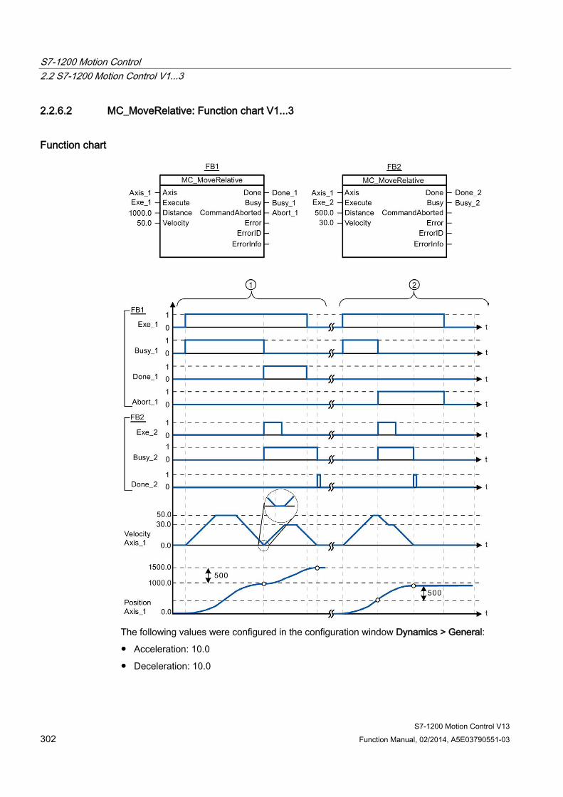
S7-1200 Motion Control 2.2 S7-1200 Motion Control V1...3
S7-1200 Motion Control V13 302 Function Manual, 02/2014, A5E03790551-03
2.2.6.2 MC_MoveRelative: Function chart V1...3
Function chart
The following values were configured in the configuration window Dynamics > General:
● Acceleration: 10.0
● Deceleration: 10.0
S7-1200 Motion Control 2.2 S7-1200 Motion Control V1...3
S7-1200 Motion Control V13 Function Manual, 02/2014, A5E03790551-03 303
① The axis is moved by an MC_MoveRelative command by the distance ("Distance") 1000.0. When the axis reaches the target position, this is signaled via "Done_1". When "Done_1" = TRUE, another MC_MoveRelative command, with travel distance 500.0, is started. Because of the response times (e.g., cycle time of user program, etc.), the axis comes to a standstill briefly (see zoomed-in detail). When the axis reaches the new target position, this is signaled via "Done_2".
② An active MC_MoveRelative command is aborted by another MC_MoveRelative command. The abort is signaled via "Abort_1". The axis is then moved at the new velocity by the new distance ("Distance") 500.0. When the new target position is reached, this is signaled via "Done_2".
See also MC_MoveRelative: Relative positioning of axes V1...3 (Page 299)
S7-1200 Motion Control 2.2 S7-1200 Motion Control V1...3
S7-1200 Motion Control V13 304 Function Manual, 02/2014, A5E03790551-03
2.2.7 MC_MoveVelocity
2.2.7.1 MC_MoveVelocity: Move axes at preset rotational speed V1...3
Description Motion control instruction "MC_MoveVelocity" moves the axis constantly at the specified velocity.
Requirements ● The axis technology object has been configured correctly.
● The axis is enabled.
Override response MC_MoveVelocity can be aborted by the following Motion Control commands:
● MC_Home command Mode = 3
● MC_Halt command
● MC_MoveAbsolute command
● MC_MoveRelative command
● MC_MoveVelocity command
● MC_MoveJog command
● MC_CommandTable command
The new MC_MoveVelocity command aborts the following active Motion Control commands:
● MC_Home command Mode = 3
● MC_Halt command
● MC_MoveAbsolute command
● MC_MoveRelative command
● MC_MoveVelocity command
● MC_MoveJog command
● MC_CommandTable command

S7-1200 Motion Control 2.2 S7-1200 Motion Control V1...3
S7-1200 Motion Control V13 Function Manual, 02/2014, A5E03790551-03 305
Parameters Parameter Declaration Data type Default value Description Axis INPUT TO_Axis_1 - Axis technology object Execute INPUT BOOL FALSE Start of the command with a positive edge Velocity INPUT REAL 10.0 Velocity specification for axis motion
Limit values: Start/stop velocity ≤ |Velocity ≤ maximum velocity (Velocity = 0.0 is permitted)
Direction INPUT INT 0 Direction specification 0 Direction of rotation corresponds to the sign
of the value in parameter "Velocity" 1 Positive direction of rotation
(The sign of the value in parameter "Velocity" is ignored)
2 Negative direction of rotation (The sign of the value in parameter "Velocity" is ignored)
Current INPUT BOOL FALSE Maintain current velocity FALSE "Maintain current velocity" is deactivated.
The values of parameters "Velocity" and "Direction" are used.
TRUE "Maintain current velocity" is activated. The values in parameters "Velocity" and "Direction" are not taken into account. When the axis resumes motion at the current velocity, the "InVelocity" parameter returns the value TRUE.
InVelocity OUTPUT BOOL FALSE TRUE • "Current" = FALSE:
The velocity specified in parameter "Velocity" was reached.
• "Current" = TRUE:
The axis travels at the current velocity at the start time.
Busy OUTPUT BOOL FALSE TRUE The command is being executed. CommandAborted OUTPUT BOOL FALSE TRUE During execution the command was
aborted by another command. Error OUTPUT BOOL FALSE TRUE An error occurred during execution of the
command. The cause of the error can be found in parameters "ErrorID" and "ErrorInfo".
ErrorID OUTPUT WORD 16#0000 Error ID (Page 206) for parameter "Error" ErrorInfo OUTPUT WORD 16#0000 Error info ID (Page 206) for parameter "ErrorID"
S7-1200 Motion Control 2.2 S7-1200 Motion Control V1...3
S7-1200 Motion Control V13 306 Function Manual, 02/2014, A5E03790551-03
Behavior with zero setpoint velocity (Velocity = 0.0) An MC_MoveVelocity command with "Velocity" = 0.0 (such as an MC_Halt command) aborts active motion commands and stops the axis with the configured deceleration.
When the axis comes to a standstill, output parameter "InVelocity" indicates TRUE for at least one program cycle.
"Busy" indicates the value TRUE during the deceleration process and changes to FALSE together with "InVelocity". If parameter "Execute" = TRUE is set, "InVelocity" and "Busy" are latched.
When the "MC_MoveVelocity" command is started, status bit "SpeedCommand" is set in the technology object. Status bit "ConstantVelocity" is set upon axis standstill. Both bits are adapted to the new situation when a new motion command is started.
See also Overview of the Motion Control statements (Page 114)
S7-1200 Motion Control V4 (Page 242)
ErrorIDs and ErrorInfos (Page 206)
MC_MoveVelocity: Function chart V1...3 (Page 307)
MC_Power: Enable, disable axis V1...3 (Page 282)
MC_Reset: Acknowledge fault V1...3 (Page 287)
MC_Home: Home axes, set reference point V1...3 (Page 289)
MC_Halt: Halt axes V1...3 (Page 293)
MC_MoveAbsolute: Absolute positioning of axes V1...3 (Page 296)
MC_MoveRelative: Relative positioning of axes V1...3 (Page 299)
MC_MoveJog: Move axes in jog mode V1...3 (Page 308)
MC_CommandTable: Run axis commands as motion sequence V2...3 (Page 311)
MC_ChangeDynamic: Change dynamic settings of axis V2...3 (Page 313)

S7-1200 Motion Control 2.2 S7-1200 Motion Control V1...3
S7-1200 Motion Control V13 Function Manual, 02/2014, A5E03790551-03 307
2.2.7.2 MC_MoveVelocity: Function chart V1...3
Function chart
The following values were configured in the configuration window Dynamics > General:
● Acceleration: 10.0
● Deceleration: 10.0
① An active MC_MoveVelocity command signals via "InVel_1" that its target velocity has been reached. It is then aborted by another MC_MoveVelocity command. The abort is signaled via "Abort_1". When the new target velocity 15.0 is reached, this is signaled via "InVel_2". The axis then continues moving at the new constant velocity.
② An active MC_MoveVelocity command is aborted by another MC_MoveVelocity command prior to reaching its target velocity. The abort is signaled via "Abort_1". When the new target velocity 15.0 is reached, this is signaled via "InVel_2". The axis then continues moving at the new constant velocity.
S7-1200 Motion Control 2.2 S7-1200 Motion Control V1...3
S7-1200 Motion Control V13 308 Function Manual, 02/2014, A5E03790551-03
See also MC_MoveVelocity: Move axes at preset rotational speed V1...3 (Page 304)
2.2.8 MC_MoveJog
2.2.8.1 MC_MoveJog: Move axes in jog mode V1...3
Description Motion control instruction "MC_MoveJog" moves the axis constantly at the specified velocity in jog mode. You use this Motion Control instruction, for example, for testing and commissioning purposes.
Requirements ● The axis technology object has been configured correctly.
● The axis is enabled.
Override response The MC_MoveJog command can be aborted by the following Motion Control commands:
● MC_Home command Mode = 3
● MC_Halt command
● MC_MoveAbsolute command
● MC_MoveRelative command
● MC_MoveVelocity command
● MC_MoveJog command
● MC_CommandTable command
The new MC_MoveJog command aborts the following active Motion Control commands:
● MC_Home command Mode = 3
● MC_Halt command
● MC_MoveAbsolute command
● MC_MoveRelative command
● MC_MoveVelocity command
● MC_MoveJog command
● MC_CommandTable command
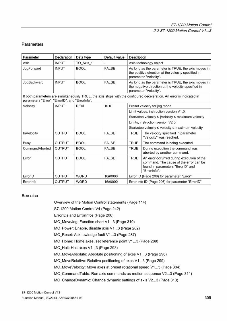
S7-1200 Motion Control 2.2 S7-1200 Motion Control V1...3
S7-1200 Motion Control V13 Function Manual, 02/2014, A5E03790551-03 309
Parameters Parameter Declaration Data type Default value Description Axis INPUT TO_Axis_1 - Axis technology object JogForward INPUT BOOL FALSE As long as the parameter is TRUE, the axis moves in
the positive direction at the velocity specified in parameter "Velocity".
JogBackward INPUT BOOL FALSE As long as the parameter is TRUE, the axis moves in the negative direction at the velocity specified in parameter "Velocity".
If both parameters are simultaneously TRUE, the axis stops with the configured deceleration. An error is indicated in parameters "Error", "ErrorID", and "ErrorInfo". Velocity INPUT REAL 10.0 Preset velocity for jog mode
Limit values, instruction version V1.0: Start/stop velocity ≤ |Velocity ≤ maximum velocity Limits, instruction version V2.0: Start/stop velocity ≤ velocity ≤ maximum velocity
InVelocity OUTPUT BOOL FALSE TRUE The velocity specified in parameter "Velocity" was reached.
Busy OUTPUT BOOL FALSE TRUE The command is being executed. CommandAborted OUTPUT BOOL FALSE TRUE During execution the command was
aborted by another command. Error OUTPUT BOOL FALSE TRUE An error occurred during execution of the
command. The cause of the error can be found in parameters "ErrorID" and "ErrorInfo".
ErrorID OUTPUT WORD 16#0000 Error ID (Page 206) for parameter "Error" ErrorInfo OUTPUT WORD 16#0000 Error info ID (Page 206) for parameter "ErrorID"
See also Overview of the Motion Control statements (Page 114) S7-1200 Motion Control V4 (Page 242) ErrorIDs and ErrorInfos (Page 206) MC_MoveJog: Function chart V1...3 (Page 310) MC_Power: Enable, disable axis V1...3 (Page 282) MC_Reset: Acknowledge fault V1...3 (Page 287) MC_Home: Home axes, set reference point V1...3 (Page 289) MC_Halt: Halt axes V1...3 (Page 293) MC_MoveAbsolute: Absolute positioning of axes V1...3 (Page 296) MC_MoveRelative: Relative positioning of axes V1...3 (Page 299) MC_MoveVelocity: Move axes at preset rotational speed V1...3 (Page 304) MC_CommandTable: Run axis commands as motion sequence V2...3 (Page 311) MC_ChangeDynamic: Change dynamic settings of axis V2...3 (Page 313)
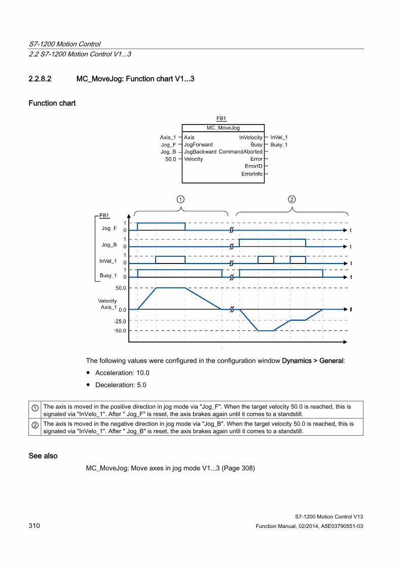
S7-1200 Motion Control 2.2 S7-1200 Motion Control V1...3
S7-1200 Motion Control V13 310 Function Manual, 02/2014, A5E03790551-03
2.2.8.2 MC_MoveJog: Function chart V1...3
Function chart
The following values were configured in the configuration window Dynamics > General:
● Acceleration: 10.0
● Deceleration: 5.0
① The axis is moved in the positive direction in jog mode via "Jog_F". When the target velocity 50.0 is reached, this is signaled via "InVelo_1". After " Jog_F" is reset, the axis brakes again until it comes to a standstill.
② The axis is moved in the negative direction in jog mode via "Jog_B". When the target velocity 50.0 is reached, this is signaled via "InVelo_1". After " Jog_B" is reset, the axis brakes again until it comes to a standstill.
See also MC_MoveJog: Move axes in jog mode V1...3 (Page 308)
S7-1200 Motion Control 2.2 S7-1200 Motion Control V1...3
S7-1200 Motion Control V13 Function Manual, 02/2014, A5E03790551-03 311
2.2.9 MC_CommandTable
2.2.9.1 MC_CommandTable: Run axis commands as motion sequence V2...3
Description The Motion Control instruction "MC_CommandTable" combines multiple individual axis control commands in one movement sequence.
Requirements ● The axis technology object has been inserted in V2 and correctly configured.
● The command table technology object has been inserted and correctly configured.
● The axis is enabled.
Override response The MC_CommandTable command can be aborted by the following Motion Control commands:
● MC_Home command Mode = 3
● MC_Halt command
● MC_MoveAbsolute command
● MC_MoveRelative command
● MC_MoveVelocity command
● MC_MoveJog command
● MC_CommandTable command
The new MC_CommandTable command aborts the following active Motion Control commands:
● MC_Home command Mode = 3
● MC_Halt command
● MC_MoveAbsolute command
● MC_MoveRelative command
● MC_MoveVelocity command
● MC_MoveJog command
● MC_CommandTable command
The active Motion Control command is cancelled by the start of the first "Positioning Relative", "Positioning Absolute", "Velocity set point" or "Halt" command.
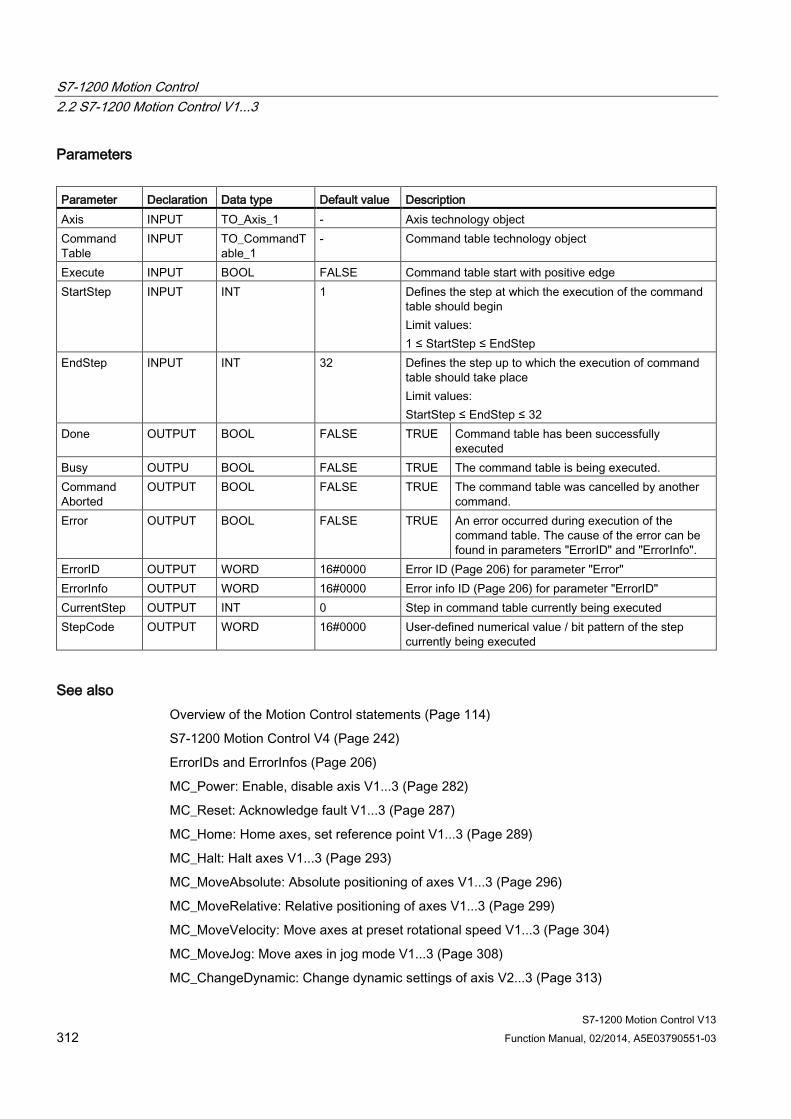
S7-1200 Motion Control 2.2 S7-1200 Motion Control V1...3
S7-1200 Motion Control V13 312 Function Manual, 02/2014, A5E03790551-03
Parameters Parameter Declaration Data type Default value Description Axis INPUT TO_Axis_1 - Axis technology object Command Table
INPUT TO_CommandTable_1
- Command table technology object
Execute INPUT BOOL FALSE Command table start with positive edge StartStep INPUT INT 1 Defines the step at which the execution of the command
table should begin Limit values: 1 ≤ StartStep ≤ EndStep
EndStep INPUT INT 32 Defines the step up to which the execution of command table should take place Limit values: StartStep ≤ EndStep ≤ 32
Done OUTPUT BOOL FALSE TRUE Command table has been successfully executed
Busy OUTPU BOOL FALSE TRUE The command table is being executed. Command Aborted
OUTPUT BOOL FALSE TRUE The command table was cancelled by another command.
Error OUTPUT BOOL FALSE TRUE An error occurred during execution of the command table. The cause of the error can be found in parameters "ErrorID" and "ErrorInfo".
ErrorID OUTPUT WORD 16#0000 Error ID (Page 206) for parameter "Error" ErrorInfo OUTPUT WORD 16#0000 Error info ID (Page 206) for parameter "ErrorID" CurrentStep OUTPUT INT 0 Step in command table currently being executed StepCode OUTPUT WORD 16#0000 User-defined numerical value / bit pattern of the step
currently being executed
See also Overview of the Motion Control statements (Page 114)
S7-1200 Motion Control V4 (Page 242)
ErrorIDs and ErrorInfos (Page 206)
MC_Power: Enable, disable axis V1...3 (Page 282)
MC_Reset: Acknowledge fault V1...3 (Page 287)
MC_Home: Home axes, set reference point V1...3 (Page 289)
MC_Halt: Halt axes V1...3 (Page 293)
MC_MoveAbsolute: Absolute positioning of axes V1...3 (Page 296)
MC_MoveRelative: Relative positioning of axes V1...3 (Page 299)
MC_MoveVelocity: Move axes at preset rotational speed V1...3 (Page 304)
MC_MoveJog: Move axes in jog mode V1...3 (Page 308)
MC_ChangeDynamic: Change dynamic settings of axis V2...3 (Page 313)
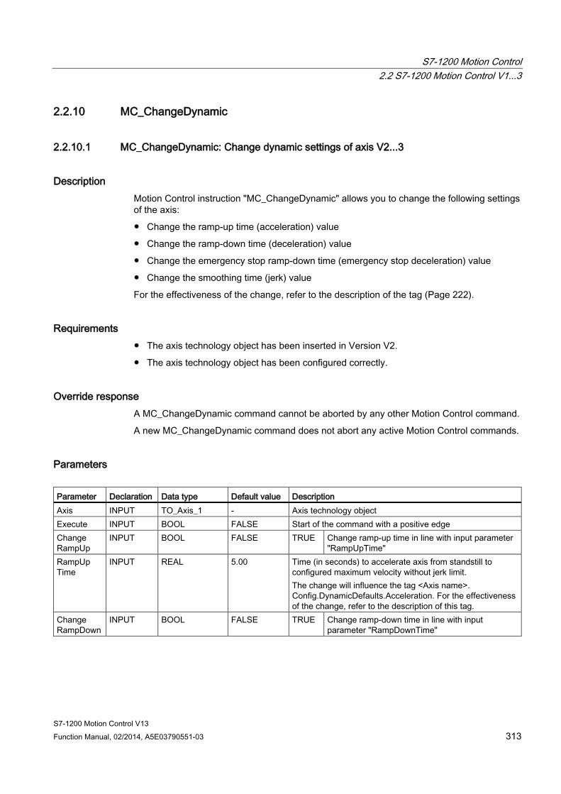
S7-1200 Motion Control 2.2 S7-1200 Motion Control V1...3
S7-1200 Motion Control V13 Function Manual, 02/2014, A5E03790551-03 313
2.2.10 MC_ChangeDynamic
2.2.10.1 MC_ChangeDynamic: Change dynamic settings of axis V2...3
Description Motion Control instruction "MC_ChangeDynamic" allows you to change the following settings of the axis:
● Change the ramp-up time (acceleration) value
● Change the ramp-down time (deceleration) value
● Change the emergency stop ramp-down time (emergency stop deceleration) value
● Change the smoothing time (jerk) value
For the effectiveness of the change, refer to the description of the tag (Page 222).
Requirements ● The axis technology object has been inserted in Version V2.
● The axis technology object has been configured correctly.
Override response A MC_ChangeDynamic command cannot be aborted by any other Motion Control command.
A new MC_ChangeDynamic command does not abort any active Motion Control commands.
Parameters Parameter Declaration Data type Default value Description Axis INPUT TO_Axis_1 - Axis technology object Execute INPUT BOOL FALSE Start of the command with a positive edge Change RampUp
INPUT BOOL FALSE TRUE Change ramp-up time in line with input parameter "RampUpTime"
RampUp Time
INPUT REAL 5.00 Time (in seconds) to accelerate axis from standstill to configured maximum velocity without jerk limit. The change will influence the tag <Axis name>. Config.DynamicDefaults.Acceleration. For the effectiveness of the change, refer to the description of this tag.
Change RampDown
INPUT BOOL FALSE TRUE Change ramp-down time in line with input parameter "RampDownTime"
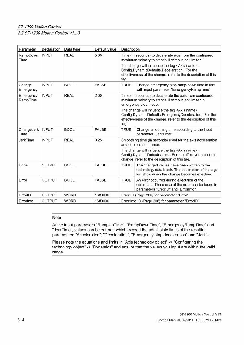
S7-1200 Motion Control 2.2 S7-1200 Motion Control V1...3
S7-1200 Motion Control V13 314 Function Manual, 02/2014, A5E03790551-03
Parameter Declaration Data type Default value Description RampDownTime
INPUT REAL 5.00 Time (in seconds) to decelerate axis from the configured maximum velocity to standstill without jerk limiter. The change will influence the tag <Axis name>. Config.DynamicDefaults.Deceleration . For the effectiveness of the change, refer to the description of this tag.
Change Emergency
INPUT BOOL FALSE TRUE Change emergency stop ramp-down time in line with input parameter "EmergencyRampTime"
EmergencyRampTime
INPUT REAL 2.00 Time (in seconds) to decelerate the axis from configured maximum velocity to standstill without jerk limiter in emergency stop mode. The change will influence the tag <Axis name>. Config.DynamicDefaults.EmergencyDeceleration . For the effectiveness of the change, refer to the description of this tag.
ChangeJerkTime
INPUT BOOL FALSE TRUE Change smoothing time according to the input parameter "JerkTime"
JerkTime INPUT REAL 0.25 Smoothing time (in seconds) used for the axis acceleration and deceleration ramps The change will influence the tag <Axis name>. Config.DynamicDefaults.Jerk . For the effectiveness of the change, refer to the description of this tag.
Done OUTPUT BOOL FALSE TRUE The changed values have been written to the technology data block. The description of the tags will show when the change becomes effective.
Error OUTPUT BOOL FALSE TRUE An error occurred during execution of the command. The cause of the error can be found in parameters "ErrorID" and "ErrorInfo".
ErrorID OUTPUT WORD 16#0000 Error ID (Page 206) for parameter "Error" ErrorInfo OUTPUT WORD 16#0000 Error info ID (Page 206) for parameter "ErrorID"
Note
At the input parameters "RampUpTime", "RampDownTime", "EmergencyRampTime" and "JerkTime", values can be entered which exceed the admissible limits of the resulting parameters: "Acceleration", "Deceleration", "Emergency stop deceleration" and "Jerk".
Please note the equations and limits in "Axis technology object" -> "Configuring the technology object" -> "Dynamics" and ensure that the values you input are within the valid range.

S7-1200 Motion Control 2.2 S7-1200 Motion Control V1...3
S7-1200 Motion Control V13 Function Manual, 02/2014, A5E03790551-03 315
See also Overview of the Motion Control statements (Page 114)
S7-1200 Motion Control V4 (Page 242)
ErrorIDs and ErrorInfos (Page 206)
Tag of the axis technology object V1...3 (Page 222)
MC_Power: Enable, disable axis V1...3 (Page 282)
MC_Reset: Acknowledge fault V1...3 (Page 287)
MC_Home: Home axes, set reference point V1...3 (Page 289)
MC_Halt: Halt axes V1...3 (Page 293)
MC_MoveAbsolute: Absolute positioning of axes V1...3 (Page 296)
MC_MoveRelative: Relative positioning of axes V1...3 (Page 299)
MC_MoveVelocity: Move axes at preset rotational speed V1...3 (Page 304)
MC_MoveJog: Move axes in jog mode V1...3 (Page 308)
MC_CommandTable: Run axis commands as motion sequence V2...3 (Page 311)
S7-1200 Motion Control V13 316 Function Manual, 02/2014, A5E03790551-03
Index
A Add empty line, 73 Add separator line, 73 Axis and command table technology object
List of ErrorIDs and ErrorInfo, 154
B Basic knowledge
Required, 3
C Command table technology object
Add new object, 66 Basic parameters, 67 Command table configuration, 69 Command.Command[1...32] tags, 188 Configuration window icons, 67 Configuring activate warnings, 69 Configuring duration, 72 Configuring position / travel path, 71 Configuring the command type, 70 Configuring the next step, 72 Configuring the step code, 72 Configuring use axis parameters of, 69 Configuring velocity, 71 Extended parameters, 67 General configuration, 69 Tools, 65 Usage, 65
D Direction output and travel direction
relation, 16
H Hardware and software limit switches
Function, 20 Hardware configuration for Motion Control S7-1200, 10 Homing
Homing modes, 22
I Icon
For value comparison, 39, 68 Insert empty line, 73 Insert separator line, 73
J Jerk limit
Function, 21
M Manual
Purpose, 3 Scope, 3
MC_ChangeDynamic Instruction, 275 Parameter, 276, 279 Parameter, 276, 279
MC_CommandTable Instruction, 272 Parameter, 273
MC_Halt Function chart, 255 Instruction, 253 Parameter, 294 Parameters, 254
MC_Home Instruction, 249 Parameter, 251
MC_MoveAbsolute Function chart, 258 Instruction, 256 Parameter, 257
MC_MoveJog Function chart, 271 Instruction, 268 Parameter, 269
MC_MoveRelative Function chart, 262 Instruction, 260 Parameter, 261
Index
S7-1200 Motion Control V13 Function Manual, 02/2014, A5E03790551-03 317
MC_MoveVelocity Function chart, 267 Instruction, 264
MC_Power Function chart, 246 Instruction, 242 Parameters, 242
Motion Control CPU S7-1200 Guidelines, 23
MoveVelocity Parameter, 265
P Positioning axis technology object
Active homing, 62 ActiveHoming tags, 169 Actor tags, 167 Add new object, 37 Axis name configuration, 40 Basic parameters, 38 Changing the configuration parameters for dynamics in the user program, 56 Changing the configuration parameters for homing in the user program, 64 Commissioning overview, 36 Configuration overview, 36 Configuration window icons, 38 Configuring acceleration, 51 Configuring active homing, 59 Configuring approach/homing direction, 60 Configuring deceleration, 51 Configuring distance per motor revolution, 43 Configuring end of reference point switch, 58, 60 Configuring end of reference point switch, 58, 60 Configuring home position offset, 60 Configuring invert direction signal, 44 Configuring jerk limiter, 51 Configuring maximum velocity / start/stop velocity, 50 Configuring passive homing, 58 Configuring permit auto reverse at the hardware limit switch, 59 Configuring pulses per motor revolution, 43 Configuring ramp-down time, 51 Configuring ramp-up time, 51 Configuring reference point position, 58, 60 Configuring reference point switch input, 58, 59 Configuring smoothing time, 52 Configuring the homing speed, 60 Configuring the velocity limiting unit configuration, 50
Diagnostics overview, 36 Drive enable configuration, 43 Drive ready configuration, 43 Drive signal configuration, 43 DynamicDefaults tags, 175 DynamicLimits tags, 174 Emergency stop deceleration configuration, 53 ErrorBits tags, 185 Extended parameters, 38 General dynamics configuration, 50 Hardware and software components, 31 Hardware interface configuration, 40 Homing tags, 178 Mechanics configuration, 43 Mechanics tag, 173 Passive homing, 61 PassiveHoming tags, 171 Position tag, 165 PositionLimitsHW tags, 177 PositionLimitsSW tags, 176 PTO and HSC configuration, 40 Response when jerk limiter is activated, 54 StatusBits tags, 181 StatusPositioning tags, 180 Tools, 35 Units tag, 172 Updating the tags, 187 User unit configuration, 42 Velocity tag, 166
Pulse interface Principle, 15
Purpose Manual, 3
R Required basic knowledge, 3
S Scope
Manual, 3 Servo motor, 10 Stepper motor, 10
T Technology object command table: Shortcut menu commands, TO_PositioningAxis, 37
Index
S7-1200 Motion Control V13 318 Function Manual, 02/2014, A5E03790551-03
V Values
Comparing, 39, 68