s710d instruction manual 021115reliablecctv.com/alt_pdfs/ge_manual_s710d.pdf · instruction manual...
TRANSCRIPT

Ins
tru
ct
ion
Ma
nu
al S710D
FIBER-OPTIC MULTI-PROTOCOL DATA SYSTEM
GE InterlogixFiber Options
g
x

This equipment generates, uses, and can radiate radio frequencyenergy and, if not installed and used properly in strict accordancewith the instructions contained herein, may cause interference toradio communication. It has been tested and found to comply withthe limits for Class A computing devices in accordance with the spec-ifications found in Subpart J of Part 15 of FCC rules, which aredesigned to provide reasonable protection against such interferencewhen the equipment is operated in a commercial environment.Operation of this equipment in a residential area is likely to causeinterference, in which case the user will be required to take whatev-er means may be necessary to correct the interference at his ownexpense.
Changes or modifications not expressly approved by the partyresponsible for compliance could void the user’s authority to operatethe equipment.
This apparatus does not exceed the Class A limits for radio noiseemission set out in the Radio Interference Regulation of Industry ofCanada.
Cet appareil numerique de la classe A respecte toutes les exigencesdu Reglement sur le materiel brouilleur du Canada.
Federal Communications Commissionand Industry Canada Radio Frequency
Interference Statements
FCC PART 15COMPLIANT

GENERAL
This manual is a guide to the installation and operation of theS710D series fiber optic multi-protocol data (MPD) transmis-sion system. Please read the entire manual before installing theequipment.
NOTE: The series number S710D is used to describe all mod-els unless noted otherwise.
The Series S710D MPD transmission systems offer simultane-ous digital transmission of duplex digital control data. TheS710D system operates over two multimode fibers.
A complete system consists of two transceivers. Units aredesigned for standalone operation or for installation in FiberOptions’ 503H, 515R1 or 517R1 Card Cages.
Unpacking the Unit
In the event that anything is missing from the following list,contact your authorized Fiber Options dealer or representative.
S710D TransceiverInstruction manual
Save the original packing materials in case it becomes neces-sary to return the unit.
INSTALLATION
Installation Considerations
This fiber-optic link is supplied as a standalone module or as arack card. Units should be installed in dry locations protectedfrom extremes of temperature and humidity.
Standalone Modules
Standalone modules are provided with a mounting plate withholes for two No. 6 flat head screws (3-mm or 3.5-mm). Thetype of screws must be suitable for the surface where a modulewill be mounted. See Figure 1.
1. Determine where the module will be installed, and ensurethat there is adequate space at both ends for making the variouscable connections and for reading the diagnostic LEDs.
2. Attach the mounting plate to a flat surface using two moun-tiung screws. Once the plate is securely attached, align the tabsin the plate with the holes in the rear of the module and applydownward pressure until the module snaps in place.
Fiber Options 80 Orville Drive, Bohemia NY 11716-2533 [email protected] Tel: 631-567-8320 or 800-342-3748 Fax: 877-FiberFax (877-342-3732 toll free) or 631-567-8322
For international offices, see the back cover.
www.fiberoptions.com
GE InterlogixFiber Options
MODEL SS710DMULTI-PPROTOCOL DDATA ((MPD) TTRANSMISSION SSYSTEM
INSTRUCTIONMANUAL
g
SYSTEM DIAGRAM
two
optical fibersS710D S710D
Data In
Data Out
Data Out
Data In

Rack Cards
Rack cards are designed to be installed in one of Fiber Options’19-inch (483-mm) EIA standard card-cage racks, either the503H, 515R1 or the 517R1. Follow these guidelines to installrack cards after performing the MODULE SETUP procedures.
515R1 and 517R1 Card Cage Racks
CAUTION: Although rack cards are hot-swappable and maybe installed without turning off power to the rack, FiberOptions recommends that the power switch on the rack powersupply be turned OFF and that the rack power supply is dis-connected from any power source.
1. Make sure that the card is oriented right-side up, and slideit into the card guides in the rack until the edge connector at theback of the card seats in the corresponding slot in the rack’sconnector panel. Seating may require thumb pressure on thetop and bottom of the card’s front panel.
CAUTION: Take care not to press on any of the LEDs.
2. Tighten the two thumb screws on the card until the frontpanel of the card is seated against the front of the rack.
503H Horizontal Card Cage
CAUTION: The rack card module can only be powered by13.5 - 16 VDC. AC power must not be used.
CAUTION: Fiber Options recommends that the card cage isnot connected to any power source during installation.
1. Look inside the card cage to determine the location of thesocket for the edge connector on the card.
2. Orient the card so that it will seat in the socket, and slide itinto the card guides in the card cage until the edge connector atthe back of the card seats in the socket. Seating may requirethumb pressure on the top and bottom of the card’s front panel.
CAUTION: Take care not to press on any of the LEDs.
3. Tighten the two thumb screws on the card until the frontpanel of the card is seated against the front of the card cage.
[email protected] free phone: 800.342.3748 free fax: 877.342.3732
2
FIGURE 1: STANDALONE MODULE MOUNTING PLATE
1.625 in.(41.3 mm)
3.0 in.(76.2 mm)
2.625 in.(66.7 mm)

[email protected] free phone: 800.342.3748 free fax: 877.342.3732
3
MODULE SETUP
General
Determine the data formats required for input and output. Theinput and output formats may be the same or different, asdescribed in the next section.
Data Selection
NOTE: The DATA SELECT switch on standalone units, orSW1 on rack cards, is shipped in the Disabled setting.
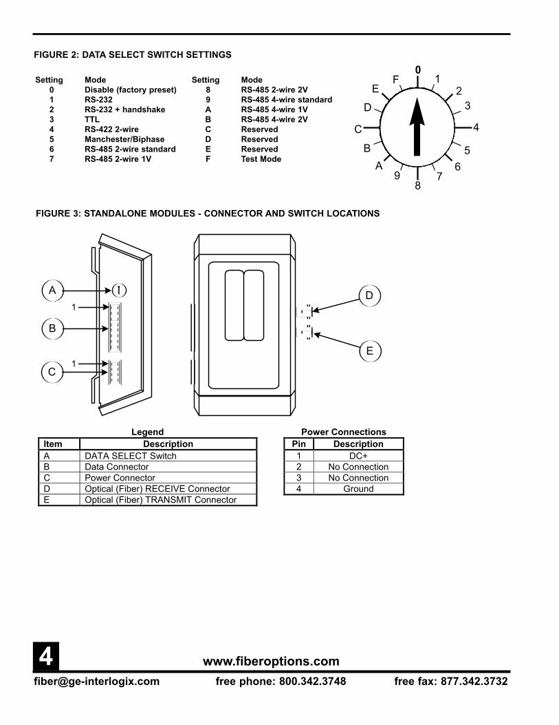
Using the rotary DATA SELECT switch, select a valid dataformat according to the DATA SELECT settings shown inFigure 2. See Figures 3 and 4 for the location of the DATASELECT switch.
NOTE: If the link is going to support RS-485, refer to RS-485APPLICATION NOTES on page 7.
Alarm Jumper
Rack cards are supplied with an alarm function that activatesif the optical signal input to the receiver fails. The alarm isalways indicated on the front panel of the card by a redLEVEL/LOSSTM LED. The alarm may also be output to therack power supply, where a sonalert (audible alarm) and alarmoutput contact closure may be activated.
The alarm is set to ON (ACTIVE) at the factory with jumperJP4 set to position 1-2. If the alarm output is not desired,remove jumper JP4 or move it to position 2 (OFF) only. Referto Figure 4.
NOTE: Setting alarm inactive does not affect the operation ofthe LEVEL/LOSSTM LED. Loss of optical signal will alwaysbe indicated by a red LEVEL/LOSSTM LED.
Data Translation
The data translation capability of the S710DV series is uniquein the industry. It allows translation from one format to anoth-er, thus eliminating the need for external translation devices.Data translation examples are shown in Table 1.
The translation is in the physical layer only; it cannot interpretspecific protocols, nor translate commands. Due to the encod-ing schemes utilized in Manchester and Biphase, these formatsare exempt from translation.
CONNECTIONS
Data Connections
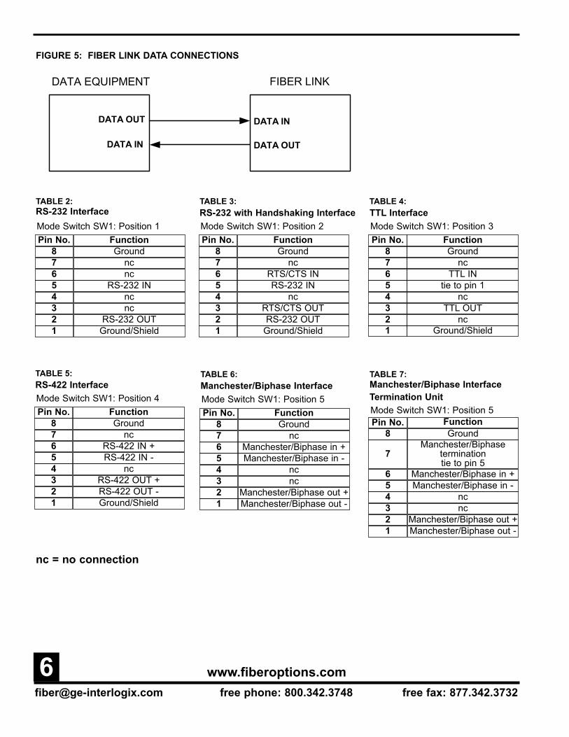
Data connections are made to the 8-pin removable screw ter-minal on the S710D according to the selected format. Refer toTables 2 through 10. When connecting data cables, alwayswire the DATA OUT pins on the data equipment to the DATAIN pins on the fiber links, and the DATA IN pins on the dataequipment to the DATA OUT pins on the fiber links. SeeFigure 5.
See Figures 3 and 4 for the location and orientation of the dataconnector.
Fiber Optic Cable Connection
Most cable manufacturers identify the individual fibers in thecable. Select appropriately terminated fiber and mark bothends with unique identification label (e.g. for cable no. 03,fiber no. 08) to ensure that the fiber connected to the near endis the same one that is connected to the far end.
The proper optical connection will link the transmitter'sTRANSMIT (OUT) port to the receiver's RECEIVE (IN) port.See Figures 3 and 4.
1. Wipe the inside of the port’s sleeve with a lint-free pipecleaner moistened with reagent-grade isopropyl alcohol. Blowdry with dry air.
2. Clean the connector using a lint-free cloth dampened withalcohol to thoroughly wipe the side and end of the ferrule.Blow the ferrule dry with dry air. Visually inspect the ferrulefor lint.
3. Fasten the fiber optic cable to the port. As a convenience tothe installer, one-fiber units have been fitted with an angledoptical connector to permit easy access.
Power Connections
Standalone ModulesAll S710D standalone modules are powered by 12 - 16 VDC.Connect input power according to the label on the module. SeeFigure 3.
[email protected] free phone: 800.342.3748 free fax: 877.342.3732
4
FIGURE 2: DATA SELECT SWITCH SETTINGS
Setting Mode0 Disable (factory preset)1 RS-2322 RS-232 + handshake3 TTL4 RS-422 2-wire5 Manchester/Biphase6 RS-485 2-wire standard7 RS-485 2-wire 1V
Setting Mode8 RS-485 2-wire 2V9 RS-485 4-wire standardA RS-485 4-wire 1VB RS-485 4-wire 2VC ReservedD ReservedE ReservedF Test Mode
F 10
ED
23
56
78
C
BA
9
4
B
A
C
1D
E1
FIGURE 3: STANDALONE MODULES - CONNECTOR AND SWITCH LOCATIONS
Legend Item Description A DATA SELECT Switch B Data Connector C Power Connector D Optical (Fiber) RECEIVE Connector E Optical (Fiber) TRANSMIT Connector
Power Connections Pin Description 1 DC+ 2 No Connection 3 No Connection 4 Ground

[email protected] free phone: 800.342.3748 free fax: 877.342.3732
5
FIGURE 4: RACK-MOUNT MODULE
B
SW1
8
1JP4
ALARM
1 2
A
C
D
E
Legend Item Description
A DATA SELECT Switch B ALARM Jumper C Optical (Fiber) TRANSMIT Connector D Data Connector E Optical (Fiber) RECEIVE Connector
TABLE 1: DATA TRANSLATIONS
NOTE: When configuring a pair of transceivers to translate data, the unit originating a signal is considered thetransmitter and the unit receiving and translating the signal is considered the receiver.
Translation TX
Switch Setting
RX Switch Setting
Comment
TTL RS-232, 3 wire 3 1 Signal level conversion. RS-232, 3 wire TTL 1 3 Signal level conversion. TTL RS-422 3 4 Single Ended to Differential Conversion. RS-422 TTL 4 3 Differential to Single Ended Conversion. RS-232, 3 wire RS-422 1 4 Single Ended to Differential Conversion. RS-422 RS-232, 3 wire 4 1 Differential to Single Ended Conversion. RS-232, 5 wire RS-485 2 7 - A RS232 Handshaking bit is used to indicate tri-state. RS-485 RS-232, 5 wire 7 – A 2 Tri-State detection circuitry activates handshaking bit.
[email protected] free phone: 800.342.3748 free fax: 877.342.3732
6
DATA EQUIPMENT
DATA OUT
DATA IN
FIBER LINK
DATA OUT
DATA IN
FIGURE 5: FIBER LINK DATA CONNECTIONS
Pin No. Function8 Ground7 nc6 nc5 RS-232 IN4 nc3 nc2 RS-232 OUT1 Ground/Shield
Mode Switch SW1: Position 1RS-232 Interface
Pin No. Function8 Ground7 nc6 RTS/CTS IN5 RS-232 IN4 nc3 RTS/CTS OUT2 RS-232 OUT1 Ground/Shield
Mode Switch SW1: Position 2RS-232 with Handshaking Interface
Pin No. Function8 Ground7 nc6 TTL IN5 tie to pin 14 nc3 TTL OUT2 nc1 Ground/Shield
Mode Switch SW1: Position 3TTL Interface
Pin No. Function8 Ground7 nc6 RS-422 IN +5 RS-422 IN -4 nc3 RS-422 OUT +2 RS-422 OUT -1 Ground/Shield
Mode Switch SW1: Position 4RS-422 Interface
Pin No. Function8 Ground7 nc6 Manchester/Biphase in +
3 nc
5 Manchester/Biphase in -4 nc
2 Manchester/Biphase out +1 Manchester/Biphase out -
Mode Switch SW1: Position 5Manchester/Biphase Interface
Pin No. Function8 Ground
6 Manchester/Biphase in +
3 nc
5 Manchester/Biphase in -4 nc
2 Manchester/Biphase out +1 Manchester/Biphase out -
7Manchester/Biphase
termination tie to pin 5
Mode Switch SW1: Position 5
Manchester/Biphase InterfaceTermination Unit
TABLE 2: TABLE 3: TABLE 4:
TABLE 5: TABLE 6: TABLE 7:
nc = no connection

[email protected] free phone: 800.342.3748 free fax: 877.342.3732
7
Rack ModulesPower connections are made automatically when the card isinstalled. To supply power to the rack, connect the rack powersupply to an AC outlet and set the power switch to ON.
SMARTSTM DIAGNOSTICS
The S710D has built in Status Monitoring And Reliability TestSystem (SMARTSTM) diagnostic capabilities. This includesLED indicators for monitoring data and optical status.
LED Operation
Refer to the Table 11 for an explanation of how to diagnosesystem faults using the LEDs built into the Fiber Options units.
The S710D has 4 LED indicators that are very useful indescribing the current state of operation, as well as the currentstatus of data flow and fiber optic signal strength. These indi-cators are LEVEL/LOSSM, DATA IN, DATA OUT, andENABLED. See Figure 6. The LEDs function as follows:
LEVEL/LOSSTM IndicatorThis LED is useful for indicating the relative optical signalstrength at the fiber optic receiver. When sufficient opticalpower is being received, the LED is green. If no or insufficientoptical power is received, the LED will be red. All data willdefault to it's failure state level to eliminate bus contention.
DATA IN IndicatorThe Data In LED indicates the state of the data being input tothe S710D over copper. A green DATA IN LED indicates a
logic HIGH is present on the copper inputs. A yellow DATAIN LED indicates a logic LOW is present on the copper. Nocolor (OFF) indicates a tri-state or high impedance input.
Therefore, this can be used to determine the resting state ofyour equipment. Unique to the industry, the S710D has specialcircuitry to capture data transitions and make them visible onthe LEDs. High-speed bursts of activity, previously unde-tectable by standard LED circuits, can easily be seen by thisspecial circuitry.
DATA OUT IndicatorThe DATA OUT LED functions identically to the DATA INLED except that the LED represents data that is being outputfrom the unit. This LED has the same high-speed capture cir-cuitry described in the DATA IN section.
ENABLED IndicatorThis LED has three states;. green indicates a valid mode hasbeen selected, red indicates an invalid mode (spare or test-mode) has been selected, or flashing red/green indicates that NO mode has been selected.
TEST MODE
Test mode allows the user to verify the operation of the copperreceiver/driver circuit in an S710D, as well as the fiber con-nection from one S710D to another. Using the test mode issimple:
1. Switch the S710D to be tested into position F (TEST-MODE) on the DATA SELECT rotary switch. At this endonly, wire the connector as shown in Table 10.
nc = no connection
Pin No. Function8 Ground7 RS-485 termination - tie to pin 56 RS-485+5 RS-485 -4 +5 VDC BIAS OUT3 nc2 nc1 Ground/Shield
Position 8 = 2V offset
Mode Switch SW1: RS-485 2-Wire Interface
Position 7 = 1V offsetPosition 6 = standard offset
Pin No. Function8 Ground7 RS-485 termination - tie to pin 56 RS-485 in +5 RS-485 in -4 +5 VDC BIAS OUT3 RS-485 out +2 RS-485 out -1 Ground/Shield
Position B = 2V offset
Mode Switch SW1: RS-485 4-Wire Interface
Position A = 1V offsetPosition 9 = standard offset
Pin No. Function8 Ground7 nc6 tie to pin 35 tie to pin 24 nc3 tie to pin 62 tie to pin 51 nc
Mode Switch SW1: Position FTest Mode Loopback InterfaceTABLE 10:
TABLE 9:TABLE 8:
2. At the receiving (or opposite) end, switch the S710D toposition 9 on the rotary switch.
In test mode, the transmitter should behave as follows:a. ENABLED LED is red, indicating that a valid data formathas not been selected.
b. DATA OUT LED is slowly flashing between amber, green,and off. This indicates that the test mode is generating an out-put pattern and sending it out on copper.
c. DATA IN LED should mimic the DATA OUT LED. Thisindicates a good, proper loopback connection, and proves thatthe data transmit/receive circuitry is working properly.
d. LEVEL/LOSSTM LED may be red or green - indicatesreceived fiber signal strength but does not affect this part of thetest.
The receiver (position 9) should behave as follows:
a. ENABLED LED is green indicating a valid data format isselected.
b. DATA OUT LED should slowly flash amber, green, off.This indicates that the fiber path from the unit set forTESTMODE is reliable.
c. DATA IN LED should be OFF since there is no input cop-per connection made.
d. LEVEL/LOSSTM LED should be steady green, indicatingthat sufficient optical power is being received.
After the test has been performed at one end, swap switch posi-tions and connectors to perform the test on the other end.Having done this, you have proven that the copper-in-to-fiber-to-copper-out conversion is working in both directions.
RS-485 APPLICATION NOTES
The S710D is configurable for both full-duplex (4-wire) andhalf-duplex (2-wire) operation. It can be used for interfacingto systems adhering strictly to the RS-485 specification and foruse with systems that use a modified, "fail-safe biased" RS-485bus.
Connection
Use high quality twisted-pair wiring, and make sure all con-nection points are clean and tight. A loose connection on oneof the wires can appear to function, yet cause intermittenterrors: DATA LEDs may be flashing as signals pass through
the system, but those signals will be corrupt.
Configuration
Fiber Options Universal Data units are designed to work withvirtually any RS-485 system. Unfortunately, some systemsoperate on a "modified" version of RS-485; they use failsafebiasing to pull up/down their bus during a tri-state condition.In a standard RS-485 system, when a driver on a properly ter-minated bus goes into tri-state (inactive), the voltage betweenthe differential outputs should be less than 200 millivolts.(This is what is considered "standard offset" in the productinstruction manuals). A differential output tri-state voltage thissmall can cause some nonstandard systems to latch up, sincethey are designed for much larger, "fail-safe," offsets.
To be able to interface to such equipment, Fiber OptionsUniversal Data products offer two more "offset" level modes.That is, the maximum differential input voltage that can beapplied where it will be perceived to be in tri-state. Of course,the equipment manufacturer does not disclose this information.In most cases, the Fiber Options unit should be configured for"standard offset" operation. When the system is operatingproperly, the DATA IN and DATA OUT LEDs will be off whenthere is no communication (tri-state) and they will flash whendata is being sent or received. In the case where the link is notfunctioning properly, (LEDs will most likely not turn off),change the DATA SELECT switch on the unit to a higher off-set mode. First try 1 V, then 2 V. If simply switching the modeswitch does not prove effective, the offset level may have to beemulated at one end of the system by using pull-up/down resis-tors on the data connector. The S710D has a +5 V bias pin andground pins on the connector for this purpose. Contact equip-ment manufacturer's technical support for recommended resis-tor values and configuration.
Termination
RS-485 systems need to be properly terminated in order towork reliably. Exactly two terminating resistors are used oneach RS485 bus, at the furthest ends of the link.
[email protected] free phone: 800.342.3748 free fax: 877.342.3732
8

[email protected] free phone: 800.342.3748 free fax: 877.342.3732
9
TABLE 11: LED DIAGNOSTIC INDICATORS
FIGURE 6: 710D RACK-MOUNT FRONT PANEL
LED Name Color Indicates/Corrective Action Green Sufficient optical power received. No action required. LEVEL/
LOSS Red Insufficient optical power received. Verify fiber connected & within optical budget, receiver power on.
Green Logic high into unit. No action required. Yellow Logic low into unit. No action required. DATA IN
off Tri-state or disabled condition. Verify data connected, data source has power. Green Logic high received over fiber. No action required. Yellow Logic low received over the fiber. No action required. DATA OUT
Off Tri-state received over fiber or disabled condition. No action required. Green DATA SELECT switch set to valid mode. No action required
Flashing Red/Green DATA SELECT switch in Disabled position (position 0). Select a valid data format. ENABLED
Red DATA SELECT switch set to Test Mode or invalid data format. Check DATA SELECT switch conforms to desired configuration – may be valid.
710
LVL/LOSS
ENABLED
DATA IN
DATA OUT
All specifications are subject to change without notice. Information furnished by FIBER OPTIONS isbelieved to be accurate and reliable. However, no responsibility or liability is assumed by FIBEROPTIONS for its use, nor for any infringement of patents or other rights of third parties which mayresult from its use. No license is granted by implication or otherwise under any patent or other rightsof FIBER OPTIONS.
11-0710D-ECopyright 2001 by FIBER OPTIONS.All rights reserved. 021115
www.fiberoptions.com80 Orville Drive, Bohemia NY 11716-2533
US Tel: 631-567-8320 Fax: 631-567-8322800-342-3748 877-FiberFax (877-342-3732)
UK Tel: +44 113 238 1668 Fax: +44 113 253 8121 Australia Tel: +61 3 9370 9192 Fax: +61 3 9370 9936
France Tel: +33 01 60 86 54 53 Fax: +33 01 60 86 86 04Germany Tel: +49 700 34237678 Fax: +49 36256 21991
Hong Kong Tel: +852 2907 8108 Fax: +852 2142 5063Latin America Tel: 800-342-3748 Fax: 877-342-3732
. . . light years ahead™
INSTRUCTIONMANUAL
NOTE: The resistors for terminating RS-485 data are built intothe S710D.
If the S710D is positioned at either end of the data bus, termi-nate the unit by connecting a jumper between the pins indicat-ed in Tables 8 and 9.
If the terminating resistors are left out, the tri-state conditionwill not be detected, and the bus may lock up. If there are toomany terminations on the bus, signal levels may drop too low, or driver circuitry may fail.
OPERATION
S710D links operate automatically once installed. To executethe test mode, see page 7. For an explanation of LED colorcodes, see LED OPERATION on page 7and Table 11.
MAINTENANCE
There is no operator maintenance other than keeping the unitsclean.
CONTACTING FIBER OPTIONS
If you cannot determine the cause of your problem and are inthe U.S. or Canada, call the Fiber Options Headquarters inBohemia, NY. If you are outside the U.S. or Canada, call theclosest international office listed on the back page of this man-ual.
Have the following information available: exact model numberand product code of your fiber-optic links, and a listing of thediagnostic indicators and their respective color/condition.
SHIPPING AND PACKAGING
Before shipping or transporting your Fiber Options unit, packit securely to prevent damage that could occur in transit. Usecare to protect all connectors, LEDs, and corners from possibledamage.
RETURNS TO FIBER OPTIONS
If any equipment must be returned to Fiber Options for repairor replacement, you must obtain authorization from our ReturnAuthorization department before shipping.
If you are in the U.S. or Canada, call our NY headquarters at631-567-8320 or 800-342-3748.
Customers in other countries should contact their regional rep-resentative listed on the back cover of this manual. A ReturnAuthorizations representative will provide full instructions forreturning your product at that time.
NOTE: All authorized returns must be clearly marked with theReturn Authorization information. Please follow the instruc-tions completely.
NOTE: Fiber Options will not accept return delivery of anyproduct without prior authorization.