s81-hs panel presentation
TRANSCRIPT

Fire and Gas - Oil & Gas - Industrial
- Power
Marco Santucci Scame Sistemi

15
Conventional F&G Philosophy
Point type Smoke/heat detector Manual call point Addressable beacon and sounder
Actuation of discharge Control of delays Dedicated fire detection
Gas detectors Flame detectors HSSD High power beacons Remote singalling interface with other systems Main HMI IEC61508 for safety PLCs continous mode

16
Problems?
Designed for building
Actuation only Designed for continous operation
Main interface shall be EN54
INTERFACING COMMUNICATION
ISSUES
1 The full function relies on all the three systems 2 Maintenance (3/4 power supplies and batteries)
3 TCO (NR Costs and Running Costs)

19
All in one
Addressable and conventional fire detection
Automatic fire extinguishing
Gas detection
Security, access control, CCTV, BMS, Environmental.

SIL2 & SIL3
Programmable Electronic System
for Safety-Related Applications
Follow Video demonstration on YouTube http://www.youtube.com/user/Scamesistemi

21
Panel Composition

22
HW & SW Features
Distributed intelligence
High availability
High fault tolerance
HOT SWAP of
CPUs, I/O cards, power
supply units, display
Easy maintenance
SIL2 and SIL3 rated
for safety functions

23
Enclosures
Wall Mount 400x600x700h mm
1 Expansion rack, max 13 cards
1 or 2 CPUs
SIL2 Max
EN54
EN12094
Fire and Gas

24
Enclosures
Wall Mount 400x600x1100h mm
2 Expansion racks, max 26 cards
1 or 2 CPUs
SIL2 & SIL3
EN54
EN12094
Fire and Gas

25
Enclosures
Floor standing single door
800x800x2100h mm
Max 6 Expansion racks
1 or 2 CPUs
SIL2 & SIL3
EN54
EN12094
UL
Fire and Gas
Hot swap Power supply

26
Enclosures
Floor standing double door
1600x800x2100h mm
Max 10 Expansion racks
1 or 2 CPUs
SIL2 & SIL3
EN54
EN12094
Fire and Gas
Hot swap Power supply (2x)

27
Enclosures
Compact Wall Mount 500x250x700h mm
1 non-expandable rack, max 8 cards
1 or 2 CPUs
SIL2
EN54
EN12094
Fire and Gas

28
Enclosures
Ex-nR for Zone 2 800x800x2100h mm
All Stainless Steel
Max 6 Expansion racks
1 or 2 CPUs
SIL2 & SIL3
EN54
EN12094
Fire and Gas

29
Enclosures
Ex-d for Zone 1 (EJB5)
1 non-expandable rack, max 8 cards
1 or 2 CPUs
SIL2
EN54
EN12094
Fire and Gas

30
Enclosures
Demo unit in flight case
Equipped with 1 rack and Sample cards
2 CPUs
SIL2
2 Simulation push-buttons
2 Simulation LEDs
1 Smoke detector
1 manual call point
For demo and training
31
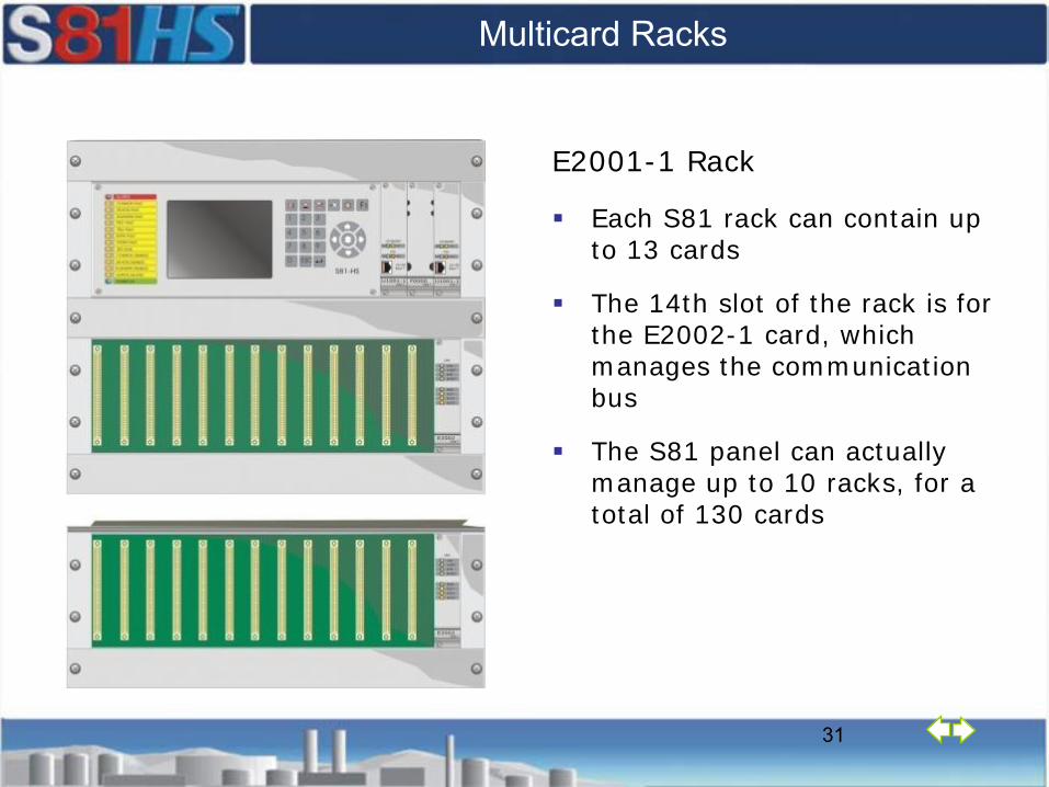
Multicard Racks
E2001-1 Rack
Each S81 rack can contain up to 13 cards
The 14th slot of the rack is for the E2002-1 card, which manages the communication bus
The S81 panel can actually manage up to 10 racks, for a total of 130 cards

32
Card name F3002 F4001 F4002 F4003
Input lines 8 1 2 8
Kind of input Digital Analog 4-20 mA Analog 4-20 mA Analog 4-20 mA
Line monitoring S.C., O.C. 0-24 mA 0-24 mA 0-24 mA
Threshold levels 2 each line 2 2 each line 2 each line
Visual indication Led Led, Bar Graph ,
display Led , display Led
Card monitoring Self test Self test Self test Self test
SIL 2 rated Single Single Single Single
SIL 3 rated Redundant Redundant Redundant Redundant
Analog and digital input cards

33
Collective type connections
Different brand/type detectors (upgrading existing systems)
32 detectors per line (as per UNI 9795 standard)
Short and open circuit monitoring
Pre-alarm, alarm, alarm verification on each line

34
Connection of analogue sensors
4-20 mA inputs
Direct reading on display
Connection of gas, oxygen, vapour, heat, level sensors
Return of input signal towards external systems
SIL 2 certified sensors

35
Card name F7002 F7009 F7007 F7010
Devices manufacturer HOCHIKI APOLLO SCAME Notifier by
Honeywell
Loop protocol ESP XP95 / Discovery SSP System Sensor
Applications Fire detection Fire detection Security, Env.,
BMS, Gas Fire detection
Addressable each 127 126 127 99 in, 99 out.
I/O digital modules I/O multichannel I/O multichannel I/O multichannel I/O multichannel
Analogue inputs None None 4-20 mA 4-20 mA
Field wiring Loop (ring 3km) Loop (ring 3km) Loop (ring 3km) Loop
SIL rated None SIL 2 None None
Addressable cards
Can be used
together

36
Card name F7009 F7007
Devices manufacturer APOLLO SCAME
Loop protocol XP95 / Discovery SSP
Applications Fire detection Security, Env., BMS, Gas
Number of devices per loop 126 127
I/O digital modules I/O multichannel I/O multichannel
Analogue inputs None 4-20 mA
Field wiring Loop (ring 3km) Loop (ring 3km)
SIL rated SIL 2 with Discovery SIL2 devices None
Addressable cards
How many loops?

37
Connection of analogue addressable devices
Fire detection
Detection (input) and control (output) on the same loop
SIL 2 certified addressable detectors

38
Industrial anti-intrusion alarm
4-20mA 8 x Digital IN 4 x Supervised Digital IN 8 x Digital OUT. Mixed I/Os Access control, BMS, integration with CCTV … in the same loop. Gathering of statuses for safety functons
The security system is certified to level II

39
Card name F5001 F5004 F5003 F5002
Ouput lines 8 4 8 16
Channel output current 500 mA 2 A 250 mA 500 mA (Total)
Line monitoring S.C., O.C. S.C., O.C. Reversal polarity None
Direct pulse line monit. Yes Yes None None
Relay card None None T8008 - 4 ch. Yes
Outputs can be paralleled Yes Yes None None
SIL 2 rated Single Single None None
SIL 3 rated Redundant Redundant None None
Output cards

40
Monitored actuators
Dedicated command for each actuator
Line monitoring for short circuit and open circuit
Card-line diagnostics
Direct or reverse polarity monitoring
SIL 2 certified actuators

41
Cards name F7006 F7008 F6002
Field protocol Modbus RTU Modbus RS485 S81
Applications Data link Weighing bottles Special logics
Capacity 512 in, 512 out. 32 bottles 100 logic devices
Mode Master or Slave 2 alarm thresholds Flip-flop, toggle, timer.
Field wiring Rs232-Rs485 Rs 485 Internal bus
SIL rated None (redundant) None None
Special cards
42
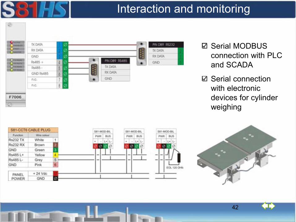
Interaction and monitoring
Serial MODBUS connection with PLC and SCADA
Serial connection with electronic devices for cylinder weighing

43
Extinguishing control card F6001
Electrical automatic control and delay device (e.c.d.) certified to EN 12094-1 standard
Mandatory, in Europe for gas-based extinguishing systems
Able to manage all the virtual devices necessary for an extinguishing application in a zone
Physical I/O’s are controlled by other S81 input and output cards
S81 control panel can manage up to 64 F6001 cards
44
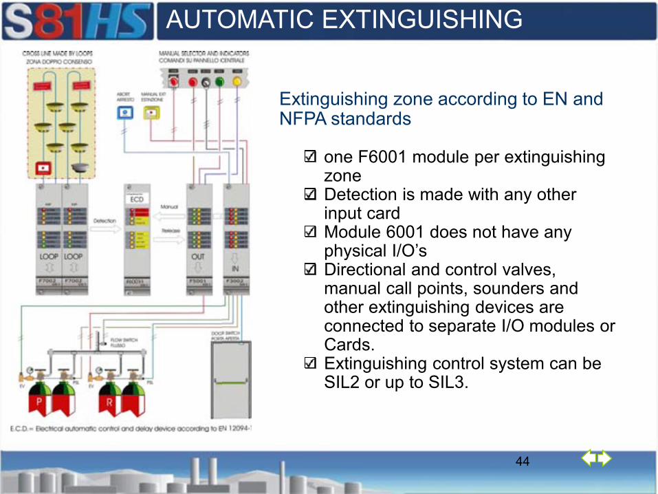
Extinguishing zone according to EN and NFPA standards
one F6001 module per extinguishing zone Detection is made with any other input cardModule 6001 does not have any physical I/O’s Directional and control valves, manual call points, sounders and other extinguishing devices are connected to separate I/O modules or Cards. Extinguishing control system can be SIL2 or up to SIL3.
AUTOMATIC EXTINGUISHING

45
Example of a SIL function
SIL certified detectors on addressable loop
SIL certified actuators (solenoids, deluge valves, monitors)
S81-HS panel with logic solver functions

46
EN54-4 / UL Power Supply Units
PU-A003-1 Power Unit
2.5 A
PU-A008-1 Power Unit – HOT SWAP
AC/DC Converter
2 or 4 x 20A Battery Charger
120 Ah
PU-A005-1 AC/DC
Converter 4 A
PU-A004-1 Battery Charger 65 Ah

ProS81 Configuration Program
47
1) Definition of inputs
2) Definition of outputs
3) Definition of rules
4) Check of data validity
Runs on any Windows operating system
Communication with panel via RS232 or TCP/IP
Configuration is protected through password and USB dongle key
ProS81

Check of Data Validity
48

49
Very short repair time
Front plug-in/out cards Automatic monitoring of cards
and CPU fault Automatic and safe disabling
of malfunctioning cards Cards can be hot swapped
with compatible cards CPU self configuring and
cheking the new card CPU can be duplicated for
redundant solution
Follow Hot Swap demonstration on YouTube http://www.youtube.com/user/Scamesistemi

50
Hot swap in three key points
1 - No switching off Switchin off an F&G system means actuate the whole process shut down procedure with consequent down time and loss of production
2 - All the rest keeps on working When replacing a module all other safety functions are fully guaranteed. If the module is installed with redundancy its safety function is guaranteed too.
3 - No need for re-programming The new module configuration is automatically updated by the main CPUs. Anyone can execute the repair.

51
Hot swap in three steps
1 – Take the module out Undo the screws and remove the module. (Silence the buzzer if annoying)
2 – Put the new module in Slide the module and screw.
3 – Wait for the update Automatic update is a matter of a few seconds depending on the module type and complexity of its configuration. When update is finished the fault(s) indication goes away.

52
Cards can be redundant On the same control panel can coexist: Redundant links (SIL3)
• Detectors for high risks • Alarm buttons in hazard area • Evacuation area horns
Non redundant links (SIL2 or non SIL)
• Smoke and fire detectors (safety) for building
• Addressable I/O modules for building

53
Programming & Networking IRIDE management and supervision program
ProS81 for local or remote programming
OPC server for integration with third parties systems (SCADA’s PLC’s etc.)
TCP/IP protocol LAN and WAN connection via
Ethernet, for interconnection of up to 99 panels
Modbus RTU protocol, no limits in number of panels
Other protocols upon request
Integration with other systems achieved via
Hardwired signals (SIL2, SIL3) - safety related Modbus signals – important TCP/IP – useful Addressable modules - useful

54
OPC Server, Iride and FO ring

56
SIL2 Safety Functions
1. Analogue detection and actuation
PFDavg = 1,4 10-4
SFF = > 90%
HFT = 0
2. Conventional detection and actuation
PFDavg = 9,4 10-5
SFF = > 90%
HFT = 0
3. Automatic Fire Extinguishing
PFDavg = 7,8 10-6
SFF = > 90%
HFT = 0
SIL2 Certified
PFDavg = Average Probability of Failure on Demand
SFF = Safe Failure Fraction; HFT= Hardware Fault Tolerance

57
SIL3 Safety Functions
1. Analogue detection and actuation
PFDavg = 5,0 10-6
SFF = > 90%
HFT = 1
2. Conventional detection and actuation
PFDavg = 4,0 10-6
SFF = > 90%
HFT=1
3. Automatic Fire Extinguishing
PFDavg = 3,6 10-6
SFF = > 90%
HFT=1
PFDavg = Average Probability of Failure on Demand
SFF = Safe Failure Fraction; HFT= Hardware Fault Tolerance
SIL3 Certified
PFDavg

58
SIL Safety Functions
Addressable fire detection and actuation
Apollo Devices
Hot Swap Redundant Power Unit

61
Main Figures
S81HS control panel capacity UL EN
HW
Rack for each control panel 6 10
Cards for each rack 13
Maximum number of devices for each control panel
Single point 9,906 16,510
Addressable (subaddresses) 29,700+29,700
SW
Max number of zones (*1) 300+300
Max number of devices per zone (*2) 99+99+99
Max number of S81-HS on TCP/IP a network 99 (*1) = 300 safety zone and 300 security zone (*2) = 99 inputs, 99 outputs , 99 logic relationships/gates. Zone: ”portion of protected area”

62
Certifications Applicable standards Year Lab Report
EN 54-2 Fire detection and fire alarm systems - Control and indicating equipment
2008 IMQ 0051-CPD-0233
0051-CPD-0234
0051-CPD-0235
EN 54-4 Fire detection and fire alarm systems - Power supply equipment
2008 IMQ 44AH00060
EN 12094-1 Fixed fire fighting systems - Requirements for electrical automatic control and delay devices
2008 IMQ 0051-CPD-0137
0051-CPD-0138
0051-CPD-0139
IEC 61508 1-7: 2.0 Functional safety of programmable electronic safety-related Systems - Requirements for Safety Integrity Level (SIL2 & SIL3)
2013 TÜV TÜV968/EL 884,01/13
EN 50402: 2005 Electrical apparatus for the detection and measurements of combustible or toxic gases or vapours or of oxygen
2009 TÜV FS 28709180
CEI 79-2:1998
CEI 79:2 ab2000
Control and indicating equipment for alarm systems (Italian standard for anti-intrusion systems)
2008 IMQ CA12.00953
GOST-K, GOST-R Fire detection and fire alarm control panel 2009 GH POCC IT.AB24.B01128
NFPA 72
UL864, Control Units and Accessories for Fire Alarm Systems UL2017, General-Purpose Signaling Devices and Systems
2012 UL 20121002-S24857

63
SUMMARY
Addressable and Conventional Fire Detection
Automatic Fire Extinguishing
Gas Detection
Security, Access control, CCTV, etc.
ALL IN ONE
Modular, sizeable to need
Distributed intelligence
High availability, fault tolerance
HOT SWAP
SIL2 and SIL3
Follow Video demonstration on YouTube http://www.youtube.com/user/Scamesistemi