saara israa frej a-interface over internet …
TRANSCRIPT

SAARA ISRAA FREJ
A-INTERFACE OVER INTERNET PROTOCOL FOR USER-PLANE
CONNECTION OPTIMIZATION IN GSM/EDGE RADIO ACCESS
NETWORK
Master of Science Thesis
Examiner: Professor Jarmo Harju Examiner and topic approved on 09.12.2009

I
ABSTRACT TAMPERE UNIVERSITY OF TECHNOLOGY Master’s Degree Programme in Information Technology FREJ, SAARA ISRAA: A-Interface Over Internet Protocol For User-Plane Connection Optimization In GSM/EDGE Radio Access Network Master of Science Thesis, 54 pages, 4 Appendix page(s) January 2018 Major: Communications Engineering Examiner: Professor Jarmo Harju Keywords: GERAN, Media Gateway, Base Site Controller, A-interface over IP, bandwidth optimization, gain, header compression, multiplexing, RTP and RTCP negotiation.
Clearly, future mobile network traffic will be strongly dominated by Internet Protocol
centric (IP-centric) packet traffic. Indeed, the basic connectivity technology is changing
from Time Division Multiplexing (TDM) and Asynchronous Transfer Mode (ATM) to
packet technologies.
For this reason alone, it makes good sense for service providers, including Nokia
Siemens Networks Oy (NSN), to migrate GSM/EDGE (GERAN) backhaul from T1/E1
TDM and ATM to Ethernet transport.
Certainly, the cost of transport is also the biggest driver for the evolution from TDM to
packet-based transport. That is why wide transport technology portfolio and system
competence on packet networks and technologies are needed to create an optimum solution
for future mobile and converged transport networks.
In fact, on one hand, end-users are less concerned about technical novelties and they
desire to benefit from more and more new services at lower costs. Basically, they are only
concerned of newer cheaper services and offers.
On the other hand, operators’ main concern is to achieve low-priced basic voice
services that are always essential for carriers to survive in future. Besides this, original and
new value-added services are the keystone for carriers to flourish.
This thesis will cover a detailed study about the main motivations and benefits from
using IP as a transport protocol for specifically A-interface in GERAN for Circuit Switched
User-Plane (CS-UP) connection, in addition to the required protocols.
The main study in this document will be around Real Time Protocol (RTP), Real Time
Control Protocol (RTCP) negotiation for RTP packets multiplexing, for both cases, with
and without RTP header compression. The focus will be about the communication between
the Base Station Controller (BSC) and the Media GateWay (MGW), the bandwidth gain in
accordance to the multiplexing delay for processing and buffering, the voice Quality of
Service (QoS) and some other parameters.

II
CONTENTS
ABSTRACT.........................................................................................................................................I
PREFACE ........................................................................................................................................ IV
LIST OF FIGURES ......................................................................................................................... VI
LIST OF TABLES ......................................................................................................................... VIII
ABBREVIATIONS AND NOTATIONS ........................................................................................ IX
1. INTRODUCTION .......................................................................................................................1
1.1. Motivations .......................................................................................................................1
1.2. Goals and scope ..............................................................................................................4
1.3. Thesis structure ..............................................................................................................5
2. BACKGROUND ........................................................................................................................7
2.1. GSM /EDGE (GERAN) overview ...................................................................................7
2.1.1. Current system’s architecture .............................................................................8
2.1.2. Current system’s interfaces .............................................................................. 10
2.2. Voice Encoding ............................................................................................................. 13
2.2.1. Voice transcoder .................................................................................................. 14
2.2.2. Voice CODECs ...................................................................................................... 15
2.2.3. Effects of coding algorithms ............................................................................. 17
3. INTERWORKING AND TRANSPORT OVER IP .............................................................. 19
3.1. Internet Protocol (IP) ................................................................................................... 20
3.2. User Datagram Protocol (UDP) ................................................................................. 21
3.3. Session Initiation Protocol (SIP) .............................................................................. 22
3.4. Real Time Protocol (RTP) ........................................................................................... 22
3.5. Real Time Control Protocol (RTCP) ........................................................................ 23
3.6. Voice Over IP (VoIP) and A-interface over IP ........................................................ 24
4. VOICE QUALITY ASPECTS ................................................................................................ 26
4.1. Voice Quality of Service (QoS) and Mean Opinion Score (MOS) .................... 26
4.2. Quality tolerances ........................................................................................................ 28
4.3. Quality and noise ......................................................................................................... 29
4.4. Service Level Agreement (SLA) ............................................................................... 30
4.5. Other parameters ......................................................................................................... 30
III
4.5.1. Packet delay .......................................................................................................... 30
4.5.2. Jitter and packet loss .......................................................................................... 31
4.5.3. Latency ................................................................................................................... 34
4.5.4. Redundancy schemes ........................................................................................ 34
4.5.5. Silence suppression, VAD and CNG ............................................................... 34
5. RTP MULTIPLEXING FOR A-INTERFACE OVER IP ..................................................... 35
5.1. Multiplexing features and different scenarios ...................................................... 35
5.1.1. Transport format for multiplexing ................................................................... 37
5.1.2. Transport without RTP header compression ............................................... 38
5.1.3. Transport with RTP header compression ...................................................... 39
5.1.4. Multiplexing negotiation via RTCP .................................................................. 41
5.2. Multiplexing effects on bandwidth gain ................................................................. 44
5.2.1. Buffering and Packet Delay Variation (PDV) ................................................. 46
5.2.2. Multiplexing wait time and effects on users’ satisfaction ......................... 47
6. CONCLUSION ........................................................................................................................ 49
REFERENCES ............................................................................................................................... 52
Appendix ........................................................................................................................................ 55

IV
PREFACE
It is with happy heart that I sit down tonight to write this preface. Not just because of the
fast-approaching, long-awaited trip to Carthage, Tunisia -my home country-, but because of
the milestone crossed, and crossed soon at that. The completion of this thesis ends my
university studies as a master degree student, which is my second (my first one was
obtained in Tunisia back on February 2007). I take this opportunity to make
acknowledgements to everyone I know who has shaped my life, studies and work during
my stay in Finland.
At the very outset, I would like to wholeheartedly thank my supervisor Juha
Hartikainen, who has been my mentor throughout my work at Nokia Siemens Networks Oy
(NSN), Tampere, Finland. He has been my primer guide to achieve this work. His outright
friendliness and warm persona were immediately reassuring during my first apprehensive
days at NSN. As my boss during this master’s thesis work, his comments and
acknowledgeable insight have helped to shape this work.
Secondly, I would like to thank warmly my professor Jarmo Harju for being my
supervisor at Tampere University of Technology (TUT) for my thesis work. He has been
always there for me to help. He had supported and guided me and has been the source of
my inspiration at all the times, without which this thesis would not have been possible in its
present form. Even otherwise, I have learnt a lot from him, for which I am very grateful.
A few words about Finns, the country may be located in somewhat far-flung place, but
the attitudes of people are far from boorish. In my experience, as a student at least, the
Finns are sincere and warm people and friendly in their own discreet way. Because of their
generally simple upbringing and social rules, it is natural that they are not overtly
expressive or garrulous, and it is easy to mistake their unpretentiousness for rudeness.
Intelligent, aware, patriotic and yet modest, is how I would describe any “teekkari”.
One personal funny thing happened to me before coming to Finland to do my first
thesis work back on 2006 in Helsinki, was that I never checked where Finland is really
located geographically. In French, “Fin” means the end, and “land” in English of course it
means earth or so. I actually got scared as I had to travel to the “end of the earth”
Anyway, my first visit was the reason and main trigger that made me came back to the
country and study more, even after my graduation. Thanks to Finland, I got two lovely boys
Rami Armas and Sami Hédi Väätti respectively 5 and 2 years old. Both are the reason to
live my life happily no matter what happens. Even though I got delayed about the delivery
of my thesis report after the birth of my first child on 2011 and then the divorce, many
surgeries and moving from Tampere to Turku, etc. Life was not that easy I would say to a
Mediterranean single mother living abroad alone. They became my force and my source of

V
energy to finish what I first came to do in this country. My studies, my career and my
children are my life!
Finally but not last, I would like to say that good friends and companionship are very
important to keep homesickness at bay. This is especially true in a land where hours of
sunshine are precious. Big thanks to my neighbors and flat mates.
How can I end without mentioning my loving family? I would like to take this
opportunity to express my deepest gratitude to my father, my mother, and my sister for
everything they have done for me, starting from the moral support to the material one.
Thank you mother for brushing my hair and helping me putting my clothes and shoes on.
Thank you for taking care of me, etc, during the 2 months of the post-surgery period. I
would like to mention that the ulnar nerve transposition on my left elbow on 2009 was my
biggest obstacle at first during this thesis (the recovery took over a year), then the
emergency C-section on 2011, divorce on 2013 and another C-section on 2014, cervical
hernia on my neck starting from 2016… I would say that my path to achieve this work was
not easy at all. Luckily, thanks to my strong will, perseverance and support from everyone
including my supervisor mainly, I could get my strengths back and get hopefully back to
track in this society and be able to support my kids. At each step of my life, I am
increasingly aware that I am fortunate indeed to have a wonderful family and friends like
mine. I can only say thank you everyone!
Saara Israa FREJ
Turku, May 2016

VI
LIST OF FIGURES
Figure 1. Mobile Operator's cost of data transport .............................................................................1
Figure 2. The growth of the networking market ..................................................................................2
Figure 3. Mobile data traffic 2011–2012 and CAGR 2012–2018 (growth by region) ..........................3
Figure 4. Mobile data traffic (GB/month per smartphone) .................................................................3
Figure 5. Global mobile data traffic (ExaBytes/month) .......................................................................4
Figure 6. GERAN’s main overview ........................................................................................................8
Figure 7. System's architecture ............................................................................................................9
Figure 8. Supported Abis and AoIP configurations, when transcoding is in BSS ............................. 10
Figure 9. Supported Abis and AoIP configurations, when transcoding is in CN ............................... 11
Figure 10. CODECs in different interfaces, when TC is in MGW (CODECs are examples only) ........ 15
Figure 11. VoIP Protocols within the OSI Model stack...................................................................... 20
Figure 12. IPv4 header ...................................................................................................................... 21
Figure 13. UDP header ...................................................................................................................... 21
Figure 14. RTP header ....................................................................................................................... 22
Figure 15. Generation of RTP packets ............................................................................................... 23
Figure 16. Jitter-free stream of RTP packets ..................................................................................... 23
Figure 17. Legacy architecture of VoIP and AoIP .............................................................................. 24
Figure 18. Architecture for Compressed speech over IP, with transcoders in BSS ........................... 25
Figure 19. Architecture for Compressed speech over IP, with transcoder-less BSS ......................... 25
Figure 20. QoS parameters ............................................................................................................... 26
Figure 21. Jitter formation ................................................................................................................ 32
Figure 22. A jittered RTP packet........................................................................................................ 32
Figure 23. RTP packet loss ................................................................................................................. 33
Figure 24. IP Protocol stack for the transport network User-Plane .................................................. 35
Figure 25. Multiplexing technique (T = Time) ................................................................................... 35
Figure 26. Proposed Solution: AoIP TransCoder (TC) in Base Station Subsystem (BSS) .................. 36
Figure 27. Proposed Solution: AoIP TC in Media GateWay (MGW) ................................................. 36
Figure 28. Transport format .............................................................................................................. 37
Figure 29. Muxing/demuxing process ............................................................................................... 37
Figure 30. Reducing header overhead by packet multiplexing ........................................................ 38
Figure 31. UDP/IP Packet with multiplexed RTP/NbFP payload PDUs without CRTP header .......... 39
Figure 32. UDP/IP Packet with multiplexed RTP/NbFP payload PDUs with CRTP header ................ 40
Figure 33. Transport with RTP header compression ......................................................................... 41
Figure 34. Comparison of IP/RTP packets’ size before and after header compression .................... 41
Figure 35. Packet size reduction after header compression............................................................. 41
Figure 36. RTCP Multiplexing packet ................................................................................................ 42
Figure 37. Header overhead ratio without multiplexing .................................................................. 44
Figure 38. Header overhead ratio with multiplexing ........................................................................ 44
Figure 39. Number of calls with and without multiplexing .............................................................. 45
Figure 40. Delay estimation use cases and end-user satisfaction .................................................... 47
Figure 41. Payload comparison on Number of RTP Channels (G.729) .............................................. 48
Figure 42. Voice delay (total RTT) estimation 1/2 ............................................................................ 55

VII
Figure 43. Voice delay (total RTT) estimation 2/2 ............................................................................ 56

VIII
LIST OF TABLES
Table 1 . Example of a simple bandwidth calculation in function with the chosen CODEC ............. 18
Table 2. The ITU’s E-model and MOS scores .................................................................................... 27
Table 3.VoIP per call bandwidth calculation and different CODECs ................................................. 28
Table 4. Categories of speech transmission quality according to the E-model ................................ 29
Table 5. Bandwidths with AMR 12.2 (60 % activity factor) with/out multiplexing (2 or 10 RTP
frames, common IP/UDP header) with CRTP header ....................................................................... 45
Table 6. Feasibility study and comparison of additional delays in BSC and TCSM in different
scenarios with different interfaces ................................................................................................... 58

IX
ABBREVIATIONS AND NOTATIONS
3GPP Third Generation on Partnership Project
8PSK Eight Phase Shift Keying
AMR Adaptive Multi Rate CODEC
ANSI American National Standard Institute
AoIP A interface over Internet Protocol (IP), using IP as a bearer of the user plane
AoTDM A interface over TDM, using TDM as the bearer of the user plane.
ATM Asynchronous Transfer Mode
BICC Bearer-Independent Call Control
BS Base Station
BSC Base Station Controller
BSS Base Station Subsystem
BTS Base Tranciever Station
CDMA Code Division Multiple Access
CAGR Compound Annual Growth Rate
CELP Code-Excited Linear Prediction
CES Circuit Emulation Service
CESoPSN Circuit Emulation Service over PSN
CNG Comfort Noise Generation
CP Control Plane
CRTP RTP header compression
CS Circuit Switching
DiffServ Differentiated Service
DSL Digital Subscriber Line
DSP Digital Signal Processing
DTAP
Direct Transfer Application Part: Application Protocol which allows a direct
exchange of information between the MS and the MSC, defined in the 3GPP
TS 24.008
DTM Dual Transfer Mode
DoS Denial of Service
EDGE Enhanced Data rates for Global Evolution
EF Expedited Forwarding
EFR Enhanced FR (Full Rate)
EGPRS Enhanced GPRS
ETSI European Telecommunications Standards Institute
FR Full Rate
GERAN GSM/EDGE Radio Access Networks
GGSN Gateway GPRS Support Node
GPRS General Packet Radio Service
GSM Global System for Mobile communications
HDLC High-Level Data Link Control, a bit oriented, switched and non-switched
protocol
HR Half Rate
HSPA High Speed Packet Access

X
IETF Internet Engineering Task Force
ISDN Integrated Services Digital Network
IP Internet Protocol
IPSec Internet Protocol Security
IPv4 Internet Protocol version 4
IPv6 Internet Protocol version 6
IUA ISDN Q.921-User Adaptation Layer Protocol
ITU-T International Telecommunication Union
LL Leased Line
LS Local Switching
LTE Long Term Evolution
MGW Media GateWay
ML/MC Multi Link/Multi Class
ML-PPP Multi Link-Point to Point Protocol
MS Mobile Station
MSC Mobile Switching Center
MO Mobile Operator
MPLS MultiProtocol Label Switching
NbFP NetBIOS Frames Protocol
NSN Nokia Siemens Networks Oy.
NSS Network SubSystem
OSC Orthogonal Sub Channels
OSI Open Systems Interconnection
PCM Pulse Code Modulation
PCU Packet Control Unit
PDH Plesiochronous Digital Hierarchy
PDU Protocol Data Unit
PDV Packet Delay Variation
PGWA Packet GateWay for A interface
PGW Packet GateWay; in this document PGW indicates either the unit which
terminates packet Abis or AoIP (with TC in MGW) at the BSC side
PLC Packet Loss Concealment
PPP Point to Point Protocol
PSN Packet Switched Network
PWE Pseudo Wire Emulation
RTCP Real Time Control Protocol
RTP Real Time Protocol
ROHC RObust Header Compression
SDH Synchronous Digital Hierarchy
SCTP Stream Control Transmission Protocol
SDH Synchronous Digital Hiearchy
SGSN Serving GPRS Support Node
SONET Synchronous Optical NETwork
SRTP Secure RTP
SSL Secure Sockets Layer
TC TransCoder
TCO Total Cost of Ownership

XI
TCP Transmission Control Protocol
TCSM TransCoder Sub Multiplexer
TDM Time division Multiplexing
TFO Tandem Free Operation
TLS Transport Layer Security
TRAU Transcoding and Rate Adaptation Unit
TrFO Transcoder Free Operation
Trx Transciever
UDP User Datagram Protocol
UMTS Universal Mobile Telecommunication System
UP User Plane of A interface
VAD Voice Activity Detection
VoIP Voice over IP
VPN Virtual Private Network
WCDMA Wideband CDMA
WDM Wavelength-Division Multiplexing
WiMAX Worldwide Interoperability for Microwave Access
1
1. INTRODUCTION
1.1. Motivations
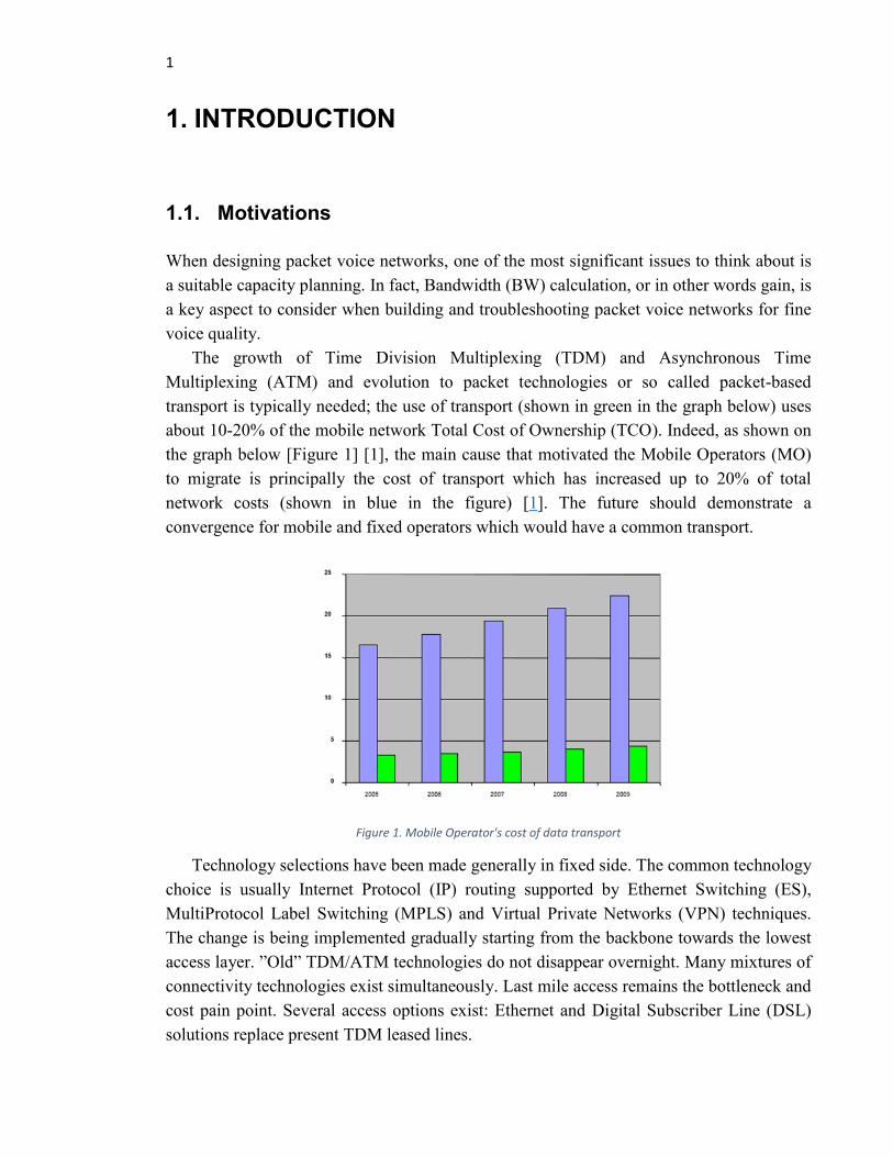
When designing packet voice networks, one of the most significant issues to think about is
a suitable capacity planning. In fact, Bandwidth (BW) calculation, or in other words gain, is
a key aspect to consider when building and troubleshooting packet voice networks for fine
voice quality.
The growth of Time Division Multiplexing (TDM) and Asynchronous Time
Multiplexing (ATM) and evolution to packet technologies or so called packet-based
transport is typically needed; the use of transport (shown in green in the graph below) uses
about 10-20% of the mobile network Total Cost of Ownership (TCO). Indeed, as shown on
the graph below [Figure 1] [1], the main cause that motivated the Mobile Operators (MO)
to migrate is principally the cost of transport which has increased up to 20% of total
network costs (shown in blue in the figure) [1]. The future should demonstrate a
convergence for mobile and fixed operators which would have a common transport.
Figure 1. Mobile Operator's cost of data transport
Technology selections have been made generally in fixed side. The common technology
choice is usually Internet Protocol (IP) routing supported by Ethernet Switching (ES),
MultiProtocol Label Switching (MPLS) and Virtual Private Networks (VPN) techniques.
The change is being implemented gradually starting from the backbone towards the lowest
access layer. ”Old” TDM/ATM technologies do not disappear overnight. Many mixtures of
connectivity technologies exist simultaneously. Last mile access remains the bottleneck and
cost pain point. Several access options exist: Ethernet and Digital Subscriber Line (DSL)
solutions replace present TDM leased lines.

2
The overall transport and networking market is growing about 8% each year. For this
reason, a wide product portfolio and system competence on packet networks is needed to
create an optimum transport solution for future mobile and converged networks.
Main research and technology challenges are system understanding, network
management, Quality of Service (QoS) traffic management and Base Transceiver Station
(BTS) synchronization.
According to the graph below [Figure 2] [1], the relative size of the mobile operator
market compared to overall market varies a lot from segment to segment [1]:
The use of microwave radios remains high in mobile operators’ own networks.
On site nodes (IP/ATM/Ethernet) about 15 to 20 %.
In (long distance) optical equipment up to ~10%.
Some segments grow especially Metro Ethernet, IP/Ethernet nodes, New
Generation-Synchronous Digital Hierarchy (NG-SDH)/ Synchronous Optical NETwork
(SONET) and Wavelength-Division Multiplexing (WDM). Others decrease such as ATM
and conventional SDH/SONET.
Figure 2. The growth of the networking market
According to Analysis Mason's Wireless network traffic worldwide: forecasts and
analysis 2013–2018, the volume of worldwide mobile data traffic reached in 2012 about 8.1
exabytes [2].
This will be explicitly illustrated in the graph below [Figure 3]. The Compound Annual
Growth Rate (CAGR), referred in the figure, is the mean annual growth rate of an
investment over a specified period of time longer than one year.
The rate of traffic growth has world widely declined. On 2011, it used to be 99% which
has dropped to become 78% in 2012 and 56% by the end of 2013, except that there were
more important distinctions at regional and country levels [2]:
In Western Europe, traffic growth was just 47% and less than 20% in recession-
hit southern European countries.

3
In Japan and South Korea, the Long Term Evolution (LTE) boom has preserved
growth rates at almost 100%.
In middle-income markets, such as Russia, the volume of traffic on data-only
services keeps on increasing considerably. These markets show gaps in
broadband infrastructure.
Figure 3. Mobile data traffic 2011–2012 and CAGR 2012–2018 (growth by region)
Data traffic produced by smart-phones is expected to dominate world widely the mobile
network even more than it does today. As illustrated in Figure 4 [3], between 2016 and
2022, total mobile traffic for all devices is more likely to increase by 8 times higher. Total
mobile data traffic is expected to rise at a CAGR of around 45%. [3]
Figure 4. Mobile data traffic (GB/month per smartphone)
Actually, Western Europe and North America have a bigger amount of total traffic than
their subscription numbers involve. This is caused by the elevated amount end-user devices
and well built-out Wideband Code Division Multiple Access (WCDMA) and LTE
networks, accompanied by reasonably priced packages of large data volumes, which makes
data usage per subscription very high.

4
Indeed, as noticed on Figure 5 below [3], between 2016 and 2022, data traffic generated
by smart-phones is expected to increase by 10 times. By the year 2022, there will be 12
times more mobile data traffic in Central & Eastern Europe and Middle East & Africa
(CEMA) [3].
Figure 5. Global mobile data traffic (ExaBytes/month)
So, as we can notice, more than 90% of mobile data traffic will be generated by smart-
phones. Indeed, in Asia Pacific, the propagation and the level of use of mobile broadband
technology vary from country to country. For instance, Japan and South Korea deployed
LTE at an early stage and markets situated for example in Singapore and Hong Kong are
vastly advanced. Whereas, in less developed countries, Global System for Mobile
communications (GSM) is still the dominant technology, which suffers from insufficient
network quality and high data subscriptions cost and mobile data consumption.
1.2. Goals and scope
New technologies such as High Speed Packet Access (HSPA), Worldwide Interoperability
for Microwave Access (WiMAX), etc., are increasing the growth of data traffic in the
operator’s access networks.
Legacy Frame Relay, TDM and ATM networks are expensive to use and operators need
more cost efficient transport network solution to carry that extra traffic between the radio
networks and the packet core sites.
For these reasons, all-IP flat architecture traffic and Ethernet interfaces in all the
network elements should be implemented in order to get a cost efficient and reliable usage
of the network. This means:

5
Meeting Radio Access Networks’ (RANs’) requirements and evolution (more
bearers BW).
Saving maintenance and management costs especially for Base Stations (BS).
Launching new services faster while ensuring QoS and cost efficiency.
Silence removal Circuit Switching (CS) voice. That will result on a very high
BW saving gain with Voice Activity Detection (VAD) based on all-IP
convergence.
Traffic multiplexing to a single packet for overhead diminution.
The possibility of header compression for Ethernet. This might not be mandatory,
since BW on Ethernet is not so critical.
Header compression for TDM. This is mandatory since the BW is critical on
TDM.
Header compression for Real Time Protocol (RTP), so called CRTP, which
reduces the possibilities of bit errors in the frame. It contains Robust Header
Compression (ROHC) (compression from 404 bytes) [4].
1.3. Thesis structure
In order to well understand the work that has been done in NSN, this thesis starts by
presenting the state of art and the rapid growth of mobile data transmission in packet-voice
networks and mainly in telephony and smart-phones’ world. It starts with a concise
presentation and comparison of new services’ fast evolution world widely that is very
costly to mobile operators in terms of network quality and bandwidth consumption. For that
reason they desire to implement all-IP flat architecture traffic and Ethernet interfaces in all
the network elements in order to get a cost efficient and reliable usage of the network.
At first, an overview of the architecture of GSM/Enhanced Data for Global Evolution
(EDGE) Radio Access Network, aka GERAN, will be given in addition to the network
elements and their interfaces. Then, the supported CODECs for voice encoding and the
effects of coding algorithms on bandwidth usage will be presented.
After that, protocols such as User Datagram Protocol (UDP), RTP, Real Time
Controlling Protocol (RTCP), etc., that are used for network communication and transport
will be briefly introduced in order to comprehend network data transmission that is
influenced by many factors such as noise, packet delay and loss, jitter, latency, etc., and
that will be explicitly presented under the chapter “voice quality aspects”.
Later on, in a separate chapter, RTP-packets multiplexing for A interface over Internet
Protocol (IP) and multiplexing negotiation via RTCP will be described. Different use cases
are presented, such as multiplexing with or without RTP header compression. During the

6
thesis work time, two scenarios are taken into consideration; Transcoding in the Base
Station Subsystem (BSS) or in the Core Network (CN).
As a conclusion, the effects of header compression and multiplexing process on the
bandwidth gain, network congestion and buffering, traffic data and header payload
escalation will be highlighted.
And for future horizons and researches, as usual, some security issues and
recommendations will be introduced and discussed briefly.
7
2. BACKGROUND
2.1. GSM /EDGE (GERAN) overview
Mobile network is very related to the key word GSM; a standard digital mobile telephony
system using a channel access method called Time Division Multiple Access (TDMA) to
ensure communications between different tenants sharing the same frequency by dividing it
into time slots (for each tenant) making simultaneous communications possible.
Nowadays, mobile devices evolved and basically all of them are connected to the
internet through the Third Generation (3G) standard and to ensure that connection, EDGE
is needed.
The standard connecting mobile devices to the internet is General Packet Radio Service
(GPRS) but the new data system EDGE appears to be three times faster than the outdated
one.
The evolution of these three aspects of mobile networking GSM, TDMA and EDGE
made the emergence of a new network combining these technologies in a single one called
GSM/EDGE Radio Access Network (GERAN) supporting real-time services through IP
interfacing using Universal Mobile Telecommunication System (UMTS). Standards for
GERAN are maintained by the 3GPP.
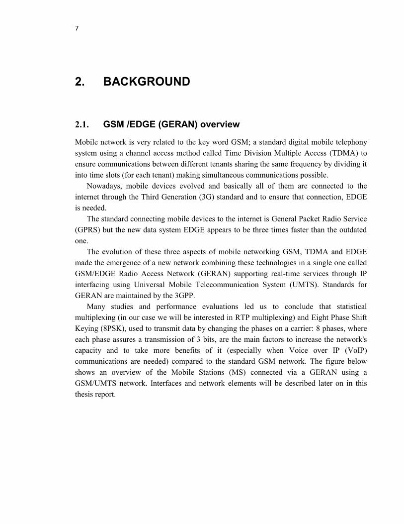
Many studies and performance evaluations led us to conclude that statistical
multiplexing (in our case we will be interested in RTP multiplexing) and Eight Phase Shift
Keying (8PSK), used to transmit data by changing the phases on a carrier: 8 phases, where
each phase assures a transmission of 3 bits, are the main factors to increase the network's
capacity and to take more benefits of it (especially when Voice over IP (VoIP)
communications are needed) compared to the standard GSM network. The figure below
shows an overview of the Mobile Stations (MS) connected via a GERAN using a
GSM/UMTS network. Interfaces and network elements will be described later on in this
thesis report.

8
Figure 6. GERAN’s main overview
GERAN is the core of a GSM network. It is the radio part of GSM/EDGE together with
the network that joins the BSs via Ater and Abis interfaces and the Base Station Controllers
(BSCs) via A interfaces, Gb etc. GERANs can be coupled with UMTS Terrestrial RAN
(UTRANs) in the case of a UMTS/GSM network.
2.1.1. Current system’s architecture
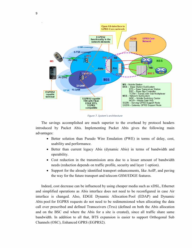
The figure below [Figure 7] describes the data flow and signals during a VoIP
communication over the GERAN network. Starting from an MS transmitting the signal to
the Base Station Subsystem (BSS) reaching the Base Transceiver Station (BTS) which is
the main component in the BSS to receive the signal from MSs by Air and transmitting it to
the BSC, the component that takes control over BTSs, in the same BSS through the Abis
interface. Then through the Ater interface, data is transmitted to the TransCoder Sub-
Multiplexer (TCSM), the component in charge to take control over many BSCs in the same
BSS. This component is basically used to compress data for more efficient tranmission
either to the Mobile Switching Center (MSC) controlling many BSSs and switching the
data received to the right MGW or directly sent to the appropriate MGW depending on the
IP address and routing protocols. Aggregation and oversubscription are possible in the
network.
9
Figure 7. System's architecture
The savings accomplished are much superior to the overhead by protocol headers
introduced by Packet Abis. Implementing Packet Abis gives the following main
advantages:
Better solution than Pseudo Wire Emulation (PWE) in terms of delay, cost,
usability and performance.
Better than current legacy Abis (dynamic Abis) in terms of bandwidth and
operability.
Cost reduction in the transmission area due to a lesser amount of bandwidth
needs (reduction depends on traffic profile, security and layer 1 option).
Support for the already identified transport enhancements, like AoIP, and paving
the way for the future transport and telecom GSM/EDGE features.
Indeed, cost decrease can be influenced by using cheaper media such as xDSL, Ethernet
and simplified operations as Abis interface does not need to be reconfigured in case Air
interface is changed. Also, EDGE Dynamic Allocation Pool (EDAP) and Dynamic
Abis pool for EGPRS requests do not need to be redimensioned when allocating the data
call over prescribed and defined Transceivers (Trxs) (defined on both the Abis allocation
and on the BSC end where the Abis for a site is created), since all traffic share same
bandwidth. In addition to all that, BTS expansion is easier to support Orthogonal Sub
Channels (OSC), Enhanced GPRS (EGPRS2).
10
So, sharing the very same bandwidth leads to a gain aggregation, as we are using only
one transport network for the operator to be maintained and to delete savings by exploiting
co-siting with other radio access technologies such as WCDMA, LTE, etc.
2.1.2. Current system’s interfaces
In the User-plane (UP), different RTP payload formats were used for different speech
CODECs. Following BSS A-interface alternatives are implemented:
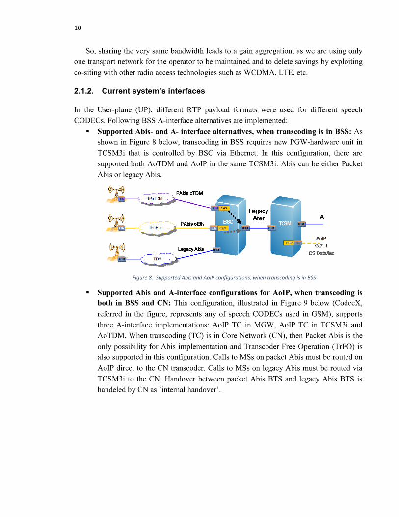
Supported Abis- and A- interface alternatives, when transcoding is in BSS: As
shown in Figure 8 below, transcoding in BSS requires new PGW-hardware unit in
TCSM3i that is controlled by BSC via Ethernet. In this configuration, there are
supported both AoTDM and AoIP in the same TCSM3i. Abis can be either Packet
Abis or legacy Abis.
Figure 8. Supported Abis and AoIP configurations, when transcoding is in BSS
Supported Abis and A-interface configurations for AoIP, when transcoding is
both in BSS and CN: This configuration, illustrated in Figure 9 below (CodecX,
referred in the figure, represents any of speech CODECs used in GSM), supports
three A-interface implementations: AoIP TC in MGW, AoIP TC in TCSM3i and
AoTDM. When transcoding (TC) is in Core Network (CN), then Packet Abis is the
only possibility for Abis implementation and Transcoder Free Operation (TrFO) is
also supported in this configuration. Calls to MSs on packet Abis must be routed on
AoIP direct to the CN transcoder. Calls to MSs on legacy Abis must be routed via
TCSM3i to the CN. Handover between packet Abis BTS and legacy Abis BTS is
handeled by CN as ’internal handover’.

11
Figure 9. Supported Abis and AoIP configurations, when transcoding is in CN
Main reasons for these alternatives are cost saving in transport, because IP-technology
is cheaper than TDM one. Also maintenance and operations cost are cheaper with IP
networks, because they are easier to configure and more flexible than TDM networks
especially when Multipoint A is used.
IP also provides flexible UP routing and network design as the backbone can be shared
between different user and Control Plane (CP) traffics. For instance, when using AoIP with
a transcoder in TCSM3i, the benefits for this configuration are providing an easier
Multipoint-A configurations and utilizing existing transcoder capacity when IP-connections
in A interface. In the case of AoIP with a transcoder in MGW, the benefits for this
configuration is a latency decrease and a support for TrFO, which improves voice quality,
because no tandem coding is needed that usually consumes much transcoding capacity in
the network.
As mentioned in the above sections, the system is using many different kinds of
interfaces. They are going to be described and defined below.
Abis interface
It is the telecommunication part that links the BSC to the BTS. Abis interface is
implemented according to recommendations in 3GPP 48.051[5], 48.052 [6] and 48.054 [7].
The Abis Operating & Management (O&M) part is a NSN proprietary and supports
additional functionalities such as remote transmission equipment management, alarm
consistency, the Site Test Monitoring (STM) unit and BTS database management.
This interface, defined in accordance with Open Systems Interconnection (OSI)
protocol model, permits the control of the radio equipment and radio frequency allocation
in the BTS. The physical interface is a Pulse Code Modulation (PCM) line. It is a digital
interface at a 2048 kbps European Telecommunications Standards Institute (ETSI) or at
1544 kbps American National Standard Institute (ANSI), based on the International
Telecommunication Union for Telecommunications sector (ITU-T) recommendation
G.703. [8]
Sub-multiplexing is used on the Abis interface as a standard solution, because each
speech channel reserves only 16 kbps (Full-Rate (FR) or DR channel) or 8 kbps (Half- Rate
channel (HR)) in the ETSI environment and 16 kbps in the ANSI one.

12
There are different transport options for the Abis interface such as over satellite and
auxiliary equipment for transporting AbisoIP can be used.
A interface
It is the interface that connects the BSS to the MSC and is implemented according to the
GSM standards. It enables information (channels, timeslots...) to be allocated to the mobile
equipment severed by the BSS. Handover must be enabled so that the messaging can be
undertaken by the interface.
Thanks to the open standardized aspect, as specified by the 3GPP, the BSS can be
utilized with any switching centers supporting the A interface. The latter is situated at the
periphery of the MSC and has a bit rate of 64 kbps per channel, but the net radio path traffic
channel is at a rate of less than 16 kbps. [9]
A transcoder, which plays the role of rate adaptation function, is needed in order to get
a rate conversion. The interface is designed in such way that transcoding may be physically
located at either the BSS or the MSC site; however the transcoder is considered to be part
of the BSS.
Ater interface
This interface is Nokia-specific. It is situated between TCSM and BSC. The physical
interface consists of one or more PCM lines. It is a BSS-internal interface with a 8 kbps, 32
kbps or 64 kbps capacity Transcoding and Rate Adaptation Unit (TRAU). [10]
TRAU is an individual block of the TCSM which converts the 64 kbps traffic channels
arriving from the MSC into channels with 16 kbps or 8 kbps rate [11]. It also multiplexes
these channels to fit into the time slots of the trunk towards the BSC. From the BSC to the
MSC, it works according to the same principle but just in reverse. One 16 kbps time slot in
the Ater interface PCM trunk is used for the TCSM O&M.
Lb interface
This interface is used to connect a Serving Mobile Location Center (SMLC) stand-alone to
a BSC. Furthermore, the Lb interface feature contains a controlling functionality for the
allocation of location requests between Position Based Services (PBS) in BSC and the
external Stand-alone SMLC.
Gb interface
This interface connects the BSS to the Serving GPRS Support Node (SGSN) in order to
transmit signaling and user data. It is used to allocate resources to users only during activity
periods and then released to other users who are multiplexed on the same BSS.
Cell Broadcast Center (CBC) interface:
It is implemented according to GSM Specification 03.41 and permits the open
interconnection between BSC and CBC. The CBC connection is made through the OMU
13
using current Q3 interface plug-in units AC25 and AS7 [12]. The CBC connection shares
the same transport media as Q3; only a new logical connection is introduced. If a non-
redundant Q3 connection is used more transmit capacity can be gained by using a dedicated
plug-in unit for the CBC.
Nb interface:
It is the interface between two MGW. It has as control protocols Session Description
Protocol (SDP) and Access Link Control Application Part (ALCAP). As UP transport
protocols, it uses RTP and RTCP.
Radio interface:
This interface is implemented according to the GSM specifications [12]. The BTS provides
the Radio interface via the air to the MS such as mobile phones.
Q3 interface:
Q3 is based on the Organization and Management (O&M) framework of the ITU-T and
The interface consists of a full seven-layer OSI protocol stack. It is located between BSC
and network service and management system (Nokia NetAct).
Q1 interface:
Q1 is a Nokia-specific interface. It is a transmission management bus that connects Nokia
NetAct with; Nokia Plesiochronous Digital Hierarchy (PDH) transmission elements,
Transmission Unit (TRU) and Hopper microwave radios. Q1 has a transfer rate of 2048
kbps [10].
2.2. Voice Encoding
Communications over wireless systems appear to be more complex than expected and
especially voice communication which has its own limitations.
Voice encoding is one of the concerns that we should focus on in order to ensure good
voice transmission in the bandwidth. Service providers are managing bandwidth, a precious
commodity in wireless systems, in order to allocate the minimum of it to the users one way
or another to ensure its availability and above all communication's quality. In order to
transmit voice communications without compromising its quality, voice encoding is
needed. Several techniques of voice encoding exist but the main two traditional ones are
waveform encoding and source encoding.
The BSC supports FR, HR and Enhanced FR (EFR) speech CODECs. Adaptive Multi
Rate (AMR) CODEC introduces a set of CODECs and an adaptive algorithm for CODEC
changes which together can provide significantly improved speech quality and more
capacity on the air interface. With AMR, it is possible to achieve very good speech quality

14
in FR mode even in low C/I conditions; or increase the speech capacity through using the
HR mode while still maintaining the quality level of calls.
2.2.1. Voice transcoder
The TCSM is one of the highly reliable modular components of the BSS with a wide range
of functions. A Nokia TCSM3i, which offers 44% more capacity than the previous product
variant, consists of up to 96 functional TCSM (BSC units), but which can be situated either
in the BSC or the MSC site. Actually, the 64 kbps traffic channels that arrive from the MSC
are converted into channels of 16 kbps sub time slots by the TCSM3i [11].
Indeed, the latter helps to minimize transmission costs, offering the latest enhancements
in voice quality with AMR Codec. It is links the BSC and the MSC via the A-interface in
order to enable a full use of network’s capacity. Thanks to sub-multiplexing in a ratio of 4:1
to fit into the sub time slots of the transmission line connected to the BSC, the reduction of
transmission costs is highest when the TCSM is located at the MSC site [11]. Also, the
number of transmission lines needed between the MSC and BSC sites is reduced.
Improvements have been made on pool management side, known as all-in-one circuit
pool, to reduce configuration work over time. This way, all the different CODECs are
supported by one pool in order to save time and cost instead of having to reconfigure each
different CODEC separately as the traffic pattern changes with time.
Transcoding functions are performed in the BSS and sub-multiplexing schemes are
provided to be used between the transcoder and the BSC. Several BSCs can share the
transcoder capacities. Transcoding modes will be detailed later below.
PCM encoder:
It is an acronym of Pulse Code Modulation. PCM is the simplest example of waveform
coding. At the repeaters site, this encoder allows perfect signal reconstruction as it
compensates for the quality reduction due to channel noise level that could corrupt the
transmitted bit stream. Its BW transmission is bigger than the original analogue signal and
that's a big disadvantage especially while using satellites and cellular mobile radio systems.
Modern Voice Encoder:
Voice communications have a rate of 64kbps [12]; this appears to be uneconomical and
impractical as the available spectrum is exceedingly limited. In a wireless coder
technology, Modern Voice Encoder utilizes perceptual irrelevancy in the speech signal by
adopting intelligent adaptive-linear prediction schemes and designing more efficient
quantization algorithm.
Linear Predictive Coders (LPC):
It is mostly used for low bit-rate speech coding and has a precise representation of the
speech spectral magnitude and simple computation. It divides the speech into two

15
independent components: LPC coefficients & LPC excitation. Mostly used when the bit-
rate really matters. e.g., 2400 bps LPC-10 voice coder used as a U.S. government standard
for encrypted telephony. [13]
Regular Pulse-Excited coder (RPE):
Early introduced in GSM network, RPE uses uniform spacing between pulses. It has a
uniformity that reduces the need to an encoder to locate pulse's position beyond the first
one then sort them as voice and unvoiced signals. When unvoiced signal detected, RPE
generates random pulses (non-periodic) corresponding to the unvoiced signal.
Code-Excited Linear Prediction (CELP):
Combining the features of traditional voice coders and the waveform matching features,
CELP is also called hybrid coder. CELP is able to produce medium-rate and low-rate
speech adequate for communication applications.
2.2.2. Voice CODECs
CODEC support is needed in different configurations and interfaces. Below [Figure 10] is
one example presenting support of codecs in different network entities in end to end call.
Different generations of the same network entities have different CODECs supported. Note
that AoTDM is also a possible alternative in both cases. These CODECs will be detailed
and explained later.
Figure 10. CODECs in different interfaces, when TC is in MGW (CODECs are examples only)
G.711:
It is one of the default standards of PCM for IP PBX vendors and Public Switched
Telephone Network (PSTN). It converts analog signal into a digital one with an output rate
of 64kbps. It is using a technology called Packet Loss Concealment that G.711 is making
the effect of dropped packets in a communication with less effect on its quality. Bandwidth
use is reduced during silent periods due to VAD technology. [14]

16
G.729:
This voice CODEC is one of the default standards of PCM for IP PBX vendors and PSTN.
It converts analog signal into a digital one with an output rate of 8kbps with 8:1
compression. The input and output contains 16-bits of PCM samples converted from or to
8kbps compressed data. [14]
G.723.1:
G723.1 is practically used for multimedia systems that incorporate Digital Signal
Processing (DSP), but its audio quality is lower than other stronger CODECs such as
G.711. It uses 16-bit PCM at 5.3 or 6.3 kbps with an input rate of 8 kHz. [15]
G.726:
G.726 is a voice CODEC (has roots in the PSTN network) that uses the Adaptive
Differential Pulse Code Modulation (ADPCM) scheme. It is an ITU standard which is
mostly utilized for international trunks to save bandwidth. It has an output rate of 32 kbps
(the defacto standard) but can be 16, 24, 32 or 40 kbps and provides nearly the same quality
as G.711. [16]
G.728:
In 1992, G.728, the ITU-T speech CODEC, was standardized. It is based on Low Delay -
Code Excited Linear Prediction (LD-CELP) algorithm. It samples at 8 kHz and compressed
bit-streams are generated with a bit-rate of 16 kbps [17]. The decoder has an inherent
Packet Loss Concealment (PLC) mechanism.
GSM:
The GSM CODEC, that can be FR or HR, was developed for telephony over GSM
networks. Each FR and HR operates on 20 ms frame of speech signals and sampled at 8
kHz. These CODECs generate compressed bit-streams with an average bit-rate of 13 kbps
(5.6 kbps for HR) [12].
To compress speech, FR uses, on one hand, Regular Pulse Excited – Long Term
Prediction – Linear Predictive Coder (RPE-LTP-LPC) technique, while on the other hand,
HR uses Vector Sum Excited Linear Prediction coder (VSELP) one. The algorithms used
by the GSM CODEC are VAD, Comfort Noise Generation (CNG) and PLC for handling
frame erasures.
GSM EFR:
GSM FR was developed to improve the low quality of GSM-FR CODEC. It is compatible
with the highest AMR mode. The E stands then for Enhanced. EFR works at 12.2 kbps and
provides wire-like quality in any noise free conditions. [12]

17
AMR-WB:
It is an ITU-T standard (G.722.2 recommendation) which is mainly used for wideband
telephony applications over 3G wireless and VoIP. AMR-WB stands for Adaptive Multi-
Rate–Wide Band. Speech signals are sampled at 16 kHz with a bit-rate varying from 6.6
kbps to 23.85 kbps in order to generate compressed bit-streams [18].
AMR-NB:
The AMR-NB stands for Adaptive Multi-Rate-Narrow Band (AMR-NB). Speech signals,
of 20ms frames each, are sampled at 8 kHz. Compressed bit-streams are generated with a
bit-rate varying from 4.75 kbps to 12.2 kbps. Compression is ensured via Algebraic Code
Excited Linear Prediction (ACELP) technique. AMR-NB provides VAD and CNG in order
to reduce the bit rate. [18]
2.2.3. Effects of coding algorithms
The choice of coding algorithm is crucial when designing any network solution that
includes voice. CODECs convert data from an analogue voice waveform to a digital flow
of information.
Quantizing is the mechanism that starts with sampling the analogue signals at regular
intervals of 125 µs (a classic value) followed by converting the measured analogue values
into an algebraic representation. The output consists of discreet blocks of information sent
at regular intervals.
The compression CODEC influences a lot on the total BW that is consumed. In fact, the
type to be used can either be preconfigured from the start or negotiated per call session.
A basic view of the bandwidth calculation process could be described as follow;
assuming that 1 packet carries 20 ms of the voice samples, then, in every second, 50 of
these samples are required to be sent out. Each sample carries an IP/UDP/RTP header
overhead of 320 bits. Hence, in each second, 16.000 header bits are sent. These protocols
will be defined in the following section. [20]
Consequently, the header information will automatically add 16 kbps to the BW
requirement for VoIP. For example, if the CODEC G.729 [19] is used, a total bandwidth of
24 kbps would be required to transmit each voice channel of 8 kbps. This is applicable for
most coding algorithms; however, it assumes that voice samples can be sent out within a 20
ms datagram. Whereas, when using coding algorithms with much smaller sampling
periods, multiple samples can be sent within each packet, which themselves can be buffered
for up to 20 ms.
However, this rule of thumb is not always valid as some algorithms do not generate
samples that can be fitted precisely into 20 ms Datagrams.

18
Formula 1. Bandwidth calculation
In Formula 1, variables are Layer2 headers and payload size. The value of latter depends
on the codec used, while the first one depends on the link layer protocol used, eg., Ethernet,
PPP, Frame Relay, HDLC, etc.
Table 1 . Example of a simple bandwidth calculation in function with the chosen CODEC
Assuming that a default packetization rate (IP bandwidth) is 50 packets/s (pps) and the
custom one is 33 pps. Based on these values, the table above [20] gives a calculation of the
BW per VoIP flow. This does not take into account Layer 2 overhead or any other possible
compression schemes, such as CRTP that will be discussed in detail later on.
Each voice coding system produces some delay that varies a lot and can reach up to 70
ms. For instance, concerning the 64 kbps PCM encoding, the delay is under 1 ms. [16]
IP, UDP and RTP headers have more or less a constant size; 20 bytes, 8 bytes and 12
bytes respectively (a total of 40 bytes of headers). Choosing for example a G.711 CODEC
at the default packetization rate, a new VoIP packet is generated every 20 ms (1 second / 50
pps). In addition to the payload size of each VoIP packet (160 bytes), the IP, UDP and RTP
headers are included. The total packet size then becomes 200 bytes in length (160 payload
+ 40 headers). Finally, in order to convert bits to bytes, a multiplication by 8 is required
which yields to 1600 bps/packet. At the end, when multiplied by the total number of pps
(50 pps), this arrives at the Layer 3 BW requirement for uncompressed G.711 VoIP with a
rate of 80 kbps [14]. This example of calculation corresponds to the first row of Table 1.
Notice that the calculation has been operated while assuming that Compressed Real-Time
Transport Protocol (CRTP) is not in use.

19
3. INTERWORKING AND TRANSPORT OVER IP
The use of VoIP services such as Tango, Skype and other voice applications is escalating
significantly which leads to have a very big amount of voice traffic on IP networks. While
IP is utilized as the most fundamental transport mode over which both UDP and TCP are in
use, VoIP system employs designated CODECs that create an output transmitted through a
networked infrastructure over the internet after having converted voice signals into digital
data forms (bits). These bits, using attribute data and timestamps accordingly, are usually
reconstructed at the destination end.
In fact, protocols are the set of policies required to ensure a working communication;
similarly in both human-based and computer-based communications. Standard protocols
reduce misunderstanding and wasted time by confusion.
Indeed, in computer communication, protocols involve three major components:
The interface providing a service to the software that is using it and defines the
rules for using a protocol.
Packet formats that define its syntax for the exchange of messages between local
and remote systems.
Procedures defining the operational rules concerning which packets can be
exchanged when.
Communication frameworks are developed out of numerous layered protocols. The idea
of layering is twofold: right off the bat, regular services can be worked in all gadgets or
subsystems, and particular services built out of these for those gadgets or subsystems that
need them; besides, the subtle elements of operation of local, or technology particular
highlights of a protocol can be concealed by one layer from the layer above it.
Packet Abis makes it possible to use a Packet Switched (PS) -based transmission of
signaling and traffic (payload) between BTS and BSC. Traditi1onal transport from
GSM/EDGE BTS to BSC has not been improved for effective transmission of bursty
information traffic, nor is it effortlessly adjusted to the inexpensive transport technologies,
such as IP and Ethernet.
Most of the gains provided by Packet Abis will also be capitalized in case of legacy
TDM networks. These networks are used also in future.
Providing Packet Abis on TDM is a smooth migration path for operators. The achieved
bandwidth saving is significant and that is due to only transferring packets that contain
20
data, compared with the previous technology that required empty timeslots to maintain a
constant bit rate. Abis bandwidth gains are achieved by:
Removing unneeded bits and header data from TRAU/PCU frames.
Savings because of shorter quiet frames.
All traffic is pooled to a similar transmission capacity (multiplexing gain).
Bandwidth required relies upon real need (no longer consistent).
Traffic multiplexing to same packets.
Header compression.
All these mentioned above, allow GSM network operators to migrate from traditional
static TDM to Packet Switched Network (PSN), and the low-cost transport of IP and
Ethernet, in a more efficient and cost effective way than with the already available solution
adopting Pseudo Wire Emulation Edge-to-Edge (PWE3) and the Circuit Emulation Service
over PSN (CESoPSN).
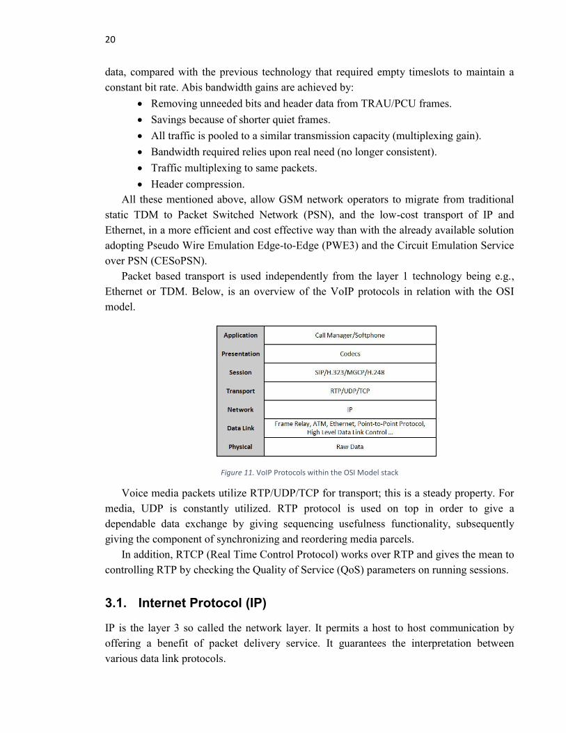
Packet based transport is used independently from the layer 1 technology being e.g.,
Ethernet or TDM. Below, is an overview of the VoIP protocols in relation with the OSI
model.
Figure 11. VoIP Protocols within the OSI Model stack
Voice media packets utilize RTP/UDP/TCP for transport; this is a steady property. For
media, UDP is constantly utilized. RTP protocol is used on top in order to give a
dependable data exchange by giving sequencing usefulness functionality, subsequently
giving the component of synchronizing and reordering media parcels.
In addition, RTCP (Real Time Control Protocol) works over RTP and gives the mean to
controlling RTP by checking the Quality of Service (QoS) parameters on running sessions.
3.1. Internet Protocol (IP)
IP is the layer 3 so called the network layer. It permits a host to host communication by
offering a benefit of packet delivery service. It guarantees the interpretation between
various data link protocols.
21
The most largely utilized variant of IP today is Internet Protocol Version 4 (IPv4). In
any case, IP Version 6 (IPv6) is likewise getting to be plainly utilized to an ever increasing
extent. The latter is used for longer addresses and in this way for the likelihood of many
more Internet clients.
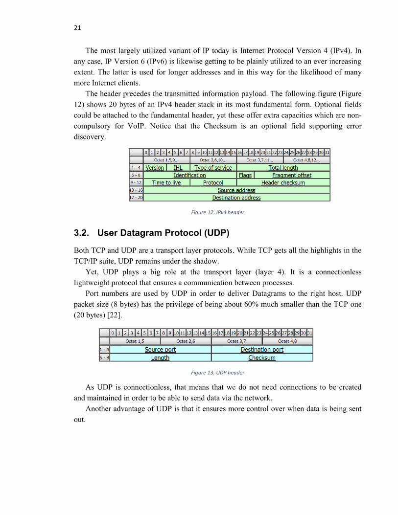
The header precedes the transmitted information payload. The following figure (Figure
12) shows 20 bytes of an IPv4 header stack in its most fundamental form. Optional fields
could be attached to the fundamental header, yet these offer extra capacities which are non-
compulsory for VoIP. Notice that the Checksum is an optional field supporting error
discovery.
Figure 12. IPv4 header
3.2. User Datagram Protocol (UDP)
Both TCP and UDP are a transport layer protocols. While TCP gets all the highlights in the
TCP/IP suite, UDP remains under the shadow.
Yet, UDP plays a big role at the transport layer (layer 4). It is a connectionless
lightweight protocol that ensures a communication between processes.
Port numbers are used by UDP in order to deliver Datagrams to the right host. UDP
packet size (8 bytes) has the privilege of being about 60% much smaller than the TCP one
(20 bytes) [22].
Figure 13. UDP header
As UDP is connectionless, that means that we do not need connections to be created
and maintained in order to be able to send data via the network.
Another advantage of UDP is that it ensures more control over when data is being sent
out.

22
3.3. Session Initiation Protocol (SIP)
SIP is an application layer signaling protocol that follows the Client-Server architecture.
SIP stands for Session Initiation Protocol and it is used for producing, altering, and ending
multimedia sessions with one or more participants.
SIP messages have a similar format to HTTP ones as they are text-based. These
messages consist of the header fields and the message body; they could either be a request
or an acknowledgment to a request. The SIP message body could either be used to point up
session requirements or to encapsulate a mixture of signaling types.
The requested resource (a unique address) must be specified in SIP messages. In fact,
these addresses follow the universal structure of HTTP addressing format such for example:
The mainly utilized messages by SIP protocol are SIP REGISTER for registering a user
with a service, and INVITE for inviting another user in a session [23].
Another important extension of SIP methods is the SIP REFER, which offers a way
where the referrer provides the referee with an arbitrary Uniform Resource Identifiers
(URI) to reference [23]. The referee will then send a SIP request (SIP INVITE) based on
the refer target (the SIP URI). As a result, many applications such as call transfer will be
allowed by the mean of SIP REFER. The refer target can use this information to decide
whether to accept the referenced request from the referee or not.
3.4. Real Time Protocol (RTP)
The RTP stands for Real-time Transport Protocol. It is used widely in communication and
entertainment systems for transporting audio and video over IP networks. Indeed, RTP has
a standardized format that allows data transfer involving streaming media, such as
telephony, video teleconference applications, television services and web-based push-to-
talk features. The RTP header, as shown in the figure below, precedes the data payload.
Figure 14. RTP header
RTP is one of the technical foundations of VoIP and is often associated with the RTP
Control Protocol (RTCP). It could be also used in combination with a signaling protocol
such as SIP in order to set up connections across the network.

23
RTP carries the media streams (e.g., audio and video), while RTCP is used to supervise
transmission statistics and quality of service (QoS) and to assist synchronization of multiple
streams.
Figure 15. Generation of RTP packets
Using the RTP protocol, as shown in the figure below, the source device (the one
sending the RTP packets) numbers and time-stamps each packet.
RTP header includes voice codec-type identification, sequence numbering and time
stamping for monitoring QoS parameters.
Packets’ retransmission is obsolete since it is useless in real-time traffic to retransmit an
expired sample of traffic.
Figure 16. Jitter-free stream of RTP packets
Numbering the packets with timestamps (based on synchronized clocks) helps the
receiving device with buffering process. Indeed, sequence numbering allows inspecting the
packet headers and smoothing jitter and delay so that voice is played continuously in a
synchronized manner.
3.5. Real Time Control Protocol (RTCP)
RTCP is transported over UDP and uses different UDP ports on each direction. Thus, it
uses a separate flow from RTP. Its purpose is to provide feedback on the quality of the
transmission link. RTCP is used by the end-users that receive the stream packets in order
to inform the sender about the stream quality, observed packet loss, delay, and jitter (fed
back to sender).

24
RTP and RTCP do not make any guarantees concerning the QoS as they do not lessen
the delay of any real time transmission. In fact, RTP just transports the digitized samples of
real time stream, whereas RTCP provides information on those samples.
In order that suitable measures can be taken to uphold or even boost the QoS,
RTCP gathers information on a given media connection that can be evaluated by special-
purpose applications. One of these measures could be for example choosing a different
compression method or even increasing the bandwidth capacity. RTCP is also used when
negotiating the use of multiplexing.
The round trip delay (RTT) could be calculated by the receiver based on a transmitted
report containing the time the information was sent.
3.6. Voice Over IP (VoIP) and A-interface over IP
A over IP (AoIP) is standardized in 3GPP. It provides A-interface, U-plane and C-plane
connections between BSS and Core Network (CN) over IP. SIGTRAN signaling is used for
the C-plane (this is standardized separately from AoIP). RTP payload formats for different
speech CODECs, CS data and fax services are used in the U-plane. Below is an overview
of a legacy architecture of VoIP and AoIP.
Figure 17. Legacy architecture of VoIP and AoIP
There are two architecture options:
1. The Transcoder function is located in the BSS (that is, the standard GSM
architecture). The Transcoder is the AoIP termination point.

25
Figure 18. Architecture for Compressed speech over IP, with transcoders in BSS
2. The Transcoder function is located in the CN (that is, the 3G network
architecture). The BSC is the AoIP termination point. At the same time, the
BSC hides the intra-BSS mobility from the CN.
Figure 19. Architecture for Compressed speech over IP, with transcoder-less BSS
26
4. VOICE QUALITY ASPECTS
4.1. Voice Quality of Service (QoS) and Mean Opinion Score (MOS)
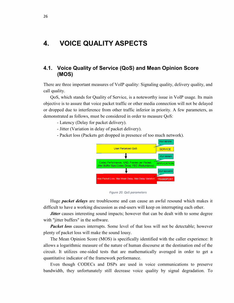
There are three important measures of VoIP quality: Signaling quality, delivery quality, and
call quality.
QoS, which stands for Quality of Service, is a noteworthy issue in VoIP usage. Its main
objective is to assure that voice packet traffic or other media connection will not be delayed
or dropped due to interference from other traffic inferior in priority. A few parameters, as
demonstrated as follows, must be considered in order to measure QoS:
- Latency (Delay for packet delivery).
- Jitter (Variation in delay of packet delivery).
- Packet loss (Packets get dropped in presence of too much network).
Figure 20. QoS parameters
Huge packet delays are troublesome and can cause an awful resound which makes it
difficult to have a working discussion as end-users will keep on interrupting each other.
Jitter causes interesting sound impacts; however that can be dealt with to some degree
with "jitter buffers" in the software.
Packet loss causes interrupts. Some level of that loss will not be detectable; however
plenty of packet loss will make the sound lousy.
The Mean Opinion Score (MOS) is specifically identified with the caller experience: It
allows a logarithmic measure of the nature of human discourse at the destination end of the
circuit. It utilizes one-sided tests that are mathematically averaged in order to get a
quantitative indicator of the framework performance.
Even though CODECs and DSPs are used in voice communications to preserve
bandwidth, they unfortunately still decrease voice quality by signal degradation. To

27
determine MOS, human interaction is needed. In fact, a number of male and female
speakers read some test sentences over the communications circuit out loud and other
listeners will rate the quality of voice. Each sentence would be evaluated by the listener
from 1 to 5; and that is how the MOS is determined. It is actually the arithmetic mean of all
the individual scores which can vary from 1 to 5, respectively worst to best. 3 is considered
to be fair and 4 as good MOS.
As an example, the G.729a CODEC can only give a MOS of about 3.9 whereas using
G.711 it can reach a score of 4.5. [24]
The table below [Table 2] shows numeric values known as the R-value resulting from
the computational E-model (will be described later). These values are relatively steady with
subjective scores.
Table 2. The ITU’s E-model and MOS scores
The R-value is defined as shown in the following equation:
Formula 2. MOS’s R-value calculation
R-value is calculated in a way that each of the factors is subtracted from the maximum
of 100. Id refers to the impairment due to the delay; Id = 0 if the absolute delay Ta is < 100
ms, and if the delay is > 100ms, we get no impairment or an increasing Id.
Below, in Table 3, is an example given by Cisco [20] showing the BW calculation
according to different CODECs used.

28
Table 3.VoIP per call bandwidth calculation and different CODECs
The payload size in a voice packet (number of bytes (or bits)) has to be a multiple of the
CODEC sample size. For instance, The G.729 packets can make use of 10, 20, 30, 40, 50,
or 60 bytes of voice payload size (either in bytes or in terms of the codec samples) [20]. A
G.729 represents 2 of 10 ms codec samples as it consists of 20 ms of voice payload size,
which corresponds to 20 bytes [ (20 bytes * 8) / (20 ms) = 8 kbps ].
So, for a single RTP (one channel only) using a G.729 CODEC (Ethernet), we get the
following estimate:
• codec (G.729) = 20 bytes/packet = 8.0 Kbps
• RTP overhead = 12 bytes/packet = 4.8 Kbps
• UDP overhead = 8 bytes/packet = 3.2 Kbps
• IP overhead = 40 bytes/packet = 16.0 Kbps
• Ethernet L2 overhead = 18 bytes/packet = 7.2 Kbps
Total = 39.2 Kbps
4.2. Quality tolerances
IP voice services’ quality can be negatively impacted mainly by transit delay and jitter.
These two parameters are inextricably knotted time-related issues. The most noticeable and
irritating about transit delay is when it exceeds 150 ms (one-way delay).
In a voice transmission, the impact of transit delay on people is basically psychological.
In fact, they have a remarkably accurate internal clock that governs the flow of a
conversation.

29
A number of testing groups have agreed on a range of [70 - 100 ms] of one-way delays
that users would find basically unnoticeable and acceptable. Once that one-way delay
exceeded the 100 ms, some people began to complain. When the delays reached 150 ms,
virtually everyone was complaining [25].
For that reason, an off-line transmission planning tool called E-model was proposed.
For a complete end-to-end voice conversation (e.g., mouth-to-ear) telephone, this tool gives
a calculation of an anticipated voice quality.
The E-model is actually easy to use. Network planners enter parameters independently
from a system in order to attain an estimation of the apparent quality. This evaluation is
represented as a numerical value between 1 and 100. Essentially, in the E-model, loss,
delay, jitters, speech coding and echo parameters are combined linearly to calculate the
resulted score.
The E-model has been popular for many years thanks to its easy form and simple linear
combination that it uses; most of the parameters are easily measurable. Below, in Table 4,
is rank of values of speech transmission quality according to this model.
Table 4. Categories of speech transmission quality according to the E-model
Notice that jitter is not explicitly integrated as an input parameter. It actually can
influence the arrival time for packets. Whereas, late real-time audio packets are comparable
to network loss or delay that are included in the model.
4.3. Quality and noise
In voice interchanges, a noise is any undesirable sound that is unwillingly added to a
coveted discourse. It happens when the sound file is converted from 16 bits to 8 bits. Sound
waves are communicated as a progression of simple sine waves. The jumble and mix of
these waves give sounds their individual attributes, making them enjoyable or repulsive to
listen which influence the nature of a VoIP communication.
There are two types of noise that are considered; the white noise and the pink noise.
The white noise consists of a sound made of human hearing’s frequency in equal
amounts. While the Pink noise, which is an alternative of white noise, is a variation of
background noise. In other words, it is a repetitive sound that has been separated to
diminish the volume at every byte. This is done to make up for the increase in the quantity
of frequencies per byte.

30
4.4. Service Level Agreement (SLA)
A Service-Level Agreement (SLA) is an agreement between a service provider and its
internal or external clients that archives what benefits the supplier will provide and
characterizes the execution guidelines and performance it is committed to meet.
A few SLA measurements to be specified are the accessibility and uptime, the
application reply time, the schedule for warning ahead of time of system changes that may
influence clients and the utilization statistics that will be given.
Besides setting up execution measurements, an SLA could include an arrangement for
catastrophes and documentation for how the service provider will compensate clients if
there should arise an occurrence of an agreement infringement. That may include incidents,
for example, catastrophic events or terrorist acts. This section is sometimes referred to as a
force majeure clause, which means to pardon the service provider from these kinds of
disasters that are outside its ability to control.
Usually, three different classes of SLA are defined; Gold, Silver and Bronze (or also,
depending on the company, Premium, Platinum and Standard). Depending on the service,
customers will enjoy one of them. Eventually, the highest of these three is the Gold level,
which is the most restrictive and demanding in their response and resolution times; it will
be prioritized over the Silver or Bronze requests. On the other hand, the Bronze level has
the least demanding response and resolution times.
Different schedules for each class can also be used:
1. Gold schedule 24h×7 days.
2. Silver 16h×7.
3. Bronze 10h×5 (from Monday to Friday for example).
4.5. Other parameters
4.5.1. Packet delay
During a conversation, when the two parties can see each other (e.g., during a face-to-face
meeting), visual signals play a significant role as the listener can see when the other party is
thinking. In any case, in a basic phone call, there are no visual signs. In that case, the
questioner must rely completely on his or her inner clock. If an answer is not given within
the expected waiting time, the questioner will either ask if the listener has heard the
question or will just repeat it.
This human response is very problematic in packet-based voice communication. In case
of an extremely lengthy delay in the transmission path (one-way delay > 150 ms), it will
trigger that subsequent inquiry response. That line up will normally slam into the reaction
originating from the opposite end (listener) which will present conversational challenges.

31
In IP telephony, the transmission delay presented in a wide region can be far more
noteworthy. The total delay a voice signal could encounter when transiting the network is
called mouth-to-ear delay. CS-voice frameworks set up negligible delays, normally under
30 ms. IP PBXs can present delays around 50-70 ms between wired stations. Given the
geographical separation and the quantity of switches included, wide region frameworks can
present delays in abundance of 100ms.
Indeed, transit delay is a combination of several factors such as voice encoding, packet
generation, WLAN connection delay, serialization delay, propagation and buffering delay
and switch/router delays.
A solution has been proposed for delay-sensitive high priority applications that involve
guaranteed bandwidth; it is called Expedited Forwarding (EF) class. It reserves a certain
minimum constant amount of bandwidth when an EF marking is added. But in case of
network congestion, non conforming packets greater than the specified priority rate are
dropped to assurance that packets in other queues belonging to different classes are not
starved of bandwidth.
4.5.2. Jitter and packet loss
Jitter is the variation in packet delay which can be measured in several ways; these
measurement calculations are defined in RFC 3550 [21] and RFC 3611 [26]. More
accurately, jitter is called also Packet Delay Variation (PDV).
According to the Internet Engineering Task Force (IETF), the jitter is by definition the
mean deviation (smoothed absolute value) of the difference in packet spacing at the
receiver compared to the sender for a pair of packets as defined in the formula below:
Formula 3. Voice jitter calculation
The jitter units are the timestamps used in the RTP packets. These units are typically the
packetization interval multiplied by the sampling rate. Considering the units Si and Ri
where Si is the sent RTP timestamp from packet i, and Ri is the received RTP timestamp for
the same packet i, then for two packets i and j (j follows i in time), D(i,j), which represents
the delay variation, may be expressed as follow:

32
Formula 4. Voice delay calculation
Jitter is low when RTP packets arrive in a steady way at regular intervals in the correct
sequence. Jitter is then all about the timing and the sequence of the arriving. In other
meaning, it is high when packets arrive scattered with gaps, out of sequence and in bursts.
In fact, jitter occurs when the RTP packet stream crosses the network (LAN, WAN or
Internet) because it has to share the same capacity with other data. The following diagram
illustrates how jitter can happen and get cumulated.
Figure 21. Jitter formation
Dedicated buffers, that the majority of VoIP end-devices have, are typically efficient
only on delay variations that are less than 100 ms. In order to compensate for network
capacity loss, once the destination end-user gets the VoIP packet, the RTP receiver process
must reestablish the timing stability such as by removing the jitter. That is actually done by
placing the packet in a buffer and then playing it out according to the RTP timestamp; it is
in fact the final part in the delay chain.
Once the source stream of RTP packets traverses the network, it becomes jittered and
arrives at the receiving end-equipment as shown in the following diagram:
Figure 22. A jittered RTP packet

33
Sequence numbering of RTP packets helps receiving end-devices to check if the
packets are still in the correct order or if any are missing. As packets could take different
routes over the network, they can get out of sequence. They can also be dropped in case of
network errors or congestion somewhere all along the transmission.
The main factor that influences VoIP perceived call quality is packet. Even 1% of loss
could be notably degrading, that’s why VoIP does not tolerate packet loss.
Figure 23. RTP packet loss
For instance, G.711 CODEC or other more compressing CODECs can accept even less
packet loss. According to Cisco, the default G.729 CODEC necessitates packet loss even
much less than 1% to avoid audible errors. Ideally for VoIP, there should be no packet loss
at all which is practically impossible to maintain all the time.
The effect of packet loss on the R-value is given by the Ie−eff term. The Ie−eff is
defined in the E-model [28] as:
Formula 5. Packet loss effect
The voice CODEC G.711 provides the best speech quality as Ie = 0 (No loss) [14]. The
advantage factor A is a value that indicates the level of users’ tolerance when using
telecommunication equipment. In other meanings, it can be seen as the readiness to trade
quality for operational convenience.
One case to consider with mobile communication is that clients could tolerate low
quality since they have the advantage of being moveable. One other case could be
considered as an advantage factor where higher delays are tolerated when utilizing a PC as
a communication mean as opposed to a phone.
Forward Error Correction (FEC) is a strong strategy for transmitting audio streams over
the IP network to diminish the impact of packet loss. In spite of the fact that this method
diminishes the impact of packet loss, it expands the bandwidth and delay in order to recover
from the lost packets.

34
4.5.3. Latency
Latency is basically a measure of the delay that callers usually can easily notice and it is
measured in milliseconds. Under 140ms, the delay is practically imperceptible to the human
ear. Somewhere close to 200ms it starts to end up noticeably observable and as the
inactivity gets more prominent, it turns out to be more apparent and more irritating [25].
There are a few potential foundations causing latency; one of which is the utilization of
substantial jitter buffers. Small delays can be also added due to the conversion between
various CODECs in addition to the technology required to join SIP to TDM (or the other
way around). Latency is impacted by packet’s type and size, QoS settings and by how
congested the framework is at any given instant. Ping command could give a rough
overview of the time delay for packets to cross the network (a round trip time delay).
4.5.4. Redundancy schemes
Duplicate packets represent similar parcels that are sent several times with a same sequence
number. Giving a duplicate packet at regular intervals of 40-100 ms is the simplest
approach. This procedure would bring to an end after getting another new valid packet
incrementing the sequence number. In a redundancy-based scheme, packets are sent with
present and previous payloads. Redundancy packets utilize an increasing sequence number
and optional payloads.
The redundancy technique is given in RFC 2198 [29]. This technique is normally
utilized for sending fax data and T.38-based fax transmission.
Duplicate packets (messages and acknowledgments) are required with one-time events.
At the collector end, once the correct packet is received, additional packets with a similar
sequence number are discarded.
4.5.5. Silence suppression, VAD and CNG
Silence suppression is a strategy generally intended to diminish transfer speed requests and
bandwidth demands so that VoIP equipments send much less RTP packets when the guest
isn't talking.
A component called Comfort Noise Generation (CNG) is utilized to supplant the
missing audio data with the goal that the receiving end could recover an appropriate
background noise. This component is characterized in RFC 3389 [30]. The source
equipment utilizes VAD to identify when the guest is talking.
Without CNG, the audience may find it extremely perturbing to just hear complete
silence when the individual at the other end of the line is quiet.
During speech pauses, audio samples are not included in the RTP packets but instead a
special instruction showing that silence started or ended is sent.

35
5. RTP MULTIPLEXING FOR A-INTERFACE OVER
IP
RTP is often used for unicast sessions despite the fact that it is fundamentally intended for
multicast ones. It runs over UDP to utilize the multiplexing and checksum services of that
protocol (illustrated in Figure 24 below). In order to support the multicast prerequisites,
RTP defines the roles of sender and receiver in addition to translator and mixer ones.
Figure 24. IP Protocol stack for the transport network User-Plane
5.1. Multiplexing features and different scenarios
Multiplexing (or muxing) is a technique of sending several streams of data or signals,
which can be either single or complex, simultaneously over a communication link.
Demuliplexing (or demuxing), on the other hand, is about recovering the separately sent
signals by the receiver.
Multiplexing VoIP packets increases payload sizes (instead of making it smaller); this
increase in payload size cuts though overhead. For instance, the combination of a VoIP
packet model of 40 bytes header with 10-30 bytes of payload causes a huge overhead. This
could be technically compacted by multiplexing the related payloads in one header.
The Multiplexing in RTCP packet indicates:
If multiplexing with(out) RTP header compression is supported;
If multiplexing with(out) RTP header compression is applied;
The local UDP port where to receive multiplexed data streams;
If a source port is requested to be added to the multiplexing header.
Figure 25. Multiplexing technique (T = Time)
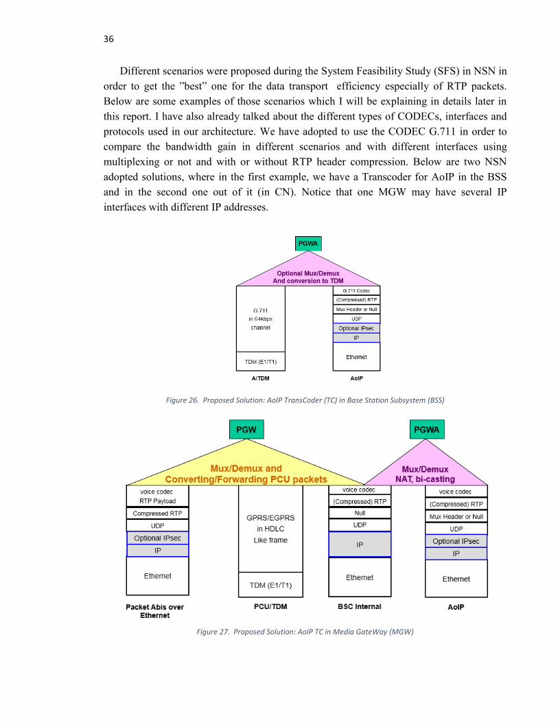
36
Different scenarios were proposed during the System Feasibility Study (SFS) in NSN in
order to get the ”best” one for the data transport efficiency especially of RTP packets.
Below are some examples of those scenarios which I will be explaining in details later in
this report. I have also already talked about the different types of CODECs, interfaces and
protocols used in our architecture. We have adopted to use the CODEC G.711 in order to
compare the bandwidth gain in different scenarios and with different interfaces using
multiplexing or not and with or without RTP header compression. Below are two NSN
adopted solutions, where in the first example, we have a Transcoder for AoIP in the BSS
and in the second one out of it (in CN). Notice that one MGW may have several IP
interfaces with different IP addresses.
Figure 26. Proposed Solution: AoIP TransCoder (TC) in Base Station Subsystem (BSS)
Figure 27. Proposed Solution: AoIP TC in Media GateWay (MGW)

37
5.1.1. Transport format for multiplexing
Either IPv4 [31] or IPv6 [32] shall be used as an RTP multiplexing network layer protocol.
The figure below shows us an overview of that protocol stack according to the OSI model:
Figure 28. Transport format
When multiplexing (with or without header compression) is applied, the UDP Protocol
[22] shall be used. Thus, in one hand, the UDP source port number shall indicate the local
end utilized to mix the multiplexed packet and, on the other hand, the UDP destination port
number shall indicate the remote port number where Protocol Data Units (PDUs) are de-
multiplexed. The MGW might apply multiplexing by transferring all packets of the UP-
connection in the direction of the agreed destination UDP port in case of successful
negotiation for an Nb UP-connection.
The figure below shows roughly how multiplexing and de-multiplexing processes are
done:
Figure 29. Muxing/demuxing process
In order to improve the BW usage in a VoIP network, three key procedures are
implemented; header compression/suppression, (could be with coalescing, prioritization or
aggregation), packet header reduction, and silence suppression.

38
5.1.2. Transport without RTP header compression
A shared media makes it is feasible for any network device to communicate with any other
one without having to set aside a connection for each pair. Multiplexing helps on limiting
and lessening the supplementary costs (less overhead) such for example to send many
signals down each cable or mobile network connection running between main urban areas,
or across one satellite uplink.
The figure below shows how the header overhead can be reduced thanks to
multiplexing procedure:
Figure 30. Reducing header overhead by packet multiplexing
NbFP stands for NetBIOS Protocol. It is in fact a non routable network and transport
level data protocol used most commonly in the 1990’s by the layers of Microsoft Windows
Networking. It is also called as NetBIOS over IEEE 802.2 LLC and incorrectly referred as
NetBEUI [33].
Actually, NbF Protocol makes large use of broadcast messages while it consumes a
small number of network resources in a very small network. Broadcasts begin to negatively
impact the performance and speed when the amount of the network users grows.
Numerous RTP/NbFP/CODEC payload PDUs, which are sent to the same IP address
are multiplexed within one single UDP/IP packet over the Nb interface between MGWs
that have already agreed beforehand about multiplexing. Only RTP packets shall be
multiplexed while RTCP shall be transported by UDP/IP packets.
Ahead of every multiplexed RTP/NbFP/CODEC payload PDU, a multiplex header,
which spots the multiplexed packet, shall be included into the UDP/IP packet. Below is an
example of UDP/IP packet format without CRTP:

39
Figure 31. UDP/IP Packet with multiplexed RTP/NbFP payload PDUs without CRTP header
It is the role of data link layer protocol to define the maximum frame size (limit the
number of packets being multiplexed) and not the multiplexing method. For example, the
maximum length of an IP datagram is of 65 535 bytes while the Ethernet one consists of 1
518 bytes. During the transit over the network, packets should not be delayed more than 1
ms to 2 ms in order to stay away from additional delay. This in reality limits a lot the
amount of multiplexed packets and lows down the multiplexing-jitter.
5.1.3. Transport with RTP header compression
Considering small media samples over low rate links such as in domestic and small offices,
the IP, UDP and RTP control information adds up a considerable overhead. It is usually
operational by the user dialing up their Internet Service Provider (ISP) at a few tens of
kbps.
In IPv4, an IP datagram has a header size of 20 bytes [31] compared to 40 bytes in IPv6
[32] and 8 bytes for UDP header [22]. So, for a single little sample of 20 ms worth of 8 kHz
speech, the RTP header adds 12 bytes, making a total of 40 bytes of control; compressed
payload, RTP, UDP, and IP header combinations are called VoIP packets.
The following example gives us a simple calculation of the bit-rate:

40
For this reason, the RTP header may be optionally compressed in order to attain even an
enhanced bandwidth savings. This is achievable since the RTP header includes many fixed
fields that stay put during an RTP session if NbFP is used as payload.
Figure 32. UDP/IP Packet with multiplexed RTP/NbFP payload PDUs with CRTP header
MGWs are in charge about the negotiation of the RTP header compression use. For
each RTP session, at least the first two RTP packets are sent with their full RTP header to
let the receiver stock up the full header and employ it later on for decompression. This
procedure is done till reception of an RTCP packet from the peer indicating RTP header
compression support. Subsequent packets may be sent with a compressed RTP header.
The frame, which is used in voice compression, is a basic small block of samples. In
G.729a, the basic frame size is 10 ms (80 samples) [19], whereas in G.723.1, it consists of
30 ms (240 samples) [15]. Voice payload could use a group of compressed frames, called
also VoIP voice raw payload or VoIP packet payload, that can reach a size up to 80 ms. An
IP packet consisting of IP, UDP, RTP, and compressed voice payload is pointed up in the
following figure. After being encapsulated with many other headers, these payload and
VoIP headers are delivered through physical interfaces such as Ethernet, DSL, and cable.

41
Figure 33. Transport with RTP header compression
RTP header compression, aka CRTP, follows a hop-by-hop method; all the devices that
are concerned within the transmission pathway ought to be conventional to this scheme.
Details on CRTP can be found in RFC 2508 [34].
Figure 34. Comparison of IP/RTP packets’ size before and after header compression
As illustrated on figure below, after applying a CRTP, the IP/UDP/RTP header in an
RTP data packet is compacted from 40 bytes to roughly 2 - 5 bytes.
Figure 35. Packet size reduction after header compression
5.1.4. Multiplexing negotiation via RTCP
For each UP-connection, RTCP (RFC 3550) [21] shall be utilized independently and
transported by UDP/IP packets.
RTCP may be used at the Nb interface with Bearer-Independent Call Control (BICC)
signaling and the Iu interface according to 3GPP TS 29.414 [35] and 3GPP TS 25.414 [36].

42
The RTCP utilization is recommended according to RFC 3550 [21] and optional only
on the Nb interface, which makes it applicable in almost all scenarios of interest. Indeed,
RTCP is the only carrier signaling protocol, including a SIP-I based 3GPP Cs domain, and
the Iu interface.
RTCP permits application specific new packet types’ addition (defined by 3GPP) that
may be added to compound RTCP packets transferred within RTCP messages. This
addition might need IANA registration.
The contents of new Multiplexing RTCP packets are proposed as follow:
The support of multiplexing without RTP header compression.
The support of multiplexing with RTP header compression.
Indication if multiplexing is selected.
The local UDP port number where to receive multiplexed data streams.
The encoding shown in Figure 36 is suggested for this RTCP packet:
Figure 36. RTCP Multiplexing packet
The APP packet header includes:

43
The application-dependent data encloses a multiplexing bit (MUX) that indicates
whether multiplexing without CRTP is supported (set to 1) or not (set to 0) by the sender of
the RTCP packet. It also has a CP field (1 bit) that specifies if multiplexing with CRTP is
supported (set to 1) or not (set to 0) by the sender of the RTCP packet.
It encloses as well Selection bits (2 bits) that specify if multiplexing with or without
header compression for the UP-packets is applied by the sender of the RTCP packet or not.
The following values are defined:
Local MUX UDP port (15 bits) where the sender demands to collect muxed data
streams without CRTP (MUX =1). The value shall be the same as the local MUX
UDP port divided by two. In case of MUX and CP bits = 0 is, the receiver of the
RTCP multiplexing packet should ignore it.
Reserved bits (set to 0 in sent RTCP multiplexing packet) represent extension
bits that may be added in future releases of the RTCP multiplexing packet.
Reserved bits shall be ignored in incoming RTCP multiplexing packets.
Multiplexing is not applied from the beginning when setting up a new UP-connection.
In fact, both MGW peers initiate sending data without applying any multiplexing. In order
to indicate their readiness to receive multiplexed data streams, they include the new RTCP
multiplexing package in the initial one (at the very beginning of the RTP session) and all
subsequent RTCP packets they send to be able to apply multiplexing as soon as possible.
For a given RTP session and in all the sent RTCP multiplexing packets, a MGW shall at
all times proclaim the same multiplexing capabilities and the same UDP port (single one
per destination IP address) where to receive multiplexed data streams.
When a MGW gets an RTCP packet that contains the corresponding UDP multiplexing
port, it can decide whether to apply multiplexing to send the related RTP data streams
towards the sender or not. If it decides to apply multiplexing, it shall indicate in subsequent
RTCP multiplexing packets if multiplexing occurs with or without header compression then
sending multiplexed data streams can immediately start. The peer´s decision time to apply
multiplexing or not could be useful information for the receiver in order to be able to
estimate traffic loads.
According to RTCP procedures, if a MGW does not support multiplexing, does not
receive RTCP or gets RTCP without the multiplexing package, shall carry on sending data
without applying multiplexing.

44
Notice that if a MGW sends an RTCP multiplexing packet indicating the willingness to
receive multiplexed data streams, it does not automatically mean the other way around. In
other meanings, its readiness to send multiplexed data streams. Multiplexing may be
applied on a single direction for a given RTP session.
Some restrained features of this method are that user connections are transmitted
without multiplexing until reception of the first RTCP package. As a result, total
multiplexing gain will be reduced by about 2%.
5.2. Multiplexing effects on bandwidth gain
The major intention of VoIP packet multiplexing methods is to improve network bandwidth
utilization. Multiplexing methods accomplish this aim in numerous aspects. First, on the
one hand, the typical VoIP packet payload size between 10 and 30 bytes depends on the
CODEC. On the other hand, up to 104 bytes header is added to each payload. Accordingly,
the header overhead, which is the relative ratio between the header size and the packet size,
is around 77.5% to 92%.
The figure below shows the header overhead with different payload sizes.
Figure 37. Header overhead ratio without multiplexing
When multiplexing several packets in one header, the header overhead decreases
depending on the number of multiplexed packets in the mux-pkt, as shown in the following
figure:
Figure 38. Header overhead ratio with multiplexing

45
All the above-mentioned factors (header overhead, delay of each packet, and capacity)
reflect the bandwidth utilization. On the basis of these factors, multiplexing methods highly
improve bandwidth utilization. The following figure shows how the capacity with packet
multiplexing is greater than the capacity without multiplexing.
Figure 39. Number of calls with and without multiplexing
Actually, BW enhancement, particularly with regards to VoIP frameworks is an urgent
need. Faced by an astoundingly competitive data and VoIP industry experience, as well as
the truth of declining incomes for voice services per user, service providers and
communication operators, such for example, NSN Oy, are searching for arrangements that
can bring down the chances while in the meantime placing them in a more grounded,
achievement empowering position. There are so much reasons and means from which these
organizations require and can profit from optimization. To begin with, 40% of most VoIP
packets are headers that are mainly constant during a transmission, which causes
redundancy. Actually, these redundancies proceed with call frequencies notwithstanding
similitudes in source and (or) destination IP addresses, with no arrangement for sharing.
Ineffective real-time streams like standard VoIP applications such as Skype and smaller
packet application that do not use full frame video streaming, do necessitate management
and prioritization for efficient quality-size tuning, for least impact and quality
improvement.
Multiple RTP/NbFP/CODEC payload PDUs of different UP-connections within one
packet could be transported simultaneously thanks to an optional transport format that has
been specified in 3GPP Rel-7 [37]for the Nb interface and IP transport. The use of this
transport format saves significant bandwidth in the IP network, as shown below,
(bandwidth gains are evaluated in 3GPP TR 29.814) [38].
Table 5. Bandwidths with AMR 12.2 (60 % activity factor) with/out multiplexing (2 or 10 RTP frames, common IP/UDP header) with CRTP header

46
5.2.1. Buffering and Packet Delay Variation (PDV)
Asynchronous packet arrivals are transformed into a synchronous stream by the mean of
jitter buffers, called also playout buffers. The transformation is assured by changing
variable network delays into constant ones at the target end-systems.
The main function of the jitter buffer is to trade off between packet delay and the
possibility of interfered (out-of-order) playout due to late packets that would be discarded.
The network’s characteristics could face some needless constraints if the payload buffer
is set either randomly huge or small. In one hand, if the jitter buffer is set too large, it
means that less delay budget is offered to the network. On the other hand, if it is set too
small network jitter would be accommodated and the buffer either underflows or overflows.
In case of buffer underflow, when the CODEC desires to play out a sample, the buffer
would be empty. Whereas, in the other case of buffer overflow, next arriving packet will
not be able to access the queue as the jitter buffer would already. Both cases cause voice
quality degradation.
In order to surmount these issues, a solution called adaptive jitter buffers has been
proposed. This solution intends to tune dynamically the jitter buffer’s size to the smallest
tolerable value. Well-designed adaptive payload buffer algorithms should not inflict any
pointless restrictions on the network design by doing as follows:
Immediately incrementing the payload buffer size to the present calculated jitter
value following a payload buffer overflow.
Gradually decrementing the payload buffer size when the calculated jitter is
smaller than the present payload buffer size.
PLC use in order to interrupt the loss of a packet in case of a payload buffer
underflow.
Theoretically, worst-case per-hop delays could be engineered out explicitly when such
adaptive jitter buffers are used; based on maximum and minimum per-hop delays. Indeed,
when designing network-specific recommendations for jitter, advanced formulas can be
utilized. Moreover, extensive lab testing has revealed that voice quality degrades
considerably when jitter constantly surpasses 30 ms, this value can be considered as a jitter
goal.
Usually, VoIP packets are buffered at the receiving end-user with the aim of balancing
inconsistent network delay. The recipient buffer sizes can either be invariable or adaptively
accustomed.
One of the main difficult tasks in VoIP networks is keeping the delay as low as feasible,
and avoiding excessive packet losses simultaneously. One among the possible solutions is
to use the adaptive algorithm that can achieve a lower rate of lost packets.

47
Adaptive playout delay can be either per-talk spurt where the delay remains steady
throughout the talk spurt and the regulations are made between talk spurts, or per-packet
based but that would add spaces in speech, and thus not recommended for VoIP.
5.2.2. Multiplexing wait time and effects on users’ satisfaction
During the internship that has come to an end at NSN Oy, many use cases have been gone
through and many scenarios have been proposed. Some of these scenarios have been taken
into account, according to the end-user’s satisfaction about the QoS, and some others were
just dropped and ignored. The diagram below (Figure 40) shows an overview of the final
user’s satisfaction in function with the voice delay according to the E-model:
Figure 40. Delay estimation use cases and end-user satisfaction
Notice that the total end delay depends a lot on the CODEC used. Presently, the current
use case (north) shows a total RTT of about 200 – 230 ms for a mobile terminated call. In
worst case scenario, where we have packet Abis over Ethernet, the RTT reaches 370 ms.
Many other cases and delay calculations are presented in Table 7 in the appendix section
(colors in the table correspond to the ones in E-model of Figure 40).
Assumptions in the Figure to be taken into account are:
5 ms EF Gold service assumed (average delay < 5 ms)
10 ms average buffering (DownLink (DL) – BTS) 10 ms assumed (0 - 20 ms
possible).
10 ms average UpLink delay due to scheduling (0 - 20 ms).
20 ms transcoder needed time.
1 ms jitter (PDV) of PSN (<<20 ms) assumed.
0.5 ms CC latency assumed.
0.5 ms TDM delay assumed due to CC or Mixed Media Router.

48
15 ms PS data average delay due to bursty traffic since all sectors are
synchronized.
0.2 ms scheduling delay of L2 switch in Tx direction is assumed.
0 – 120 ms A interface is TDM in all scenarios.
8 frames per packet in PWE.
No GW functionality is required in BSC or CN.
Notice that Service Class Mapper (SCM) is used according to the different QoS
(DiffServ) model. It offers 4 different classes; Conversational Class (CC), Streaming Class
(SC), Interactive Class (IC) and Background Class (BC).
Based on the payload calculations shown on section 4.1, the figure below demonstrates
how multiplexing could save efficiently the bandwidth:
Figure 41. Payload comparison on Number of RTP Channels (G.729)
As noticed above, with 10 channels, there is a 58.4% of bandwidth savings. Indeed, at
100 channels in this same model, RTP is at 3.92 Mbps and Muxed RTP is at 1.38 Mbps. As
a result, we get a 35.4% of the RTP bandwidth usage which gives an almost 2/3 of savings.

49
6. CONCLUSION
The wide use of smart mobile devices and web applications has obviously augmented the
amount of data traffic transmitted in the network. For that reason, network sharing feature
will persist in being adopted due to high levels of up-front investment needed. Thus,
network capacity and high physical connectivity will always remain a challenge. All of
these constraints represent an exclusive business chance for network operators who will
continuously look for new transport solutions to transport high QoS at optimal cost.
Indeed, the exceptional uniqueness of making voice calls over an IP network has
encouraged end-users and service providers to migrate their habitual telecommunication
systems to VoIP ones.
Ineffective bandwidth exploitation is one of the biggest problems that delays VoIP
packets’ propagation over the network. One of the most important methods for managing
bandwidth utilization problems is packet multiplexing, which combines several VoIP
packets in one header. During this work, we made a feasibility study of VoIP packets’
multiplexing over the A-interface in GERAN with and without RTP header compression.
Depending on the CODEC applied, the bandwidth gain differs. Therefore, this study
provided a detailed investigation of multiplexing methods and different calculations have
been given in details in the appendix section. This study has also provided a lucid
understanding of the bandwidth utilization dilemma, strategies for optimizations, and
directions for future research.
So, as mentioned above, one of the methods for improving VoIP bandwidth utilization
is header compression. IP/UDP/RTP headers, in some compression techniques, could be
successfully compressed from 40 bytes to 2 bytes. This elevated compression could be
achieved when utilizing the duplicated fields in the IP/UDP/RTP headers of the successive
packets. In some multiplexing techniques, numerous VoIP packets are combined within the
mux-pkt, each with separate IP/UDP/RTP headers. Nevertheless, some multiplexing
techniques can be developed such as the one based on the redundant fields in the
IP/UDP/RTP headers within the mux-pkt.
Even though the outcome of these techniques is very positive, when using the header
compression mechanism, some downsides will occur. Whilst the baseline case was nearly
errorless, when packet lost exceeds three times in a row, bursts of errors is detected in some
sessions. In fact, in the compressed MUX case, users’ contentment will diminish. These
error bursts are originated by a sequence of multiple decompression errors. It actually
happens when the decompressor is not capable of processing a header properly; it starts

50
dropping all the frames incoming from the same session until a reception of a full header.
Consequently, according to some studies, the compression fraction should be controlled in
order not to exceed 2/10. This means, during a VoIP communication session on the same
path between two peers, 10 compressed headers (using CRTP) would follow 2
uncompressed ones [39]. Even though augmenting the ratio would reduce the overall frame
error rate, but at the decompression side, error bursts amplify.
Moreover, regardless the stream characteristics, processing errors (routers’ processing
time), queuing and decompressing cause delays, which can vary from 20 ms up to 1000 ms.
From a routing angle, the pathway that presents the smallest delay is preferred. Thus,
calculating the shortest path is not always obvious.
Definitely, numerous concerns limit VoIP packets from reaching the final destination in
real-time with zero errors, delays and/or loss. First, multiplexing degrades the QoS of VoIP.
Actually, delay, jitter, and packet loss will augment in case of an inappropriate multiplexing
method. Second, in the case of smaller amount of packets (few calls) to be multiplexed, the
bandwidth exploitation is inefficient. Third, in order to remove the traffic prioritization
aspect, multiplexing several packets from multiple streams necessitate on having the same
QoS to all streams. Finally, overhead gets higher when using multiplexing/de-multiplexing
technique. Nevertheless, even though it remains a challenge for researchers, opting for the
appropriate criterion when designing a multiplexing scheme will make it easier to improve
bandwidth usage.
Availability, reliability, confidentiality and integrity are trivial constraints in VoIP
systems. That is why its commercial deployment requires a minimum of security
mechanisms to be assured. One of the leading signaling protocols in VoIP to be considered
is SIP. Yet, this protocol is also faced to some vulnerabilities (Internet attacks), which
introduces new security problems to VoIP networks.
The application layer signaling protocol H.235, that is designed to support multimedia
over IP for Web-based video conferencing, is one of the solutions that can enhance VoIP
security [40]. Whereas, at the transport layer, Secure Sockets Layer (SSL) and Transport
Layer Security (TLS) could be deployed. IPsec, VPN and MPLS are offered at the network.
Actually, H.323 deals with some of SIP's call-handling concerns, for instance to avoid
call interruptions, it has the ability to reroute calls around failed gateways. It is though a
costly service that comes with an extra overhead which could influence the QoS. SSL
could be used under certain circumstances.
As RTP is a network independent protocol, IPsec will not solve authentication problems
for other technologies. Denial of Services (DoS) can be easily performed using
Synchronization Source (SSRC) that identifies RTP session’s participants. Moreover,
RTCP reports are not encrypted (unauthenticated), it is possible to reduce QoS by injecting
forged reception reports to RTP sessions (producing poorer sound quality with reports
indicating huge packet losses).

51
So, in addition to these protocols mentioned above, a security mechanism for
compressed RTP header, aka Secure RTP (SRTP), could be used for message encryption
and authentication as only the payload portion of the VoIP packet would be encrypted for
compression performance. Hence, the encryption does not cause transmission overhead (at
Tx units), but it causes a significant performance loss (packet padding).
Finally, as a conclusion, a good compromise between low cost technologies with high
security level, compression ratio, multiplexing technique and an optimized bandwidth
usage gain should be well defined and audited by technology designers and service
providers in order to reach a certain level of voice QoS and end-users’ satisfaction.

52
REFERENCES
[1] NEC, «Mobile Backhaul Evolution and Convergence», January 2010, E-seminar white
paper, pp.8-9, Available: https://www.telecomasia.net/content/mobile-backhaul-evolution-
and-convergence, Accessed 2015-04-20.
[2] Rupert, W., Analysis Mason, «Wireless network traffic 2010-2015», October 2013,
Available: http://www.analysysmason.com/People/Rupert-Wood/, Accessed 2012-11-12.
[3] Ericsson, «Future mobile data usage and traffic growth», 2013, Available:
https://www.ericsson.com/en/mobility-report/future-mobile-data-usage-and-traffic-growth,
Accessed 2017-11-01.
[4] EFFNET AB, «The Concept of Robust Header Compression, ROHC, Bromma», white
paper, 2004, Available:
http://www.effnet.com/pdf/Whitepaper_Robust_Header_Compression.pdf, Accessed 2017-
12-02.
[5] 3GPP TS 48.051, «Digital cellular telecommunications system (Phase 2+); Base Station
Controller - Base Transceiver Station (BSC-BTS) interface; General aspects», (version
10.0.0 Release 10), April 2011.
[6] 3GPP TS 48.052, «Technical Specification Group GSM EDGE Radio Access Network;
Base Station Controller - Base Transceiver Station (BSC-BTS) interface; Interface
principles», (Release 8), December 2008.
[7] 3GPP TS 48.054, «Digital cellular telecommunications system (Phase 2+); Base Station
Controller - Base Transceiver Station (BSC - BTS) interface; Layer 1 structure of physical
circuits», (version 12.0.0 Release 12), September 2014.
[8] ITU-T, «Recommendation G.703: Physical/electrical characteristics of hierarchical
digital interfaces», November 2001.
[9] 3GPP TR 43.903/ETSI TR 143 903, «Digital cellular telecommunications system
(Phase 2+); A-interface over IP study (AINTIP)», (version 8.3.0 Release 8), February 2009.
[10] NOKIA, «Nokia Base Station Subsystem Description», Nokia BSS Product
Documentation (Internal document), October 2014.
[11] NSN, «Transcoder Submultiplexer (TCSM3i)», Telecom NSN Essay (Internal
document).
[12] GSM 03.41 Telecommunication Specification, «Digital cellular telecommunications
system (Phase 2+); Technical realization of Short Message Service Cell Broadcast
(SMSCB) », version 5.3.0, November 2011.
[13] Nimrod, P., «Linear Prediction Coding», March 2009, Available:
http://cs.haifa.ac.il/~nimrod/Compression/Speech/S4LinearPredictionCoding2009.pdf,
Accessed 2017-12-20.

53
[14] ITU-T, «Recommendation G.711: Pulse Code Modulation (PCM) of voice
frequencies», March 2011.
[15] ITU-T, «G.723.1: Dual rate speech coder for multimedia communications transmitting
at 5.3 and 6.3 kbit/s», March 1996.
[16] ITU-T, «G.726: 40, 32, 24, 16 kbit/s Adaptive Differential Pulse Code Modulation
(ADPCM)» , 1990.
[17] ITU-T, «G.728: Coding of speech at 16 kbit/s using low-delay code excited linear
prediction », September 1992.
[18] ITU-T, «G.722.2: Wideband coding of speech at around 16 kbit/s using Adaptive
Multi-Rate Wideband (AMR-WB) », July 2003.
[19] ITU-T, «G.729: Coding of speech at 8 kbit/s using conjugate-structure algebraic-code-
excited linear prediction (CS-ACELP)», June 2012.
[20] Cisco, «Voice Over IP - Per Call Bandwidth Consumption», April 2016, Available:
https://www.cisco.com/c/en/us/support/docs/voice/voice-quality/7934-bwidth-
consume.html, Accessed 2017-12-22.
[21] IETF RFC 3550, «RTP: A Transport Protocol for Real-Time Applications», July 2003.
[22] IETF RFC 768, «User Datagram Protocol», Aug 1980.
[23] IETF RFC 3261, «SIP: Session Initiation Protocol», June 2002, July 2016.
[24] ITU-T, «P.800.1: Mean opinion score (MOS) terminology».
[25] ITU-T, «The E-model: a computational model for use in transmission planning», June
2016.
[26] IETF RFC 3611, «RTP Control Protocol Extended Reports (RTCP XR)», November
2003.
[27] ITU-T, «G.114: One-way transmission time», May 2003.
[28] ITU-T, «G.113: Provisional planning values for the equipment impairment factor Ie
and packet-loss robustness factor Bpl», November 2007.
[29] IETF RFC 2198, «RTP Payload for Redundant Audio Data», September 1997.
[30] IETF RFC 3389, «Real-time Transport Protocol (RTP) Payload for Comfort Noise
(CN)», September 2002.
[31] IETF RFC 791, «Internet Protocol», Darpa Internet Program Protocol Specification»,
September 1981.
[32] IETF RFC 2460, «Internet Protocol, Version 6 (IPv6) Specification».
[33] The free dictionary by Farlex, «NetBIOS Frames Protocol», December 1998,
Available: http://encyclopedia.thefreedictionary.com/NetBIOS+Frames+Protocol,
Accessed: 2017-10-12.
[34] IETF RFC 2508, «Compressing IP/UDP/RTP Headers for Low-Speed Serial Links»,
February 1999.
[35] 3GPP TS 29.414, «Technical Specification Group Core Network; Core Network Nb
Data Transport and Transport Signalling», (V2.0.0 Release 4), January 2001.

54
[36] 3GPP TS 25.414, «Universal Mobile Telecommunications System (UMTS); UTRAN
Iu interface data transport and transport signalling», (V 10.1.0 Release 10), July 2011.
[37] 3GPP UMTS Specification Rel-7.
[38] 3GPP TR 29.814, «Technical Specification Group Core Networks and Terminals
Feasibility Study on Bandwidth Savings at Nb Interface with IP transport», (V7.1.0 Release
7), June 2006.
[39] Franck, C., Laurent, F., Joan, V., «Optimization Of Voice Services On Hybrid LTE
And Satellite Networks», White paper, pp.6-7, Available: https://portail.telecom-
bretagne.eu/publi/public/fic_download.jsp?id=64411, Accessed 2017-12-01.
[40] ITU-T, «Implementors Guide for H.235 V3: "Security and encryption for H-series
(H.323 and other H.245-based) multimedia terminals», August 2005.

APPENDIX
Figure 42. Voice delay (total RTT) estimation 1/2
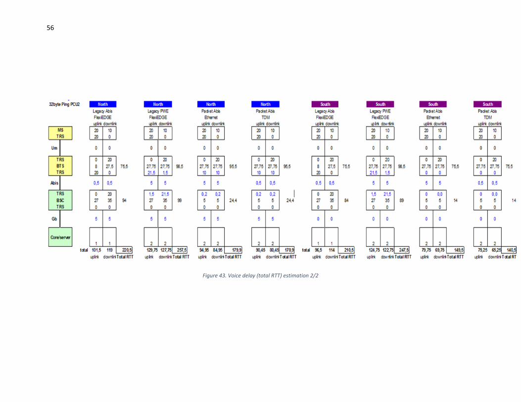
56
Figure 43. Voice delay (total RTT) estimation 2/2
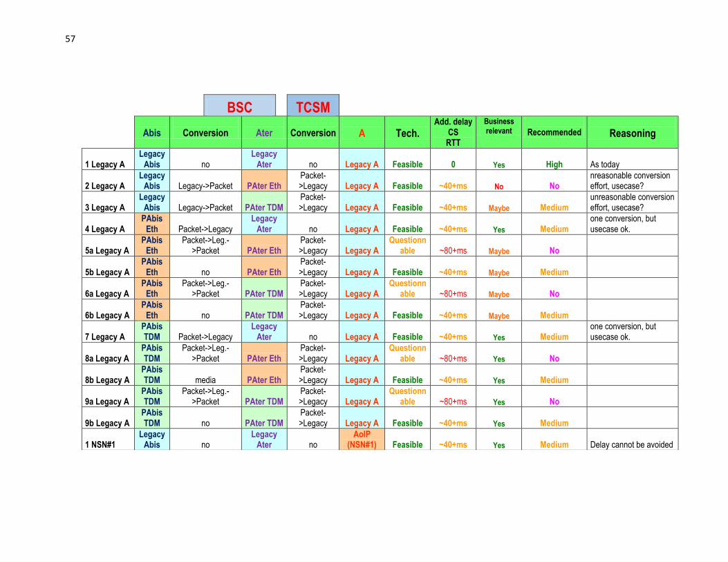
57
BSC
TCSM
Abis
Conversion
Ater
Conversion
A
Tech. Add. delay
CS RTT
Business relevant
Recommended
Reasoning
1 Legacy A Legacy
Abis no Legacy
Ater no Legacy A Feasible 0 Yes High As today
2 Legacy A Legacy
Abis Legacy->Packet PAter Eth Packet->Legacy Legacy A Feasible ~40+ms No No
nreasonable conversion effort, usecase?
3 Legacy A Legacy
Abis Legacy->Packet PAter TDM Packet->Legacy Legacy A Feasible ~40+ms Maybe Medium
unreasonable conversion effort, usecase?
4 Legacy A PAbis
Eth Packet->Legacy Legacy
Ater no Legacy A Feasible ~40+ms Yes Medium one conversion, but usecase ok.
5a Legacy A PAbis
Eth Packet->Leg.-
>Packet PAter Eth Packet->Legacy Legacy A
Questionnable ~80+ms Maybe No
5b Legacy A PAbis
Eth no PAter Eth Packet->Legacy Legacy A Feasible ~40+ms Maybe Medium
6a Legacy A PAbis
Eth Packet->Leg.-
>Packet PAter TDM Packet->Legacy Legacy A
Questionnable ~80+ms Maybe No
6b Legacy A PAbis
Eth no PAter TDM Packet->Legacy Legacy A Feasible ~40+ms Maybe Medium
7 Legacy A PAbis TDM Packet->Legacy
Legacy Ater no Legacy A Feasible ~40+ms Yes Medium
one conversion, but usecase ok.
8a Legacy A PAbis TDM
Packet->Leg.->Packet PAter Eth
Packet->Legacy Legacy A
Questionnable ~80+ms Yes No
8b Legacy A PAbis TDM media PAter Eth
Packet->Legacy Legacy A Feasible ~40+ms Yes Medium
9a Legacy A PAbis TDM
Packet->Leg.->Packet PAter TDM
Packet->Legacy Legacy A
Questionnable ~80+ms Yes No
9b Legacy A PAbis TDM no PAter TDM
Packet->Legacy Legacy A Feasible ~40+ms Yes Medium
1 NSN#1 Legacy
Abis no Legacy
Ater no AoIP
(NSN#1) Feasible ~40+ms Yes Medium Delay cannot be avoided

58
Table 6. Feasibility study and comparison of additional delays in BSC and TCSM in different scenarios with different interfaces
2 NSN#1 Legacy
Abis Legacy->Packet PAter Eth Packet->Legacy
AoIP (NSN#1)
Questionnable ~80+ms No No
3 NSN#1 Legacy
Abis Legacy->Packet PAter TDM Packet->Legacy
AoIP (NSN#1)
Questionnable ~80+ms Maybe No Not really a usecase !
4 NSN#1 PAbis
Eth Packet -> Legacy Legacy
Ater no AoIP
(NSN#1) Questionn
able ~80+ms Yes No
5a NSN#1 PAbis
Eth Packet->Leg.-
>Packet PAter Eth Packet->Legacy
AoIP (NSN#1) NO GO ~120+ms Maybe No
5b NSN#1 PAbis
Eth no PAter Eth Packet->Legacy
AoIP (NSN#1)
Questionnable ~80+ms Maybe No
6a NSN#1 PAbis
Eth Packet->Leg.-
>Packet PAter TDM Packet->Legacy
AoIP (NSN#1) NO GO ~120+ms Maybe No
6b NSN#1 PAbis
Eth no PAter TDM Packet->Legacy
AoIP (NSN#1)
Questionnable ~80+ms Maybe No
7 NSN#1 PAbis TDM Packet -> Legacy
Legacy Ater
AoIP (NSN#1)
Questionnable ~80+ms Yes No
8a NSN#1 PAbis TDM
Packet->Leg.->Packet PAter Eth
Packet->Legacy
AoIP (NSN#1) NO GO ~120+ms Yes No
8b NSN#1 PAbis TDM no PAter Eth
Packet->Legacy
AoIP (NSN#1)
Questionnable ~80+ms Yes No
9a NSN#1 PAbis TDM
Packet->Leg.->Packet PAter TDM
Packet->Legacy
AoIP (NSN#1) NO GO ~120+ms Yes No
9b NSN#1 PAbis TDM no PAter TDM
Packet->Legacy
AoIP (NSN#1)
Questionnable ~80+ms Yes No
1 NSN#4 Legacy
Abis Legacy->Packet - - AoIP
(NSN#4) Feasible 0 or faster Yes High
2a NSN#4 PAbis
Eth Packet->Leg.-
>Packet - - AoIP
(NSN#4) Feasible ~40+ms Yes Medium
2b NSN#4 PAbis
Eth no - - AoIP
(NSN#4) Feasible 0 or faster Yes High
3a NSN#4 PAbis TDM
Packet->Leg.->Packet - -
AoIP (NSN#4) Feasible ~40+ms Yes High
3b NSN#4 PAbis TDM no - -
AoIP (NSN#4) Feasible 0 or faster Yes High