sacroiliac joint fixation with samba screw...
TRANSCRIPT

SAMBA SCREW SYSTEMSURGICAL PROCEDURE MANUAL
TM
SACROILIAC JOINT FIXATION WITH

SCREW SYSTEM SAMBA
TM
Introduction
Indications
Contraindications
Warnings
Potential Adverse Events
Implant Device Overview
Instrument Overview
Surgical Technique
Step One: Preoperative Patient SetupStep Two: Incision LocationStep Three: Placement of Steinmann PinStep Four: Drill Guide Assembly and Drill Guide InsertionStep Five: Selection of SAMBATM Screw LengthStep Six: Drilling of Pilot HoleStep Seven: Placement of SAMBATM Screw and FixationStep Eight: Additional Packing of SAMBATM Screw and/or Sacroiliac Joint with Demineralized Allograft Bone (step is optional)Step Nine: Placement of Multiple SAMBATM ScrewsStep Ten: Wound Closure Postoperative CareDevice Retrieval Efforts
2. Surgical Procedure Manual for SAMBATM Screw
Contents:
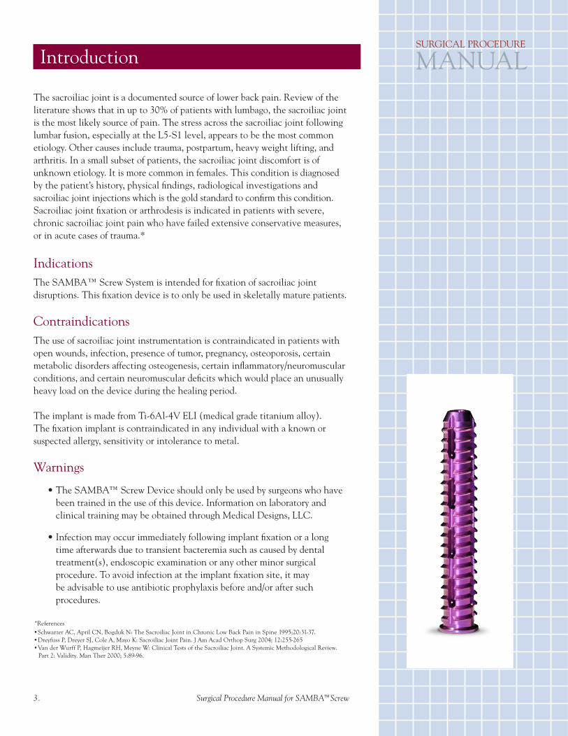
SAMBA™ SCREW(9mm x 50mm L)
Introduction
Indications
Contraindications
Warnings
Potential Adverse Events
Implant Device Overview
Instrument Overview
Surgical Technique
Step One: Preoperative Patient SetupStep Two: Incision LocationStep Three: Placement of Steinmann PinStep Four: Drill Guide Assembly and Drill Guide InsertionStep Five: Selection of SAMBATM Screw LengthStep Six: Drilling of Pilot HoleStep Seven: Placement of SAMBATM Screw and FixationStep Eight: Additional Packing of SAMBATM Screw and/or Sacroiliac Joint with Demineralized Allograft Bone (step is optional)Step Nine: Placement of Multiple SAMBATM ScrewsStep Ten: Wound Closure Postoperative CareDevice Retrieval Efforts
The sacroiliac joint is a documented source of lower back pain. Review of the literature shows that in up to 30% of patients with lumbago, the sacroiliac joint is the most likely source of pain. The stress across the sacroiliac joint following lumbar fusion, especially at the L5-S1 level, appears to be the most common etiology. Other causes include trauma, postpartum, heavy weight lifting, and arthritis. In a small subset of patients, the sacroiliac joint discomfort is of unknown etiology. It is more common in females. This condition is diagnosed by the patient’s history, physical findings, radiological investigations and sacroiliac joint injections which is the gold standard to confirm this condition. Sacroiliac joint fixation or arthrodesis is indicated in patients with severe, chronic sacroiliac joint pain who have failed extensive conservative measures, or in acute cases of trauma.*
IndicationsThe SAMBA™ Screw System is intended for fixation of sacroiliac joint disruptions. This fixation device is to only be used in skeletally mature patients.
ContraindicationsThe use of sacroiliac joint instrumentation is contraindicated in patients with open wounds, infection, presence of tumor, pregnancy, osteoporosis, certain metabolic disorders affecting osteogenesis, certain inflammatory/neuromuscular conditions, and certain neuromuscular deficits which would place an unusually heavy load on the device during the healing period.
The implant is made from Ti-6Al-4V ELI (medical grade titanium alloy). The fixation implant is contraindicated in any individual with a known or suspected allergy, sensitivity or intolerance to metal.
Warnings
• The SAMBA™ Screw Device should only be used by surgeons who have been trained in the use of this device. Information on laboratory and clinical training may be obtained through Medical Designs, LLC.
• Infection may occur immediately following implant fixation or a long time afterwards due to transient bacteremia such as caused by dental treatment(s), endoscopic examination or any other minor surgical procedure. To avoid infection at the implant fixation site, it may be advisable to use antibiotic prophylaxis before and/or after such procedures.
2. Surgical Procedure Manual for SAMBATM Screw 3. Surgical Procedure Manual for SAMBATM Screw
Introduction
*References•Schwarzer AC, April CN, Bogduk N: The Sacroiliac Joint in Chronic Low Back Pain in Spine 1995;20:31-37.•Dreyfuss P, Dreyer SJ, Cole A, Mayo K: Sacroiliac Joint Pain. J Am Acad Orthop Surg 2004; 12:255-265•Van der Wurff P, Hagmeijer RH, Meyne W: Clinical Tests of the Sacroiliac Joint. A Systemic Methodological Review. Part 2: Validity. Man Ther 2000; 5:89-96.
SURGICAL PROCEDURE
MANUAL

SCREW SYSTEM SAMBA
TM
Potential Adverse EventsPotential adverse events that may occur with the SAMBA™ Screw, and complications related to sacroiliac joint instrumentation which may require medical management or surgical intervention include:
• Allergic reaction or metal sensitivity to foreign body;• Cardiovascular system compromise;• Death;• Decrease in bone density due to stress shielding;• Device bending, disassembly, fracture, loosening, migration and/or retropulsion, or subsidence; • Dural tears, neural structure injury;• Fixation implant migration with or without bone fracture;• Fracture of pelvis or sacrum;• Gastrointestinal complications (i.e. ileus or bowel perforation);• Hemorrhage;• Incisional complications (i.e. dehiscence, hematoma);• Infection (Incisional or implant site);• Loss of spinal mobility or function;• Loosening or fracture of fixation implant;• Malfunction of fixation device and/or instruments;• Malposition of the fixation device;• Migration of fixation implant;• Neurological injury/deficit which may range from paresthesias to muscle paralysis, loss of rectal or bladder sphincter control, radiculopathies;• Organ, connective tissue or nerve damage;• Osteoarthritis;• Pain, discomfort or abnormal sensation due to device presence;• Persistent low back pain;• Reproductive system compromise;• Screw back-out or breakage possibly leading to local pain, perforation or irritation of adjacent structures;• Sepsis;• Urological compromise (i.e. infection/retention);• Vascular injury;• Wound Hematoma
Patient’s willingness to follow instructions is most important for successful bone healing. The patient must be made aware of the limitations of the fixation device implant, and needs to be instructed to limit and/or restrict physical activities such as, but not limited to, non-weight bearing or partial weight bearing, lifting, twisting and participation in sports. The patient should be made aware that a metallic implant is not as strong as normal healthy bone, and there is a possibility that the fixation implant may bend and/or break if excessive demands are placed on it, especially in the absence of complete bone healing. Fixation implant(s) displaced or damaged by improper activities may migrate or damage the surrounding soft tissues. A debilitated or demented patient who cannot properly use weight supporting devices may be particularly at risk especially during the postoperative rehabilitation period.
4. Surgical Procedure Manual for SAMBATM Screw
EVENTS

Any of the following fixation device complications may occur: corrosion with localized tissue reaction or pain; migration of implant position resulting in injury; risk of loosening and/or breakage which could make removal impractical or difficult; pain, discomfort or abnormal sensation due to the device; bone loss due to stress shielding; possible increased risk of infection. The surgeon should carefully weigh the risk versus benefit when deciding whether or not to remove the fixation implant. If the fixation implant is in good position, removal should not be performed. If the fixation device is malpositioned and the surgeon feels that removal is indicated, the removal process for the fixating implant should be followed by adequate postoperative management to avoid re-fracture or deformity. If the patient is older and has a low activity level, the surgeon may choose not to remove the fixation implant, thus eliminating the risk associated with any second surgery.
Implant Device OverviewThe SAMBA™ Screw System is manufactured in the United States of America from medical grade titanium (Ti-6Al-4V ELI). It consists of a 9 mm diameter, cannulated screw with multiple orifices on its shaft. The SAMBA™ Screw is pre-packaged as single units. It is a sterile, single use device; it is pre-sterilized by exposure to gamma radiation.Various length sizes available are:
• SAMBA™ Screw, 25mm (11-1109-FD1)• SAMBA™ Screw, 30mm (11-1109-FD2)• SAMBA™ Screw, 35mm (11-1109-FD3)• SAMBA™ Screw, 40mm (11-1109-FD4)• SAMBA™ Screw, 45mm (11-1109-FD5)• SAMBA™ Screw, 50mm (11-1109-FD6)
Instrument OverviewUse of the specialized instruments designed and provided by Medical Designs, LLC, assure accurate implantation of the fixation device.
Each of the components should be intact upon receipt. If a loaner or consignment system is used, all sets should be carefully checked for completeness and all components including instrumentation should be carefully checked to ensure that there is no damage prior to use. Damaged packages or products should not be used, and should be returned to Medical Designs, LLC.
Instruments for implantation of the SAMBA™ Screw include:• Parallel Guide Set (11-1109-FD7)• Packing Plunger (11-1109-FD8-1)• Packing Tube (11-1109-FD8-2)• Variable Drill Bit (11-1109-FD9-1)• Adjustable Drill Collar (11-1109-FD9-2)• Drill Guide (11-1109-FD10)• Pin Sleeve (11-1109-FD11)• Drill Gauge (11-1109-FD12)• Striker Tube (11-1109-FD13)• Cannulated Torx® Driver Bit (11-1109-FD14)• Plunger Distance Tool (11-1109-FD15)• Sharp Steinmann Pin, 9” Ø 3.20mm (11-1109-FD16) • Short Blunt Steinmann Pin, 229mm, Ø 3.20mm (11-1109-FD20) • Long Blunt Steinmann Pin, 457mm, Ø 3.20mm (11-1109-FD21)• Torx® Bit T-Handle (11-1109-FD17)• Drill Bit T-Handle with Key (11-1109-FD18)
4. Surgical Procedure Manual for SAMBATM Screw 5. Surgical Procedure Manual for SAMBATM Screw
OVERVIEWSURGICAL PROCEDURE
MANUAL

SCREW SYSTEM SAMBA
TM
(Fig.1)
(Fig. 2)
(Fig. 3)
(Fig. 4)
6. Surgical Procedure Manual for SAMBATM Screw
PROCEDURE
The SAMBA™ Screw Instruments used to implant the SAMBA™ Screw are provided non-sterile, and must be cleaned and sterilized in the Medical Designs’ Sterilization Tray prior to each use, as described in the SAMBA™ Screw System Instructions for Use.
Note: All instruments, with the exception of the Steinmann Pins (11-1109-16, 11-1109-20, and 11-1109-21), Variable Drill Bit (11-1109-9-1), and Packing Tube (11-1109-8-2) are reusable. The Steinmann Pins, Drill Bit, and Packing Tube are single use devices and should be discarded after use.
Surgical TechniqueStep One: Preoperative Patient Setup The patient should be positioned prone on the operative table. Two C-arm fluoroscopy units are used to provide simultaneous lateral and Ferguson’s views.EMG and somatosensory evoked potentials are utilized during the procedure for increased safety. Using EMG, the following muscles are monitored during surgery:
• L5 root, the anterior tibialis • S1 root, the gastrocnemius • S2 root, rectal sphincter
Step Two: Incision LocationUtilizing the lateral fluoroscopy, the skin is marked. Use a long, blunt Steinmann Pin to locate and mark the skin along the S1 endplate and sacrum posterior cortical wall. The incision location should start approximately 1 cm below and approximately 1 cm posterior to these two lines respectively and extended caudal parallel to the sacrum posterior cortical wall skin mark, and should measure approximately 2-3 cm. In an obese patient the incision should be slightly more posterior. The soft tissue should be dissected down all the way to the ilium.
Step Three: Placement of Steinmann Pin
The sharp, 9 inch Steinmann Pin should be advanced all the way through the incision to the ilium. Utilizing biplane fluoroscopy, the position of the entry point should be checked, as well as the direction of the pin. The entry point should be on a plane at the level of the posterior one-third of the sacrum vertebral body or just anterior to the sacral spinal canal, which is checked on the lateral fluoroscopy view. On the Ferguson view, the pin should point just above the S1 nerve root foramen. For safety reasons the pin should not be directed towards the S1 nerve root foramen, for if the pin is advanced too far it may injure this nerve root. Constant monitoring of somatosensory evoked potentials and EMG is of utmost importance. If the pin is positioned too superior it may injure the L5 nerve root as well as enter the sacral ala and this is not desired for fixation of the sacroiliac joint. On the lateral plane the pin should be directed anteriorly. This is accomplished by elevation of the hand by 10-15 degrees. Under biplane fluoroscopic control, the pin should be advanced using a mallet across the sacroiliac joint and the final position of the tip of the pin should be at approximately 1 cm from the anterior sacral wall, thus avoiding accidental entrance into the pelvis and just lateral to the level of the neuroforamen. (Fig. 1)

Step Four: Drill Guide Assembly and Drill Guide Insertion
Assemble the Pin Sleeve and Drill guide together by inserting the Pin Sleeve through the top of the Drill Guide and threading until the Pin Sleeve stops rotating. (Fig. 2) Once assembled, the Pin Sleeves’ tapered trocar tip will protrude beyond the tip of the Drill Guide; the Drill Guide has five (5) spikes that will anchor the Drill Guide to the ilium. Insert the assembled Drill Guide over the Steinmann Pin until the Pin Sleeve tip is firmly against the ilium. In order to engage the ilium with the Drill Guide terminal spikes, unscrew the Pin Sleeve from the Drill Guide while simultaneously advancing the Drill Guide. Continue this maneuver until the Pin Sleeve threads are fully disengaged from the Drill Guide head and the Drill Guide spikes are against the ilium. Now install the Striker Tube onto the Drill Guide so that the notch at the base of the Striker Tube aligns with the Drill Guide handle. (Fig. 3) Using a mallet, tap the Striker Tube until the Drill Guide is secured and no movement identified. (Fig. 4) Once the Drill Guide is secured to the ilium, remove the Striker Tube and Pin Sleeve from the Drill Guide. (Fig. 5)
Step Five: Selection of SAMBA™ Screw Length
Slide the Drill Gauge over the Steinmann Pin until it makes contact and rests flat on the Drill Guide. (Fig. 6) Read the Drill Gauge according to where the top of the Steinmann Pin falls; this number represents the length of SAMBA™ Screw to select. Remove Drill Gauge.
Step Six: Drilling of Pilot HoleOnce the appropriate SAMBA™ Screw length has been selected, place the Adjustable Drill Collar (security stop) over the Variable Drill Bit to prevent over-penetration. (Fig. 7) Ensure that the Adjustable Drill Collar is set to the proper position and secure prior to insertion of the Variable Drill Bit into the Drill Guide. The Adjustable Drill Collar position should match the Drill Gauge value and selected SAMBA™ Screw. Connect the Variable Drill Bit to the Drill Bit T-handle and hand tighten the chuck and/or use the key provided for additional tightening. Alternatively, the Variable Drill Bit may be connected to an electrical drill. Under fluoroscopy, preferably the Ferguson view, a pilot hole is then created just short of the tip of the Steinmann Pin. (Fig. 8) The Adjustable Drill Collar will control the depth of the pilot hole. Once the desired depth is reached the Variable Drill Bit is then removed along with the Steinmann Pin.
Note: If the Variable Drill Bit, instead of sliding over the Steinmann Pin, appears to be advancing the Steinmann Pin, the Steinmann Pin should be removed and replaced by a blunt Steinmann Pin or the pilot hole drilled without Steinmann Pin guidance.
(Fig. 5)
(Fig 6)
(Fig. 7)
(Fig. 8)
7. Surgical Procedure Manual for SAMBATM Screw
PROCEDURESURGICAL PROCEDURE
MANUAL

SCREW SYSTEM SAMBA
TM
Step Seven: Placement of SAMBA™ Screw and Fixation
The SAMBA™ Screw is filled with Demineralized Allograft (or Autograft) Bone prior to insertion. Slide the SAMBA™ Screw into the Drill Guide until it rests on the ilium. (Fig. 9) Install the Cannulated Torx® Driver Bit into the Torx® Bit T-Handle until an audible click is detected. Insert the assembled Cannulated Torx® Driver Bit, and under fluoroscopy guidance, advance the selected SAMBA™ Screw into the pilot hole until the screw head stops against the ilium. (Fig. 10) The laser marking on the Cannulated Torx® Driver Bit will indicate when to stop advancing the screw in addition to the resistance that is felt when the screw head stops against the ilium. Remove the Cannulated Torx® Driver Bit once this procedure is complete.
If the Drill Guide spike(s) detach from the ilium or fail to stabilize the Drill Guide, a blunt Steinmann Pin should be inserted into the pilot hole and the SAMBA™ Screw should slide down the Steinmann Pin.
Step Eight: Additional Packing of SAMBA™ Screw and/or Sacroiliac Joint with Demineralized Allograft Bone (step is optional)
Remove the Steinmann Pin (if present). With the Drill Guide still in place, at the surgeon’s discretion, the implant and/or Sacroiliac Joint may be packed with demineralized allograft bone using the Packing Plunger Assembly. (Fig. 11) (It should be noted that the Plunger Distance Tool will aid in presetting the Packing Plunger Assembly to the correct depth in preparation of bone packing.) Once the amount of demineralized allograft bone to be injected has been determined, usually 2 cc to 4 cc, the Packing Plunger Assembly is loaded and engaged to the SAMBA™ Screw. The demineralized allograft bone is then injected applying sufficient pressure. This demineralized allograft bone, which is usually a soft paste, penetrates the screw, ilium, the sacrum and the sacroiliac joint. This bone packing step is optional and may, in the long-run, strengthen the construct by promotion of bone growth into the screw and sacroiliac joint. The surgeon may use autograft bone instead of demineralized allograft material.
Step Nine: Placement of Multiple SAMBA™ Screws
For adequate fixation, it is recommended that three (3) SAMBA™ Screws be implanted, but occasionally, due to anatomic variations of the sacroiliac joint, two (2) or four (4) implants may be used.
With the Drill Guide in place, install the Parallel Guide Assembly into the Drill Guide. (Fig. 12) The Parallel Guide Assembly distance between successive SAMBA™ Screws should be set prior to insertion into the Drill Guide. The fixed pin guide of this instrument slips into the Drill Guide, or over the Steinmann Pin if present. The second pin guide of the Parallel Guide Instrument, which is attached to the Sliding Block, will guide the direction of the second Steinmann Pin. The second SAMBA™ Screw entry point should be on a plane just anterior to the spinal canal at a level just below the S1 neuroforamen. Once a final position of the second pin guide has been determined using fluoroscopy, a second Steinmann Pin is placed into the second pin guide tube. Using a mallet, the Steinmann Pin is advanced across the sacroiliac joint,
(Fig. 9)
(Fig.10)
(Fig.11)
8. Surgical Procedure Manual for SAMBATM Screw
PROCEDURE

again under biplane fluoroscopy guidance. (Fig. 13) The Steinmann Pin is usually stopped lateral to the level of the S1 and S2 neuroforamen.
Once the second Steinmann Pin is in the desired position and parallel to the first implant, the Parallel Guide Instrument, Drill Guide and first Steinmann Pin (if present) are removed and the entire procedure is repeated for insertion of the second implant. (Fig. 14)
A third or fourth implant may be inserted using the same technique. The third implant should be located just above the S2 foramen level. If in view of anatomic constraints the third or any screw has to be at the level of a neuroforamen, care is taken not to advance the Steinmann Pin or the Adjustable Drill Bit too far into these structures. If correct measurement of the implant is performed, the SAMBA™ Screw’s head should stop at the ilium and not compromise any deeper structure.
Prior to wound closure, all implants should be visualized by fluoroscopy not only in the lateral and Ferguson’s views, but also in the oblique, AP and inlet views to ascertain proper position of the implants, which should be across the sacroiliac joint without violating the spinal canal, the neuroforamen(s), the anterior sacral cortical wall and the sacral ala.
Step Ten: Wound Closure
Following meticulous hemostasis, the wound should be closed using standard surgical technique.
Postoperative Care
The patient may be discharged within 24 hours following surgery. The patient may ambulate, however, it is recommended for two weeks following surgery to use a walker or crutches to decrease weight bearing by at least 50% on the operated side.
Device Retrieval Efforts
If the fixation device is malpositioned and the surgeon feels that removal is indicated, the removal process for the fixating implant should be followed by adequate postoperative management to avoid re-fracture or deformity. If the patient is older and has a low activity level, the surgeon may choose not to remove the fixation implant, thus eliminating the risk associated with any second surgery.
Should it be necessary to remove a SAMBA™ Screw, the patient is positioned in a similar fashion as for screw insertion. Biplane fluoroscopy is brought into the operative field. The wound is reopened utilizing standard surgical technique. Using the Cannulated Torx® Driver Bit under fluoroscopic guidance, the head of the screw to be removed is engaged and rotated counter-clockwise until the screw is out.
If the surgeon desires to replace the screw, prior to its removal, a short blunt Steinmann Pin should be inserted through the Cannulated Torx® Driver Bit. The screw is then removed as described above, and the Steinmann Pin is used as a guide for the new screw. Wound closure and postoperative care, as per protocol.
Warning: If the screw has been in place for a sufficient amount of time for bone to
(Fig.12)
(Fig.13)
(Fig.14)
9. Surgical Procedure Manual for SAMBATM Screw
PROCEDURESURGICAL PROCEDURE
MANUAL

SCREW SYSTEM SAMBA
TM
IMPLANTS
Description Model Number
9mm x 25mm L 11-1109-FD1 9mm x 30mm L 11-1109-FD2 9mm x 35mm L 11-1109-FD3 9mm x 40mm L 11-1109-FD4 9mm x 45mm L 11-1109-FD5 9mm x 50mm L 11-1109-FD6
INSTRUMENTS
Description Model Number
Parallel Guide Set 11-1109-FD7 • Includes Parallel Guide Frame • Parallel Guide Locking Nut • Parallel Sliding Block Packing Plunger 11-1109-FD8-1 Adjustable Drill Collar 11-1109-FD9-2 Drill Guide 11-1109-FD10 Pin Sleeve 11-1109-FD11 Drill Guage 11-1109-FD12 Striker Tube 11-1109-FD13 Cannulated Torx® Driver Bit 11-1109-FD14 Plunger Distance Tool 11-1109-FD15 Torx® Bit T-Handle 11-1109-FD17 Drill Bit T-Handle with Key 11-1109-FD18
DISPOSABLE INSTRUMENTS Description Model Number
Packing Tube 11-1109-FD8-2 Variable Drill Bit 11-1109-FD9-1 Sharp Steinmann Pin, 9” 11-1109-FD16 Short Blunt Steinman Pin 229mm 11-1109-FD20 Long Blunt Steinman Pin 457mm 11-1109-FD21
Drill Gauge11-1109-12
Striker Tube11-1109-13
Cannulated Torx® Driver Bit11-1109-14
Sharp Steinmann Pin 9”11-1109-16
Packing Tube11-1109-8-2(with top view)
Short Blunt Steinmann Pin, 229mm11-1109-20
Long Blunt Steinmann Pin,457mm11-1109-21
Packing Plunger11-1109-8-1(with top view)
10. Surgical Procedure Manual for SAMBATM Screw
SAMBATM SCREW SYSTEM (Implants and Instruments)

AdjustableDrill Collar11-1109-9-2
9mm
x 2
5mm
L
11-1
109-
FD1
9mm
x 3
0mm
L
11-1
109-
FD2
9mm
x 3
5mm
L
11-1
109-
FD3
9mm
x 4
0mm
L
11-1
109-
FD4
9mm
x 4
5mm
L
11-1
109-
FD5
9mm
x 5
0mm
L
11-1
109-
FD6
Parallel Guide11-1109-7(Frame, Sliding Block & Locking Nut)
Drill Bit T-Handlewith Key11-1109-18
Torx® Bit T-Handle11-1109-17
Plunger Distance Tool11-1109-15(front)
Variable Drill Bit11-1109-9-1
Packing Plunger11-1109-8-1(with top view)
11. Surgical Procedure Manual for SAMBATM Screw
SAMBATM SCREW SYSTEM (Implants and Instruments)
Drill Guide11-1109-10
Pin Sleeve11-1109-11
SAMBATM SCREWIMPLANTS

6709 South Minnesota Avenue, Suite 204, Sioux Falls, SD 57108 Phone: (888) 276-7271 Fax: (605) 335-3734
www.medicaldesignsllc.com
©2014 Medical Designs, LLC All Rights Reserved. Patents Pending ED0230RB
SAMBATM SCREW SYSTEM STERILIZATION CASE Model Number: 11-1109-19 (pictured with instruments)