sae mil-1394 for military and aerospace vehicle applications · pdf filesae mil-1394 for...
TRANSCRIPT

SAE Mil-1394 For Military and Aerospace Vehicle
Applications
Mike Wroble and Jack Kreska, Lockheed Martin Aeronautics Company
Larry Dungan, National Aeronautics and Space Administration
https://ntrs.nasa.gov/search.jsp?R=20060009084 2018-05-19T00:29:51+00:00Z

Agenda
hThe SAE Mil-1394 StandardhMil-1394 On The F-35 Joint Strike FighterhMil-1394 On The Space Shuttle
Paper #

IEEE-1394 Historyh IEEE-1394 began as a development by Apple Computer in
the 1980s. The project was named FireWire.h In 1995, the IEEE released a standard based on Apple’s
FireWire: IEEE Std 1394-1995.h In 1997 the OHCI (PCI bus interface) was defined.h In 1998 the 1st amendment for 1394a was made
available.h In 1999 the 1st draft of the 1394b standard was made
available.h In 2000 the IEEE Std 1394a-2000 was released.h In 2002 the IEEE Std 1394b-2002 was released.
Paper #

The SAE AS-1A3 Mil-1394 Task GroupThe SAE AS-1A3 Task Group was formed to establish requirements for using 1394 in safety-critical/ mission-critical applications for military and aerospace vehicles.hQuarterly meetings have been held since July, 2003.hTask Group consists of 19 active members and 27
distribution members, representing aerospace and military corporations, test equipment vendors, and chip suppliers.
hBase Specification and accompanying Slash Sheet (S400 Copper) balloted in August, 2004.
hFuture work includes drafting a Handbook and Slash Sheets for other media and bus speeds.
Paper #

Additions To IEEE-1394 Standards hUse of Asynchronous StreamshAsynchronous streams are used for most
communication on the network. Asynchronous and isochronous packets are not required but may be utilized.
hA Fixed Frame RatehThis implementation provides a fixed frame rate for
synchronization of the network.
hSynchronization Via Start Of Frame PacketshA Start Of Frame (STOF) packet is transmitted by the
Control Computer on each bus at a periodic (e.g. 100 Hertz) frame rate. This packet informs all nodes on the bus that a new frame has started.
Paper #

Additions To IEEE-1394 (Cont.) hStatic Assignment of Channel NumbershThe channel numbers for each node on the bus are
pre-assigned, are application specific, and will be defined as required by the architecture.
hPre-Assignment of BandwidthhTransmit and receive times for each node on the bus
are assigned as offsets from the start of each frame (STOF packet).
hVertical Parity CheckhVertical Parity Checking (VPC) is performed on the data
area of each packet as an adjunct to the Cyclic Redundancy Check (CRC) performed by the 1394 physical layer devices.
Paper #

Additions To IEEE-1394 (Cont.) hAnonymous Subscriber MessaginghAnonymous Subscriber Messaging (ASM) is a protocol in
which a Remote Node on the network can subscribe to each message that it requires. The ASM software in the Remote Node will forward only the messages to which the Remote Node has subscribed.
Paper #

Hardware Slash Sheets hHardware Slash Sheets are used to establish hardware
guidelines for different system applications and bus speeds.hWhile environmental requirements (electromagnetic
compatibility, temperature, vibration, etc.) are vehicle- and even LRU-specific, the hardware requirements and examples in a Slash Sheet address many of the environmental conditions that military and aerospace vehicles may experience.
hThe S400 Copper Slash Sheet is the first one created by the SAE AS-1A3 Task Group. Future Slash Sheets may be used for different bus speeds (S200, S800, etc.), bus media (copper, glass or plastic optical fiber, etc.), and applications.
Paper #

S-400 Slash Sheet The S400 Copper Slash Sheet establishes guidelines for the data bus cable and its interface electronics for a system utilizing S400 over copper medium over extended lengths.• Cable Electrical Characteristics• Cable Termination
• Connectors/Contacts• Termination Method
• Bus Isolation (Transformers)• Link Signal Specifications
• Link Signal Transmitter Characteristics (TP2)• Link Signal Receiver Characteristics (TP3)
Paper #

Mil-1394 On The F-35 Joint Strike Fighter (JSF) Aircraft
Paper #

Aircraft Avionics Data Bus BackgroundLegacy Aircraft Programs Employed “Federated” Subsystems:
• Architecture Made Use Of Federated Controllers For Specific Applications Requiring Dedicated, High-bandwidth Control Loops
• Data Shared Between Distributed Processing Required Minimal Bandwidth
• High Bandwidth Sensor Data Provided as Analog Inputs (e.g Air Data)
Mil-Std-1553B Protocol Fulfilled Needs:• Digital Data Transferred Between Multiple Avionics
Units Over Common Data Bus Media Using Time Division Multiplexing (TDM)
• Half-duplex, Asynchronous, Command/Response Protocol, Dual Redundancy
• 1 Megabits Per Second (Mbps)• Mil-Std-1553 Released In 1973, Mil-Std-1553a In
1975, Mil-Std-1553b In 1978
FederatedSubsystemsFederatedSubsystems
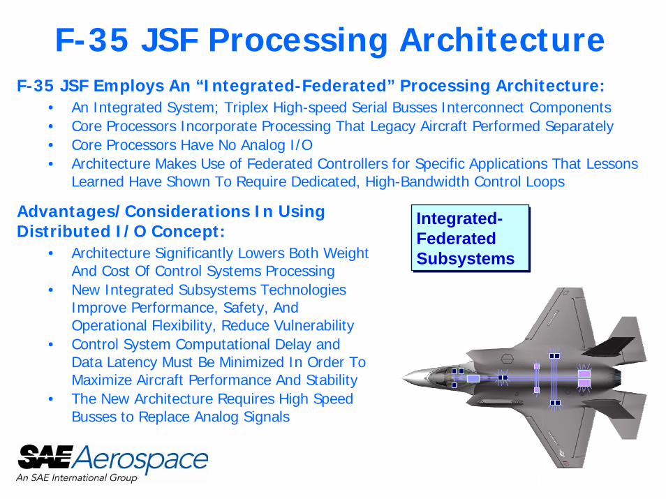
F-35 JSF Processing ArchitectureF-35 JSF Employs An “Integrated-Federated” Processing Architecture:
• An Integrated System; Triplex High-speed Serial Busses Interconnect Components• Core Processors Incorporate Processing That Legacy Aircraft Performed Separately• Core Processors Have No Analog I/O• Architecture Makes Use of Federated Controllers for Specific Applications That Lessons
Learned Have Shown To Require Dedicated, High-Bandwidth Control Loops
Advantages/Considerations In Using Distributed I/O Concept:
• Architecture Significantly Lowers Both Weight And Cost Of Control Systems Processing
• New Integrated Subsystems Technologies Improve Performance, Safety, And Operational Flexibility, Reduce Vulnerability
• Control System Computational Delay and Data Latency Must Be Minimized In Order To Maximize Aircraft Performance And Stability
• The New Architecture Requires High Speed Busses to Replace Analog Signals
Integrated-FederatedSubsystems
Integrated-FederatedSubsystems

Why Was 1394b Selected For The F-35 JSF Vehicle Systems Data Bus?
To Support New Architectural Advantages, Vehicle Systems (VS) Needed A High-Throughput Data Bus That Could Fulfill The Following Requirements:
• No Loss Of Data Due To Bus Overflow/Collision• Guaranteed Data Delivery/Detection Of Failed Delivery• Availability Of Parity/Error Detection Codes• Rapid Network Initialization• Fault Tolerant Topology With No Single Point Failure Causing Loss Of An Entire Bus
A Supplier Trade Study Determined That The Most Cost-Effective VS Aircraft Network Protocol Is IEEE-1394b:
• IEEE-1394b Provides An Extremely High Bandwidth Bus - 400 Megabits Per Second (Mbps) Selected For VS Data Bus And Core Processor Cross Channel Data Link
• Topology And Features Of 1394b Fit Well With VS Connectivity, Fault Tolerance, And Environmental Requirements
• IEEE-1394b Is A Fully Arbitrated, Peer-To-Peer Serial Bus Communication Protocol• IEEE-1394b Offers 8b/10b Encoding That Is Suitable For The EMI/EMC Environment
Seen In The Application• IEEE-1394b Physical Layer Is Compatible With The IEEE-1394a Link Layer
• Use Of The 1394a Link Layer Enabled Software Development To Proceed Using Available 1394a Devices

Vehicle Systems Data Bus Trade StudyN
etw
ork
Wei
ght
Pow
er
Vol
ume
Late
ncy
Topo
logy
Rob
ustn
ess
S/W
Dev
elop
men
t Im
pact
H/W
Dev
el R
isk
EEE
Rob
ustn
ess
Tech
Ref
resh
Pat
hN
on R
ecur
ring
Cos
t Im
pact
sR
ecur
ring
Cos
t Im
pact
sC
usto
mer
Acc
epta
nce
Com
men
ts
Sco
re
Ran
king
IEEE 1394b, 100Mbps Passive
Not Viable - S100 Parts Not Initially Available n/a
IEEE 1394a Not Viable - Failed Lightning Testing n/aIEEE 1394b, 400Mbps Passive
Passed EEE and Lighting. Selected For Root Proc Cross-Channel Data Link 1
IEEE 1394b, 400Mbps Active
Uses Active Xfmrs To Achieve 10+ Meters And Pass EEE And Lightning. Selected For VS Network. 2
IEEE 1394b, Optical
Needs Optical Xcvrs. Selected For Remote Flight Testing. 4
ATM, Optical Switched Topology, No Flight H/W 8Fibre Channel, Electrical
Loop Topology, Rehost ASM; power and s/w dev schedule concerns. 5
Fibre Channel, Optical
Loop Topology, Rehost ASM; power and s/w dev schedule concerns. 6
EtherNetHub Topology, No Determinism, EEE concerns, Possible Fallback? 3
USB Switched Topology, No Flight H/W 7
Mil-Std-1553Limited Bandwidth, Architecture Impacts, Latency & Weight Cons 9
Note: Study Focused on Lower Bandwidth Vehicle Systems – Not Applicable to Mission Systems Applications

Vehicle Systems Data Bus OverviewVehicle Systems Data Bus Protocol
• Asynchronous Streams Used As Main Method Of Data Transport• Asynchronous Streams Are Isochronous Data Packets (Same Addressing
Scheme, Packet Size, Etc) That Are Transmitted Under Asynchronous Transaction Rules (Asynchronous Size Limitations, After Isochronous Packets, No Ack)
• Addressed Via Channel Number, So No Node Discovery Is Necessary (As Would Be The Case For Asynchronous Transactions); Easily Filtered By LLC.
• Asynchronous Transactions Required “Extra” Overhead That Was Not Necessary To Carry Around
• No Guaranteed Delivery So Extra Failure Management Requirements Must Be Levied
• Asynchronous transactions are addressed to specific memory locations thus permitting memory corruption by incorrectly addressed packets• Asynchronous streams, however, are addressed to channel numbers• If a packet is sent to an incorrect channel number, the receiving node will
ignore it – no chance of damage

Bandwidth and Latency Management Channel Numbers are pre-assigned in the VSN ICD
• Improves VSN Start Up because discovery is not required
Bandwidth is assigned via the STart Of Frame (STOF) offsets• The VSN implementation does not utilize an Isochronous Resource
Manager
STOF message transmission establishes VS frame• No Cycle Start packet is transmitted every 125 usec. Instead, a STart
Of Frame (STOF) packet is transmitted every 12.5 milliseconds
STOF Offset allocations enable low latency performance• Each node on the bus is assigned a time, relative to the STOF, when
it can expect to have receive data in the LLC’s FIFO, • Another time, relative to the STOF, when it is permitted to transmit
data, and • A third time, also relative to the STOF, when it may transmit its Data
Pump packets

VSN Bus TimingThis figure illustrates the concept of STOF offset timing as utilized on the JSF Vehicle Systems Network
Frame n-1 -
Node A Data Latency
Node A STOF
Transmit Offset
12.5 ms Frame n Frame n+1
Node A TransmitNode A Data
Available VMC Transmit
VMC Transmit
Node A Transmit
STOFn STOFn+1
Node A STOF
Receive Offset

1394b Total Initialization Timing
Tree IDStarts
SelfID
330 - 350 ms 10 - 166 us 70 us
Bus Init Timing
Tree IDTime
Self IDTime
Total ID Time
Total Bus Initialization Timing
NodeConnect
DisconnectPowerOn/Off
ConfigurationComplete
SpeedNegotiation
Starts
127 ms.
Toning
• As each Remote Node is connected or powered on, it internally generates the 350-millisecond debounce delay. Upon completion of the debounce delay, it sends the reset signal onto the bus. Because not all nodes are powered on at the same time, the initialization of the bus will continue until the final node is powered on.
• During the final component of bus initialization, nodes begin sending tones to one another to negotiate maximum usable speed.
• Following bus initialization, nodes begin the tree-identify and self-identify phases to identify the root node and the topology of all attached nodes.

High-Level VS Processing Architecture
Data Busses1, 2, & 3 Similar
To Branch A
Data Busses1, 2, & 3 Similar
To Branch A
Display Mgmt
Computer
Integrated Core
Processor
Branch AActuation Controllers
Branch AAft Flight Control System Sensors
Branch AUtility Sys Controllers
FADEC 1 & 2Branch AForward Flight Control System Elements
Branch AForwardUtility Sys Controllers
To MissionSystems Fibre
Channel Network
Analog & DiscreteInterfaces
Vehicle Management Computer - Branch A
Vehicle Management Computer - Branch B
Vehicle Management Computer - Branch C
Data Bus1 2 3
Data Bus1 2 3
Data Bus1 2 3
IEEE-1394 (CCDL)400 Megabits per second Vehicle Mgmt ComputerCross-Channel Data Link (CCDL)
IEEE-1394 (VSN)400 Megabits per second Vehicle Systems Network Common Serial Bus Interface Unit (CSBIU)
FlightControl
Systems
UtilitiesAnd
Subsystems
PropulsionMissionSystems
VehicleSystems
Processing
Procuring IPT
Legend
Data Bus TypesBranch ARemote Input / Output Units
Branch ARemote Input/Output Units
Other MS Elements

Vehicle Systems Network Architecture
PROC A PROC B PROC C
0 21
Bus1
0 21
Bus2
0 21
Bus3
0 21
Bus1
0 21
Bus2
0 21
Bus3
0 21
Bus1
0 21
Bus2
0 21
Bus3
Vehicle System Processing
Flight Control Systems
Utilities & Subsystems
Propulsion
Mission Systems
Battery Backed Equipment- (Bold and Underlined)
IEEE-1394 400 Mbps Vehicle System Network
IEEE-1394 400 Mbps Cross-Channel Data Link
Flight Test Instrumentation
20 1
Test 1
20 1
Test 2
20 1
Test 1
20 1
Test 2
20 1
Test 1
20 1
Test 2

Mil-1394 On The Space Shuttle

Space Shuttle Return To Flight• NASA is installing a digital camera in the aft
compartment of the Space Shuttle to take pictures of the external tank separation. The pictures will be downlinked to the ground for analysis while the shuttle is still in orbit.
• The camera is in the umbilical well and the laptop is in the crew cabin. This requires a 125 foot cable run with 10 interconnects.
• COTS Camera and laptop both run 1394a that is converted to 1394b S100 for the cable run.

Background• External Tank Thermal Protection System (ETTPS)
Film Cameras have flown since STS-1• Film is processed post flight• Upgraded to digital camera to allow ETTPS images to
be downlinked and debris imagery analysis on the external tank to be completed within hours of launch.
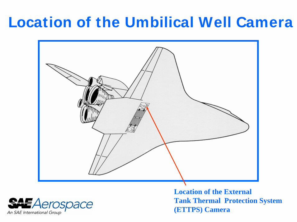
Location of the Umbilical Well Camera
Location of the ExternalTank Thermal Protection System(ETTPS) Camera


Architecture
DETTPS CAMERAIEEE1394a to 1EEE1394b Conversion
LaptopComputer
1
1
2
IEEE1394bto IEEE1394a Conversion
2
IEE
E13
94a
2IEEE1394b
28V PWR

IEEE1394 Overview• COTS Laptop and Camera have IEEE1394a only• Utilizes in-house designed 1394a to 1394b converters• S100 selected because testing showed it would drive 190’
with 15 interconnects. • S200 would drive 125’ of cable but with no signal margin.
• Reasons for converting to 1394b:• Necessary to make the distance of the cable run• AC coupled
• Eliminated DC coupling issues • EMI problems• Lightning hazards• ESD

Overview (Continued)• NASA design only using the Physical Layer (PHY)
• Meets requirements for the Space Shuttle Return to Flight.• PHY mode permanently set to S100.
• PHY could be controlled by a Link Layer Controller (LLC) • PHY and LLC combinations being utilized by LM-Aero. • PHY and LLC combinations planned for future camera
upgrades on Space Shuttle and Space Station.

Radiation Testing• 1394 chipset was tested at the Indiana University
Cyclotron Facility (IUCF) with 200MeV protons• Total Ionizing Dose of 590 Rads(Si) (fluence of
1.0E10 protons/cm**2) was placed on the parts.• No Single Event Effects or Total Dose Effects were
found.• Part MTBF > 10 years of Space Station Low Earth
Orbit assuming 0.1” Aluminum shielding.

Cable Design• Two parallel cables installed in vehicle during
modifications for future utilization.
• High frequency terminations require complete shield termination coverage.• Open or not complete shield braids in existing
technologies including TAG Ring, combed and weaved braids common to RFI backshells and open non-RFI backshells are not compatible for high frequency communication.
Cable Design• Current Space Shuttle wiring is all low frequency
or DC level. • Non-Impedance matched mil standard connectors
utilized. • Connectors were pre-existing in Space Shuttle
from previous applications.• Unique pinouts allow impedance matching and
prevent cross talk issues.

LM-Aero Overview• In researching data transfer methods it was identified that Lockheed
Martin-Aero had been developing IEEE1394b protocols. • LM-Aero was contacted by LM-Space Operations in direct support of
NASA-JSC and a formal work agreement was put in place. • The information transfer allowed board and cable design to quickly be
completed without experiencing a several month learning curve normally associated with high speed digital design projects.
• The parts cost was reduced because LM-Aero has completed parts testing and design certification on the IEEE1394b chipsets being utilized.
• LM-Aero participated at the NASA Project Peer and System Design Reviews.
• LM-Aero has benefited from the lessons learned during the fabrication and testing of hardware.

Summary• Unique opportunity to utilize new technology while increasing
vehicle and crew member safety.• Demonstration of new technology that can be utilized for
Crew Exploration Vehicle and other future manned vehicles. • Future work for other cameras in the vehicle that can be
IEEE1394 based without major vehicle modifications. • Demonstrates that LM can share information and knowledge
between internal groups and NASA to assist in providing a product in support of the NASA Return to Flight Activities.
• This upgrade will provide a flight active data bus that is 100 times faster than any similar bus on the vehicle.