sae mini baja: suspension and steering - welcome · sae mini baja: suspension and steering by zane...
TRANSCRIPT
SAE Mini BAJA: Suspension and Steering
By
Zane Cross, Kyle Egan, Nick Garry, Trevor Hochhaus Team 11
Progress Report
Submitted towards partial fulfillment of the requirements for
Mechanical Engineering Design II – Spring 2015
Department of Mechanical Engineering
Northern Arizona University Flagstaff, AZ 86011
Table of Contents Suspension Recap Steering Recap Changes Possibilities/Looking into changing Future Tasks Conclusion
Suspension Recap
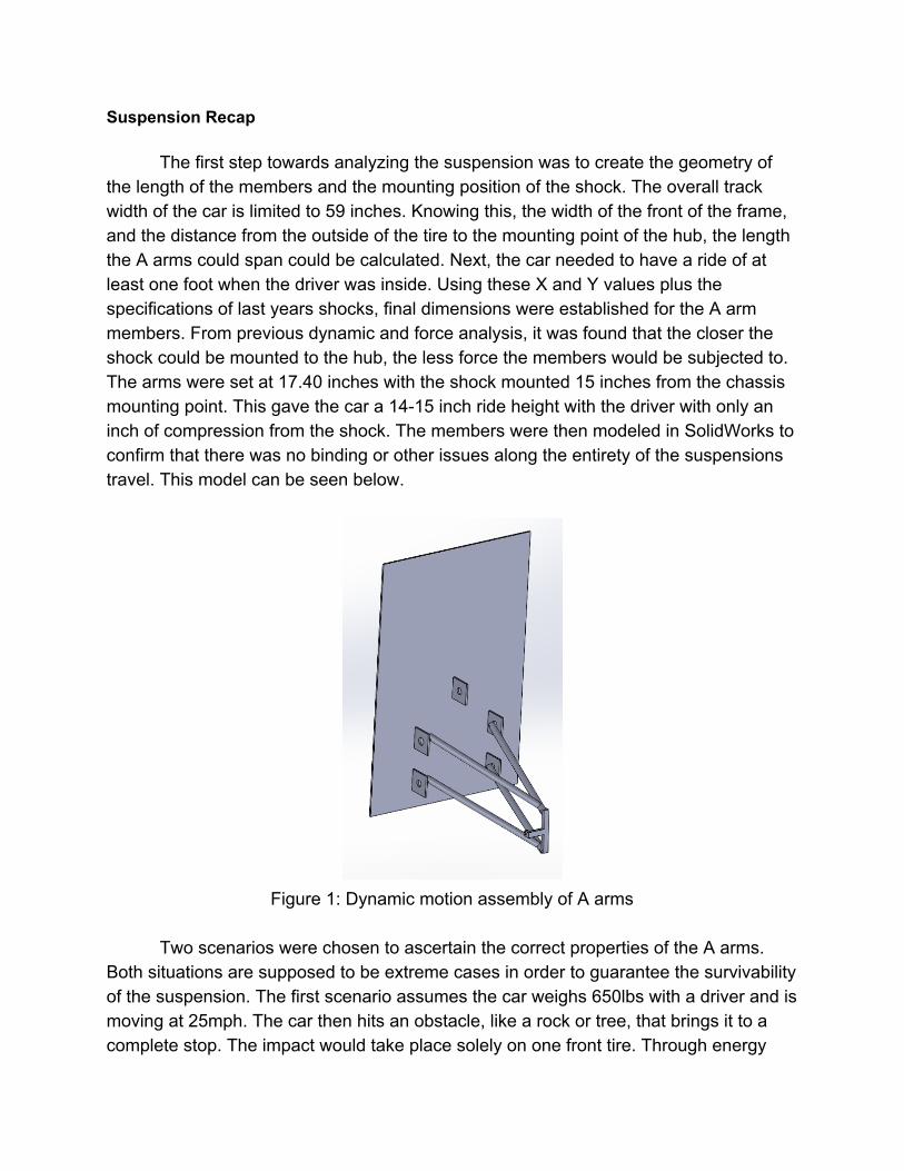
The first step towards analyzing the suspension was to create the geometry of the length of the members and the mounting position of the shock. The overall track width of the car is limited to 59 inches. Knowing this, the width of the front of the frame, and the distance from the outside of the tire to the mounting point of the hub, the length the A arms could span could be calculated. Next, the car needed to have a ride of at least one foot when the driver was inside. Using these X and Y values plus the specifications of last years shocks, final dimensions were established for the A arm members. From previous dynamic and force analysis, it was found that the closer the shock could be mounted to the hub, the less force the members would be subjected to. The arms were set at 17.40 inches with the shock mounted 15 inches from the chassis mounting point. This gave the car a 1415 inch ride height with the driver with only an inch of compression from the shock. The members were then modeled in SolidWorks to confirm that there was no binding or other issues along the entirety of the suspensions travel. This model can be seen below.
Figure 1: Dynamic motion assembly of A arms
Two scenarios were chosen to ascertain the correct properties of the A arms.
Both situations are supposed to be extreme cases in order to guarantee the survivability of the suspension. The first scenario assumes the car weighs 650lbs with a driver and is moving at 25mph. The car then hits an obstacle, like a rock or tree, that brings it to a complete stop. The impact would take place solely on one front tire. Through energy
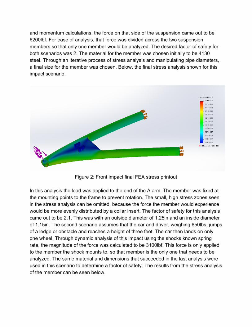
and momentum calculations, the force on that side of the suspension came out to be 6200lbf. For ease of analysis, that force was divided across the two suspension members so that only one member would be analyzed. The desired factor of safety for both scenarios was 2. The material for the member was chosen initially to be 4130 steel. Through an iterative process of stress analysis and manipulating pipe diameters, a final size for the member was chosen. Below, the final stress analysis shown for this impact scenario.
Figure 2: Front impact final FEA stress printout
In this analysis the load was applied to the end of the A arm. The member was fixed at the mounting points to the frame to prevent rotation. The small, high stress zones seen in the stress analysis can be omitted, because the force the member would experience would be more evenly distributed by a collar insert. The factor of safety for this analysis came out to be 2.1. This was with an outside diameter of 1.25in and an inside diameter of 1.15in. The second scenario assumes that the car and driver, weighing 650lbs, jumps of a ledge or obstacle and reaches a height of three feet. The car then lands on only one wheel. Through dynamic analysis of this impact using the shocks known spring rate, the magnitude of the force was calculated to be 3100lbf. This force is only applied to the member the shock mounts to, so that member is the only one that needs to be analyzed. The same material and dimensions that succeeded in the last analysis were used in this scenario to determine a factor of safety. The results from the stress analysis of the member can be seen below.
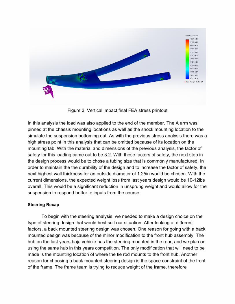
Figure 3: Vertical impact final FEA stress printout
In this analysis the load was also applied to the end of the member. The A arm was pinned at the chassis mounting locations as well as the shock mounting location to the simulate the suspension bottoming out. As with the previous stress analysis there was a high stress point in this analysis that can be omitted because of its location on the mounting tab. With the material and dimensions of the previous analysis, the factor of safety for this loading came out to be 3.2. With these factors of safety, the next step in the design process would be to chose a tubing size that is commonly manufactured. In order to maintain the the durability of the design and to increase the factor of safety, the next highest wall thickness for an outside diameter of 1.25in would be chosen. With the current dimensions, the expected weight loss from last years design would be 1012lbs overall. This would be a significant reduction in unsprung weight and would allow for the suspension to respond better to inputs from the course. Steering Recap
To begin with the steering analysis, we needed to make a design choice on the type of steering design that would best suit our situation. After looking at different factors, a back mounted steering design was chosen. One reason for going with a back mounted design was because of the minor modification to the front hub assembly. The hub on the last years baja vehicle has the steering mounted in the rear, and we plan on using the same hub in this years competition. The only modification that will need to be made is the mounting location of where the tie rod mounts to the front hub. Another reason for choosing a back mounted steering design is the space constraint of the front of the frame. The frame team is trying to reduce weight of the frame, therefore
minimizing the front of the frame. Since the frame will be much smaller at the front, a back mounted steering system was chosen because frame member length would need to increase in order to fit a front mounted steering system. The final reason for choosing a back mounted steering was because mounting the tie rods on the front of the hub assembly would cause space issues. Since the brake caliper mounts on the front of the hub assembly, we would run into issues figuring out a place to mount the tie rod to the hub.
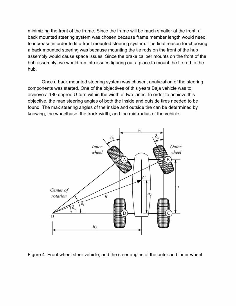
Once a back mounted steering system was chosen, analyzation of the steering components was started. One of the objectives of this years Baja vehicle was to achieve a 180 degree Uturn within the width of two lanes. In order to achieve this objective, the max steering angles of both the inside and outside tires needed to be found. The max steering angles of the inside and outside tire can be determined by knowing, the wheelbase, the track width, and the midradius of the vehicle.
Figure 4: Front wheel steer vehicle, and the steer angles of the outer and inner wheel
With all the variables determined, the max steering angles of the inside and outside tire were calculated.
Inside Tire Max Turning Angle: 35.54 Degrees
Outside Tire Max Turning Angle: 24.90 Degrees
Turning Radius: 9.63 ft
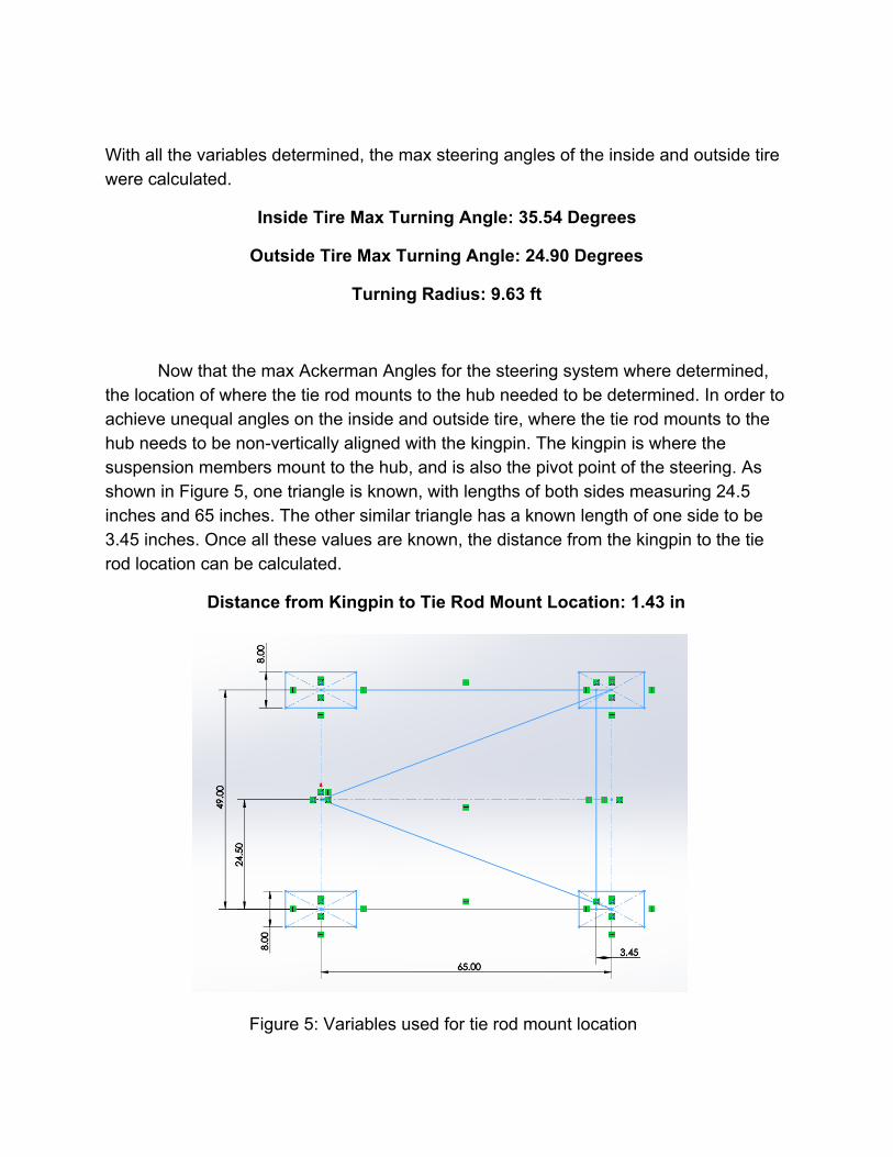
Now that the max Ackerman Angles for the steering system where determined, the location of where the tie rod mounts to the hub needed to be determined. In order to achieve unequal angles on the inside and outside tire, where the tie rod mounts to the hub needs to be nonvertically aligned with the kingpin. The kingpin is where the suspension members mount to the hub, and is also the pivot point of the steering. As shown in Figure 5, one triangle is known, with lengths of both sides measuring 24.5 inches and 65 inches. The other similar triangle has a known length of one side to be 3.45 inches. Once all these values are known, the distance from the kingpin to the tie rod location can be calculated.
Distance from Kingpin to Tie Rod Mount Location: 1.43 in
Figure 5: Variables used for tie rod mount location
Last years Baja vehicle lost points in the competition from the steering wheel being too difficult to turn. Because of this, analysis of the steering ratio needed to be accomplished to make sure we have a responsive steering system and also a steering system that takes less effort to turn the wheel. After researching why the steering system was so difficult to turn, we discovered that the steering system had a steering quickener, reducing the steering ratio. The original steering ratio of the existing rack and pinion is 12:1. With the steering quickener installed, the steering ratio was reduced to 6:1. After removing the steering quickener, and testing the response and difficulty of the steering, our team realized that a steering ratio of 12:1 would utilize responsive steering, as well as a steering system that wasn’t difficult to turn.
Rack and Pinion Ratio: 12:1
The final analysis that was done on the steering system was determining the outer diameter of the tie rods so that they would survive during SAE Baja competition. In order to start determining the tie rod diameter, the axial force the tie rod encounters during competition needs to be determined. Therefore, a scenario was assumed that would be a depiction of the worst situation the vehicle would encounter. This scenario included the vehicle traveling at max velocity, hitting an obstacle such as a boulder or tree, and coming to a sudden stop. In our situation, the vehicle is assumed to be traveling at 20 mph and, after hitting the obstacle, the vehicle goes from 20 mph to 0 mph in half a second. Figure 6 shows a free body diagram of the forces and moments encountered from the above scenario. After determining the needed distances, moments, and forces, we calculated that the axial force that the tie rod experiences was calculated to be 5,648.86 N. When this value is converted to English units, the axial force changes to 1,269.86 lbf.
Axial Force in Tie Rod: 1269.86 lbf
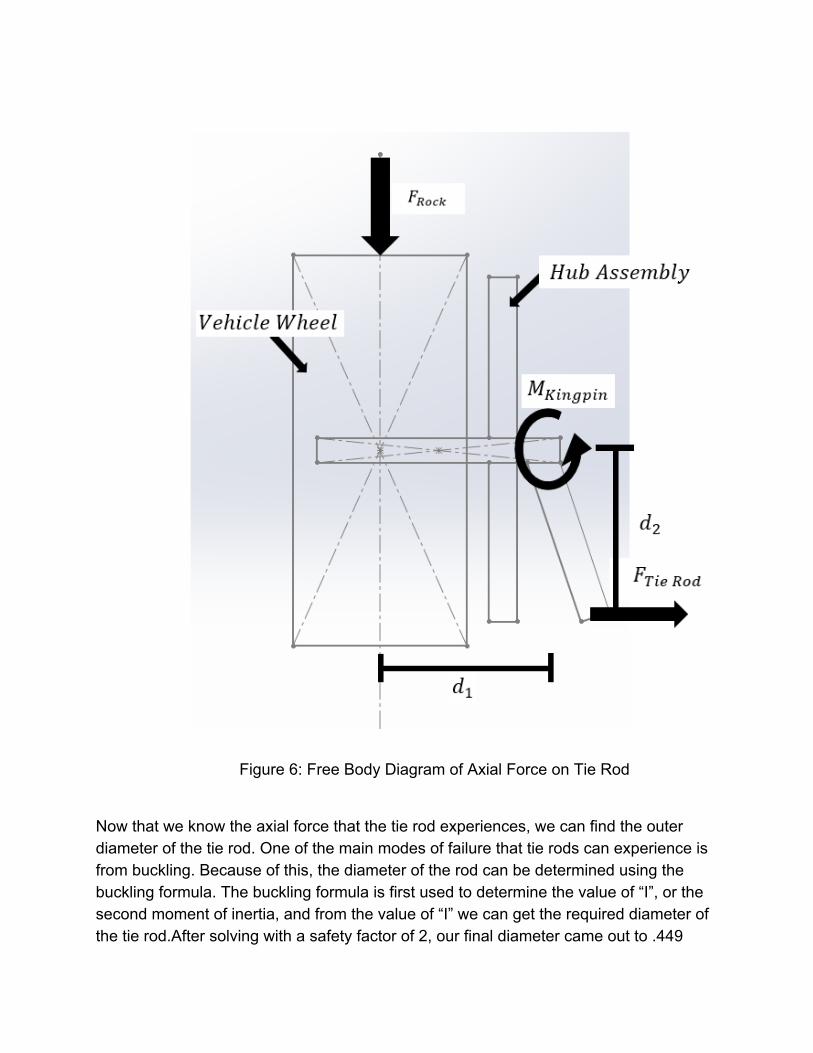
Figure 6: Free Body Diagram of Axial Force on Tie Rod
Now that we know the axial force that the tie rod experiences, we can find the outer diameter of the tie rod. One of the main modes of failure that tie rods can experience is from buckling. Because of this, the diameter of the rod can be determined using the buckling formula. The buckling formula is first used to determine the value of “I”, or the second moment of inertia, and from the value of “I” we can get the required diameter of the tie rod.After solving with a safety factor of 2, our final diameter came out to .449
inches. Due to the fact that tie rods are known to be a weak point on these vehicles the final diameter chosen was .50 inches.
Tie Rod Diameter = .50 inches
Changes to Previous Design 1Link
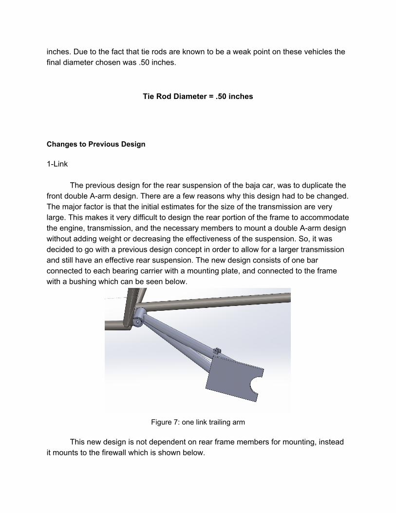
The previous design for the rear suspension of the baja car, was to duplicate the front double Aarm design. There are a few reasons why this design had to be changed. The major factor is that the initial estimates for the size of the transmission are very large. This makes it very difficult to design the rear portion of the frame to accommodate the engine, transmission, and the necessary members to mount a double Aarm design without adding weight or decreasing the effectiveness of the suspension. So, it was decided to go with a previous design concept in order to allow for a larger transmission and still have an effective rear suspension. The new design consists of one bar connected to each bearing carrier with a mounting plate, and connected to the frame with a bushing which can be seen below.
Figure 7: one link trailing arm
This new design is not dependent on rear frame members for mounting, instead
it mounts to the firewall which is shown below.
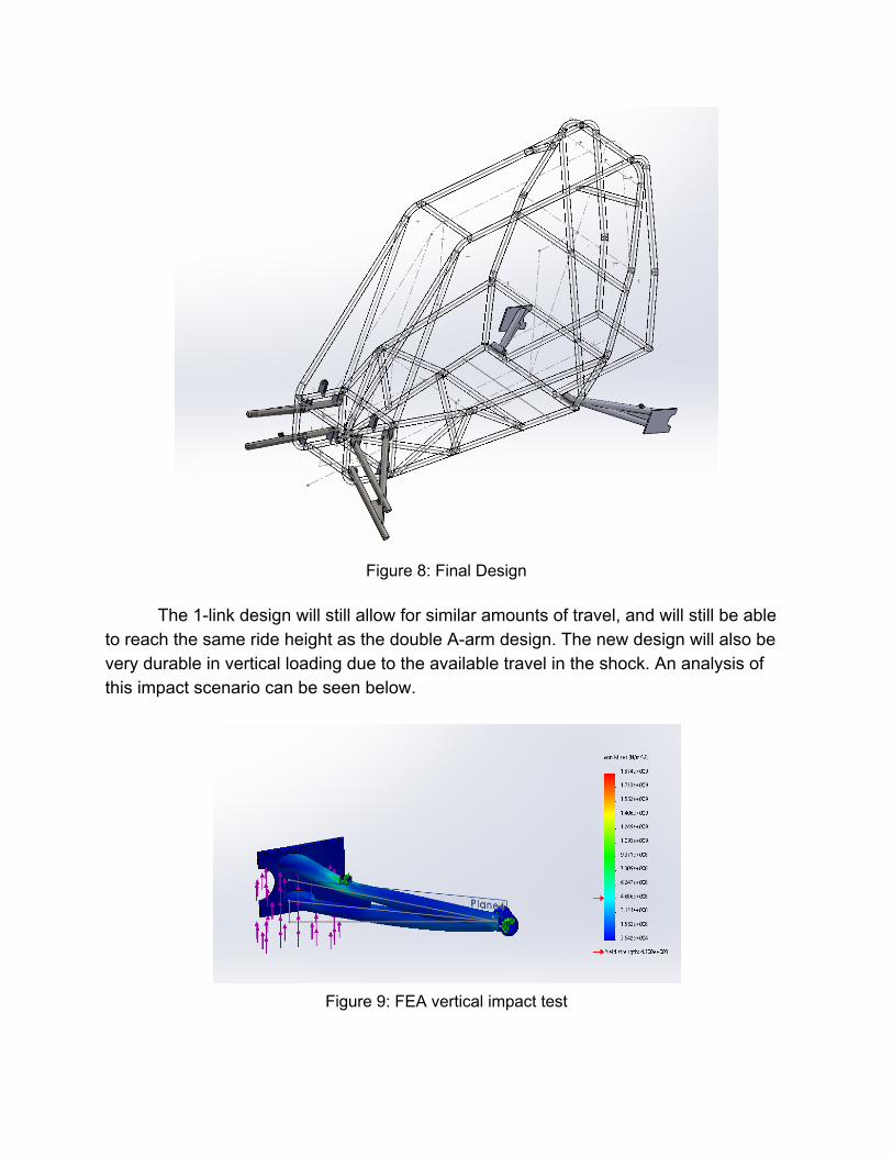
Figure 8: Final Design
The 1link design will still allow for similar amounts of travel, and will still be able
to reach the same ride height as the double Aarm design. The new design will also be very durable in vertical loading due to the available travel in the shock. An analysis of this impact scenario can be seen below.
Figure 9: FEA vertical impact test
This scenario simulates a two foot fall on a rear wheel. As you can see, the only area of high stress is located around the shock mounting point. This is because the scenario simulates the shock being fully compressed, a situation that the car will not see because the frame will bottom out before the shock does. Also, this simulation is extreme because it assumes only one wheel will take the force of the impact when in reality at least two wheels will share it. The 1link design, when compared to the double Aarm design, is weaker in a side impact. This is because it has minimal horizontal support. An analysis of a similar side impact scenario can be seen below.
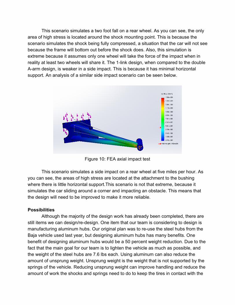
Figure 10: FEA axial impact test
This scenario simulates a side impact on a rear wheel at five miles per hour. As
you can see, the areas of high stress are located at the attachment to the bushing where there is little horizontal support.This scenario is not that extreme, because it simulates the car sliding around a corner and impacting an obstacle. This means that the design will need to be improved to make it more reliable. Possibilities
Although the majority of the design work has already been completed, there are still items we can design/redesign. One item that our team is considering to design is manufacturing aluminum hubs. Our original plan was to reuse the steel hubs from the Baja vehicle used last year, but designing aluminum hubs has many benefits. One benefit of designing aluminum hubs would be a 50 percent weight reduction. Due to the fact that the main goal for our team is to lighten the vehicle as much as possible, and the weight of the steel hubs are 7.6 lbs each. Using aluminum can also reduce the amount of unsprung weight. Unsprung weight is the weight that is not supported by the springs of the vehicle. Reducing unsprung weight can improve handling and reduce the amount of work the shocks and springs need to do to keep the tires in contact with the
ground over uneven terrain. We can also reduce the rotational mass of the hub assembly, which can improve acceleration and braking. Also, machining the aluminum hubs should not be an issue, because we have the tools capable to do so. There are a few drawbacks though. One drawback is that the aluminum needed for the hubs is expensive, and might not be within budget. Finally, another drawback is that the fatigue life is much shorter than the fatigue life of the steel hub. This could mean that the hub will only last through 2 years of competition use.
Another possibility for the team is to minimize the track width of the vehicle. Minimizing the track width could be needed to make sure that the front of the vehicle is the same width as the rear. One benefit to reducing the track width is that the steering angles to achieve the desired turning radius would be reduced. Another benefit is that the maneuverability of the vehicle will increase. With the vehicle width decreased, we will have the ability to maneuver through tight tree and boulder gaps. Although there are multiple benefits, there are also some disadvantages. One disadvantage is that the vehicle will display less stability. Another disadvantage is that the probability of rolling the vehicle increases. Since the vehicles frame and center of gravity are relatively high, decreasing the track width could cause the vehicle to overturn with less force. Futures Tasks
The next step in the process this semester is to order the necessary parts to complete the suspension and steering. Uniball and heim joints needed to be ordered from our supplier Viking Performance. Bolts and fasteners will be ordered from Copper State. Materials for the steering such as tierod and Kingpin adjustment plates need to be ordered from Industrial Metal Supply. This material is not needed right away because the steering will be built after suspension is complete.
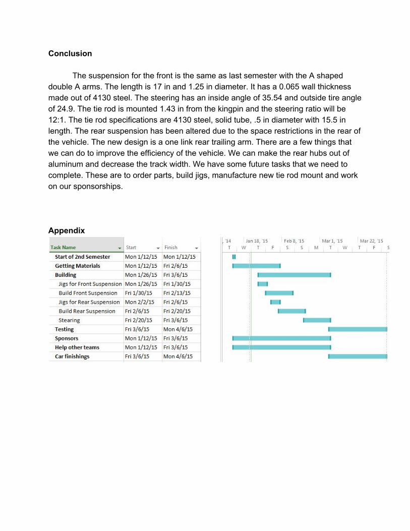
The jigs for the front suspension can begin to be built. Once all materials for front suspension arrive the build of front members can begin. After the front suspension is complete the rear jigs and members can be manufactured. The team is planning on having the suspension and steering built and assembled by the beginning of March; after which we can help the other teams and putting the finishing touches on the rest of the vehicle.
One major obstacle for each team is money. This vehicle cost around ten to fifteen thousand dollars to build and as of now we only have two thousand. For this reason we need to raise as money as possible by getting in contact will companies to see if they would like to sponsor our vehicle. This means going to as many companies as we can think of to receive funds.
Conclusion
The suspension for the front is the same as last semester with the A shaped double A arms. The length is 17 in and 1.25 in diameter. It has a 0.065 wall thickness made out of 4130 steel. The steering has an inside angle of 35.54 and outside tire angle of 24.9. The tie rod is mounted 1.43 in from the kingpin and the steering ratio will be 12:1. The tie rod specifications are 4130 steel, solid tube, .5 in diameter with 15.5 in length. The rear suspension has been altered due to the space restrictions in the rear of the vehicle. The new design is a one link rear trailing arm. There are a few things that we can do to improve the efficiency of the vehicle. We can make the rear hubs out of aluminum and decrease the track width. We have some future tasks that we need to complete. These are to order parts, build jigs, manufacture new tie rod mount and work on our sponsorships. Appendix