safe use of machinery in technology - vcal @...
TRANSCRIPT

Safe Use of Machinery in Technology/Resource Manual/Version 1 Page 1
Safe Use of Machinery in Technology Contents
Basic Static Machine - Radial Arm Saw .....................................................................................7
Basic Static Machine - Surface Planer ......................................................................................22
Basic Static Machine - Rip Saw .................................................................................................42
Basic Static Machine - Panel Planer..........................................................................................64
Basic Static Machine - Band Saw...............................................................................................78
Basic Static Machine - Panel Saw ............................................................................................104
Basic Static Machine - Vertical Drill Press.............................................................................118

Page 2 Safe Use of Machinery in Technology/Resource Manual/Version 1

Safe Use of Machinery in Technology/Resource Manual/Version 1 Page 3
Key Words Abrasive Material that is very hard, has sharp edges, used to wear away a softer
surface.
Anti-Kickback Block A block or stop clamped on the fence or table of a machine to prevent kickback (also known as Limiting Stop or Stop Block).
Arbor Metal shaft or axle on which a cutter block or saw blade is fitted.
Arris The corner or sharp edge where two surfaces meet.
Backing Material, generally paper, cloth or combination of both, which has abrasive grit bonded to it to form a belt or disc.
Back Out To pull the material back towards the operator before the cut has been completed.
Bearing Surface A surface onto which something is pushed or rests.
Belt Name given to a length of backing which has the abrasive grit bonded to it.
Bevel An angled cut that alters the edge of material to other than 90°.
Bow A hollow that may be found in the length of material.
Burn Marks Marks which show on the material because either the blade was blunt or the feed had stopped.
Cabriole Leg The shape applied to legs of Queen Anne furniture
Casting Web Metal rib used for added strength under machine tables.
Clogging To congest, block or choke up.
Close Coat Coated abrasive having abrasive particles bonded closely together.
Check Plate A small plate inserted into the fence of a surface planer to stop material being pushed under it.
Chuck Fixed to the end of the drive shaft. Contains key or hand tightened jaws to hold the bits.
Cutting Circle The circle scribed by the points of the teeth of a saw blade or the extreme cutting edge of cutters when they are secured in the cutter block.
Dressed/Planed All Round (DAR/PAR)
A description of material that has been planed on all surfaces.
Face The larger (wider) surface of material that has been planed straight, flat and free of twist.

Page 4 Safe Use of Machinery in Technology/Resource Manual/Version 1
Face Edge A surface planed at 90° to the face.
Filler Strip Material used to fill a gap.
Flitch A part of a log suitable for further conversion, the rectangular section of which is not less than 300mm x 100mm.
Foot Control A device used to activate the boring cycle of the head.
Gapped A term used to describe a chip taken out of a cutter.
Grain The direction of cells in the structure of timer.
Hopper Funnel-like device used for directing waste material.
Isolate Switch off the main power supply to the machine.
Jig A device used for guiding and/or holding material during a machine operation.
Kerf The width of cut produced by the teeth of a saw blade.
Kickback The throwing back of material by the force of revolving cutters or saw blades.
Lever Stroke Long arm connected to the sanding pad, used on the stroke sander.
Limiting Stop A block or stop used to prevent kickback or to limit the travel of material over or past the cutters.
MDF Medium Density Fibreboard – a type of solid timber substitute board that does not have any grain direction.
Micro Adjustment Small or minute amount of adjustment.
Off-saw A term used to describe material that has been sawn and has not been processed further.
Open Coat Coated abrasive with the grit spaced apart so that soft timer will not clog the belt.
Pneumatic Operated by the force exerted by compressed air.
Push Stick A piece of timber with a birds-mouth shape cut on one end for pushing material through the machine.
Relief Cut The removal of waste material to allow easier access for a cutter or blade.
Ripping Sawing along the grain.
Serrated Grooved or notched.
Shedding Abrasive particles dislodged from the bond.

Safe Use of Machinery in Technology/Resource Manual/Version 1 Page 5
Skew Not straight, angled to the centre line or slanting.
Stock Another name used to describe the material or component being processed.
Streaking Blemished on the sanded surface caused through a clogged belt.
Table Clamp A means of securing stock to the table.
Tailer Out A person who supports material from the outfeed side of a machine.
Tension The amount of pressure placed on the abrasive belt by moving the drums apart. This allows the belt to be driven around the drums.
Test Cut A cut applied to scrap material to test a set up.
Traverse To sand diagonally across a surface.
Trunnion A project support on which a band saw table tilts.
Turret A device used to hold multiple bits on a horizontal drill.

Page 6 Safe Use of Machinery in Technology/Resource Manual/Version 1

Safe Use of Machinery in Technology/Resource Manual/Version 1 Page 7
Basic Static Machine - Radial Arm Saw
Travelling Saw Radial Arm The primary function of a radial arm saw is to square cut solid timber to a given length (basic crosscutting), however the design of the machine allows straight ripping, bevel ripping, trenching, mitre and bevel cutting and compound cuffing as well as a variety of other operations to be carried out. This machine consists of a fabricated steel base which supports a vertical steel column (or pillar), from which a cantilever arm is supported. The saw blade is mounted on the motor shaft and the complete assembly referred to as the saw carriage moves on slides secured to the arm. This carriage moves backwards and forwards along the arm in the horizontal plane and the blade cuts in a straight line. The cantilever arm can be swivelled up to 45 degrees in either direction from a position of ninety degrees to the fence. It can also be raised or lowered on the support column to accommodate a variety of blade sizes, cutting and trenching heads and to control the depth of grooves or trenches when required. A locking device is used to secure the arm in the required position. On some machines the saw carriage can be rotated so that the blade is parallel to the fence and canted (tilted) to 45° in one direction only in order to permit bevel cutting, or if required, compound angles.

Page 8 Safe Use of Machinery in Technology/Resource Manual/Version 1
Parts and their Function – Radial Arm Saw

Safe Use of Machinery in Technology/Resource Manual/Version 1 Page 9
TABLE The table is generally made from timber and should be long enough to provide support for the most common sizes to be cut. When saws are located above the table, it is good practise to provide a replaceable wooden table insert to allow for height adjustment of the blade. This insert can also be replaced to prevent breakout on the under-surface of the material being but. The dovetailed slot to receive the insert can easily be cut with the saw tilted to the right for the first cut and to the left for the second cut. A number of cuts with the blade set at 90° will remove the centre of the slot. Some machines have a roller table as an extension to the timber table. The top of the rollers are level with the surface of the bench. All rollers should run freely and be set at 90° to the line of the fence. The spacing of the rollers is generally about 300 mm to 400 mm apart.

Page 10 Safe Use of Machinery in Technology/Resource Manual/Version 1
BLADE RISE AND FALL HEIGHT ADJUSTMENT HANDLE This adjustment allows for the variation in blade size and for height or depth adjustment when trenching. CROSS CUT SAW BLADES Depending on the type of cuffing to be done, circular cross cut saw blades may have a positive or negative hook/rake of up to 50° to their teeth. Positive rake on a radial arm saw blade tends to make itself feed into the timber which, for obvious reasons, can be potentially dangerous. TRENCHING HEADS Trenching heads have a similar cutting action to a cross cut saw blade, having either thin blades with front bevels on either side of a series of cutters (dado) or sectional cutter components with spur cutter sections on the outer edges, giving the resultant trenches clean edged sides and bottoms.

Safe Use of Machinery in Technology/Resource Manual/Version 1 Page 11
FENCE The fence can be metal, aluminium section or made from timber. It generally runs the full length of the table and is firmly fixed. Provision is often provided for measuring systems or stops. NOTE: After changing blades, the accuracy of the measuring system should be checked to ensure it is accurate. GUARD This protects the section of the blade not cutting the timber and, if adjustable, should be located as close as practicable to the timber being cut. The extension piece is adjustable above the material being cut. Some guards also direct the removal of sawdust to the extraction system.
Blade guard and front extension piece

Page 12 Safe Use of Machinery in Technology/Resource Manual/Version 1
Operational Safety Precautions When operating a radial arm saw: • DO NOT attempt to remove off-cuts or sawdust from the table with your hands when the
saw is running.
• The crown guard extension should be set as close as possible to the top of the timber being cut, and to clear the fence.
• The operator should be positioned out of the direct line of the saw blade at all times.
• DO NOT place your hands in line with the cut.
• The saw should be operated with the hand which does not require the body to be in line with the blade.
• DO NOT force feed the material.
• Keep the table of the machine and the surrounding area clean and free of off-cuts.
• When cutting bowed material, place the round face down onto the table and the round edge against the fence.
• Check that all locks on the machine are tight.
• Never leave material on the radial arm table in line with the saw and away from the fence.
• Always return the saw to a non cutting position after each cut.
• Never leave the saw unattended with the power turned ON.

Safe Use of Machinery in Technology/Resource Manual/Version 1 Page 13
Procedure for Rough Docking to Length on a Radial Arm Saw The power to the machine must be isolated and the ON/OFF switch should be checked to ensure the electricity supply is off. The machine table and the work area surrounding the machine should be clean and free from all off-cuts. • The blade should be checked to ensure it is sharp and suitably positioned to cut through the
material thickness. The blade should also be checked for squareness to the fence and table.
• The crown guard (or hood) must be adjusted as close as possible to the top of the material to be cut. The gap must not exceed 13 mm for safe operation.
• The stop is adjusted to the off-saw size (length) of the material required. As further machining operations are required, then an extra 25 mm allowance is added.
The stop may be set at the required distance by using the graduated scale on the fence, if one is fitted, or alternatively, this is done by measuring from the stop to a tooth which is set (bent) towards the stop, and this distance represents the length of cut.
The stop is locked in this position.
• The material must be checked for bows, twists and for any foreign matter which may be embedded in the surface. The foreign matter must be removed as this may damage the teeth. The spring (or rounded) edge must be placed against the fence and the bowed side placed downwards onto the table.
If the material has excessive spring it may have to be planed straight prior to cutting. If it has a planed face and edge, the edge is positioned against the fence and the face placed downwards onto the table.
• The power is restored and the machine is turned on. When the blade has reached full
revolutions, the face of the material is placed on the table with the edge held firmly against the fence. The blade is then fed into the material.

Page 14 Safe Use of Machinery in Technology/Resource Manual/Version 1
Sliding Carriage This part of the machine carries the saw blade assembly which can be adjusted to take up any slack that may develop in the rollers. The saw spindle is the actual shaft of the motor and the drive is direct. The shaft has a shoulder allowing a flange to be fitted. The end of the shaft is threaded to enable a locking nut to secure the blade and flanges. There are no Vee belts or pulleys and the entire saw assembly is articulated and suspended from the radial arm. Swivel Locking Handle When the blade/trenching head is to be set to an angle, the swivel locking handle is released and the blade assembly tilted to the required angle. Operating Handle This handle is used to bring the saw forwards or to push it backwards. If the handle is fitted on the right-hand side of the saw blade, the handle is pulled with the left hand and the timber held with the right hand or if the handle is fitted on the left-hand side the opposite applies. This method of operation is necessary to prevent the operator being directly in line with the saw blade.

Safe Use of Machinery in Technology/Resource Manual/Version 1 Page 15
ELECTRICAL SWITCHES
Radial arm saws may be fitted with a flush, green ON switch and a red, mushroom-shaped head STOP switch or, alternatively, an ON/OFF rocker switch mounted on the operating handle. Each machine must be fitted with a red mushroom-shaped, EMERGENCY STOP button. This must be of the push and lock-in type to ensure that it is not possible to start the machine until the button has been re-set An isolation switch must be fitted to enable the main power supply to be locked off when maintaining or adjusting the machine. The switches should be placed in an easily accessible position.

Page 16 Safe Use of Machinery in Technology/Resource Manual/Version 1
OPERATING A RADIAL ARM SAW Safety Operators of radial arm saws must be aware of potential hazards which exist when using these machines. The following safety precautions must be observed when operating, setting up and maintaining a cross cut saw. PRE-OPERATIONAL SAFETY PRECAUTIONS Always ISOLATE the power to the machine by turning the isolation switch to OFF before carrying out any adjustments. Check that the main electricity supply has been isolated by pressing the machine’s ON/OFF switch. Clean the surrounding work area and then ENSURE that: • the machine and the surrounding area is clean and free from obstacles and off-cuts
• all guards are correctly positioned and secured
• it a crown guard has an extension piece, it must be positioned as close as practicable to the material being cut
• the riving knife is positioned correctly and secured, if ripping
• the blade is installed with the teeth facing in the correct direction
• the blade has not been damaged
• the blade is sharp
• the blade is square (at 90°) to the table
• the table is free of grit or other foreign material
• the fence is square to the table and locked in position
• the material is cut in the first instance, longer than the pie-set stop. If the material has a split in the end, it should be cut off
• the material is then rotated end for end (1800) and the same edge is placed against the fence. The material is pushed up to the pre-set stop and cut to length
• when the operation has been completed
• all switches must be turned OFF
• the table should be cleared of any off-cuts before the machine is left unattended

Safe Use of Machinery in Technology/Resource Manual/Version 1 Page 17
Procedure for Squaring to Length on a Radial Arm Saw • The power to the machine must be isolated and the ON/OFF switch should be checked to
ensure the electricity supply is off. The machine table and the work area surrounding the machine should be clean and free from all off-cuts.
• The blade should be checked to ensure it is sharp, raised and locked at a suitable height. The fence should be checked for squareness to the blade.
• The crown guard (or hood) must be adjusted as close as possible to the top of the material to be cut.
• The stop is adjusted to the required finished size of the material.
• This may be set at the required distance by using the graduated scale on the fence, or alternatively, may be done by measuring from the stop to a tooth which is set (bent) towards the stop, and this distance represents the length of cut.
The stop is locked in this position.
• The power is restored and the machine is turned on. When the blade has reached full revolutions, the material is placed on the table with the face up and edge held firmly against the fence.
NOTE: At no time should hands be placed in line with the blade or any closer than 200 mm to it.
• Make a trial cut to check the accuracy of the stop position, adjust if necessary. Use scrap material, large enough for safety, for this operation.
• Make a trim cut on one end of material to ensure squareness.
• The material is then rotated end for end (180°) and the same edge is placed against the fence.
The material is then cut right through and both pieces (the required material and the off-cut) are carefully removed.
• When the operation has been completed:
a) AR switches must be turned OFF
b) The table should be cleared of any oil-cuts before the machine is left unattended
Procedure for Angle Cutting on a Radial Arm Saw A) TO THE EDGE B) TO THE FACE • The power to the machine must be isolated and the ON/OFF switch should be checked to
ensure the electricity supply is off. The machine table and the work area surrounding the machine should be clean and free from all off-cuts.
• A false table and fence should be secured to the existing table to prevent damage.

Page 18 Safe Use of Machinery in Technology/Resource Manual/Version 1
• The blade should be checked to ensure it is sharp and suitably positioned to cut through the material thickness.
a) the blade angle should be checked for accuracy to the fence. b) the blade angle should be checked for accuracy to the table.
• The crown guard (or hood) must be adjusted as close as possible to the top of the material to be cut. The gap must not exceed 13 mm for safe operation.
• The stop is adjusted to the length of the material required.
The stop may be set at the required distance by using the graduated scale on the fence, if one is fitted, or alternatively, this is done by measuring from the stop to a tooth which is set (bent) towards the stop, and this distance represents the length of cut.
• The power is restored and the machine is turned on. When the blade has reached full speed, make a trial cut of the angle on scrap material and adjust angle if required.
• Make a trial cut of the length required and adjust stop if necessary.
NOTE: The operator must stand out of direct line of the blade when cutting into the material in case of jamming. At no time should hands be placed in line with the blade nor any closer than 200 mm to it.
• Cut material to specified angle:
a) to the edge
b) to the face
• When the operation has been completed:
a) all switches must be turned OFF
b) the table should be cleared of any off-cuts before the machine is left unattended
Angled to the edge Angled to the face

Safe Use of Machinery in Technology/Resource Manual/Version 1 Page 19
Procedure for Compound Angle Cutting on a Radial Arm Saw • The power to the machine must be isolated and the ON/QFF switch should be checked to
ensure the electricity supply; is off. The machine table and the work area surrounding the machine should be clean and free from all off-cuts.
• A false table and fence should be secured to the existing table to prevent damage.
• The blade should be checked to ensure it is sharp and suitably positioned to cut through the material thickness.
• The blade angle should be checked for correct angle to the fence. The blade angle should be checked for correct angle to the table.
• The crown guard (or hood) must be adjusted as close as possible to the top of the material to be cut. The gap must not exceed 13 mm for safe operation.
• The power is restored and the machine is turned on. When the blade has reached full revolutions, make a trial cut of the angles on scrap material and make adjustments if required.
NOTE: The operator must stand out of direct line of the blade when cutting into the material in case of jamming. At no time should hands be placed in line with the blade nor any closer than 200 mm to it.
• Cut material to specified angles to the edge and face.
• When the operation has been completed:
a) all switches must be turned OFF b) the table should be cleared of any off-cuts before the machine is left unattended

Page 20 Safe Use of Machinery in Technology/Resource Manual/Version 1
Procedure for Trenching on a Radial Arm Saw A) SQUARE TO FACE AND EDGE B) ANGLED ACROSS FACE C) COMPOUND ANGLED
• The power to the machine must be isolated and the ON/OFF switch should be checked to
ensure the electricity supply is off. The machine table and the work area surrounding the machine should be clean and free from all off-cuts.
• A false table and fence should be secured to the existing table to prevent damage.
• The selected trenching head should be checked for sharpness before being installed onto the spindle shaft.
• The trenching head must now be set to cut into the material to the required depth. This may be checked by placing a line on the end of the material to be cut, equal to the required depth. The trenching head can then be rotated against this line and adjusted to ensure the correct cut. A test piece of the same thickness should be run to further check the accuracy of the setting.
• Depending on the trench requirement, the following angle set up is necessary:
a) for normal trenching, check trenching head is cutting square to the fence and table b) for angle trenching, check trenching head for correct angle from fence c) for compound angle trenching, check trenching head for correct angle from fence and table
• The crown guard (or hood) must be adjusted as close as possible to the top of the material to
be cut. The gap must not exceed 13 mm for safe operation.
• The stop may be set at the required distance by using the graduated scale on the fence, if it has been re-calibrated to the trenching head, or alternatively, this is done by measuring from the scribing cutter to the stop. This distance represents the position of the trench in relation to the end of the workpiece
• The power is restored and the machine is turned on. When the head has reached full revolutions, a test piece should be run and adjustments made if required.
NOTE: The operator must stand out of direct line of the head when cutting into the material in case of jamming. At no time should hands be placed in line with the head nor any closer than 200 mm to it.

Safe Use of Machinery in Technology/Resource Manual/Version 1 Page 21
• Cut trenches to specifications, eg:
a) square to face and edge
b) angled across face
c) compound angled
• When the operation has been completed:
a) all switches must be turned OFF
b) the table should be cleared of any off-cuts before the machine is left unattended

Page 22 Safe Use of Machinery in Technology/Resource Manual/Version 1
Basic Static Machine - Surface Planer
Surface Planer Single Cutter Block Surface Planing machines are made in a large variety of sizes from small bench mounted models to large production units. Consisting of a base or frame which supports the adjustable infeed and outfeed table and a cutter block situated between these tables, the surface planer operates on the principle of rotary cutting. Machines with long wide tables are designed to surface heavy, and long materials, whilst those with shorter tables are designed for shorter, lighter surfacing operations. The surface planer plays an important part in the overall process of material preparation because any faults left after planing will be irreversible.

Safe Use of Machinery in Technology/Resource Manual/Version 1 Page 23
The main function of a Surface Planer is to prepare a face and face edge on material. A face is the widest surface which is planed straight, along its length, flat and free of wind (twist in the material length). The face edge is the smaller surface and is planed square (at 90°) to the face. The material is placed with the surface to be planed on the infeed table and is then passed over the revolving cutter block. After leaving the cutter block the material rests on the outfeed table which provides support for the completed cut. This method of passing the material over the cutters is described as “Feeding” and the speed at which it passes is called “Rate of Feed”. This is very important in producing a good quality surface finish. General surfacing is done by hand feed, but power feed options are available. Pressure springs offer an alternative method or providing downward pressure and a fence (adjustable guide) is usually fixed at right angles to the table or it may be tilted for special operations. A rebating table or side table is an optional extra on most machines.

Page 24 Safe Use of Machinery in Technology/Resource Manual/Version 1
TABLES The surface planer is fitted with two tables, known as, the infeed and the outfeed table. These are rectangular, flat, machined, cast iron surfaces. Their main function is to support the material during the planing process and it is necessary for the tables to always remain parallel to each other regardless of what operation is being performed. The tables, which may be raised or lowered independently of each other, are fined on either side of the cutter block. The infeed table faces the direction of the cutter block rotation and is lowered to increase depth of cut. For general machining the outfeed table must be exactly level with the cutters at their highest point of revolution but may be lowered for special machining. Usually, these tables are machined to fit into inclined or sloping slides, and are raised/lowered by hand wheels, levers or hydraulics. Each table is fitted with a locking device. The length of the table determines the level of accuracy to which the material may be planed safely. Long material will drop off the outfeed table and become difficult to hold down onto the cutters. Table lengths vary from 1.1 metres to 2.5 metres and may be between 150 mm and 500 mm wide. The rebate table and fence housing are fixed to the infeed table.

Safe Use of Machinery in Technology/Resource Manual/Version 1 Page 25
The rebate table is bolted to the edge of the infeed table and projects past the cutter block with a small clearance between it and the outfeed table. Its use makes rebating easier, more accurate and safer. Generally this table is an optional extra.

Page 26 Safe Use of Machinery in Technology/Resource Manual/Version 1
The fence is a flat, machined casting which is used to support the timber and guide it over the cutter. It is fitted to a bar which slides through a bracket attached to the right-hand side of the infeed table. This allows the fence to be moved and locked in position across the planer tables. Some fences on small machines are fixed into a guideway on the end of the infeed table. The fence is moved along this guideway to locate it at the required position across the table.
Fence Gauge The fence extends over the infeed table, the cutter block, and a short distance over the outfeed table. For general surfacing the fence must be set at 90° to the infeed table but in order to bevel or chamfer the edge of stock, the fence may be tilted up to 45°. The portion of the fence that extends over the outfeed table may have an adjustable plate to provide support for thin timber. This plate, when provided, should be set as near as possible to the table to prevent the material being pushed beneath the fence. The fence may also have mounting positions for springs and shaw guards. GUARDS Guards are generally metal covers or hoods designed to cover the cutter block and moving parts to ensure the safety of the operator. There are two main guards covering the cutter block on a surface planer. These are known as:
• front guards • back guards

Safe Use of Machinery in Technology/Resource Manual/Version 1 Page 27
Front Guards These are mounted on the left hand or working side of the infeed table and cutter block. There are two main types of front guards used on the surface planer. These are:
• the bridge guard • the leg of mutton guard
Bridge Guard The bridge type should be adjusted to completely cover the cutters at all times. A rise and fall movement is provided to accommodate variations in the thickness of material.. When surfacing and edging, the gap between the bridge guard and the timber being surfaced must not exceed 10 mm. The gap between the fence and bridge guard must not exceed the thickness of the timber plus 10 mm to prevent the operator’s fingers from coming in contact with the cutters.

Page 28 Safe Use of Machinery in Technology/Resource Manual/Version 1
Leg of Mutton Guard The leg of mutton guard is self adjusting and can only move horizontally. It is activated by the force of the material pushing against it when the material moves forwards over the cutter block. At the Completion of the cut, the guard returns to its original position by means of a return spring.
Rear Guard These are fixed to the non-working side of the fence and automatically cover the cutter block regardless of the position of the fences on the table.

Safe Use of Machinery in Technology/Resource Manual/Version 1 Page 29
These are fixed to the non-working side of the fence and automatically cover the cutter block regardless of the position of the fences on the table.
Surface planers must be fitted with a flush green ON switch and a red mushroom shaped head STOP switch. Alternatively, a two stage Star Delta rotary start switch, having three positions (OFF, START or RUN) may be fitted, to prevent the motor from overloading when starting. All machines must be fitted with a red ‘mushroom’ shaped push EMERGENCY STOP button. This must be of the lock in type ensuring that it is not possible to start the machine until the button has been re-set. An isolation switch must be fitted to lock off the main power supply when maintaining or adjusting the machine. The switches should be placed in an easily accessible position.

Page 30 Safe Use of Machinery in Technology/Resource Manual/Version 1
CUTTERS Cutters may be high speed steel, hard carbide, combination high speed/tungsten turn knives.
High Speed Steel Cutters Cutters which may be re-sharpened are flat, generally about 4 mm thick, 30 mm wide, have a bevel ground on one edge of about 350 and their length is the same as the width of the table. The number of cutters held in the block may vary from 2 to 6. Cutters fitted at an angle in their length do not cut the full width of the material at the same time, and a shearing cut results. Such a cutting action is smoother and reduces the risk of the material being knocked from the operator’s hands. Cutter Marks
Wedging cutting action of rotary planing

Safe Use of Machinery in Technology/Resource Manual/Version 1 Page 31
The action of the cutters or knives striking the timber when held in the cutter block may be described as a wedging action.
Hollows Produced By Rotary Cutting Action When two or more cutters are mounted on a cutter block, which rotates at high speed, the cutters have an intermittent cutting action caused by the gap between each cutter striking the material. This action is described as rotary planing, and produces a series of ridges and hollows across the material. The distance between each ridge is called a cutter mark and these have a great influence on the final finish of solid timber if it is to be painted or polished. The size of the cutter marks is affected by four factors:
• cutter block speed • feed speed • number of cutters • correct cutter setting

Page 32 Safe Use of Machinery in Technology/Resource Manual/Version 1
SAFETY The following safety precautions must be observed when operating, setting up and maintaining a surface planer. Pre-Operational Safety Precautions Always isolate the main power to the machine by turning the isolation switch to OFF before carrying out any adjustments. Check that the electricity supply has been disconnected by pressing the machine’s ON/OFF switch. Clean the surrounding work area and then ensure that: • the cutters are sharp and free of cracks or chips • the outfeed table has been set to the cutting circle for general surfacing • the cutter block or cutters are guarded behind the fence • the leg of mutton guard operates so that the spring action will always allow the guard to
cover the cutters or the bridge guard is set to within 10 mm of the material being planed • the depth of cut set for general surfacing does not exceed 2 mm • the fence is in the locked position prior to starting the machine
Operational Safety Precautions The following safety precautions must be observed to ensure the safe operation of the surface planer: • Adopt a safe, comfortable stance to enable full control of the operation. • Maintain a firm grip on the material and always keep hands on the top surfaces. NEVER
place hands or fingers on the trailing or rear end of the material. • Material that is less than five times the distance between the lip of the infeed and outfeed
table must not be planed. • Check that the material is free of splits, metal particles and loose knots. • Plane timber with the grain to prevent kickback. • Avoid making dangerously deep cuts, but take several lighter cuts instead. • Use push blocks when planing short or thin timber. • Re-set the machine for general surfacing after completing stopped work, rebates or bevels.

Safe Use of Machinery in Technology/Resource Manual/Version 1 Page 33
Material Characteristics Affecting Surface Finish Even though cutters may be sharp, it is necessary to remember that there are many varieties of timber and substitute boards, each having different working characteristics. Timber is a fibrous material in which the cells lie in layers that are not necessarily straight or face in the same direction. The direction of the cells is called the grain. The fibres often lay in curved paths and circle around knots and other timber defects. When timber is machined, the grain is usually cut at an angle, thereby exposing the ends of the fibres. Consideration must be given to any other peculiar characteristics of substitute boards which could cause severe blunting and chipping of the cutters. Machining material having silicon deposits will cause more frequent need to change the cutters, or could require the use of tungsten tipped cutters. GRAIN DIRECTION Whilst difficult to describe, grain direction of solid timber plays an important part in quality control. The wedging action of a rotating planer knife requires planing with the grain to achieve the best finish. Grain direction may be determined in two ways: • by feel • by observation Feel Being able to determine grain direction in solid timber comes mainly with practice. If timber is rough, moving the hand over the surface to be planed will help to feel the grain. Moving with the grain will feel smooth whilst moving against the grain will feel rough. This may be compared with short haired dogs or cats. In one direction the hair feels smooth, whilst in the other direction the hair is raised and feels rough. If difficulty is found feeling the grain direction on the surface to be planed, moving the fingers along the sharp edge (arris) formed where the edge of the timber meets the side (face) may prove to be easier.

Page 34 Safe Use of Machinery in Technology/Resource Manual/Version 1
Observation If the direction of the grain cannot be determined by feel, then there are several other characteristics which may be identified.
Features Of The Grain Which Help Determine Grain Direction Vessels or pores cut through on the surface of solid timber usually appear in the shape of a teardrop. The pointed end of the teardrop is the direction of the grain. It is possible to pick the grain as the teardrop shaped pores appear deep at one end and taper to the surface to a point at the other end. The grain direction is the way that these pores exit the timber surface, eg the narrow part of the teardrop. On the edge of the timber the growth rings may appear as dark lines. These lines may be straight along the edge or they may be angled. If they are angled, they will point towards the surface to be planed (face). The direction of the grain is the direction these lines exit the surface. By observing the shape of the growth rings on the end of the timber, it may be found that they curve up towards the surface to be planed (face). On this surface, these growth rings converge and may appear as narrow pointed ends or loops. The direction of the grain is in the direction these points or loops converge.

Safe Use of Machinery in Technology/Resource Manual/Version 1 Page 35
A machinist must determine the grain direction in order to place the timber on the machine correctly and to cut with the grain.
Cutting With the Grain A cutter which revolves in the direction shown in the above diagram is said to cut with the grain.
Cutting Against the Grain A cutter which revolves in the direction shown in the above diagram is said to cut against the grain. The machinist must also consider the shape of the timber, whether it is bowed or twisted by the effects of seasoning and the position of defects such as knots and wavy edges.

Page 36 Safe Use of Machinery in Technology/Resource Manual/Version 1
PLANING PRINCIPLES When operating a surface planer there are a number of principles and material characteristics that must be observed. The following planing principles should be observed during any operation on the surface planer: • the full width of cutters should be used to evenly distribute their wear • a controlled and even rate of feed will ensure a good finished surface • for material that will require sanding and fine finishing there should not be less than eight
cutter marks per 25 mm • for material used in construction applications, there should not be less than five cutter marks
per 25 mm • the far right of the cutters should be used to plane abrasive type materials as this will keep
the rebating edge sharp. Material characteristics affect the safe operation of the machine and also the quality of finish. Planing a Face and Face Edge The purpose of planing a face and edge on the material before further operations are undertaken, is to provide straight, flat reference surfaces. The reference surfaces produced on a surface planer will provide the accurate basis for other machining operations. It is most important for the edge to be exactly 90° to the planed face. Faults that remain in the material at this stage cannot be corrected in following machine operations. Edge Planing of Plywood and Solid Timber Substitute Boards The abrasive nature of the glue lines in plywood and chipboard have a severe blunting effect on cutters. For this reason when edge planing these materials, the material should be kept well over to the right of the cutter (the pulley side of the cutter block). This will leave the rest of the cutter sharp for machining less abrasive materials.

Safe Use of Machinery in Technology/Resource Manual/Version 1 Page 37
Procedure for Planing a Face and Face Edge The Pre-Operational Safety Precautions must be observed before attempting this procedure. Planing a Face (General Surfacing) 1. The main power to the machine must be isolated. The machine’s ON/OFF switch is checked
to ensure that the electricity supply has been disconnected. The surrounding area should be clean and free of off-cuts and the cutters should be checked to make sure that they are sharp and free of gaps.
2. The fence should be adjusted for the width of the material, rocked in position and Checked for squareness. The guard is set to suit the cut. It should be 5 to 10 mm above the top surface of the material and when the material is placed on its edge against the fence there should be only sufficient gap to allow the material to pass between the guard and the fence.
3. The material must be examined to check for straightness. If it is bowed or twisted, the hollow or twisted side must be placed down on the table. The direction of the grain on the proposed face side must also be determined. The grain must point away from the direction of the rotation of the cutter block when the face is placed on the table.
If the material is not bowed or twisted, the best side is selected as The grain direction is determined on the side to be planed.
4. The power is restored to the machine and the material is placed on to the infeed table with the hollow surface to the table.
Both hands within the surface area of the material, with light pressure downward
Left hand flat on material and use a push pad to drive material across the cutter head
5. Light hand pressure is applied on the upper-most surface and the material is fed over the cutters.
The right hand must always be on top of the material and never be placed behind the trailing end.

Page 38 Safe Use of Machinery in Technology/Resource Manual/Version 1
6. With both hands flat on the material and contained within it, and drive the board across the cutter head at a regular feed rate.
7. Steps 4, 5 and 6 are repeated until the surface has been planed straight, flat and free from twist. This now becomes the face and the main reference surface for planing a face edge.
Planing a Face Edge Before planing a face edge it is important to ensure that the fence is square (at 90°) to the table.
Face of the material placed against fence and edge placed onto table
8. The edges of the material are inspected and if one is bowed this will be the proposed face edge.
The hollow edge is placed down on the infeed table and the face is placed against the fence. If the material is solid timber and it does not have a hollow edge then the grain direction on the edge to be planed must point away from the rotation of the cutters.
Pressure must be applied to the material to hold ft against the fence as well as down on the table. It is extremely important to ensure the material is held firmly against the fence and only a light downward pressure applied when the material is moved over the cutters. If the pressure applied downwards exceeds the pressure against the fence the material may rest on the table or the unplaned edge. Because this edge is generally not square to the face, the result will be that the planed edge will also be out of square to the face.
9. When planing, the left hand directs the position of the material and holds it against the fence while the right hand is used to push feed the material over the cutters at a constant rate.

Safe Use of Machinery in Technology/Resource Manual/Version 1 Page 39
NOTE: Both hands must remain on top of the material at all times and the right hand must NEVER be placed behind the trailing end. The fingers on one face with the thumb on the other, as illustrated above, prevents the hands from slipping either down or across the work piece.
10. Steps 8 and 9 are repeated until a straight edge, square to the face, has been achieved.
11. All switches must be turned OFF, the machine isolated and when the cutters stop revolving the machine table cleared of any off-cuts before the machine is left unattended.
Moisture Content The moisture content of solid timber has a considerable impact on the surface finish, particularly in softwoods. Feed speed, cutter sharpness and grain direction may all have been considered, but often after surfacing softwoods the surface feels rough. This is because the harder growth rings are compressed and later recover creating an uneven surface. This result is described as ‘woolly grain”. Short Material When it is necessary to plane short material, it should be left in lengths made up of two or more pieces and cut to length after it is dressed. This makes the planing operation safer and faster because the operator’s hands are further away from the cutter and less pieces need to be handled.
Minimum length of material is the table opening multiplied by 5 or 300mm which is the minimum distance between rollers on the panel planer.

Page 40 Safe Use of Machinery in Technology/Resource Manual/Version 1
Push block used on Short Material Push blocks can be used to assist the planing of a face on short material. However, the bridge guard will have to be adjusted across to allow the push block access over the cutters. The guard should be set as close as possible to the edge of the push block. A simple method for determining the shortest length that should be passed over the cutters is to lower the infeed table to the required depth of cut, measure the distance from the lip of the infeed table to the lip of the outfeed table and multiply the distance by five. No material should be passed over the cutters by hand if under the calculated size. Fence Square To obtain an edge at 90° to the face of the stock it is important to have the fence square to the table. This is achieved by using a try square. The stock is placed on edge on the table with the blade against the fence. The fence can be adjusted so that the face is parallel to the blade of the tri-square.

Safe Use of Machinery in Technology/Resource Manual/Version 1 Page 41
Hollowed or Bowed Timber
Hollow surface placed down onto the Infeed Table Timber which is bowed in its length will appear to either rock end to end or have a hollow in the centre when it is placed flat on the machine table. The hollow must be placed down on the table so that the first cut removes material from the ends only. This process is repeated until a cut is made on the full length of the material. The feed pressure should be applied in such a way that the hollow is planed out and not pressed out. If too much downward pressure is applied the material will be bent flat and the hollow will remain when the cut is completed. Twisted Timber Timber which has twisted during seasoning will rest on opposite corners and has a tendency to rock (when it is laid on a flat surface). Material of this nature must be planed carefully with the operator holding or balancing the material, so that the first cut removes material from opposite corners. This process is repeated until a cut is made on the full length of the material.

Page 42 Safe Use of Machinery in Technology/Resource Manual/Version 1
Basic Static Machine - Rip Saw
Introduction Circular Rip Saw The Circular Rip Saw Bench is available in a variety of sizes and types. They possess similar fundamental features and all have a frame or base on which a table is mounted, an arbour or saw spindle and a motor. The primary operational function of a rip saw is to cut material to a given size along its length. This involves:
Cutting to width, known as “Flat Cutting”
Cutting to thickness, know as “Deep Cutting”
Angle cutting (or angular cutting) in certain circumstances

Safe Use of Machinery in Technology/Resource Manual/Version 1 Page 43
Machine Parts and their Function
TABLE The table is a flat machined cast iron surface extending the full length and width of the machine. It has a slot for blade projection with a removable section, known as a gap plate, to enable the blade to be easily changed. A wooden throat piece may be fitted at the infeed end of the saw slot to reduce the gap size at the front of the blade to a minimum.

Page 44 Safe Use of Machinery in Technology/Resource Manual/Version 1
The front fence plate has a curve shaped on the end nearest the blade. This curve follows the shape of the blade at the front and is known as the toe of the fence. The base of the toe must be set in line with the base of the gullets of the teeth at table level when the blade is at its highest position. On machines which accept different diameter blades the front plate of the fence must be adjusted so that the toe is in line with the gullet at all times. If the toe is positioned past the gullet the material is held between the fence and the blade after cuffing and may cause the material to bind or unduly rub on the blade. If the toe is set in front of the blade the material will leave the fence before the cut is completed and the material will no longer be supported. Graduated Scale and Fine Adjustment Knob

Safe Use of Machinery in Technology/Resource Manual/Version 1 Page 45
A groove, or slideway, may be milled in the top of the table from front to back, parallel to and left of the blade. This allows a mitre or cross cut fence to be used. (Some machines may have a table groove on both sides of the blade). A guide bar is attached to the front edge of the table (the infeed side) parallel to the edge of the table to allow for a sliding fence. Rise and Fall Adjustment The hand wheel is used to raise and lower the blade above the table. A locking device either in the centre of the wheel or on the side of the shaft locks and unlocks the hand wheel; this holds the blade at the required height. FENCE A rectangular metal fence is located on a guide bar which is attached to the front of the table and its function is to guide the material during the cutting process, to achieve a straight cut. When set for operation, the fence must be square to the table and parallel to the blade. It may be adjusted sideways at right angles to the front of the table to the right of the saw blade and may be locked in position at the desired distance. Fences are generally made in two parts having a front and a back plate. The front plate may be adjusted forwards or backwards and is connected by bolts which slide in slots in the back plate. Some fences are fitted with a graduated scale and a fine adjustment attachment (micro adjustment) on the guide bar to allow very accurate settings to be made. Some fences may also be tilted up to 45° for angle cutting.

Page 46 Safe Use of Machinery in Technology/Resource Manual/Version 1
BLADES Circular saw blades are made from quality steel plate and are perhaps the most highly stressed of all tools when in use. They are made thin in section but large in surface area and are subject to continuous deflection, intermittent shock loading and rapid, unequal changes in temperature. The metal used in their manufacture must be able to hold a cutting edge for long periods, be soft enough to file, ductile, for spring setting of the teeth and tough enough to hold tension. It must also be able to be brazed for the fitting of hardened tips such as tungsten carbide. Blade Types The two types of blades most commonly used in a rip saw are: • spring set plate blades • tungsten carbide tipped blades Spring Set Plate Blades These are blades manufactured from a cast steel plate containing carbon steel alloys. They are ground, tempered, gulleted, tensioned and the teeth are set and sharpened. The blade’s thickness is measured in millimetres and is referred to as the gauge. This may be standard for specific diameters but is generally required by distributors when ordering new blades. Tungsten Carbide Tipped Blades A shaped tip of Tungsten Carbide is brazed to the front of each tooth of a high quality plate steel blade. Tungsten Carbide tips are very hard, have a longer wearing life and remain sham longer than spring set plate blades. These blades were originally introduced to solve the tough sawing problems encountered when cutting abrasive timbers and solid timber substitute boards. Conventional spring set plate blades suffered rapid blunting quick wear and dulling of the points of their teeth.

Safe Use of Machinery in Technology/Resource Manual/Version 1 Page 47
GUARDS Guards may be made of metal, alloy, or fibreglass. They are designed to cover the blade, belts and pulleys to ensure the safety of the operator. The moving parts housed in the frame may be enclosed in a metal box which is shaped to act as a hopper as well as a guard. The shape and size of these vary from manufacturer to manufacturer. They also enclose the portion of the blade below the table and may be referred to as a fixed enclosure guard. There are however, only two types of guards (which meet the Australian Standards) that can be used to cover the top portion of the saw blade on a rip saw or a circular saw. These are: • crown guard (or hood guard) • self-adjusting guard Either one of the above guards must be positioned above the blade at all times when the machine is operated. Crown Guard

Page 48 Safe Use of Machinery in Technology/Resource Manual/Version 1
The crown guard is supported by a vertical and a horizontal post. It can be adjusted upwards and downwards on the vertical post until the space between the guard and the table suits the material to be cut. The vertical post can also be swivelled clear of the table to allow the blade to be removed. Some guards may be fitted with a hinged side gate which enables the fence to be positioned close to the blade for ripping narrow material. A small movable extension piece may also be fitted to the front of the guard. This can be adjusted independently and its function is to guard the exposed portion of the saw blade between the timber and the crown guard to ensure the safety of the operator. The distance between the crown guard and the material to be cut should not exceed 13mm. Self-Adjusting Guard This is a movable guard, fixed to the riving knife and adjusts itself up and down to accommodate the passage of the material underneath. The guard covers the blade until actuated by the movement of the material. It is designed to rise as the material moves underneath at the beginning of the operation and to return to its original position on completion of the operation. A variation of this type of guard is one shaped as a crown guard. This is also fixed to the riving knife but it is not self-adjusting. This guard is fixed in a permanent position above the material and leaves the front of the blade exposed when ripping thin material.

Safe Use of Machinery in Technology/Resource Manual/Version 1 Page 49
Electrical Switches
Rip saws must be fitted with a flush, green ON switch and a red, mushroom - shaped-head STOP switch. Alternatively, a two stage Star Delta rotary start switch, with positions for OFF, START and RUN may be fitted. All machines must be fitted with a red, mushroom shaped EMERGENCY STOP button. This must be of the push and lock-in type to ensure that it is not possible to start the machine until the button has been re-set. An isolation switch must be fitted to enable the main power supply to be locked off when maintaining or adjusting the machine. All switches should be placed in an easily accessible position.

Page 50 Safe Use of Machinery in Technology/Resource Manual/Version 1
Riving Knife Hand fed rip saws must be equipped with a spreader known as a riving knife. It is fixed below the machine table, behind and in line with the saw blade and on the same rise and fall adjustment as the blade. This allows the same height to be maintained as the blade is adjusted up and down. The riving knife is usually made of tempered steel and must be same thickness as the kerf made by the saw blade fitted in the machine. The edge of the riving knife closest to the blade must be shaped to a curve (or radius) that is not greater than that of the largest diameter blade used in the machine. It must be able to be adjusted vertically and horizontally to suit different blade diameters. The function of the riving knife is to: • act as a spreader and prevent material from closing in (binding) on the rear of the blade after
cutting, and thus avoid kickback • act as a guard to the back of the saw blade
(a) be securely anchored at or below bench level; (b) extend in height so that—
(i) with a saw having a diameter of less than 750 millimetres, the top of the riving knife shall not be more than 12 millimetres below the top of the saw teeth: or
(c) on its edge nearer to the saw, be shaped approximately to the periphery of the saw blade;
(d) be provided with means for adjustment, so that it can be kept adjusted as close as practicable to the saw blade being used: and
(e) be kept so adjusted, so that in any case the edge nearer to the saw shall not at the level of the bench be more than— (i) 12 millimetres from the saw teeth of a saw having a diameter of less than 750
millimetres

Safe Use of Machinery in Technology/Resource Manual/Version 1 Page 51
OPERATING A CIRCULAR RIP SAW SAFETY Operators of rip saws must be aware of the hazards which exist when using these machines. The following safety precautions must be observed when operating, setting up and maintaining a rip saw. Pre-Operational Safety Precautions Always ISOLATE the power to machine by turning the isolation switch to OFF before carrying out any adjustments. Check that the main electricity supply has been isolated by pressing the machine’s ON/OFF switch. work area and then ENSURE that:
Push Stick
push stick is provided to be used whenever possible to keep your hands clear of the blade the machine and the surrounding area is clean and free from obstacles and off-cuts all guards are correctly positioned and secured if a crown guard has an extension piece it must be positioned as close as practicable to the
material being cut the living knife is positioned correctly and secured the blade is installed with the teeth facing in the correct direction, ie towards the infeed side
of the table with the points facing downwards the blade has not been damaged the blade is sharp the blade is square (at 90°) to the table the blade must be adjusted as high as possible above the table before ripping The teeth are
then cuffing downwards which reduces the risk of kickback and makes the work easier to feed
the packing is not damaged and no off-cuts are jammed between the packing and the blade the table is tree of grit or other foreign material the fence is square to the table, locked in position and in line with the gullets of the blade at
table level when cross-cutting a blade designed for that purpose has been selected

Page 52 Safe Use of Machinery in Technology/Resource Manual/Version 1
Operational Safety Precautions When operating the rip saw:
DO NOT attempt to remove off-cuts or saw dust from the table with your hands when the blade is in motion
DO NOT place your hands in line with the cut DO NOT stand directly behind the material being cut DO NOT force feed the material use a push stick when cutting short or narrow material keep the table of the machine and the surrounding area clean and free of off- cuts when ripping bowed material place the round face down onto the table and the round edge
against the fence twisted material is potentially the most dangerous material to rip as it binds on the sides of
the saw as it twists. Badly twisted material should be discarded or cut into short lengths and planed on a surface planer prior to ripping.
never leave the saw unattended with the power turned ON seek assistance to cut long, heavy or large material to make the movement of the material
easier
NOTE! All of the following set-up procedures must be checked by your trainer before the machine is started and he/she must be present when you operate machine. MACHINE OPERATIONS Considerations When Ripping There is a variety of material that may be straight ripped on the rip saw and the characteristics and the condition in which each is supplied may vary considerably. It is these characteristics and conditions which will determine the procedure and allowances necessary to rip each type of material. The material may be:
solid timber wet or sticky timber
dressed timber bowed or twisted
long lengths short lengths
narrow strips

Safe Use of Machinery in Technology/Resource Manual/Version 1 Page 53
Solid Timber Every piece of timber possesses inherent characteristics which cannot be accurately determined by an examination made prior to sawing but they affect the finished product. The fibres are in a constant state of strain, some pulling in one direction and some in another. The shape of a piece of timber at any one time is the result of all the forces acting within its own structure and it is difficult to predict what will happen when the piece is cut. Generally, the longer the piece of timber, the more chance that it will bend or bow as it is cut. When flat cutting, the cut pieces may curl away from each other as they pass the back of the saw blade. At other times they may close together and bind on the blade, sometimes with great force. If this happens, the workpiece will lift on the back of the blade. Never try to push it down again. Pull it straight back and out. When setting up to saw solid timber these characteristics must be considered. Wet or Sticky Timber Timber in this condition is difficult to cut because the resinous qualities of the timber. To effectively cut timber in this condition, the teeth require more set. In order to prevent the teeth from becoming gummed up a mixture of oil and kerosene (50/50) can be applied to the blade and packing. Dressed Timber Timber which has been previously planed on one face and on one edge should be placed with the dressed face downwards on the table surface and the dressed edge against the fence. This gives a reference surface and ensures the cut made is parallel to the dressed face or edge.

Page 54 Safe Use of Machinery in Technology/Resource Manual/Version 1
Bowed Material
The bowed or rounded edge should be placed against the fence and the bowed or rounded face should be placed down on the table surface. If the material is badly bowed and the bow is placed incorrectly the cut will be forced and damage to the blade may result. Whenever possible, long bowed material should be cut into shorter lengths to reduce jamming between the blade and the fence. This is particularly so with twisted timber. As twisted stock goes through the saw, it binds on the blade as it twists and creates a potentially dangerous situation. Long Lengths When cutting lengths over 2 metres long or (wide or heavy) material which cannot be handled safely by the operator, a tailer out is required. Such material will have to be supported at the back of the machine, to prevent it falling towards the ground and jamming under the guard. This may place the operator in a dangerous situation. Short Lengths A push stick should always be used when ripping short lengths of material. Alternatively if the material is between 500 mm and up to 2 metres long it may be cut to half way, backed out and turned end for end 180°. The material is then cut from the other end until both cuts meet. It is not recommended to cut material less than 500 mm using this method because the hands will be placed too close to the blade. The possibility of breakout on the required face may need to be considered prior to using this method.

Safe Use of Machinery in Technology/Resource Manual/Version 1 Page 55
Narrow Strips When ripping narrow strips a push stick should always be used to ensure that the end of the cut strip is pushed out from between the saw blade and the front of the fence. It is also good practise to fix a low wooden fence to the steel fence. The crown guard can then be lowered to a safe height without coming in contact with the top of the machine fence.
Procedure for Flat Cutting Long Lengths 1) The power to the machine must be isolated and
the ON/OFF switch should be checked to ensure the electricity supply has been disconnected. The machine table and the work area surrounding the machine should be clean and free from all off-cuts.
The blade should be checked to ensure it is sharp, raised and locked at its maximum height. The fence should be checked for squareness to the table.
2) The crown guard (or hood) must be adjusted as close as possible to the top of the material to be cut. The gap must not exceed 13mm for safe operation.
3) The fence is adjusted to the off- saw size
(width) of the material required. If further machining operations are required such as planing, then an extra 5mm allowance is added.
The fence may be set at the required distance by using the graduated scale on the guide bar if one is fitted, or alternatively, this is done by measuring from the fence to a tooth which is set (bent) towards the fence, and this distance represents the width of cut.
The fence is locked in this position.

Page 56 Safe Use of Machinery in Technology/Resource Manual/Version 1
4) The material must be checked for bows, twists and for any foreign Matter which may be embedded in the surface. The foreign Matter must be removed as this may damage the teeth. The bow (or rounded) edge must be placed against the fence and the bowed side placed downwards onto the table.
If the material is bowed or twisted excessively then it will have to be planed straight prior to cutting.
If it has a planed face and edge the edge is positioned against the fence and the face placed downwards onto the table.
5) The power is restored and the machine is turned on. When the blade has reached full
revolutions and the tailer out is in position, the face of the material is placed on the table with the selected edge held firmly against the fence. It is then hand fed into the blade.
NOTE: The operator must stand to the left of the material when hand feeding it into the blade in case of kickback. At no time should hands be placed in line with the blade nor any closer than 200 mm to it.
6) As the material passes the back edge of the table it should be grasped by the tailer out.
The function of the tailer out at this stage of the cut is to support the required material and the off-cut and to ensure that the material stays flat on the table and against the fence at all times.
The material SHOULD NOT be pulled through by the taller out as it is the operator who controls the feed rate.
7) When the material has passed the front edge of the table the operator should remove his
hands from the material and use a push stick to complete the cut.
Care should be taken to ensure that the material is held firmly against the fence and flat on the table throughout the cut.
8) When the cut has been completed the function of the taller out is to pull both pieces of the
cut material clear of the blade. If more than one piece is cut from the same board the taller out should stack the cut material clear of the working area and return the section to be re-cut to the operator without turning it over.
9) When the operation has been completed:
• all switches must be turned OFF • the table should be cleared of any off-cuts before the machine is left unattended

Safe Use of Machinery in Technology/Resource Manual/Version 1 Page 57
Procedure for Flat Cutting Short Lengths Method 1 1) The power to the machine must be isolated and the ON/OFF switch should be checked to
ensure the electricity supply is off. The machine table and the work area surrounding the machine should be clean and free from all off-cuts.
The blade should be checked to ensure it is sharp, raised and locked at its maximum height. The fence should be checked for squareness to the table.
2) The crown guard (or hood) must be adjusted as close as possible to the top of the material to be cut. The gap must not exceed 13 mm for safe operation.
3) The fence is adjusted to the off-saw size (width) of the material required. If further machining operations are required such as planing, then an extra 5 mm allowance is added.
4) The fence may be set at the required distance by using the graduated scale on the guide bar if one is fitted, or alternatively, this is done by measuring from the fence to a tooth which is set (bent) towards the fence, and this distance represents the width of cut.
5) The fence is locked in this position.
6) The material must be checked for bows, twists and for any foreign matter which may be embedded in the surface. The foreign matter must be removed as this may damage the teeth. The bow (or rounded) edge must be placed against the fence and the bowed side placed downwards onto the table. If the material is bowed excessively then it will have to be planed straight prior to cutting. If it has a planed face and edge, the edge is positioned against the fence and the face placed downwards onto the table.
7) The power is restored and the machine is turned on. When reached full revolutions, the face of the material is placed on the edge held firmly against the fence. It is then hand fed into the blade has the table with the blade.
Hands should not be placed closer than 200 mm to the blade NOTE: The operator must stand to the left of the material when hand feeding it into the blade in case of kickback. At no time should hands be placed in line with the blade nor any closer than 200 mm to it.

Page 58 Safe Use of Machinery in Technology/Resource Manual/Version 1
8) When the material has passed the front edge of the table the operator should remove his hands from the material and use a push stick to complete the cut.
Care should be taken to ensure that the material is held firmly against the fence and flat on the table throughout the cut.
9) When the cut has been completed the push stick is used to push the cut material past the
back of the blade. The push stick should also be used to remove the off-cut from the table.
10) When the operation has been completed:
• all switches must be turned OFF • the table should be cleared of any off-cuts before the machine is left unattended
Method 2 1) The power to the machine must be isolated and the ON/OFF switch should be checked to
ensure the electricity supply is off. The machine table and the work area surrounding the machine should be clean and free from all off-cuts.
The blade should be checked to ensure it is sharp, raised and locked at its maximum height. The fence should be checked for squareness to the table.
2) The crown guard (or hood) must be adjusted as close as possible to the top of the material to be cut. The gap must not exceed 13mm for safe operation.
3) The fence is adjusted to the off-saw size (width) of the material required. If further machining operations are required such as planing, then an extra 5 mm allowance is added.
The fence may be set at the required distance by using the graduated scale on the guide bar if one is fitted, or alternatively, this is done by measuring from the fence to a tooth which is set (bent) towards the fence, and this distance represents the width of cut.
The fence is locked in this position.
4) The material must be checked for bows, twists and for any foreign matter which may be embedded in the surface. The foreign matter must be removed as this may damage the teeth. The bow (or rounded) edge must be placed against the fence and the bowed side placed downwards onto the table.
If the material is bowed or twisted excessively then it will have to be planed straight prior to cutting.
If it has a planed face and edge, the edge is positioned against the fence and the face placed downwards onto the table.
5) The power is restored and the machine is turned on. When the blade has reached full revolutions, the face of the material is placed on the table with the edge held firmly against the fence, It is then hand fed into the blade.
NOTE: The operator must stand to the left of the material when hand feeding it into the blade in case of kickback. At no time should hands be placed in line with the blade nor any closer than 200 mm to ft.

Safe Use of Machinery in Technology/Resource Manual/Version 1 Page 59
6) The material is cut half way through and carefully backed out (withdrawn back through the cut).
7) The material is cut half way through and carefully backed out (withdrawn back through the cut).
8) The material is then rotated end for end (180 degrees) and the same edge is placed against the fence.
9) The material is then cut right through and both resulting pieces are carefully backed out again. Both pieces of material must be held securely during this operation.
10) When the operation has been completed: • all switches must be turned OFF • the table should be cleared of any off-cuts before the machine is left unattended
DEEP CUTTING When deep cutting it is advisable to use the largest diameter blade possible in the machine. This ensures that a fair portion of the blade projects above the material and the force of the teeth is downwards towards the table and helps to hold the material flat on the table. If a small blade is used and the teeth just project through the material, the teeth near the top of the material are pushing almost horizontally against the person feeding the material. This requires more effort from the operator and there is a greater possibility of kickback. Procedure for Deep Cutting 1) The power to the machine must be isolated and the ON/OFF switch should be checked to
ensure the electricity supply is off. The machine table and the work area surrounding the machine should be clean and free from all off-cuts.
The blade should be checked to ensure it is sharp, raised and locked at its maximum height. The fence should be checked for squareness to the table.

Page 60 Safe Use of Machinery in Technology/Resource Manual/Version 1
2) The crown guard (or hood) must be adjusted as close as possible to the top of the material to be cut. The gap must not exceed 13mm for safe operation.
3) The fence is adjusted to the off-saw size (width) of the material required. If further machining operations are required such as planing, then an extra 5mm allowance is added.
The fence may be set at the required distance by using the graduated scale on the guide bar if one is fitted, or alternatively, this is done by measuring from the fence to a tooth which is set (bent) towards the fence, and this distance represents the width of cut.
The fence is locked in this position.
4) The material must be checked for bows, twists and for any foreign matter which may be embedded in the surface. The foreign matter must be removed as this may damage the teeth. The bow (or rounded) edge must be placed against the fence and the bowed side placed downwards onto the table.
If the material is bowed or twisted excessively then it will have to straight prior to cutting.
If it has a planed face and edge, the edge is positioned against the fence and the face placed downwards onto the table
.
5) The power is restored and the machine is turned on. When the blade has reached full
revolutions, the edge of the material is placed on the table with the face held firmly against the fence. It is then hand fed into the blade.
NOTE: The operator must stand to the left of the material when hand feeding it into the blade in case of kickback. At no time should hands be placed in line with the blade nor any closer than 200 mm to it.

Safe Use of Machinery in Technology/Resource Manual/Version 1 Page 61
6) When the material has passed the front edge of the table the operator should remove the hands from the material and use a push stick to complete the cut.
Care should be taken to ensure that the material is held hard against the fence throughout the cut.
7) When the cut is completed the push stick is used to push the material past the back of the
blade. The push stick should also be used to remove the off-cut from the table. 8) When the operation is completed:
• all switches must be turned OFF • the table should be cleared of any off-cuts before the machine is left unattended
Practical Task Has safely operated a circular rip saw ripping both flat and deep cut
timber?
Task Completed Yes No

Page 62 Safe Use of Machinery in Technology/Resource Manual/Version 1
TAILING OUT To “tail out” on a rip saw means to assist the operator by standing at the rear of the machine to:
support both the off-cut and the required piece of the material at the back of the machine
help keep the material against the fence
keep the material flat on the table
keep the material from closing in behind the riving knife
pull the material clear at the completion of the cut
return material for re-cutting to the operator if multiple cuts are taken from the same piece
stack the material clear of the saw off the floor in a safe secure stack
Procedure for Tailing Out 1) At the commencement of the cut the tailer out should be standing behind the machine in
line with the riving knife.
2) As the material passes the back edge of the table both pieces must be grasped by the tailer out.
To ensure the hands do not come in contact with the revolving blade, at no time should they be placed over the table.
The function of the tailer out at this stage of the cut is to support the required material and the off cut to ensure that the material stays flat on the table and against the fence at all times.
The material SHOULD NOT be pulled through as it is the operator who controls the feed rate.

Safe Use of Machinery in Technology/Resource Manual/Version 1 Page 63
3) When long lengths are being cut, the tailer out should move backwards with the material and be to the right of it.
Standing to the right of the material makes it easier to keep the material against the fence and to return the off-cut to the operator when making multiple cuts.
It may be necessary when tailing out to raise the material higher than the table to ensure it sits flat on the table at the cutting point of the blade.
Tailing out thin or flexible material may even require raising the material above the head to keep it flat on the table on the cutting side.
4) When making multiple cuts from the long lengths of material the tailer out must return
the off-cut to the operator so that another cut can be taken. 5) The material cut to size must be stacked clear of the work area. 6) If required for cutting short lengths the tailer out must stand to the right of the material,
keep the material against the fence and remove both the cut material and the off-cut from the table. Both pieces are grasped as they pass the back edge of the table.
7) If multiple cuts are to be
taken from short lengths the cut piece must be removed from the table and the off-cut returned to the operator.
Practical Task Has safely tailed out on a circular rip saw?
Task Completed Yes No
Returning the Material lo the Operator

Page 64 Safe Use of Machinery in Technology/Resource Manual/Version 1
Basic Static Machine - Panel Planer
Introduction The panel planer (commonly referred to as a thicknesser), is manufactured in many sizes according to the type of work it is to perform. These sizes specifically relate to the width of the table or the width of the material the machine can accommodate. The primary function of the panel planer is to reduce timber to a required width or thickness parallel to a planed face and edge. In its simplest form, the panel planer consists of a main frame which supports the table or bed, feed rollers, the feeding mechanism, a cutter block and pressure devices. A series of guards and an exhaust hood, cover the revolving cutter block to prevent possible injury to the operator and to direct shavings away during the planing process. The material, generally solid timber, is placed onto the table at the front of the machine, with the pre-machined face or edge facing downwards. It is fed into the machine. It passes under anti-kickback fingers, a grooved power-driven infeed roller, a chipbreaker/ pressure bar, a cutter block removes the stock, a back pressure bar supports the material which is then fed out of the machine by a smooth power-driven outfeed roller. Parts and their Function

Safe Use of Machinery in Technology/Resource Manual/Version 1 Page 65
TABLE The table, or bed, of the panel planer is a heavy solid casting which has been machined perfectly fiat on the working surface. The working surface may be smooth or lightly grooved to resist friction. Positioned underneath and parallel to, the cutter block, the tables function is to support the material during the planing process. The table is designed to eliminate vibration and to resist the strain and pressures involved in all planing. Rise and Fall Adjustments The rise and fall mechanism may be operated by a revolving hand wheel, or by electric motor which is enclosed within the main frame and controlled through switches or by lever. When setting the table, it is advisable to lower it below the required measurement and then adjust it back up to the required setting. This will prevent the table from creeping down because of possible wear in the rise and fall mechanism. Stop blocks or micro switches are fitted to all machines, regardless of the rise and fall method, to prevent the table from being wound into the cutter block. A hand wheel may also be fitted for fine adjustment. Some panel planers have a table lock to prevent movement of the table when in use. Thickness Indicator
Digital/Pointer and Scale Thickness Indicator The height of the table is generally registered on a scale. This scale, known as thickness indicators, registers the exact distance between the table surface and the cutting circle and may consist of either a pointer and rule or be in the form of a digital display. The distance recorded on the scale should be the finished size of the material after planing.

Page 66 Safe Use of Machinery in Technology/Resource Manual/Version 1
The anti-friction, idle or table rollers are set in the table, directly under each of the upper feed rollers. They are raised slightly above the table surface to break the frictional resistance between the material and the table. If they are not raised, the degree of friction build up could be so great that the feed movement would be inhibited. Pressure Bars Chipbreaker/Pressure Bar
The chipbreaker is a curved steel bar which presses down on the material as it approaches the cutter block. Because the cutter block rotates in a direction opposite to that of the feed, or against the material, the fibres may splinter and tear (especially if solid timber) if pressure was not exerted by the chipbreaker. It provides an edge against which the chips can break

Safe Use of Machinery in Technology/Resource Manual/Version 1 Page 67
CUTTERS The cutters are made from a high speed steel, or tungsten carbide tipped. The TCT cutters give a longer wearing life when they are used on specific materials, eg teak. The cutters fit into either a square cutter block, a circular cutter block or a circular cutter block in a helicoil position. These types of blocks hold two, three or four cutters.
GUARDS Guards are covers or hoods, usually made of metal, designed to cover the cutter block and the driving mechanism, to ensure the safety of the operator. The top guard is removable to give access to the cutter block, feed rollers and the pressure bars. It usually acts as a dust hood for connection to an exhaust system.

Page 68 Safe Use of Machinery in Technology/Resource Manual/Version 1
ROLLERS
Arrangement of Feed Rollers, Pressure Bars and Cutter Block Feed rollers (or feed rolls) are power driven cylindrical rollers mounted on either side of the cutter block. These are known as the infeed and outfeed rollers. The function of the feed rollers is to feed material through the machine at an even speed so that the cutters may remove the required amount of material and leave finely planed surface. The infeed roller takes hold of the stock and feeds it against the revolving cutter block. The outfeed roller delivers it, after planing, through the rear (or outfeed) end of the machine. Infeed Rollers The power-driven infeed roller is located at the front of the machine and revolves in bearings situated at each end of the arbor. These bearings are enclosed in cast- iron boxes or cases and are held down by heavy adjustable coil springs. The infeed roller may be a solid serrated (grooved) cylinder or made in spring loaded sections mounted on a steel arbor.

Safe Use of Machinery in Technology/Resource Manual/Version 1 Page 69
Outfeed Rollers The panel planer may be fitted with one or two power-driven outfeed rollers, each with a smooth surface to prevent the planed surface from being damaged. This is a solid feed roller as the timber thickness is uniform once this point is reached. It is located behind the rear pressure bar and is held in the machine in the same manner as the infeed roller. The outfeed roller feeds the material out of the machine after the trailing end has left the infeed roller.
The back (or outfeed) pressure bar is located directly behind the cutter block and rides on the newly planed surface. It is a heavy, curved, cast iron bar with a hardened steel lip and holds the material firmly down onto the table to prevent chattering and irregular cutting.

Page 70 Safe Use of Machinery in Technology/Resource Manual/Version 1
Electrical Switches
Panel planers must be fitted with a flush, green ON switch and a red, mushroom- shaped head STOP switch. Alternatively, a two stage Star Delta rotary start switch, having three positions (OFF, START or RUN), may be fitted. The machine must be fitted with a red, mushroom-shaped EMERGENCY STOP button. This must be of the push and lock-in type to ensure that it is not possible to start the machine until the button has been re-set. An isolation switch must be fitted to enable the main power supply to be locked off when maintaining or adjusting the machine. All switches should be placed in an easily accessible position. Feed Selection All machines have the facility to allow the rate of feed to be adjusted. This gives the operator the opportunity to increase the rate of feed for small sectional material, and decrease the rate of feed for larger section material. It also gives an improved surface finish. The type of feed selection device may vary; they allow the increase or decrease of the drive motor speed.
Safe Use of Machinery in Technology/Resource Manual/Version 1 Page 71
Machine Operations – Panel Planer
SAFETY The following safety precautions must be observed when operating, setting up and maintaining a panel planer. Pre-Operational Safety Precautions Always isolate the main power to the machine by turning the isolation switch to OFF before carrying out any adjustments. Check that the electricity supply has been turned off by pressing the machine’s ON/OFF switch. Clean the surrounding work area and then ensure that: • no knots or chips are on the machine table and the table is clean and free from all gum and
residue build up (do not use hands, but a brush to clean the table) • the cutters are sharp, balanced, not chipped or damaged and are tight in the cutter block • the serrations of the infeed roller are not clogged with gum and timber particles (if it is a
sectional roller, ensure all sections move freely) • the outfeed roller is clean • the timber is checked for knots, splits, metal particles and other imperfections before
machining it • the anti-friction rollers revolve freely and no chips have jammed them out of parallel with
the table surface • the dust extraction hood is positioned and secured correctly • all guards are in position Operational Safety Precautions The following precautions must be observed to ensure the safe operation of the panel planer: • do not simultaneously feed material of varying thickness through a machine fitted with a
solid infeed roller • never look through the machine feed opening when the cutter block is revolving • stand to one side of the material being fed through the machine in case of kickback • do not attempt to make a cut exceeding manufacturer’s recommendations • do not feed material with too great a variation in thickness through a machine as kickback
may occur • do not remove broken pieces, knots or chips from the table while the cutter block is
revolving • always machine solid timber with the grain • never run solid timber through the machine across the grain • to free a jammed workpiece, push it sideways • never put your entire weight onto a jammed workpiece, particularly if it’s thin. • when planing thin timber, support it by feeding it onto a jig (false table) placed into the
machine

Page 72 Safe Use of Machinery in Technology/Resource Manual/Version 1
• never lower the table when a piece of timber will not feed through as kickback may occur - isolate the machine, wait for the cutter block to stop revolving, and then make any necessary adjustments
• allow the cutter block to reach maximum revolutions before feeding material through or jointing
• keep hands clear of the cutter block when jointing • safety glasses must be worn when grinding or jointing MATERIAL CHARACTERISTICS AFFECTING SURFACE FINISH Moisture Content The moisture content of solid timber has a considerable impact on the surface finish, particularly in softwoods. Feed speed, cutter sharpness and grain direction may all have been considered, but often after surfacing softwoods, the surface feels rough. This is because the harder growth rings are compressed and later recover to create an uneven surface. This result is described as “woolly grain”. Working Characteristics Even though cutters may be sharp, it is necessary to remember there are many varieties of timber and substitute boards, each having different working characteristics. Timber is a fibrous material in which the cells lie in layers that are not necessarily straight or face in the same direction. The direction of the cells is called the grain. The fibres often lie in curved paths and circle around knots and other timber defects. When timber is machined, the grain is usually cut at an angle, exposing the ends of the fibres. Consideration must be given to any other peculiar characteristics of substitute boards which could cause severe blunting and chipping of the cutters. Machining material having silicon deposits will cause more frequent changing of the cutters, or could require the use of tungsten tipped cutters. Grain Direction Whilst difficult to describe, grain direction plays an important part in quality control. The wedging action of a rotating planer knife requires cutting with the grain to get the best finish. Grain direction can be determined in two ways: • by feel • by observation Feel Being able to determine grain direction in solid timber comes mainly with practice. If timber is rough, moving the hand over the surface to be planed will help to feel the grain. Moving with the grain will feel smooth, while moving against the grain will feel rough. This may be compared with short-haired dogs or cats. In one direction the hair feels smooth, whilst in the other direction, the hair is raised and feels rough.

Safe Use of Machinery in Technology/Resource Manual/Version 1 Page 73
Observation If the direction of the grain cannot be determined by feel, then there are several other characteristics which may be identified.
Vessels or pores cut through on the surface of solid timber usually appear in the shape of a teardrop. The pointed end of the teardrop is the direction of the grain. It is possible to pick the grain as the teardrop-shaped pores appear deep at one end and taper to the surface to a point at the other end. The grain direction is the way that these pores exit the timber surface. On the edge of the timber, the growth rings may appear as dark lines. These lines may be straight along the edge or they may be angled. If they are angled, they will point towards the surface to be planed (face). The direction of the grain is the direction these lines exit the surface. By observing the shape of the growth rings on the end of the timber, it may be found that they curve up towards the surface to be planed (face). On this surface, these growth rings converge arid may appear as narrow pointed ends or loops. The direction of the grain is in the direction these points or loops converge. A machinist must determine the grain direction in order to place the timber on the machine correctly and to cut with the grain to prevent breakout.
CUTTING WITH THE GRAIN A cutter which revolves in the direction shown in the above diagram is said to cut with the grain.

Page 74 Safe Use of Machinery in Technology/Resource Manual/Version 1
CUTTING AGAINST THE GRAIN A cutter which revolves in the direction shown in the above diagram is said to cut against the grain. The machinist must also consider the shape of the timber, whether it is bowed or twisted by the effects of seasoning and the position of defects such as knots and wavy edges.
DRESSING FACED AND EDGED MATERIAL The process of machining material after it has been faced and edged on a surface planer is referred to as square dressing, and the final product is generally termed Planed All Round (PAR), or Dressed All Round (DAR).
Dressing Faced and Edged Material When square dressing material, reduce the possibility of t tipping (refer to the above diagram). the width should always be machined first to over or tilting as it passes through the machine If machining solid timber, the grain must always face in the direction of the cutter block rotation.

Safe Use of Machinery in Technology/Resource Manual/Version 1 Page 75
Procedure for Dressing Faced and Edged Material The Pre-Operational Safety Precautions must be observed before attempting this procedure (refer to the section on safety). Planing an Edge or Dressing to Width 1) The widest dimension of the material should always be planed first. This process is called
planing an edge. The width is measured, the main power to the machine restored, and the table adjusted to the required dimension. If the cut required is greater than 4 mm over the required finished size, two or more passes through the machine will be required.
When setting the table, it is advisable to lower it below the required measurement and then adjust it back up to the required setting and lock it in position. This will stop the table from creeping down as the timber passes through the machine and prevent the material from being tapered from one end to the other. This creeping is caused by clearance in the thread or by wear in the rise and fall mechanism.
2) If there are separate switches for the cutter block and feed rollers, these are turned to ON and
the material to be planed is placed with the dressed edge (face edge) down on the table.
NOTE: If the material to be planed is solid timber, the grain direction on the upper edge must be determined and be placed to point towards the operator n the same direction as the cutter’s rotation.
Face Edge Placed on the Table 3) When the face edge is flat on the table and the grain points in the correct direction the
material is pushed into the machine until contact is made with the infeed roller.
4) As soon as the material is gripped by the infeed roller the operator must move to the outfeed side of the machine and tail out the material. The width of the material should be checked to ensure that the thickness indicator is set correctly.
5) If a number of cuts are necessary, the table is re-adjusted to the next setting (maximum 4 mm cut) or, if within 4 mm of the required finished size, the material is passed through again until the required width is achieved.
6) 6) If the material is to be planed to thickness immediately after planing to width, there is no need to turn the machine off.

Page 76 Safe Use of Machinery in Technology/Resource Manual/Version 1
Planing a Face to Thickness 1) The thinnest dimension of the material (the thickness) must be measured. The main power to
the machine restored, and the table is adjusted to the required dimension. It is advisable to take 1 mm - 2 mm Cuts if the material is over 100 mm wide.
2) If the material to be planed is solid timber, the grain direction on the upper face must be determined and be placed to point towards the operator, in the same direction as the cutters rotation.
3) The material is placed with the face flat on the table and pushed into the machine until contact is made with the infeed roller.
4) As soon as the material is gripped by the infeed roller the operator must move to the outfeed side of the machine to tail-out the material. The thickness of the material is checked.
If a number of cuts are necessary, the table is re-adjusted to the next setting (maximum 4 mm cut) or, if within 4 mm of the required finished size, the material is passed through again until the required thickness is achieved.
5) The table is lowered, the main power to the machine is isolated and, when the cutter block has stopped revolving, the table is cleared of any off-cuts before leaving the machine unattended.
PLANING THIN MATERIAL When planing thin material, there is a tendency for the material to bounce or chaffer as the cutters strike, producing an unacceptable finish on the material. A jig, called a false table, is used to achieve the best results. Procedure for Planing Thin Material The Pre-Operational Safety Precautions must be observed before attempting this procedure. 1) The table must be lowered far enough to allow the appropriate false table (jig) to be able to
be placed over the anti-friction rollers.
2) The main power to the machine must be isolated. The machine’s ON/OFF switch is checked to ensure that the electricity supply has been turned off. The machine table and the surrounding work area should be clean and free from all off-cuts.
3) The thickness of the false table and the required finished size of the material are added together and recorded.
4) If the false table is not made to accommodate the anti-friction rollers. these must be lowered below the surface of the table to give the false table a flat bed to sit on.
5) The false table is placed onto the machine table so that the cleat, underneath the false table, acts as a stop and is hard up against the infeed end of the table.
6) The main power to the machine is restored and the machine table is raised or lowered to the thickness calculated.
7) Al I the necessary switches are turned on and the material to be planed is placed on the false table with the grain, if solid timber, facing the operator. The material is then hand fed into the machine until it is gripped by the infeed roller.
8) The operator must move to the outfeed side of the machine to tail-out the material.

Safe Use of Machinery in Technology/Resource Manual/Version 1 Page 77
9) The material is measured to ensure ft is the required size. If it is not to size, the table height is re-adjusted and the material is machined again.
10) When the operation has been completed, the machine is turned OFF. When the cutter block has stopped revolving, the table is lowered far enough to allow access to the anti-friction rollers. The false table is removed at this stage.
11) If the anti-friction rollers were lowered to accommodate the false table, the machine must be isolated and the rollers raised and re-set to 0.5 mm above and parallel to the table (refer to Procedure for Setting Cutters, Feed Rollers and Pressure Devices in machines which do not have a manufacturer’s setting device).
12) The main power to the machine is restored and a test cut is made on a piece of material, which has a planed face, to check that the anti- friction rollers have been adjusted correctly.
13) When the anti-friction rollers have been re-positioned correctly, the machine is switched off and the main power isolated. Once the cutter block has stopped revolving, the machine table is cleared of any off-cuts before leaving it unattended.
Planing Short Stock When planing short material, eg material less than 300 mm long, there is a tendency for the material to turn sideways in the panel planer, eg the distance between the rollers is 300 mm, as it is being dressed, causing the material to be damaged. To reduce this problem, the shorter lengths can be fed through the machine continuously behind one another with the last piece being backed up by a scrap piece of material. Alternatively, cramp to the table of the machine, two pieces of stock set far enough apart to allow the material to be guided through the machine as it continuously feeds through the machine.

Page 78 Safe Use of Machinery in Technology/Resource Manual/Version 1
Basic Static Machine - Band Saw There are three types of band sawing machines used in the woodworking industry. The largest of these machines is the band mill or log band saw. This machine is used in the converting of logs into commercial timber sizes. The second type is the band re-saw, which is used to convert the above sawn timber into smaller sizes as required in furniture factories, joinery shops or timber mills. The third type is the narrow or scroll band saw designed for curved cutting. It is the intention of this module to describe one of these three, namely the scroll bandsaw.
SCROLL BAND SAW

Safe Use of Machinery in Technology/Resource Manual/Version 1 Page 79
Machine Parts and their Function Table TABLE The table is a casting with a heavily ribbed steel underside and a flat machined top. It is located between the upper and lower band wheels. On some machines, the table is mounted on a trunnion, which allows it to be canted or tilted up to 45° in one direction. This movement enables bevelled or splayed work to be carried out. A slot, from the front to the centre of the table, allows the blade to be passed through when it is removed or replaced. The table may have a groove machined in the top to enable a mitre fence to be used and may also be fitted with a guide bar, or bars, to accommodate a manufacturer’s fence. Table Insert Where the blade passes through the centre of the table, a timber or lead filler, known as a table insert or throat piece, is fitted. This supports the material and reduces breakout when cutting. Alternatively, either brass or aluminium discs are placed one above the other until they are level with the top of the table. The condition of the table insert must be checked periodically as small off-cuts may become jammed between the blade and the insert, or fall through and become caught between the blade and the bottom band wheel, resulting in possible blade breakage. Table Alignment Bolt On some machines, a table alignment bolt may be threaded into the edge of the table and centred in the blade removal slot, to keep the slotted section of the table in alignment. When tightened, this screw brings the table surfaces on either side of the slot to a level position.

Page 80 Safe Use of Machinery in Technology/Resource Manual/Version 1
An alternative to the alignment bolt is a swivel plate attached to the underside of the table. The locating screw needs to be removed or the plate needs to be moved out of the way to enable the blade to be replaced. These are relocated after the blade has been fitted. FENCE The ripping fence is a removable piece of vertical metal and, if fitted, may be used on either the left or right of the blade. It slides on either one or two horizontal steel guide bars which are fixed to the front of the table. The fence must be set square to the table and parallel to the blade. It may be positioned on either side of the blade and locked into the required position by either a locking lever or knob. The function of the process to ensure a fence is to act as a guide to the material during the cutting parallel cut and to give support to the material when ripping.

Safe Use of Machinery in Technology/Resource Manual/Version 1 Page 81
A mitre fence is a sliding, adjustable fence and may have a graduation scale. It is used for cross cuffing, mitring and Compound bevelling in conjunction with the tilting table and is fixed to a wooden or metal, guide or runner. The mitre fence slides parallel to the blade in the shallow groove milled into the top of the table. BLADE The blade of the narrow band saw is a continuous band of steel with teeth on one edge. These teeth are set on alternate sides. Band saw blade is normally supplied as a roll of approximately 30 to 50 metres in length. The amount required for a particular machine is cut from the coil and the ends are then welded together to form the continuous loop. Selection of Blade The selection of a blade depends on the type of material to be cut and whether the cut to be produced will be curved or straight. Various tooth shapes are available for cuffing different materials. Plastics, metal, timber and timber substitute materials all require different types of blades. Narrow band saw blades should be carefully selected with consideration to the size (diameter) of the wheels upon which they will be used and the type of work they will perform. Thick blades will stand more strain from cutting than thin blades, but they have a greater tendency to break, from the continuous bending or flexing action around the wheels and the repeated straightening after every revolution.

Page 82 Safe Use of Machinery in Technology/Resource Manual/Version 1
THE GUIDES Perhaps the most important parts of a band saw are the guides and thrust wheels. If these are not in good condition and correctly adjusted it is almost impossible to make an accurate cut. The guides should be free from wear and give good side support to the blade and the thrust wheel should run freely and also be free from wear. The blade should be set into the guides up to the bottom of the gullets and have 0.25mm clearance on both sides. The blade should not touch the thrust wheel until a cut is commenced. Both top and bottom guide assembles must be set to the same tolerances and put no side pressure on the blade.

Safe Use of Machinery in Technology/Resource Manual/Version 1 Page 83
GUARDS Both upper and lower band wheels are enclosed with metal guards. A guard covering the front of the blade may be mounted on the guide post which moves up and down with the guide post adjustments. Guards are an essential part of any woodworking machine. There are three main guards on this machine: • the upper band wheel • the lower band wheel • the guide post assembly guard The band wheel guards must be closed and locked at all times while the machine is in operation. The guide post assembly guard moves up and down with the guide assembly and it is most important that this guard is lowered to a position as close as practicable above the material which is to be cut. This setting ensures that the least amount of blade is exposed to the operator. MOTOR/PULLEYS Bandwheel Pulley The bottom wheel of the band saw is usually driven by a motor connected by Vee belts and pulleys, or by a motor connected directly to the bottom wheel.

Page 84 Safe Use of Machinery in Technology/Resource Manual/Version 1
The narrow band saw consists of two major wheels: • the lower band wheel • the upper band wheel These wheels may be a spoke or disc design in either cast steel or cast alloy. Lower band wheel The lower band wheel is located below the table and is fixed to the base casting. This wheel drives the band saw, propelled by a motor through direct drive or by vee belts and pulleys. An adjustable brush may be fitted to the casting beside the lower wheel. The purpose of this brush is to clean the rim (tyre) as the wheel rotates. It should be adjusted to contact the rim at all times and should be checked periodically for wear. Upper band wheel The upper band wheel is situated above the table and is supported by the gooseneck or frame of the main casting. The upper wheel assembly has a floating action and is mounted on a bracket which may be raised or lowered by turning a hand wheel. Turning this hand wheel raises or lowers the upper wheel and applies tension (strain) to the blade. An adjustment is also provided which tilts the upper wheel. This tilting action enables the saw blade to be run (tracked) correctly in line with the lower band wheel.

Safe Use of Machinery in Technology/Resource Manual/Version 1 Page 85
TYRES Because the teeth of the blade come in contact with the band wheels, rubber tyres are vulcanised onto the rims and shaped to the wheels. These tyres prevent the set of the blade, on the rim side, from being worn off by metal-to-metal contact. Some machines may have grooved band wheel rims which allow a stretch-on urethane tyre to be easily fitted by locating the rib on the tyre in the groove. As it is essential that the rim remains circular, therefore the tyre must be trued-up occasionally. This is done by revolving the wheels, and holding a wooden block covered with an abrasive paper against the rim. Care should be taken to ensure that, after truing-up, the rims have a slightly curved surface, with the highest point in the centre of the rim. This is most important for the correct tracking of the blade. The tyres should be cleaned daily to prevent an accumulation of sawdust and build up of gum, which could cause the blade to run out of true (off line) or break. Badly worn tyres should be replaced. They make tracking adjustments difficult as the blade tends to jump from one groove to another creating a potentially dangerous situation.

Page 86 Safe Use of Machinery in Technology/Resource Manual/Version 1
TENSIONING DEVICE The raising of the upper band wheel by turning the tensioning hand wheel tightens the band saw blade. This tightening of the band saw blade is referred to as straining or tensioning. There are two basic types of straining or tensioning devices: • lever arm and weights • helical spring The purpose of both types of tensioning devices are to: • compensate for the change in the length of the blade due to expansion, which may occur when the blade is cutting, and contraction as the blade cools • absorb sudden shocks, such as when the blade hits a knot in the timber • allow the adjustment necessary to run different length blades Both devices allow the top pulley to move slightly up or down. The helical spring is more commonly found on modern machines and is more effective because it instantaneously responds to any change in blade tension. If too much tension is applied, the tensioning device (spring or lever) will not perform its proper function of cushioning the shocks to the blade. This places a great deal of strain on other parts of the machine such as the bearings, frame and wheels, resulting in excessive wear or failure. Tensioning The correct amount of tension needed for efficient sawing and blade life may alter because various factors govern the amount of tension which should be placed on a blade. Thick or wide blades require more tension than thin or narrow blades. If a blade is too loose it will be inclined to whip and vibrate. If over-tensioned, it may break. Some machines have a graduated scale or tension indicator which shows the amount of tension to be applied for a specific blade width. Not enough tension will cause the blade to be forced off the band wheels, or allow it to wander when cutting.
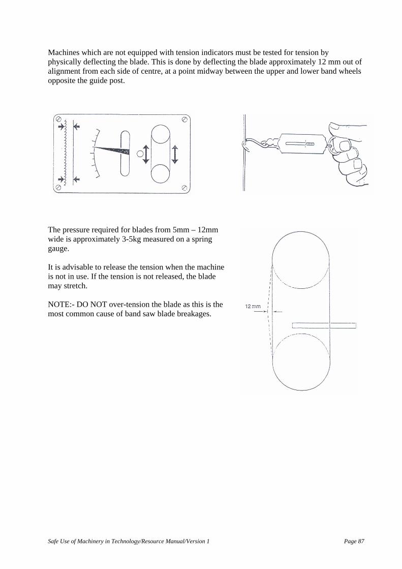
Safe Use of Machinery in Technology/Resource Manual/Version 1 Page 87
Machines which are not equipped with tension indicators must be tested for tension by physically deflecting the blade. This is done by deflecting the blade approximately 12 mm out of alignment from each side of centre, at a point midway between the upper and lower band wheels opposite the guide post.
The pressure required for blades from 5mm – 12mm wide is approximately 3-5kg measured on a spring gauge. It is advisable to release the tension when the machine is not in use. If the tension is not released, the blade may stretch. NOTE:- DO NOT over-tension the blade as this is the most common cause of band saw blade breakages.

Page 88 Safe Use of Machinery in Technology/Resource Manual/Version 1
TRACKING DEVICE A tracking device, which may be either a screw or hand wheel, is positioned at the back or front of the upper band wheel, depending on the design of the particular band saw. This device, when turned, tilts the band wheel on its mounting and in so doing, moves tile blade on the rim. This procedure is known as tracking Tracking Tracking a blade is necessary to ensure the blade runs in a stable position on the band wheel rims and to allow this position to be varied. If the blade is allowed to run in the same position on the rims, it will eventually wear a groove in the tyre. Each time that a blade is installed, it is necessary to check that it tracks correctly on the band wheels. When tracking the blade, the upper wheel is slowly rotated by hand. If the blade moves forward on the upper band wheel, the band wheel may be tilted back slightly by turning the tracking device until the blade tracks in the desired position, and vice-versa if the blade moves backwards.

Safe Use of Machinery in Technology/Resource Manual/Version 1 Page 89
BRAKE This is an optional extra. If it is fitted, it operates by a foot pedal and brakes the lower wheel only.

Page 90 Safe Use of Machinery in Technology/Resource Manual/Version 1
ELECTRICAL SWITCH GEAR
Band saws must be fitted with a flush green ON switch and a red mushroom shaped head STOP switch. Alternatively, a two stage Star Delta rotary start switch, having three positions (OFF, START or RUN) may be fitted. All machines must be fitted with a red ‘mushroom” shaped push EMERGENCY STOP button. This must be of the lock in type ensuring that it is not possible to start the machine until the button is re-set. An isolation switch must be fitted to enable the main power supply to be locked off when maintaining or adjusting the machine. The switches should be placed in an easily accessible position.
Mushroom Stop Switch Rotary Star Delta Switch

Safe Use of Machinery in Technology/Resource Manual/Version 1 Page 91
SAFETY The following safety precautions must be observed when operating, setting up and maintaining a band saw. Pre-Operational Safety Precautions Always isolate the main power to the machine by turning the isolation switch to OFF before carrying out any adjustments. Check that the electricity supply is not on by pressing the machine’s ON/OFF switch. Clean the surrounding work area then ensure that: • the blade has been installed with the teeth facing in the correct direction (ie towards the
operator and with the points facing downwards in the direction of rotation) • the blade has not been damaged and is sharp • the blade type suits the material to be cut the blade is correctly tensioned the table is square
(at 90°) to the blade the blade is tracking correctly • guides are correctly adjusted and not damaged or worn • the thrust wheels are correctly adjusted, spin freely and are not scored • the table insert is in good condition and no off-cuts have been jammed between it and the
blade • the band wheel tyres are clean and not damaged • all guards are correctly positioned and secured • the upper guide post assembly has been adjusted as close as practicable to the top of the
material to be cut • the dust extraction system is free of timber slivers and blocks, and is extracting freely Practical Task Carried out pre-operational checks?
Task Completed Yes No

Page 92 Safe Use of Machinery in Technology/Resource Manual/Version 1
POSITION OF THE BODY When using the Scroll Band saw the operator should position the body to give support to the stock as well as being able to see the line being cut to and guide the stock through the cut. The operator’s hands should be kept well away from the blade and the stock held to ensure they cannot slip into the blade. Machining of Bowed or Cupped Material In most cases material being cut on a band saw has been pre-machined. When cuffing bowed or cupped timber the bowed or rounded side is always placed onto the table. This allows the cut to open up and fall away from the blade as the cut is completed rather than jamming onto the blade as the cut is completed. When cutting with the side fence the bowed or round side is always placed against the fence to ensure a parallel cut to the edge and prevent jamming. Tilted Table The band saw table can be tilted to 45°. To perform any cuts while the table is tilted, a manufacturer’s fence or some form of guide or support can be used to ensure a constant cut parallel to a line or to follow a curve. OPERATIONAL SAFETY PRECAUTIONS The following precautions must be observed to ensure the safe operation of the band saw: • Keep the table of the machine and the surrounding area clean and free of oft- cuts.
• Do not attempt to remove oft-cuts from the table with your hands when the blade is moving.
• Use a push stick whenever possible and keep your hands clear of the blade to prevent injury.
• Do not stand on the right hand side of the band saw. It is the most dangerous position if the blade should break:
• If a blade breaks, turn the machine off immediately and move well clear of the loose blade. When the blade is stationary, use the brake to stop the lower band wheel.
• NEVER attempt to remove the blade or open any guards until both band wheels have stopped revolving.
• Do not place your hands in line with the cut. Keep them at least 50 mm on either side of the blade.
• Do not force feed the cut. Excessive stress on the blade will cause it to break.
• Do not force the blade to cut tighter curves than it is capable of cutting.

Safe Use of Machinery in Technology/Resource Manual/Version 1 Page 93
• Plan the cuts carefully. Make relief cuts (short cuts 90° to the main cutting line) to avoid having to withdraw the material from the blade, particularly when making long or curved cuts.
• If constant, evenly spaced clicks are heard, turn the machine off and inspect the blade for cracks.
• Seek assistance to cut large material, as this will make movement of the material easier.
• Never use a band saw to shorten pre-cut dowels. Cross culling stock can be very dangerous if the workpiece is not held firmly.
• Use the band saw to cut only materials for which it was designed. Never try to cut a piece of string on it for instance.
NOTE! All of the following set-up procedures must be checked by your trainer before the machine is started and he/she must be present when you operate the machine.

Page 94 Safe Use of Machinery in Technology/Resource Manual/Version 1
MACHINE OPERATIONS Ripping The narrow band saw is primarily used for freehand cutting, although it may be used for ripping or making straight cuts using a fence. When straight cutting, the use of a wide blade is recommended as this will follow the line with less deviation than a narrow blade. Some machines have a manufacturer’s ripping fence attached to the table on a guide bar. This may be fitted with a pointer and gauge to enable the fence to be set at the required distance. For greater accuracy, it is advisable to measure the required distance from the fence to the nearest teeth of the blade, before securing the fence. If the machine is not supplied with a ripping fence, a length of straight timber may be cramped onto the table at the required distance from the blade and parallel to it. A high fence should be used when re-sawing. This will allow the material to be held against the fence to produce a square cut of uniform thickness.

Safe Use of Machinery in Technology/Resource Manual/Version 1 Page 95
If several boards are to be cut together, it is advisable to use a wooden comb to help hold the timber against the fence. The comb is made of solid timber and consists of a series of cuts, called fingers, made on the band saw. These flexible fingers bend like springs when material is forced past them and provide a holding force to keep the material against the fence. Procedure for Ripping to a Fence The Pre-Operational Safety Precautions must be observed before attempting this procedure. 1) The main power to the machine must be isolated. The machine’s ON/OFF switch is checked
to ensure the electricity supply is not on. The machine table and the work area surrounding the machine should be clean and free from all off-Cuts.
2) The blade must be correctly selected for the work it will perform it should track correctly and
be tensioned to specifications. The guide assemblies must be adjusted to the recommended specifications.
3) The upper guide assembly is raised to give free access to the blade and the timber straight
edge (fence) is placed on the band saw table to the left of the blade and parallel to it. 4) The specified distance is measured from the inside edge of the fence (the edge nearest the
blade) to the teeth set towards the fence. 5) To ensure that the fence is parallel to the side of the blade, a carpenter’s square is placed
against the front of the table and along the edge nearest the blade. The front of the table may be used in this manner because the blade is always set with its sides at 90 to the front of the table.

Page 96 Safe Use of Machinery in Technology/Resource Manual/Version 1
FENCE IS HELD PARALLEL TO THE BLADE WITH A “G” CRAMP
6) The fence is then secured by placing the foot of a “G cramp at the front and on top of the
fence with the throat of the cramp to the left. When in position, this cramp is tightened with the swivel shoe contacting the flat underside of the table or sitting firmly on a casting web.
7) A second “6” cramp is placed at the back of the fence. The throat of this cramp must face in the same direction as the front cramp. The specified distance should not alter and the edge of the fence should remain parallel with the side of the blade.
8) The upper guide post assembly is lowered as close as practicable to the top of the material to be cut and secured in that position.
9) If a manufacturer’s fence is used, it is moved along the guide bar to the specified distance and locked into position. The distance is measured in the same manner as when using a timber fence. Because this type of fence is being continuously re-located, it is advisable to check that it has remained parallel with the sides of the blade.
10) Before proceeding, check the set up.
11) The material to be cut is placed face down on the table with the straightest edge or bow against the fence. The machine is started and the cut commenced.
12) When ripping wide material, place one hand on top of the material clear of the blade to prevent the material from wandering away from the fence. A push stick should also be used in the other hand once cutting has begun.
13) When ripping narrow material, a push stick should be used at all times to ensure the hands do not come in contact with the blade.
14) When all cuts have been completed, the machine is turned OFF and the band wheels are slowly brought to a stop by lightly applying the brake (if one has been fitted). The machine is isolated, the cramps and the fence are removed and the machine is restored for normal use.
Practical Task Has carried out ripping procedures?
Task Completed Yes No

Safe Use of Machinery in Technology/Resource Manual/Version 1 Page 97
Cutting Angled Blocks or Round Material Angled blocks may be cut by tilting the table to 45°, in most cases they can be cut much easier by using a suitable V°. block jig. It is important that the jig is held securely in position and the material is held down tightly in the jig. Jigs may be made from two angled blocks screwed or nailed to a baseboard. The ideal length of the jig would reach from the front of the table to a point far enough behind the blade to allow it to support the material and be cramped to the table. When ripping round material, a line is drawn through the centre of the material and traced along its length. The blade must follow this line to produce an accurate cut. Procedure for Cutting with a Jig Due to the problems confronted when holding material firmly to cut different shapes on a band saw, it becomes necessary to manufacture and use a jig. The jig enables the material to be firmly held in position and eliminates unsafe procedures which may be attempted when cutting without a jig.

Page 98 Safe Use of Machinery in Technology/Resource Manual/Version 1
The Pre-Operational Safety Precautions must be observed before attempting this procedure. 1) The main power to the machine must be isolated. The machine’s ON/OFF switch is checked
to ensure that the electricity supply is not on. The machine table and the work area surrounding the machine should be clean and free from all off-cuts.
2) The blade must be correctly selected for the work it will perform. It should track correctly
and be tensioned to specifications. The guide assemblies are adjusted to the recommended specifications.
3) The upper guide post assembly is raised to give free access to the blade and the jig to be used
is placed flat on the table. The blade must be located into the slot in the jig and, when located correctly, the jig is pushed forward until the stop on the jig touches the front of the table. It is important that the jig is positioned parallel with the blade. This may be done by using the manufacturer’s fence against one side of the jig or by using a large square placed against the front of the table. When positioned correctly, the jig is cramped in position with “G” cramps. These may be placed at the front or the back of the jig but must be clear of the work area.
4) The material to be cut is placed in the vee of the jig and the upper guide post assembly is
lowered as close as practicable to the top of the material. 5) The power to the machine is restored and the cut is commenced, keeping the hands well clear
of the blade when holding the material. The blade must follow the top corner of the material when cuffing and the material must be held firmly down into the vee of the jig.
6) Before reaching the end of the
cut, a push stick must be used to keep the hands well clear of the blade. The push stick can also aid in the removal of waste material or off-cuts from near the blade while it is revolving. This ensures the well being of the operator’s hands. The waste is removed and placed in the appropriate bin or storage area ready for disposal; care is taken not to throw waste on the floor around the band saw causing a safety hazard.
7) When all cuts have been completed, the machine is turned OFF and the band wheels are
slowly brought to a stop by lightly applying the brake (if one has been fitted). The machine is isolated, the cramps and the fence are removed and the machine is restored for normal use.
Practical Task Has carried out ripping procedures using jig?
Task Completed Yes No

Safe Use of Machinery in Technology/Resource Manual/Version 1 Page 99
Cross Cutting If the table of the band saw has a machined groove to enable a mitre fence to be used, accurate cross cuffing may be achieved by using a fence. Square or angle cutting may be carried out if the mitre fence is set to the required angle. When cross cutting round, square or rectangular timber, a vee block jig, similar to one used for ripping, may be used. If the material to be cut extends more than 50 mm, the waste side should be supported underneath to avoid jamming the blade.
Cutting Curved Shapes Before cuffing curved shapes careful consideration should be given band saw blades available. If a narrow blade is not able to be used for curves, an alternative method must be planned. It may be necessary variety of short or long cuts or to back out after some cuts. Procedure for Cutting Curved Shapes The Pre-Operational Safety Precautions must be observed before attempting this procedure. 1) The main power to the machine must be isolated. The machine’s ON/OFF switch is checked
to ensure that the electricity supply has been disconnected. The machine table and the work area surrounding the machine should be clean and free from all off-cuts.
2) The blade should be correctly selected for the work it will perform. It must track correctly and be tensioned to specifications. The guide assemblies should be adjusted to the recommended specifications.
3) The material to be cut is marked out from the pattern and placed flat on the table with the waste side of the line facing either left or right depending upon the preference of the operator. The upper guide post assembly is lowered as close as practicable to the top of the material.
4) The power to the machine is restored. The method of cutting must be carefully planned and, if relief cuts are necessary, these should be cut first.
5) Where possible, the shortest cuts are made first. It is important to back out carefully from these cuts to prevent the blade grabbing and being pulled off the band wheels.
6) When making long cuts, maintain an even feed rate to achieve accuracy and a good finish. 7) When all the cuts have been completed, the machine is turned OFF and the band wheels are
slowly brought to a stop by lightly applying the brake (if one has been fitted). The machine is isolated and restored for normal use.

Page 100 Safe Use of Machinery in Technology/Resource Manual/Version 1
Procedure for Circle Cutting Using Jig There are several types of jigs which may be used for circle cutting on a band saw. The two most common are the sliding or adjustable pin and the fixed pin types. The following procedure is for the fixed pin type. The Pre-Operational Safety Precautions must be observed before attempting this procedure. 1) The main power to the machine must be isolated. The machine’s ON/OFF switch is checked
to ensure that the electricity supply is not on. The machine table and the work area surrounding the machine should be clean and free from all off-cuts.
2) The blade should be correctly selected for the work it will perform. It must track correctly and be tensioned to specifications. The guide assemblies should be adjusted to the recommended specifications.
3) The upper guide post assembly is raised to give free access to the blade. The jig, or the material to be used as the jig, is placed flat on the table.
The blade must be located into the slot in the jig and this must be in line with the blade. This may be done by using the manufacturer’s fence against the left hand side of the jig or by using a large square placed against the front of the table. If a slot has not been made in the jig, the fence is placed at the required distance to the left of the blade and the material to be used for the jig is placed hard against the fence and pushed forward making the slot. When placed correctly, the jig is cramped in position with “G” cramps. These may be placed at the front, the right hand side or the back of the jig, but must be clear of the work area.
4) A centre line is marked on the jig to the
right of the blade and at 90° to the gullet of the blade. This may be done by using a large square placed against one side of the jig. The required radius is now measured from a tooth set towards the centre line and a pin is fixed in position at this radius and on the centre line. The pin used is generally a nail that has the head cut off. The head may be removed prior to positioning and the nail sharpened both ends or the nail may be fixed in position then the head cut off and the end sharpened.
5) The radius is measured from the centre
line towards the front of the table. A line is marked at this distance parallel with the centre line. This line is called the “setting line”.

Safe Use of Machinery in Technology/Resource Manual/Version 1 Page 101
6) The material to be cut is placed with one edge on the setting line and another edge hard against the blade. The material is then tapped firmly onto the pin in this position. The upper guide assembly is lowered as close as practicable to the material to be cut.
NOTE: If solid timber is to be cut, the end grain should be placed against the blade. This prevents the blade following the grain and producing an irregular shape.
7) The power to the machine is restored.
Using the pin as the centre, the material is revolved in a clockwise direction until the circle is cut. Care must be taken to keep the hands clear of the blade.
8) When all the cuts have been
completed, the machine is turned OFF and the band wheels are slowly brought to a stop by lightly applying the brake (if one has been fitted). The machine is isolated, the cramps and the jig are removed and the machine is restored for normal use.
Practical Task Has cut curved and circular work free hand and using jig?
Task Completed Yes No

Page 102 Safe Use of Machinery in Technology/Resource Manual/Version 1
COMPOUND CUTTING Compound band sawing requires cutting to an outline (pattern) marked on two adjacent sides of a piece of stock. The manufacture of cabriole legs and arms of chairs requires this type of cutting. Marking a Compound Shape The timber to be used for the project must be square on one face and one edge or square dressed all round. The contoured shape or pattern is placed onto one face of the timber with the back flush with the edge. The pattern is held firmly and the shape marked out onto this face. The pattern is then rotated onto the adjacent face of the timber ensuring that the back of the pattern is kept against the shape marked on the previous face. After the shape has been marked out on this face, the project is ready for cutting.
NOTE: The pattern may be used back to back (heel to heel) or face to face (toe to toe). Marking out may be achieved correctly by the use of either method. Procedure for Cutting a Compound Shape The Pre-Operational Safety Precautions must be observed before attempting this procedure. 1) The main power to the machine must be isolated. The machine’s ON/OFF switch is checked
to ensure that the electricity supply is not on. The machine table and the work area surrounding the machine should be clean and free from all off-cuts. Make sure that the table is at right angles to the blade for this procedure.
2) The upper guide post assembly is lowered and secured in a position as close as practicable to
the top of the material to be cut.
3) The power to the machine is restored. The short, straight cuts are made first by sawing on the waste side of the line to a maximum tolerance of +2 mm. The cuts should not be completed but stopped as near to the end as possible (a distance of approximately 2 - 4 mm is recommended). The material is carefully withdrawn (backed out) from the blade. The uncut sections are required to hold the off-cut portions in place as these have been set out for cuffing the adjacent side.
If possible, the uncut portions should be positioned parallel to the grain so that they can be broken off easily, without damage to the finished product, after the second side has been cut.

Safe Use of Machinery in Technology/Resource Manual/Version 1 Page 103
4) When all the lines have been cut on the first side, the material is turned 9Q0 and the lines on the adjacent side are cut. These cuts are completed and the waste discarded.
5) The material is turned back to the first side and the remaining 2 - 4 mm is cut or broken off to
finish the shape. 6) When all the cuts have been completed, the machine is turned OFF and the band wheels are
slowly brought to a stop by lightly applying the brake (if one has been fitted). The machine is isolated, the cramps and the fence are removed and the machine is restored for normal use.
Practical Task Has cut compound curved work?
Task Completed Yes No

Page 104 Safe Use of Machinery in Technology/Resource Manual/Version 1
Basic Static Machine - Panel Saw
Introduction Panel saws are high production machines used to cut large panels into smaller required sizes. MANUALLY FED machines require the operator to set the appropriate fences and stops to the required size and manually feed the stock past the aw to cut the sheet material down to the required finished size.

Safe Use of Machinery in Technology/Resource Manual/Version 1 Page 105
TABLE Panel saws are fitted with a sliding table that enlarges the work table capacity to allow for easier panel handling. The material is loaded onto the table behind the fence which allows larger sheets to be cut and allows easier unloading of the material. The sliding table is supported by a pivoting arm mounted to the body of the machine and to the end of the table.
Rise and Fall Adjustment The saw unit is fully enclosed in the frame and it is raised by means of an external hand wheel generally located at the front of the machine base. The adjustment of the cradle raises and lowers the blade above the table and a locking device holds it at the required height.

Page 106 Safe Use of Machinery in Technology/Resource Manual/Version 1
BLADES Circular saw blades are made from quality steel plate and are perhaps the most highly stressed of all tools when in use. They are made thin in section but large in surface area and are subject to continuous deflection, intermittent shock loading and rapid, unequal changes in temperature. The metal used in their manufacture must be able to hold tension. It must also be able to be brazed for the fitting of hardened tips such as tungsten carbide.
Blade Types The two types of blades used in cross cut saws are: • spring set plate blades (almost obsolete) • tungsten carbide tipped blades (most commonly used) Plate Blades These are blades manufactured from a cast steel plate containing carbon steel alloys. They are ground, tempered, gulleted, tensioned and the teeth are set and sharpened. The blade’s thickness is measured in millimetres and is referred to as the gauge. This may be standard for specific diameters but is generally required by distributors when ordering new blades. Tungsten Carbide Tipped Blades A shaped Tungsten Carbide tip is brazed to the front of each tooth of a high quality plate steel blade. Tungsten carbide tips are very hard, have a longer wearing life and remain sharp longer than spring set plate blades. These blades were originally introduced to solve the tough sawing problems encountered when cuffing abrasive timbers and manufactured boards.

Safe Use of Machinery in Technology/Resource Manual/Version 1 Page 107
RIPPING FENCE The ripping fence is located on the right side of the saw blade, parallel to the blade and at right angles to the cross slide. It slides on a guide bar which is attached to the front of the table and its function is to guide the material during the cuffing process, to achieve a straight cut. The fence is adjusted sideways at right angles to the front of the table to the right of the saw blade and may be fixed securely at the desired position by rapid eccentric clamps activated by a single lever. Moving it down locks it and up unlocks it. When large panels or boards are to be cut and the whole table is utilised, the rip fence must be removed. On most machines the fence is swung under the table without dismantling. The fence in this position is out of the way and cannot be damaged.
Stops Stops are positioned along the squaring off fence to allow accurate and constant cuts to be squared from the stop. The stops may be swung back out of the way when not in use. The reference stops allow direct reading of the measurements set along the entire length of the panel.

Page 108 Safe Use of Machinery in Technology/Resource Manual/Version 1
Angle Fences - cut off fences These are small mountable fences which fit onto the cross cut table. They come in various designs from adjustable angle to a fixed mitre fence.
GUARDS Designed to cover the saw blade to ensure the safety of the operator from kickback. There are basically three types of guards:
Movable crown guard - fixed to riving knife Crown guard - fixed to riving knife Suspended crown guard
Movable Crown Guard This is a movable guard, fixed to the riving knife. The guard covers the blade until activated by the movement of the material. It is designed to rise as the material moves underneath at the beginning of the operation and to return to its original position on completion of the operation.

Safe Use of Machinery in Technology/Resource Manual/Version 1 Page 109
Crown Guard
A crown guard that is not self-adjusting can also be fixed to the riving knife. This guard is fixed in a permanent position above the blade, for height adjustment it relies on the saw blade itself being raised or lowered.
Suspend Crown Guard
Some consider the suspended crown guard to be the safest, as it remains in place on the machine, it does not obstruct blade retraction or replacement. If fitted with a dust extractor, it keeps the machining table cleaner and reduces the amount of sawdust in the working environment.

Page 110 Safe Use of Machinery in Technology/Resource Manual/Version 1
ELECTRICAL SWITCHES Control panels come in various shapes and forms, the main criteria for the switches are that the ON switch is green in colour and with the control panel face. The OFF switch should be red in colour and be of a mushroom shape standing out from the control panel face.
Control Switches On modern machines the control panel may contain switches to control the following six functions:
1. To raise and lower the motor for changing speeds.
2. To display read outs for motor speed.
3. To tilt and lift the blade using electro mechanical systems.
4. Starting scribing saws and for left/right adjustment of the scribing saw.
5. Starting the main saw.
6. ALL machines must be fitted with a large red emergency stop button. This must be of the push-in type to ensure that it is not possible to start the machine until the button has been re-set.
An isolation switch must be fitted to enable the main power supply to be turned off when maintaining or adjusting the machine. The switches should be placed in an easily accessible position

Safe Use of Machinery in Technology/Resource Manual/Version 1 Page 111
RIVING KNIFE Hand fed circular saws must be equipped with a spreader known as a riving knife or splitter. This is made from tempered steel, or similar material, and must be the same thickness as the cut (kerf) made by the saw blade. The edge of the riving knife closest to the blade must be shaped to a radius that is not greater than that of the largest diameter blade used in the machine. It must be able to be adjusted vertically and horizontally to suit different blade diameters. It is fitted below the machine table, behind and in line with the saw blade and on the same rise and fall adjustment as the blade. This allows the same height to be maintained as the blade is adjusted up and down. On machines where the guard is not mounted on the riving knife, the top of the riving knife should be set just below the top of the saw blade to allow for grooving operations. The function of the riving knife is to:
• prevent material from closing in (binding) on the rear of the blade after cuffing causing kickback
• act as a guard to the back of the saw blade
The maximum gap between the blade and the riving knife should not exceed 13 mm, 10 mm is close to best practise.
BRAKE Most modem machines have an electrically interlocked foot brake to stop the saw blade when the machine has been turned off. This promotes safety and convenience, as the machine can be left rather than waiting for the blade to stop revolving.

Page 112 Safe Use of Machinery in Technology/Resource Manual/Version 1
MANUALLY OPERATED PANEL SAW Pre Operational Safety Precautions ISOLATE the machine and check that the electricity supply has been isolated by pressing the machine’s ON/OFF switch. Then ENSURE that: • A push stick is provided to be used whenever possible to keep your hands clear of the blade • all guards are correctly positioned and secured • if a crown guard with an extension piece is fitted, the extension piece is positioned as close as
practicable to the material being cut • the riving knife is positioned correctly the blade is installed with the teeth facing in the correct direction, e towards the operator, with
the points facing down • the blade is not damaged and is sharp • the blade is square (90°) to the table • the table is free of grit or other foreign material • the fence is square to the table and locked in position • the work area is clear of off-cuts and all components are stacked appropriately in the correct
area and on pallets After all practicable steps have been taken to eliminate noise and vibration on a machine, the use of a modern, noise reducing blade may be the best solution. NOTE! NEVER USE THE RIPPING FENCE AS A STOP TO CUT NARROW MATERIAL. IT MAY RESULT IN A KICKBACK. Manual Operation Panels are generally cut to width first on this machine then turned 90° and rested against a squaring fence to be cut to length. The largest width of panel these machines will cut, varies with the machine’s design. The table on the left-hand side of the machines moves past the saw blade (similar to that of a dimension saw bench). The main application for the sliding table panel saw is the clean cutting of panels and boards, by utilising the roller carriage and cross slide, board material can be cut to size on all four sides.

Safe Use of Machinery in Technology/Resource Manual/Version 1 Page 113
Personal and Operational Safety Operational Safety Safety can be promoted with the use of protective clothing and footwear and by the way the various operations are performed on the machine. To further promote personal safety, the operator should:
• Remove rings, watches, bracelets • Button up or roll up shirt sleeves • Remove ties • Keep long hair tied back • Wear safety shoes • Wear safety glasses and hearing protection
To promote the safe use of machinery, the operator should:
• Be sure all moving parts are clear of any obstructions before starting • Make sure a push stick is available to push small material past the saw • Do not cut material that is too large for the machine • Keep hands away from moving parts • Use correct procedures and work practises • Make sure that protection screens are correctly placed to restrict access to work areas
Operator Safety To ensure the safety of the operator, he/she must be aware of the safe use of the panel saw by ensuring the correct use of the following points:
• Guards • Large panel handling/loading • Operator position • Feed speed • Push stick • Housekeeping

Page 114 Safe Use of Machinery in Technology/Resource Manual/Version 1
Guards All guards which cover the motor and drive belts should be closed and locked while the machine is in operation. The crown guard fixing method has three variations:
• fixed securely to the riving knife • fixed to the crown guard but adjustable • suspended crown guard
Whichever method is used to secure the crown guard, all adjustments to the guard must be made before the saw is turned on. It should not be more than 13 mm above the surface of the stock being cut.
Large Panel Handling/Loading Large panels require the use of a forklift or several people to load the panels onto the sliding table. The operator should ensure that he does not strain his/her back while loading or unloading the machine. During the cutting operation, normally the stock is ripped to the required width first - always use a person to tail out the stock being ripped. The ripped panel should be stacked on a pallet truck and any off-cuts disposed of to ensure that they do not become a hazard on the factory floor. Operator Position The operator should NOT stand in line with the saw blade. He/She should position themselves behind the sliding table to allow the stock to be pushed through at a constant feed rate. This position should allow the use of the adjustable return bar to return the sliding table to a non cutting position.
Feed Speed The rate of feed will be determined by the thickness of stock or the number of panels stacked on top of one another. The rate of feed speed should be a constant even rate. If the job requires the operator to force the cut, the sharpness of the blade should be checked. A blunt blade will leave burn marks along the cut.

Safe Use of Machinery in Technology/Resource Manual/Version 1 Page 115
Push Stick When ripping narrow stock, a push stick is used to pass the stock between the blade and the fence. This ensures the operator’s hand does not come too close to the saw blade.
Adjusting the angle of the saw The saw blade can be tilted over to an angle of 45° by using the angle adjustment wheel on either the left or right hand side of the machine. To change the angle, the angle adjustment lock is released and the angle adjustment wheel is turned until the required angle is gained; the angle indicator on the front of the machine will show the angle the saw blade is set at. The angle adjustment lock should always be tightened. A trial piece of stock is cut and tested to check the angle of the cut and adjusted if necessary. To stop breakout on the back of the sheet, ensure the scribing saw is raised above the surface of the table to scribe the stock 2 mm deep.
Push Stick
Scribing Saw

Page 116 Safe Use of Machinery in Technology/Resource Manual/Version 1
Housekeeping All stock should be stacked on pallets or in the required position, ready for transport to the next manufacturing process. Off-cuts not required should be stacked or placed in the appropriate bin or area ready for disposal. Spills of oils, chemicals etc should be roped off and soaked up with sawdust then removed and the area cleaned up. The machine should be cleaned and any off-cuts removed at regular intervals. Maintaining good housekeeping helps to reduce the risk of accidents and machine breakdowns. OPERATIONAL SAFETY PRECAUTIONS When operating a panel saw:
• keep the table of the machine and the surrounding area clean and free of off-cuts • never attempt to remove off-cuts from the table with your hands when the saw is
running • never place your hands in line with the cut • never stand directly behind the material being cut • ensure scribing saw is set correctly • ensure that the crown guard is set in the correct position • do not force feed the cut • if ripping or cross-cuffing bowed material, place the round face down onto the table
and the round edge against the fence • seek assistance to cut long, heavy or large material • never use the ripping fence as a stop to dock narrow material. Always use the stops on
the squaring fence. Considerations when Ripping There are a variety of materials that may be straight ripped on the panel saw. Some common materials that may be cut are:
• Plywood - plain - veneered • MDF - plain - veneered • Particle board - plain - veneered
Plywood A manufactured board ranging in thickness from 3 - 25 mm is commonly used. It can be bought as a plain veneered plywood or have a fancy veneer face. MDF (Medium Density Fibreboard) A manufactured board ranging in thickness from 3 - 32 mm is commonly used. It can be bought as a plain sheet of MDF or veneered on both surfaces. Particle board A manufactured board ranging in thickness from 6 - 32 mm is commonly used. It can be bought as a plain sheet or veneered on both surfaces.

Safe Use of Machinery in Technology/Resource Manual/Version 1 Page 117
Process of Cutting Material 1) To ensure ease of operation when breaking down sheets into panel components, one edge of
the sheet is trimmed for straightness and squareness and all ripping and squaring completed off this edge.
2) The width of material should be set so that the distance between the saw blade and ripping
fence is the required dimension. 3) When ripping, always have the face side of the sheet facing upwards, because breakout will
occur underneath unless the scribing saw is used in line with the saw blade and raised above the height of the table
4) The required length is then cut by setting up the stop to the required length on the fence of
the sliding table. 5) The material is squared off to the required length - ensure panels are cut with face up. In some cases such as plain stock, a multiple number of sheets may be cut at one time - with this method there may be some breakout on the back of the sheets. The panel saw can be used to square solid timber to length. For best results, the timber should be placed in front of the fence, on the same side as the saw blade. lf the timber is positioned behind the fence it should be held firmly, otherwise the blade will push the material away from the fence and the cut will not be square.

Page 118 Safe Use of Machinery in Technology/Resource Manual/Version 1
Basic Static Machine - Vertical Drill Press
INTRODUCTION Vertical drills are used to accurately and safely drill holes in timber, metal and plastics. Drills are available in varying pedestal lengths to suit floor or bench mounting. Powered by an electric motor and driven by pulleys and belts a variety of speeds can be chosen. Combining a graduated feed, depth stop and fences or vices accurate repetitive boring is possible.

Safe Use of Machinery in Technology/Resource Manual/Version 1 Page 119

Page 120 Safe Use of Machinery in Technology/Resource Manual/Version 1
TABLE A machined surface to support work that can be raised, rotated or lowered and locked in position. Centre opening allows the drill bit to pass through the table. Slots in the table allow for the fitting of a vice. Table Rise and Fall Wheel Allows the raising and lowering of the table to suit a variety of material sizes. Table Locking It is possible for a vertical drill to have two table locking points. One lock clamps the table to the column. This lock allows the table height to be changed by using the Riske and Fall Wheel. It also allows the table to pivot horizontally. The second, if present, allows the table to be tilted for angle drilling or rotated 90° for end grain drilling. BELT and PULLEY Used to vary the speed of the chuck to suit hardness of materials and size of hole being bored. The motor is unlocked and brought forward, allowing the “V’ belt to be changed on the pulleys.

Safe Use of Machinery in Technology/Resource Manual/Version 1 Page 121
DEPTH GAUGE A stop set on the travel arm once set, stops any further movement. Used to bore to a pre-set depth. Allows accurate repetitive boring. SWITCH The drill must be fitted with a flush green ON switch and a raised red STOP switch. An isolation switch must be fitted to lock off main power supply when maintaining or adjusting the machine. The switches should be placed in an easily accessible position.

Page 122 Safe Use of Machinery in Technology/Resource Manual/Version 1
SAFETY Safe Practice When Using a Vertical Drill 1) Before operating the drill, secure all items of loose clothing and hair. Personal safety
equipment such as safety glasses and approved footwear must be worn.
2) Isolate power to avoid accidental starting when changing bits, making major adjustments, fitting or removing fences and stops or when performing maintenance operations.
3) Ensure that the Vertical Drill Press and the work area around it is clear of any obstruction.
4) Select the correct drill bit for the materials to be bored. Make sure that shank of the drill bit is free of burrs and that the drill bit is correctly sharpened.
5) Insert the drill bit into the chuck and tighten the three (3) jaws uniformly with the correct size chuck key.
6) Be sure to remove the chuck key from the chuck before starting the machine. Removing the drill bit at the completion of the work.
7) Adjust the table heights to suit the material being bored.
8) Adjust the depth stop if necessary.
9) Never attempt to drill any work unless it lies flat on the table.
10) Any work which will not sit flat on the table must be supported in a jig, held in a vice or clamped to the table.
11) Request assistance in supporting long lengths of material.
12) When drilling sheet metal special care must be taken when the drill bit is breaking through the material surface.
13) Take notice of the position of the stop switch in case of emergency, THEN START THE MACHINE.
14) During drilling allow the drill bit to cut at its own speed without applying undue force.
15) If a drill bit clogs, do not attempt to clear it whilst it is in motion.
16) Do not clear the work table of waste material while the machine is in operation.
17) DO NOT GET DISTRACTED.
The operation of this machine requires the operator’s undivided attention and concentration at all times. NOTE: ALL THE ABOVE POINTS ARE OF EQUAL IMPORTANCE

Safe Use of Machinery in Technology/Resource Manual/Version 1 Page 123
CHANGING DRILL SPEED Vertical Drill Vertical drills use stepped pulleys to alter the rotation speed of the bit. A vertical drill may have two or three stepped pulleys. This is due to accommodate different materials and different bit sizes. A drill with three pulleys offers a wider range of speeds to choose from. A two pulley drill usually has five speeds and three pulley can have a choice of nine speeds. The required rotation speed is chosen by moving a V belt up or down on the pulleys. To obtain the slowest rotation speed use the smallest pulley on the motor and the largest pulley on the spindle. Changing Speeds 1) Ensure the power is isolated before commencing any speed adjustment.
2) Open the belt guard.
3) Unlock the belt tension knob, this usually allows the motor to move toward the spindle.
4) Shift the belts to obtain the required rotation speed. It is important to ensure the belts are running in line with the pulleys.
5) Move the motor away from the spindle to obtain the desired belt tension and lock the belt tension knob.
6) Close the belt guard.
7) Re instate the power supply.
8) Test drill on scrap material for correct rotation speed and correct belt tension. If the speed is incorrect or if the belts are slipping, repeat the above procedure.
Changing a Drill Bit Most drills have a standard three-jaw, key tightened chuck. If frequent changing of bits is necessary, a keyless chuck is the best type to use. This type is tightened by hand and requires a flick of the wrist to undo.
Three Jaw Chuck Keyless Chuck