safepace 450 radar sign installation manual.… · 1-800-236-0112 5100 west brown deer road brown...
TRANSCRIPT

1-800-236-0112www.tapconet.com
5100 West Brown Deer RoadBrown Deer, WI 53223
Distributed by
Traffic Logix® SafePace® 450 Radar Sign
Installation Manual Version 1.4

1-800-236-0112www.tapconet.com
5100 West Brown Deer RoadBrown Deer, WI 53223
Distributed byPage 2
Table of Contents Overview ....................................................................................................................................................... 3
Available Power options ............................................................................................................................... 3
Sign Portability and add-ons ......................................................................................................................... 3
Site Selection ................................................................................................................................................. 4
Positioning the Sign....................................................................................................................................... 5
Installation .................................................................................................................................................... 6
Mounting the Sign ......................................................................................................................................... 6
Standard Pole Banding Mounting (hardware included) ........................................................................... 6
Universal Mounting Bracket System (Optional) ....................................................................................... 7
Installing the Mounting Brackets .......................................................................................................... 7
Mounting and Dismounting the Sign ............................................................................................................ 9
Powering the Sign ....................................................................................................................................... 10
AC Power ................................................................................................................................................. 10
Battery Power ......................................................................................................................................... 10
Installing the battery ........................................................................................................................... 12
Solar Power ............................................................................................................................................. 13
Mounting the Solar Panel ................................................................................................................... 13
Wiring the Solar Panel to the Sign ...................................................................................................... 14
Turning the Sign On and Off ....................................................................................................................... 15
Operating your sign ..................................................................................................................................... 16
Maintaining your sign ................................................................................................................................. 16
Replacing key internal sign components ................................................................................................ 16
Warranty ..................................................................................................................................................... 17
Technical Support ....................................................................................................................................... 18

1-800-236-0112www.tapconet.com
5100 West Brown Deer RoadBrown Deer, WI 53223
Distributed byPage 3
Overview The SafePace® 450 speed display sign offers a portable speed solution that doesn't compromise on digit
size or visibility. The innovative sign displays vehicle speed in full 15" LED digits at a weight of only
around 20 lbs (depending on options) and can be seen from up to 1200 feet away. Using optional
battery power, the sign can function autonomously for up to two weeks. With a full range of features
including user-friendly software, low power consumption, vandal resistance, and universal mounting
brackets, the SafePace® 450 is the lightweight sign with full size impact.
Available Power options The SafePace® 450 radar sign is energy efficient. The ultra-low power sign utilizes the most power-efficient
radar technology available. It comes with the following power options:
SafePace® 450 AC Powered
SafePace® 450 4 Cell Battery (4 Cell Lithium Battery – Up to 2 week operation between charges)
SafePace® 450 Solar Powered (backup battery is 4 cell Lithium battery above)
*Note – warranty on the battery is limited for 1 year – please call Technical Support for more details.
Sign Portability and add-ons The SafePace® 450 radar sign is a very lightweight sign. When used in conjunction with the optional
Universal Mounting Bracket, it is quite portable. At just around 22 lbs, the lightweight sign is quick and
simple to transport and can be mounted in minutes.
Compact or full size face Choose compact 4" or full size 6" Your Speed text, both of which include full size 15” digit speed display.
Face plate Dimensions
Compact size face 28.0” (h) x 26.0” (w)
Full size face 40.0” (h) x 30.0” (w)

1-800-236-0112www.tapconet.com
5100 West Brown Deer RoadBrown Deer, WI 53223
Distributed byPage 4
Portable Speed Control option The SafePace® 450 radar sign can also be mounted to the SafePace® Cruiser LT.
Figure 1, SafePace Cruiser LT
Complementary add-on options External components can also be attached like beacons for a complete school zone system, or a ‘SLOW
DOWN’ sign.
Figure 2, Complete School Zone System Figure 3, ‘SLOW DOWN’ sign
For more information on the above options, please contact your Sales representative or call Technical
Support. You can also visit the documentation section in the customer downloads area of our Traffic
Logix® website for more information.
Site Selection Site selection varies with the application in which the SafePace® 450 radar sign is being used. The following guidelines, however, should generally be adhered to:
i) Choose a position where the line of sight from the radar sign to the vehicle will beuninterrupted. Consideration should be given to how the location may develop with time.The following types of questions should be considered: Will any trees grow directly in theline of vision? Is it likely that road traffic signs will be erected in a position that couldobstruct the field of view?
ii) The radar sign should be installed directly adjacent to the lane of cars it is targeting since aninterfering lane of traffic may cause inaccurate speed readings.
iii) The structure that the radar sign is mounted to should be stable and firm. Avoid structuresthat are likely to be affected by wind or rain. The suggested pole type for installation is

1-800-236-0112www.tapconet.com
5100 West Brown Deer RoadBrown Deer, WI 53223
Distributed byPage 5
either a 4 inch diameter circular metallic pole or a 4 x 4 inch wooden pole is an ideal choice. If a ‘Telespar’ pole is used, it is strongly advised that a 2 inch pole be used.
Positioning the Sign
Similar to other road signs, the SafePace® 450 radar sign should be installed near the closest lane of traffic, although off the actual road. The recommended height of the lower edge of the radar speed sign is approximately 7 feet above the surface of the road. The display should be turned towards oncoming traffic so that it is clearly visible to approaching drivers.
Figure 4, symbolic location
Figure 5, zone of detection
Range of
Detection up to
1200 ft.
1-800-236-0112www.tapconet.com
5100 West Brown Deer RoadBrown Deer, WI 53223
Distributed byPage 6
Installation There are several methods/hardware options available for the installation of the sign. The SafePace®
450 radar sign can be installed as a full size or compact size sign, and optionally mounted with a
universal sign bracket or pole bracket.
Mounting the Sign There are several methods and hardware options available to install the sign.
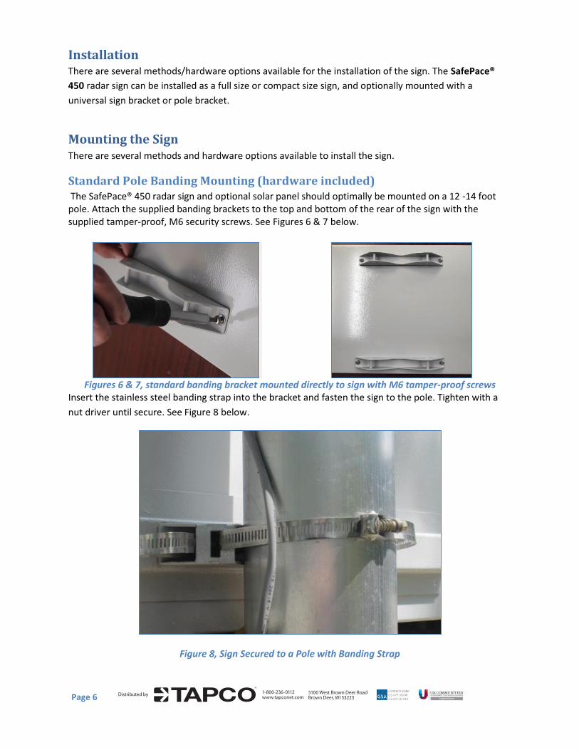
Standard Pole Banding Mounting (hardware included) The SafePace® 450 radar sign and optional solar panel should optimally be mounted on a 12 -14 foot pole. Attach the supplied banding brackets to the top and bottom of the rear of the sign with the supplied tamper-proof, M6 security screws. See Figures 6 & 7 below.
Figures 6 & 7, standard banding bracket mounted directly to sign with M6 tamper-proof screws Insert the stainless steel banding strap into the bracket and fasten the sign to the pole. Tighten with a
nut driver until secure. See Figure 8 below.
Figure 8, Sign Secured to a Pole with Banding Strap

1-800-236-0112www.tapconet.com
5100 West Brown Deer RoadBrown Deer, WI 53223
Distributed byPage 7
Universal Mounting Bracket System (Optional) The SafePace® 450 radar sign comes with an optional Universal Mounting Bracket that allows the sign to
be easily mounted to virtually any type of pole or surface in a quick, easy and secure manner.
The SafePace® 450 mounts to the bracket and is just as easily removed from the bracket with just the
turn of a key.
The quick mount and dismount feature of this bracket readily allows the sign to be moved from one
location to another with relative ease and convenience.
Installing the Mounting Brackets
Sign Bracket
Attach the Sign Bracket to the backside of the sign using the included hardware.
Figure 9, Use supplied hardware Figure 10, Backside of Sign bracket
Pole Bracket
The Pole Bracket can be secured to any type of standard pole or Telespar type pole by a choice of
banding straps, lag screws, or bolts and nuts.
Figure 11, Pole Bracket mounted to circular pole Figure 12, Pole Bracket mounted to
2” Telespar pole

1-800-236-0112www.tapconet.com
5100 West Brown Deer RoadBrown Deer, WI 53223
Distributed byPage 8
Installation of Pole Bracket on Telespar Pole
Use the supplied 2.5” stainless steel security bolts and nuts to secure the Pole Bracket to the 2” Telespar
pole.
*A 2 inch Telespar pole should be usedIt is very important that the head of the bolt be placed on the Telespar pole (See Figures 13
and 14) and that the nuts be placed on the inside part of the bracket (see Figures 15 and 16).
Figure 13 Figure 14 Figure 15 Figure 16
Installation of the Pole Bracket using supplied banding straps
It is highly recommended that if banding is used to secure the Pole Bracket additional screws and/or
bolts should also be used (see Figure 18 below) to further prevent theft and vandalism.
Figure 20
Figure 18, Additional lag bolts
should be used for added security
Figure 17, Pole bracket
banded to utility pole
Figure 19, Profile view
of pole bracket
banded
Banding strap
holes (4)
Teleapar pole
mounting holes (6) U-Channel
mounting holes (4)
POLE BRACKET
1-800-236-0112www.tapconet.com
5100 West Brown Deer RoadBrown Deer, WI 53223
Distributed byPage 9
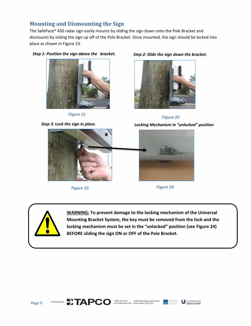
WARNING: To prevent damage to the locking mechanism of the Universal
Mounting Bracket System, the key must be removed from the lock and the
locking mechanism must be set in the “unlocked” position (see Figure 24)
BEFORE sliding the sign ON or OFF of the Pole Bracket.
Mounting and Dismounting the Sign The SafePace® 450 radar sign easily mounts by sliding the sign down onto the Pole Bracket and
dismounts by sliding the sign up off of the Pole Bracket. Once mounted, the sign should be locked into
place as shown in Figure 23.
Locking Mechanism in “unlocked” position
Figure 21 Figure 22
Step 3: Lock the sign in place.
Step 1: Position the sign above the bracket. Step 2: Slide the sign down the bracket.
Figure 23 Figure 24

1-800-236-0112www.tapconet.com
5100 West Brown Deer RoadBrown Deer, WI 53223
Distributed byPage 10
Powering the Sign The SafePace® 450 radar sign is offered in several powering models. Depending on what model you have
purchased, powering the sign will vary.
AC Power
WARNING: ELECTRICAL SHOCK HAZARD To avoid serious injury or even death,
all electrical wiring should be performed by a qualified and professional
electrician in accordance with local electrical codes. Mishandling of electrical
wiring may also result in damage to the unit and may void product warranty.
The SafePace® 450 radar sign is equipped to accept 100-240 volts of AC power. For these signs (standard model), the regulated power supply comes already prewired, and your sign is ready to operate once it is mounted and wired to the incoming power supply. The Line (BLACK) and Neutral (WHITE) wires of the incoming power supply should be connected to the marked terminals. The Ground wire should be connected to the GREEN/YELLOW terminal (see Figure 26 below).
Figure 25, AC power supply terminal block Figure 26, close-up view
Battery Power Signs that are powered by a Lithium battery come with a 4 Cell 15 Ah battery. In most instances, the battery will be shipped already installed in the sign. At times, though, due to some shipping restrictions on Lithium batteries, the battery may be shipped separately. Once the battery is received, remove the battery from the shipping packaging.
WARNING: the Lithium battery comes with a protective black wrap on the outside of the unit that SHOULD NEVER be removed; doing so will damage the battery and will create a potential hazard. The Lithium batteries supplied with the SafePace® 450 radar sign are stable and safe when handled and used properly. Care should be taken not to bend the battery or puncture it with sharp objects as fire and/or explosion may result.
1-800-236-0112www.tapconet.com
5100 West Brown Deer RoadBrown Deer, WI 53223
Distributed byPage 11
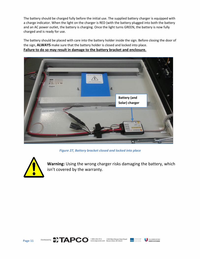
The battery should be charged fully before the initial use. The supplied battery charger is equipped with a charge indicator. When the light on the charger is RED (with the battery plugged into both the battery and an AC power outlet, the battery is charging. Once the light turns GREEN, the battery is now fully charged and is ready for use.
The battery should be placed with care into the battery holder inside the sign. Before closing the door of
the sign, ALWAYS make sure that the battery holder is closed and locked into place. Failure to do so may result in damage to the battery bracket and enclosure.
Figure 27, Battery bracket closed and locked into place
Warning: Using the wrong charger risks damaging the battery, which isn’t covered by the warranty.
Battery (and
Solar) charger

1-800-236-0112www.tapconet.com
5100 West Brown Deer RoadBrown Deer, WI 53223
Distributed byPage 12
Installing the battery
To install the battery in the battery bracket, pull on the plunger pins on either end of the upper bracket (see Figure 28 below) and flip open the bracket door.
Figure 28, Battery bracket door flipped open
Gently insert the battery into the lower bracket and lay it flat against the enclosure. Next, gently close the battery bracket door and make sure the plunger pins lock into place.
Figure 29, Battery inserted and connected
Once the battery is secured in the battery bracket, feed it’s connector through the adjacent space in the lower bracket, then connect the battery and sign power connectors. Once connected, the sign will power on.

1-800-236-0112www.tapconet.com
5100 West Brown Deer RoadBrown Deer, WI 53223
Distributed byPage 13
Solar Power The SafePace® 450 Solar Power radar sign model comes standard with a small solar panel and mounting, a 4 Cell Lithium Ion battery, and a solar charger. The solar panel is quick to install and should suffice in most installations.
Figure 30, solar panel
Mounting the Solar Panel
The solar panel should be mounted at the highest point on the pole, optimally 10-12 Feet high. Mount the panel using the supplied solar panel bracket (see Figure 31 below) and please follow the instructions provided by the manufacturer which are supplied in the bracket’s packaging.
Figure 31, solar panel mounting bracket
The two-part bracket allows for full adjustment in order to best position the panel towards the sun. It is optimal to position your solar panel towards due Solar South (not magnetic South), if you are in the northern hemisphere and towards due Solar North (not magnetic North) if you are in the southern hemisphere.
Regardless of whether you are in the northern or southern hemisphere, Solar North/South is the position of the sun in the sky at exactly the midpoint between sunrise and sunset.

1-800-236-0112www.tapconet.com
5100 West Brown Deer RoadBrown Deer, WI 53223
Distributed byPage 14
The solar panel should be angled 15 degrees above the latitude of the installation site which you can readily ascertain from mapping software or for free from mapping and travel direction websites on the internet.
For example, if the latitude of the installation site is 45 degrees then the solar panel should be installed at an angle of 60 degrees, as shown in Figure 32.
Wiring the Solar Panel to the Sign
As shown in the following images, the solar panel and the sign come pre-wired with quick connectors to allow for a simple installation. Each of the cables from the sign can only be connected to the corresponding connector on the solar panel.
Figure 33, Panel connectors Figure 34, Sign connectors
Insert the connectors from the sign into the corresponding connectors from the solar panel as shown
below (Figure 35).
Figure 35, Connectors partially inserted
Slide the connectors together until you hear a click and you can no longer slide them apart easily. Once connected the cables should look like the following:
Figure 32

1-800-236-0112www.tapconet.com
5100 West Brown Deer RoadBrown Deer, WI 53223
Distributed byPage 15
Figure 36, Sign and Panel cables connected
Next, open the sign and connect the battery connector to either of the solar charger connectors.
Figure 37
WARNING: Before ever doing any maintenance on a sign, it is critical that the power
is first turned off. This will prevent accidental electrical shock that can be fatal and
that can also damage electrical components.
Turning the Sign On and Off The SafePace® 450 radar sign will immediately power on once the power source is connected. There is
no ON/OFF switch supplied with the sign. To turn the sign off, simply disconnect the battery on the
battery models and the connector on the AC and Solar models.
Solar charger
connectors
To prevent damage to the solar charger, connect the
solar panel to the sign BEFORE connecting the battery
connectors to the solar charger in the sign.
Battery
connector

1-800-236-0112www.tapconet.com
5100 West Brown Deer RoadBrown Deer, WI 53223
Distributed byPage 16
Operating your sign Once mounted and powered, your sign can be connected to using Bluetooth or Wi-Fi, and easily programmed and managed or scheduled with our easy to use software.
For more information on operating and programming your sign, please refer to the SafePace® Pro User Manual. *Get the latest version at: http://trafficlogix.com/customerarea/customerdownloads
Maintaining your sign
Replacing key internal sign components The SafePace® 450 radar speed sign are comprised of the following key electronic components (and
respective quantities):
• Controller Card (1)
• Radar Head with controller (1)
• Speed Violator Strobe PCB (2)
• Ambient Light Sensors (2)
WARNING: Before ever doing any maintenance on a sign, it is critical that the
power is first turned off. This will prevent accidental electrical shock that can be
fatal and that can also damage electrical components.
If you suspect that you require a replacement of any of the above-mentioned components, please call
Technical Support. If necessary, a Diagnostic Toolbox can be sent out to help trouble-shoot any issues
you may be having.

1-800-236-0112www.tapconet.com
5100 West Brown Deer RoadBrown Deer, WI 53223
Distributed byPage 17
Warranty
Subject to the following conditions, Traffic Logix Corporation (“Traffic Logix”) warrants that the
SafePace® 450 Speed sign (the “Product”) is free from defects in materials and workmanship. This
limited warranty begins on the invoice date of your purchase of the Product and extends:
For TWO (2) calendar years on the radar sign, and
For ONE (1) calendar year on the batteries.
This limited warranty extends only to the original purchaser of the Product when purchased either
directly through Traffic Logix or through an authorized Traffic Logix distributor and is not assignable or
transferable to any subsequent purchaser or end-user. Traffic Logix’s obligation and liability under this
warranty are expressly limited to repairing or replacing, at Traffic Logix’s option, defective products. In
no circumstances shall Traffic Logix’s liability, whether in contract or tort, under any warranty, in
negligence, or otherwise, exceed the amount of the purchase price of the product. Traffic Logix shall not
be liable for special, indirect, or consequential damages of any kind. This warranty does not cover
damages resulting from normal wear and tear, incorrect installation or operation, use other than for the
product’s intended purposes, vandalism, and extraordinary environmental circumstances. Traffic Logix
reserves the right to charge for these damages to the product at rates normally charged for repairing
such products not covered under this warranty. Damages resulting from any physical changes or
alterations made to the product other than Traffic Logix will render this warranty VOID. Using any parts
or accessories not supplied or approved by Traffic Logix, such as battery chargers, will further render the
warranty VOID.
Traffic Logix neither assumes, nor authorizes any person to assume for it, any other liability in
connection with the sale of the Product, and there are no agreements or warranties collateral to or
affecting this limited warranty. THE LIMITED WARRANTY SET FORTH IN THIS AGREEMENT IS THE
EXCLUSIVE AND SOLE WARRANTY APPLICABLE TO THIS PURCHASE. ALL OTHER WARRANTIES, EXPRESS
OR IMPLIED, INCLUDING, BUT NOT LIMITED TO THE IMPLIED WARRANTY OF MERCHANTABILITY AND
THE IMPLIED WARRANTY OF FITNESS FOR A PARTICULAR PURPOSE ARE EXPRESSLY DISCLAIMED.
Traffic Logix does not warrant that any of its products will meet or comply with the requirements of any
applicable federal, state or local safety code, law, regulation or ordinance (“Applicable Safety Laws”).
Buyer acknowledges that Traffic Logix’s products are to be used only in accordance with the attached
Conditional Terms of Use and any Applicable Safety Laws. Buyer agrees that there shall be no coverage

1-800-236-0112www.tapconet.com
5100 West Brown Deer RoadBrown Deer, WI 53223
Distributed byPage 18
or benefits of any kind under this limited warranty if it is determined by Traffic Logix that the Product
was not installed or used in accordance with the Conditional Terms of Use or Applicable Safety Laws, or
if the Product has been altered in any way by anyone other than Traffic Logix, or if the Product has been
subject to any misuse or accident. In addition, Buyer assumes and agrees to indemnify Traffic Logix for
all risk, liability or expense that results from any installation or use of the Product that is not in
accordance with the Conditional Terms of Use or any Applicable Safety Laws.
Warranty Replacement Procedure
In order to submit a claim for the repair or replacement of the Product under this limited warranty, you
must do the following:
1) Obtain a Return Materials Authorization number by contacting Customer Support. Do not ship your
defective product to Traffic Logix prior to contacting Customer Support.
2) A Customer Support agent will evaluate the Product to determine if it is defective. If the product is
defective, then you will need to submit your contact information, and proof of purchase (including the
date or purchase), in order to obtain repair or replacement parts.
3) The Customer Service Agent will provide you with instructions on how to have defective parts
repaired or replaced.
Technical Support If you have questions or comments regarding the SafePace® 450 radar speed sign, please feel free to
contact our customer support center by phone: (866) 915-6449 or by e-mail: [email protected]