safe_road_design_manual_amendments_to_wb.pdf
TRANSCRIPT
8/9/2019 safe_road_design_manual_amendments_to_wb.pdf
http://slidepdf.com/reader/full/saferoaddesignmanualamendmentstowbpdf 1/65
REPUBLIC OF SERBIA
TRANSPORT REHABILITATION PROJECT
Project ID: P075207
IDA Credit No. 3909-YF, IBRD Loan No. 7463-YF
Consulting Services for Safe Road Design
SSaaf f ee RRooaadd DDeessiiggnn MMaannuuaall
Amendments
to the WB Manual2011-02-25
6,53,5 1,5 1,2 2,5
8/9/2019 safe_road_design_manual_amendments_to_wb.pdf
http://slidepdf.com/reader/full/saferoaddesignmanualamendmentstowbpdf 2/65
Consulting Services for Safe Road Design in Serbia
Amendments to WB Manual, 2011-02-25 2 (65)
SSaaf f ee RRooaadd DDeessiiggnn MMaannuuaall
Amendments
to the World Bank Manual
FOREWORD 3
1
INTRODUCTION 4
1.1 World Bank manual “Sustainable safe road design” 4
1.2 Need for amendments 6
1.3 Overview of amendments 7
2 SAFETY CONSIDERATIONS IN DESIGN 9
2.1
Design considerations 9
2.2
Safety considerations 10
2.3
The four-stage principle 12
3 RURAL ROAD LINKS 14
3.1 Alignment choice and terrain adaptation 14
3.2 Overtaking lanes 17
3.3 Median separation 19
3.4 Type of separation 19
3.5 Roads with reinforced centre line marking 24
3.6 Roadside barriers 25
3.7 Forgiving roadside 29
4 ROAD LINKS THROUGH BUILT UP AREAS 33
4.1
Safety Problems 33
4.2
Design principles 33 4.3
Example on design of roads through built up areas 36
4.4 Traffic calming 38
4.5 Speed control measures 39
5
INTERSECTIONS 44
5.1 Intersection types 44
5.2 Selection of intersection type 46
6
ROADSIDE FACILITIES 51
6.1 Bus stops 51
6.2
Lay-bys 54
6.3
Rest areas 55
7
PEDESTRIAN AND CYCLIST FACILITIES 56
7.1
Separation of vulnerable road users 56
7.2
Pedestrian crossings 57
7.3 Sidewalk and walk ways 63
8 SIGNS AND MARKINGS 64
8.1
General requirements 64

8/9/2019 safe_road_design_manual_amendments_to_wb.pdf
http://slidepdf.com/reader/full/saferoaddesignmanualamendmentstowbpdf 3/65
Consulting Services for Safe Road Design in Serbia
Amendments to WB Manual, 2011-02-25 3 (65)
FOREWORD
Background
As part of the project “Consulting Services for Safe Road Design in Serbia” a Safe Road Design Manual
based on the World Bank manual “Sustainable safe road design” (September 2005) will be produced. It con-
sists of two parts:
The World Bank practical manual “Sustainable safe road design”
Amendments to the World Bank manual
The WB manual is written to:
give designers guidance to find adequate solutions for a problem area
provide decision makers with proof of the possible benefits of a specific solution
use as a reference book
use as teaching material
The Amendments are based mainly on:
PIARC Road Safety Manual (2003)
Best practices in road safety, Handbook for measures at the country level, EU 2010
(The SUPREME project (SUmmary and publication of best Practices in R oad safety in the Eu
MEmber States)
RiPCORD-iSEREST, European Safety Project
Swedish Design Guidelines (VGU, Vägars och Gators Utformning)
Purpose and target group
The purpose with the Safe Road Design Manual is to emphasize safety considerations in mainly the design
of rural roads. The target group is road designers and road administrators engaged in road planning and road
design.
The manual contains general safety principles and typical examples on safety aspects in the design of differ-
ent road elements.
The purpose is not to give detailed design rules for different road elements. Such rules can be found in Serbi-
an and international Design Guidelines in which not only safety but all other design aspects are considered.
The report is prepared by Rolf Lövkvist [email protected] and Lars Thuresson [email protected].
SweRoad
Solna and Bankeryd, Sweden
2011-02-25

8/9/2019 safe_road_design_manual_amendments_to_wb.pdf
http://slidepdf.com/reader/full/saferoaddesignmanualamendmentstowbpdf 4/65
Consulting Services for Safe Road Design in Serbia
Amendments to WB Manual, 2011-02-25 4 (65)
1 INTRODUCTION
1.1 World Bank manual “Sustainable safe road design”
The World Bank manual “Sustainable Safe Road Design, a practical manual” (WB manual) is presented
in a separate document. This section presents a short description of the purpose and the contents.
1.1.1 Purpose
The WB manual has been created during the project “Safe Road Design”, funded by the World Bank and in
cooperation with the Dutch Ministry of Transport, Public Works and Water Management.
“Sustainable Safe Road Design, a practical manual” is a manual to assist when developing national roads
outside urban areas. The three core aims are to:
1. provide an overview of relevant safe road design practices;
2. provide material for future training courses;
3. guide experts in applying safer road design measures in different countries
This manual is not a guideline on road design for one specific country. The manual is based on both the
Dutch philosophy of sustainable safe roads based on the Dutch standards and guide lines and on the training
sessions given in Bulgaria, Estonia, Latvia, Lithuania, Poland, Romania and Turkey in autumn 2004 and
spring 2005.
Every location, every country and every culture is distinct in its own way and an appropriate solution needs
to be found for each location. The information contained in this manual should always be adapted for the
specific situation.
Not all weather and geographical conditions are treated separately from each other. It is important to devel-
op country guidelines which consider the specific conditions encountered on the roads.
The manual is written:1. to give designers guidance to find adequate solutions for a problem area
2. to provide decision makers with proof of the possible benefits of a specific solution
3. to use as a reference book
4. to use as teaching material
1.1.2 Contents
The manual “Sustainable safe road design – a practical manual” contains information on the principles of
sustainable road design, looking at the specific engineering implications. This manual focuses on the engi-
neering principles of sustainable road safety, and covers to a lesser degree the principles that education and
enforcement play in sustainable safety. The manual focuses only on two-lane roads (single carriageway)
outside built-up areas.
The WB manual consists of twelve chapters. The first three chapters present a strategy for the management
of safety problems and general principle for safe road design.
1. INTRODUCTION
2. STRATEGY
3. THEORY
The following five chapters present general principles and examples of the design of different road elements.
4. CROSS SECTION
5. JUNCTIONS
6. ALIGNMENT
7. LINEAR VILLAGES
8. PEDESTRIAN CROSSING

8/9/2019 safe_road_design_manual_amendments_to_wb.pdf
http://slidepdf.com/reader/full/saferoaddesignmanualamendmentstowbpdf 5/65
Consulting Services for Safe Road Design in Serbia
Amendments to WB Manual, 2011-02-25 5 (65)
The last four chapters present examples on and principles for the identification of safety deficiencies and the
evaluation of countermeasures as well as other measures than design.
9. CASE STUDIES IN DIFFERENT COUNTRIES
10. ANALYSIS OF BLACK SPOTS11. COST BENEFIT AND COST EFFECTIVENESS ANALYSIS
12. EDUCATION AND ENFORCEMENT
1.1.3 Recommendations and changes to strengthen the WB manual
According to the Contract the assessment of the Manual of Safe Road Design should consider the following:
Content of the Safe Road Design manual in terms of completeness of aspects covered, the in-
formation per aspect, the quality of case studies and additional information;
Ease of use of the Safe Road Design manual in terms of clarity of the manual, accessibility of
information, balance between aspects, logical order of aspects presented, flexibility in use, etc;
Practical use of the Safe Road Design manual in terms of usefulness of manual elements for
practical work;
Application of the Safe Road Design manual in terms of being useful for the road administra-
tion, regional bodies and traffic police;
Transferabili ty of the Safe Road Design manual in terms of the extent to which the manual
applies to the Serbian situation; and
An Amended Safe Road Design Manual, suitable for use in the Serbi an Context
Some comments to those points and references are given below.
Content of the Safe Road Design manual
The need for amendments is described in the section “1.2 Need for amendments” below. The case studies
presented in chapter 9 in the WB manual are to a great extent applicable in Serbia.
Ease of use of the Safe Road Design manualThe information in the WB manual is judged to clear and easily accessible. The aspects are presented in a
logical order, but some aspects are not treated sufficiently. Thus, there is a need for amendments. See section
1.2 below!
Practical use of the Safe Road Design manual
The manual should be used as a complement to other guidelines, e.g. for road design and traffic control, to
highlight the safety considerations in road design.
Application of the Safe Road Design manual
In practical work, the manual is foremost usable for designers and road administration staff working with
design. For others, e.g. the traffic police, the manual can be used for training and information about safety
aspects regarding existing road conditions and design.Transferability of the Safe Road Design manual
All information in the manual is not directly applicable to Serbian conditions. However, the information in
the manual gives basic knowledge and understanding of safety problems related to existing road conditions
and design. For some sections, e.g. road types the information must be related to existing Serbian road condi-
tions and guidelines.
An Amended Safe Road Design Manual, suitable for use in the Serbian Context
Together with the amendments proposed in this document the WB manual will hopefully be a usable tool for
in the upgrading of existing and design of new Serbian roads.

8/9/2019 safe_road_design_manual_amendments_to_wb.pdf
http://slidepdf.com/reader/full/saferoaddesignmanualamendmentstowbpdf 6/65
Consulting Services for Safe Road Design in Serbia
Amendments to WB Manual, 2011-02-25 6 (65)
1.2 Need for amendments
The WB manual is not adapted to specific conditions in every country and it does not cover all design items
important for safety. Thus, there is a need for amendments for two reasons:
Adaptations to Serbian conditions
Addition of design items not considered or only briefly discussed
Often the need for adaptation to Serbian conditions and the addition of design items coincide.
1.2.1 Adaptation to Serbian conditions
The need for adaptation must consider the existing road and traffic conditions as well as the current design
practices and existing Serbian guidelines.
Concerning the existing road and traffic condition the following has been noted:
The design of intersections are not according to modern standards
There are often obstacle too close to the road
There are generally no provisions for vulnerable road users (pedestrians and cyclists) There are no speed control measures at intersections or roads passing through built up areas
Bus stops are often missing or have a low design standard
The standard on traffic signs and road markings is often low
There are sometimes too many signs
Speeding is a common problem
The road users’ respect for traffic signs seems to be low
The current design practices seem to be more focused on capacity for motor vehicle traffic than the safety for
all road users. Examples are e.g. the use of right turning lanes in intersections, the number of lanes in inter-
sections (e.g. roundabouts) and the lack of facilities for pedestrians and cyclists and of speed control
measures.
The safety deficiencies in current design practices reflect the deficiencies in the Serbian design guidelines.
The official design guidelines are old. New, in some aspects rather comprehensive, design guidelines have
been worked out but are not yet adopted. Even the new proposed guidelines seem to be more focused on
capacity than safety and there is a lack of guidelines for some important safety items. The lack of or defi-
ciencies concerning safety have been noted for the following design items:
T-intersections
Pedestrian facilities
Median separation
Design of road side areas
Bus stops
Traffic calming Speed control measures
Guardrails
Local access roads (frequency, location and design)

8/9/2019 safe_road_design_manual_amendments_to_wb.pdf
http://slidepdf.com/reader/full/saferoaddesignmanualamendmentstowbpdf 7/65
Consulting Services for Safe Road Design in Serbia
Amendments to WB Manual, 2011-02-25 7 (65)
1.2.2 Addition of design items
Some design items important for safety are not included or only briefly discussed in the WB manual. For
others there is a need for amendments. The following design items are concerned:
Median separation Clear roadside area
Roadside barriers
Traffic calming and speed control measures
Pedestrian and cyclist facilities
Road side facilities
Signs and markings
1.3 Overview of amendments
Based on the need for adaptations to Serbian conditions and for addition of design items not included or only
briefly discussed in the WB manual as well as considering discussions during the workshop, the following
amendments have been prepared.Safety considerations in design
To focus on safety consideration in design some principles for general design consideration and for special
safety considerations are presented.
Rural road links
On Serbian roads there are many of the serious accidents are head-on collisions and run-off accidents. Im-
portant safety measures are to reduce the number of and mitigate the consequences of those accidents. Thus,
median separation, guardrails and the provision of a forgiving roadside are presented.
Road with many head-on collisions (M-19 Ostruznica)
A good alignment and ample possibilities for overtaking are also important safety factors. Therefore, some
general advice for alignment choice and terrain adaptation and for the use of overtaking lanes is presented.
Road links through built up areas
On road links through built up areas are conflicts between through traffic and local traffic and between motor
vehicles and vulnerable road users. On rural roads in Serbia there are many links through built up areas (line-
ar villages) with big safety problems.
Important measures to deal with those conflicts are to control the speed and to separate vulnerable road users
from motor vehicle traffic. Speed control principles and measures as well as design principles and example
for different types of road links through built up areas are presented.
8/9/2019 safe_road_design_manual_amendments_to_wb.pdf
http://slidepdf.com/reader/full/saferoaddesignmanualamendmentstowbpdf 8/65
Consulting Services for Safe Road Design in Serbia
Amendments to WB Manual, 2011-02-25 8 (65)
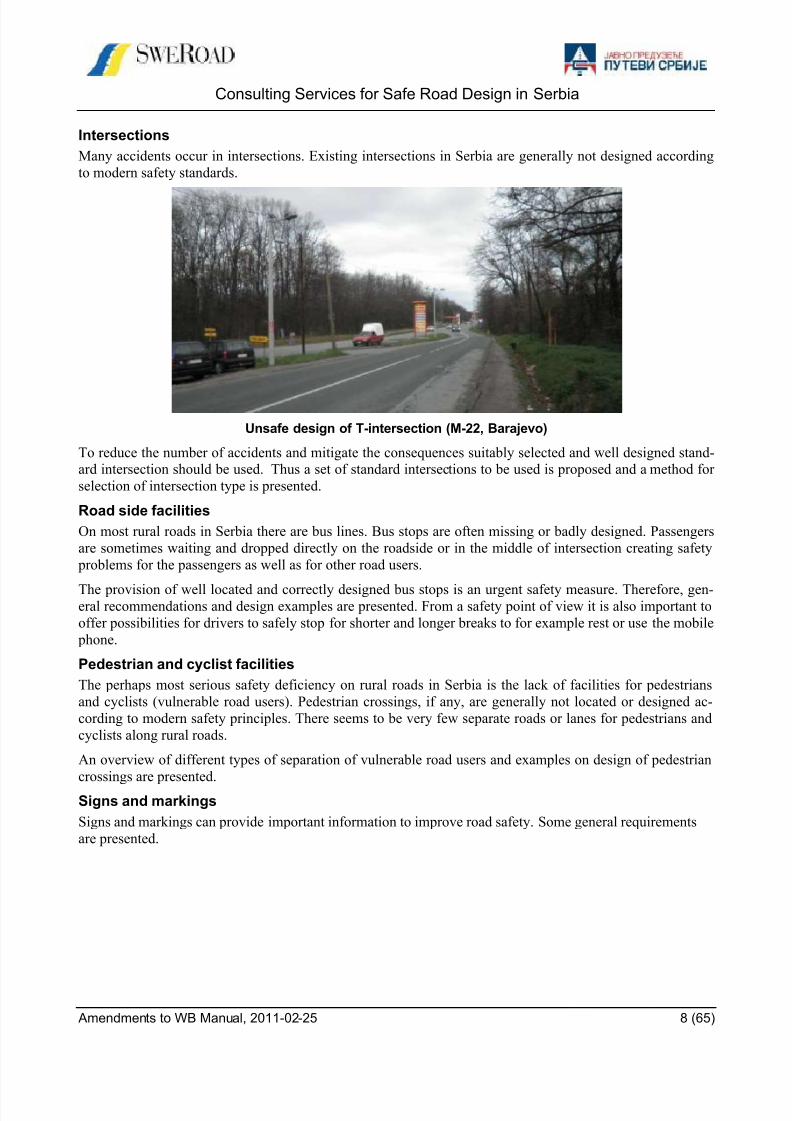
Intersections
Many accidents occur in intersections. Existing intersections in Serbia are generally not designed according
to modern safety standards.
Unsafe design of T-intersection (M-22, Barajevo)
To reduce the number of accidents and mitigate the consequences suitably selected and well designed stand-
ard intersection should be used. Thus a set of standard intersections to be used is proposed and a method for
selection of intersection type is presented.
Road side facilities
On most rural roads in Serbia there are bus lines. Bus stops are often missing or badly designed. Passengers
are sometimes waiting and dropped directly on the roadside or in the middle of intersection creating safety
problems for the passengers as well as for other road users.
The provision of well located and correctly designed bus stops is an urgent safety measure. Therefore, gen-eral recommendations and design examples are presented. From a safety point of view it is also important to
offer possibilities for drivers to safely stop for shorter and longer breaks to for example rest or use the mobile
phone.
Pedestrian and cyclist facilities
The perhaps most serious safety deficiency on rural roads in Serbia is the lack of facilities for pedestrians
and cyclists (vulnerable road users). Pedestrian crossings, if any, are generally not located or designed ac-
cording to modern safety principles. There seems to be very few separate roads or lanes for pedestrians and
cyclists along rural roads.
An overview of different types of separation of vulnerable road users and examples on design of pedestrian
crossings are presented.
Signs and markings
Signs and markings can provide important information to improve road safety. Some general requirements
are presented.

8/9/2019 safe_road_design_manual_amendments_to_wb.pdf
http://slidepdf.com/reader/full/saferoaddesignmanualamendmentstowbpdf 9/65
Consulting Services for Safe Road Design in Serbia
Amendments to WB Manual, 2011-02-25 9 (65)
2 SAFETY CONSIDERATIONS IN DESIGN
People working with road design should have sufficient knowledge about three different aspects of road safe-
ty:
1. General understanding of the road safety problem
2. How to handle safety problems – find the problems and the countermeasures
3. How to take safety considerations in design and equipment of roads
The first aspect includes e.g. the understanding of the need to adapt the infrastructure to the human capabili-
ties and the importance of speed for accident risks and consequences.
The second aspect includes programs like RSA (Road Safety Audit), RSI (Road Safety Inspection), and
BSM (Black Spot Management).
The third aspect includes the design of different road elements - like cross section and intersections - and the
equipment with signs, markings, guardrails etc.
The World Bank manual “Sustainable safe road design” and consequently these amendments, describes dif-ferent parts of those three aspects.
2.1 Design considerations
2.1.1 Introduction
The road network is an integrated part of the society. Thus, road design is influenced by many interacting
factors. The objectives with roads are to achieve positive effects for example to make services and other ac-
tivities available and contribute to the development of the society. However, the construction and use of
roads also causes negative effects. It consumes monetary and natural resources , and creates problems like
accidents and environmental impacts. Roads must also be adapted to different kinds of restrictions like the
capabilities of road users and vehicles, the intended function and the location. Considering the restrictions
roads should be designed to meet the objectives and to avoid the negative effects.
The objectives, restrictions and demands on roads, and consequently in road design, can be illustrated by the
picture below.
Resources
FunctionLocationUsers
Restrictions
Objectives
TransportsDevelopement
Accidents
Problems
Environment
Money
Nature

8/9/2019 safe_road_design_manual_amendments_to_wb.pdf
http://slidepdf.com/reader/full/saferoaddesignmanualamendmentstowbpdf 10/65
Consulting Services for Safe Road Design in Serbia
Amendments to WB Manual, 2011-02-25 10 (65)
2.2 Safety considerations
2.2.1 General Principles
BackgroundThe view on traffic safety and traffic safety work has changed with the development of traffic and the role of
road traffic in the society. In the early years of motorization, cars were looked upon as horse drawn carriages.
Safety measures were mainly focused on vehicle requirements. The development of technology, especially
increased power and speed of motor vehicles, made the comparison with horse-drawn carriages out-of-date.
Safety measures were focused on adapting people to this new traffic situation.
Today, the whole transportation system, of which the road traffic system is one part, is contemplated. Safety
measures are focused on reducing the exposure of risks, eliminating risk factors and reducing the conse-
quences of accidents. Typical measures are speed limits and separation of motorized traffic from other types
of traffic. With this approach, the purpose of traffic safety work in road design is mainly to eliminate the risk
factors and mitigate the consequences of accidents. The long-term objective is that no one should be serious-
ly injured or killed when using the road traffic system as long as the traffic rules are followed.
Injury risks
The risk of being injured or killed in an accident increases considerably with increased speed. In summary,
many studies have shown that:
The number of injury accidents increases with the square of the vehicle speed
The number of fatal accidents increases with the fourth power of the vehicle speed.
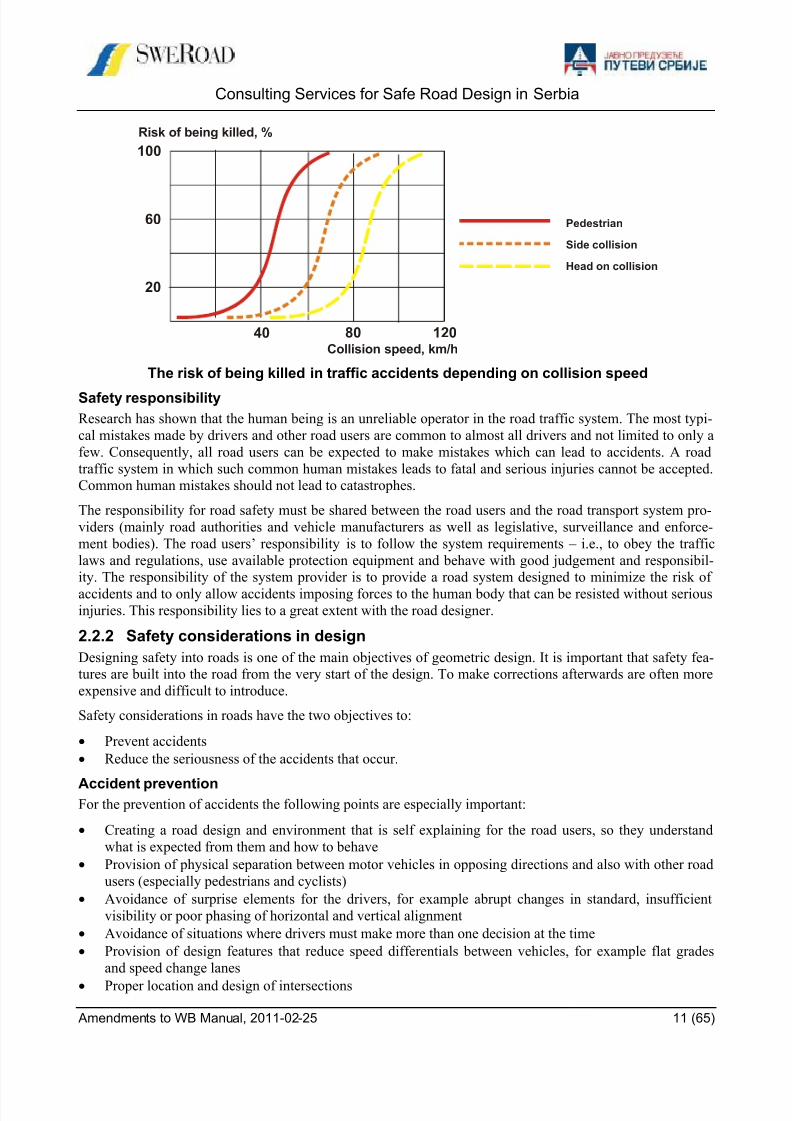
The figure on the next page shows how the risk of being killed in a crash varies with collision speed. The
graph for pedestrians is well supported by research results, while the graphs for vehicle collisions are partly
based on expert assessments.
The graph shows that the risk of being killed increases rather slowly up to a speed where the risk of being
killed is around 10 percent - and then the risk increases rapidly. The conclusion is that a road transport sys-tem should be designed to avoid conflicts at speeds where the risk to be killed is higher than around 10 per-
cent. This means that speeds should not exceed:
30 km/h in a pedestrian/vehicle collision
50 km/h in a side-on vehicle/vehicle or vehicle/object collision
70 km/h in a head-on vehicle/vehicle or vehicle/object collision.
From this, some basic planning and design rules can be derived, for example:
Vulnerable road users should be separated from motor vehicle traffic
At points of conflict between vulnerable road users and motor vehicles, speeds should be low (prefera-
bly 30 km/h or lower)
Intersections should be designed to reduce collision speeds, especially for side-on collisions (preferablyto 50 km/h or lower)
The risk for head on collisions and collisions with rigid objects must be reduced to the greatest possible
extent especially where speed is 70 km/h or higher.
However, measures to lower the speed, for example in intersections, are not sufficient. Measures to reduce
the risk of conflicts and the consequences of collisions must also be taken. Examples of such measures are:
the use of standard type intersections and reducing the number of potential conflict points and the sizes of
conflict areas.
8/9/2019 safe_road_design_manual_amendments_to_wb.pdf
http://slidepdf.com/reader/full/saferoaddesignmanualamendmentstowbpdf 11/65
Consulting Services for Safe Road Design in Serbia
Amendments to WB Manual, 2011-02-25 11 (65)
The risk of being killed in traffic accidents depending on collision speed
Safety responsibility
Research has shown that the human being is an unreliable operator in the road traffic system. The most typi-
cal mistakes made by drivers and other road users are common to almost all drivers and not limited to only a
few. Consequently, all road users can be expected to make mistakes which can lead to accidents. A road
traffic system in which such common human mistakes leads to fatal and serious injuries cannot be accepted.
Common human mistakes should not lead to catastrophes.
The responsibility for road safety must be shared between the road users and the road transport system pro-
viders (mainly road authorities and vehicle manufacturers as well as legislative, surveillance and enforce-
ment bodies). The road users’ responsibility is to follow the system requirements – i.e., to obey the traffic
laws and regulations, use available protection equipment and behave with good judgement and responsibil-
ity. The responsibility of the system provider is to provide a road system designed to minimize the risk of
accidents and to only allow accidents imposing forces to the human body that can be resisted without seriousinjuries. This responsibility lies to a great extent with the road designer.
2.2.2 Safety considerations in design
Designing safety into roads is one of the main objectives of geometric design. It is important that safety fea-
tures are built into the road from the very start of the design. To make corrections afterwards are often more
expensive and difficult to introduce.
Safety considerations in roads have the two objectives to:
Prevent accidents
Reduce the seriousness of the accidents that occur.
Accident preventionFor the prevention of accidents the following points are especially important:
Creating a road design and environment that is self explaining for the road users, so they understand
what is expected from them and how to behave
Provision of physical separation between motor vehicles in opposing directions and also with other road
users (especially pedestrians and cyclists)
Avoidance of surprise elements for the drivers, for example abrupt changes in standard, insufficient
visibility or poor phasing of horizontal and vertical alignment
Avoidance of situations where drivers must make more than one decision at the time
Provision of design features that reduce speed differentials between vehicles, for example flat grades
and speed change lanes
Proper location and design of intersections
20
60
100
40
Pedestrian
Side collision
Head on collision
Risk of being killed, %
Collision speed, km/h
80 120

8/9/2019 safe_road_design_manual_amendments_to_wb.pdf
http://slidepdf.com/reader/full/saferoaddesignmanualamendmentstowbpdf 12/65
Consulting Services for Safe Road Design in Serbia
Amendments to WB Manual, 2011-02-25 12 (65)
Proper design, application and location of traffic signs, road markings and other traffic control devices
Provision of design elements compatible with traffic volumes and type of traffic
Provision of road design compatible with the roads traffic function
Provision of proper drainage of the road surface.Reducing the severity of accidents
A lot can be done to reduce the severity of accidents that we fail to prevent. The basic principles are:
There should be a clear zone (safety zone) along each side of the road that is free from hazards such as
lighting columns, other utility poles, rocks, drainage structures, etc.
Roadside slopes should be as flat as feasible (1:4 or flatter)
Sign posts and other supports which must be located within the clear zone should be of a breakaway
type or protected by guard rail
Safety barriers should be provided to protect vehicles from hitting dangerous obstacles that cannot be re-
moved or made breakaway and also to protect vehicles from running off the road down embankments.
Ripcord WP3 - Best practice on Road Design and Road Environment:
One prerequisite for a safe traffic is that the road design is in accordance with the function of the road. The
road user has to be informed about the function of the road by the road design. To achieve that road users
choose their traffic behaviour in accordance with the function of the road, the design of the road must be self
explaining.
As a second prerequisite, the road and the roadside environment must be designed in such a way that mis-
takes of the drivers do not lead to serious accidents (forgiving roadside environment). Based on information
on road classification in European countries as well as information on road design, the design of the road-
side environment and traffic regulation best practice guidelines on road classification and the design of self
explaining roads will be formulated.
Since most fatalities on rural roads are caused by two types of accidents, information on measures to avoidand to reduce the severity of head-on-collisions and run-off-the-road-collisions will be collected. Based on
validated established measures in European countries the best practice concerning these aspects will be
worked out.
2.3 The four-stage principle
2.3.1 Overview
The four-stage principle should be seen as a general approach to analyses of measures for the road transport
system and not as a strict model that should be applied at some specific planning stage. It was originally
launched in order to manage investment funds, but has been developed to a general planning principle for
management of resources and reduction of the road trans port system’s negative effects.
The principle is constructed on a general transport-type approach, but primarily deals with deficiencies and problems within the road transport system. A basic consideration is that measures outside the road transport
system can reduce the demand for road transport, and thus the requirement for measures within the road
transport system. As a first step therefore, measures outside the road transport system should be tried. After
that, the principle is, to a very large extent, concerned with analyses of measures within the road transport
system.
The four steps involve measures being analysed in the following order:
8/9/2019 safe_road_design_manual_amendments_to_wb.pdf
http://slidepdf.com/reader/full/saferoaddesignmanualamendmentstowbpdf 13/65
Consulting Services for Safe Road Design in Serbia
Amendments to WB Manual, 2011-02-25 13 (65)
2.3.2 Step 1
Measures which reduce the demand for transport and the choice of modes of transport
This step include planning, control, regulation, effect and information bearing on both the transport system
and society at large, in order to reduce the demand for transport or transfer transport to less space-requiring,safer or more environmentally friendly means of conveyance.
2.3.3 Step 2
Measures that give more efficient utilisation of the existing road network
This step include input within control, regulation, effect and information directed towards the various com-
ponents of the road transport system, in order to use the existing road network more efficiently, more safely
and in a more environmentally friendly way.
2.3.4 Step 3
Road improvement measures
This step include improvement measures and rebuilding of existing segments, for example, traffic safetymeasures or load-bearing capacity measures.
2.3.5 Step 4
New investment and major rebuilding measures
This step include rebuilding and new building measures, which often demand new land, for example, new
segments of road.
2.3.6 Application
The four-stage principle describes an approach in the analyses of measures for solving identified prob-
lems and deficiencies. It therefore presupposes that an analysis of deficiencies has been carried out, in
which the existing situation is compared with the transport-policy goals.
An accessible transport system
High transport quality
Positive regional development
Safe traffic
Good environment
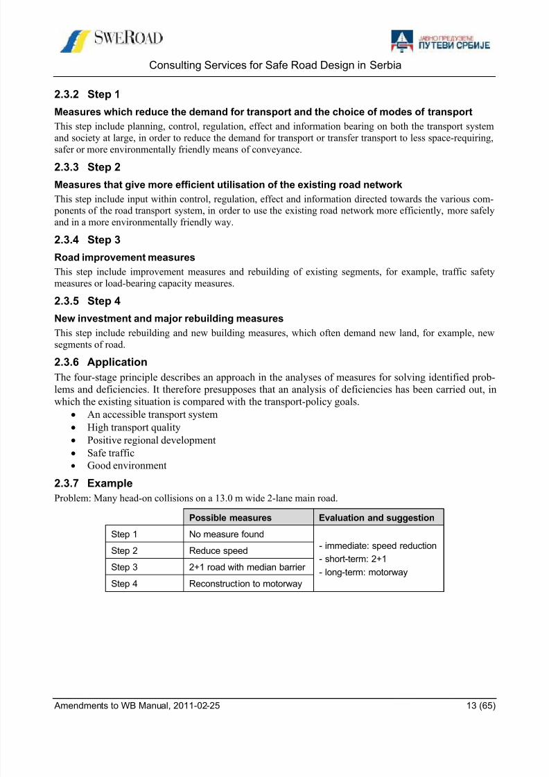
2.3.7 Example
Problem: Many head-on collisions on a 13.0 m wide 2-lane main road.
Possible measures Evaluation and suggestion
Step 1 No measure found
- immediate: speed reduction- short-term: 2+1
- long-term: motorway
Step 2 Reduce speed
Step 3 2+1 road with median barrier
Step 4 Reconstruction to motorway

8/9/2019 safe_road_design_manual_amendments_to_wb.pdf
http://slidepdf.com/reader/full/saferoaddesignmanualamendmentstowbpdf 14/65
Consulting Services for Safe Road Design in Serbia
Amendments to WB Manual, 2011-02-25 14 (65)
3 RURAL ROAD LINKS
3.1 Alignment choice and terrain adaptation
3.1.1 IntroductionTo locate a road in a landscape is a challenge with constraints and possibilities. It is a technical and also an
architectural process.
The main principle is to adapt the road to the surroundings considering technical requirements on sight dis-
tances such as sufficient overtaking possibilities, minimum geometric elements and visual guidance not to
adorn or to emphasize.
3.1.2 Design concepts
Three basic concepts unite and constitute the technical and the architectural process to locate the road in the
landscape:
Scale and form
Space Rhythm.
Scale and form
The landscape can be large-scaled or small-scaled as illustrated in the figure below.
Large-scaled landscape
Small-scaled landscape

8/9/2019 safe_road_design_manual_amendments_to_wb.pdf
http://slidepdf.com/reader/full/saferoaddesignmanualamendmentstowbpdf 15/65
Consulting Services for Safe Road Design in Serbia
Amendments to WB Manual, 2011-02-25 15 (65)
Landscapes can be differentiated in types such as:
Flat landscape
Slightly hilly landscape
Hilly landscape
Space
The space or room is a defined part of the landscape – as far as you can overview from a specific point. The
limitations of the space or room could be:
Terrain (mainly topography), vegetation, buildings
Road design, i.e. cross-section, horizontal and vertical alignment
Crossing bridges and road embankments.
Driver’s space or room concept:
Space limited by ridges and trees
8/9/2019 safe_road_design_manual_amendments_to_wb.pdf
http://slidepdf.com/reader/full/saferoaddesignmanualamendmentstowbpdf 16/65
Consulting Services for Safe Road Design in Serbia
Amendments to WB Manual, 2011-02-25 16 (65)
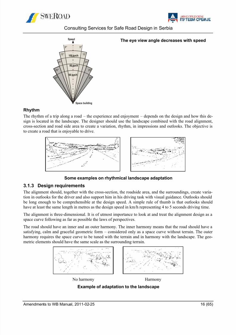
The eye view angle decreases with speed
Rhythm
The rhythm of a trip along a road – the experience and enjoyment – depends on the design and how this de-sign is located in the landscape. The designer should use the landscape combined with the road alignment,
cross-section and road side area to create a variation, rhythm, in impressions and outlooks. The objective is
to create a road that is enjoyable to drive.
Some examples on rhythmical landscape adaptation
3.1.3 Design requirements
The alignment should, together with the cross-section, the roadside area, and the surroundings, create varia-
tion in outlooks for the driver and also support him in his driving task with visual guidance. Outlooks should
be long enough to be comprehensible at the design speed. A simple rule of thumb is that outlooks should
have at least the same length in metres as the design speed in km/h representing 4 to 5 seconds driving time.
The alignment is three-dimensional. It is of utmost importance to look at and treat the alignment design as a
space curve following as far as possible the laws of perspectives.
The road should have an inner and an outer harmony. The inner harmony means that the road should have a
satisfying, calm and graceful geometric form – considered only as a space curve without terrain. The outer
harmony requires the space curve to be tuned with the terrain and in harmony with the landscape. The geo-
metric elements should have the same scale as the surrounding terrain.
No harmony Harmony
Example of adaptation to the landscape
Speed
Space building
37°
29°
20°
15°
9° 9°
15°
20°
29°
37°
100 km/h
80 km/h
60 km/h
8/9/2019 safe_road_design_manual_amendments_to_wb.pdf
http://slidepdf.com/reader/full/saferoaddesignmanualamendmentstowbpdf 17/65
Consulting Services for Safe Road Design in Serbia
Amendments to WB Manual, 2011-02-25 17 (65)
3.2 Overtaking lanes
3.2.1 Definition and design principle
An overtaking lane is an extra lane to left of the through lane to facilitate overtaking in steep ascents or de-
scents or on roads with limited overtaking possibilities.
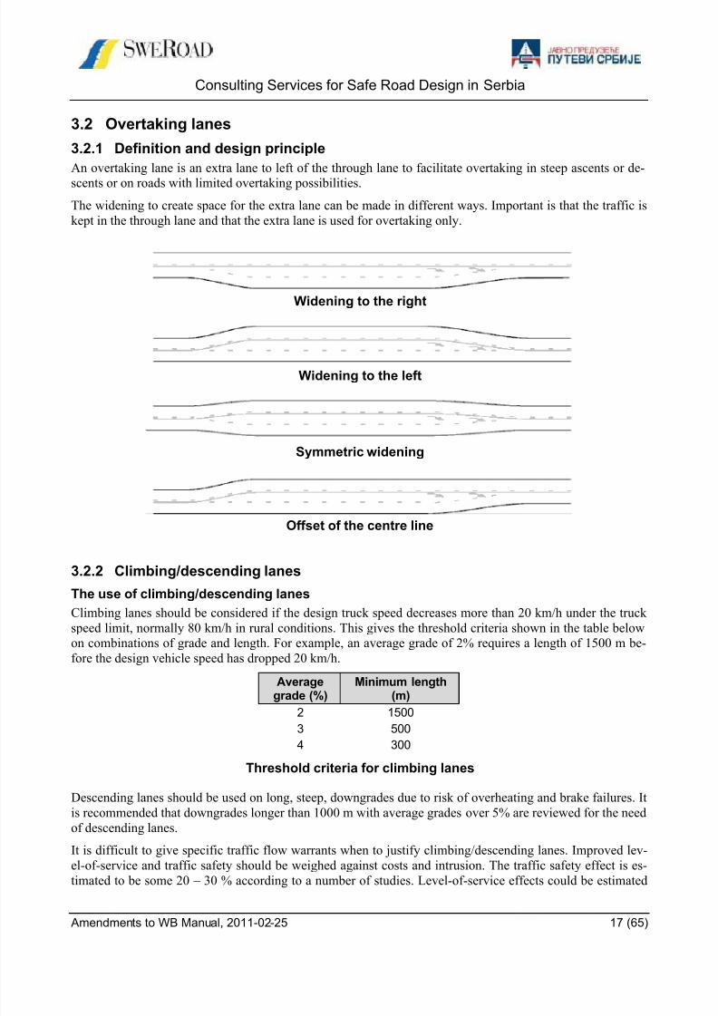
The widening to create space for the extra lane can be made in different ways. Important is that the traffic is
kept in the through lane and that the extra lane is used for overtaking only.
Widening to the right
Widening to the left
Symmetric widening
Offset of the centre line
3.2.2 Climbing/descending lanes
The use of climbing/descending lanes
Climbing lanes should be considered if the design truck speed decreases more than 20 km/h under the truck
speed limit, normally 80 km/h in rural conditions. This gives the threshold criteria shown in the table below
on combinations of grade and length. For example, an average grade of 2% requires a length of 1500 m be-
fore the design vehicle speed has dropped 20 km/h.
Averagegrade (%)
Minimum length(m)
2 15003 500
4 300
Threshold criteria for climbing lanes
Descending lanes should be used on long, steep, downgrades due to risk of overheating and brake failures. It
is recommended that downgrades longer than 1000 m with average grades over 5% are reviewed for the need
of descending lanes.
It is difficult to give specific traffic flow warrants when to justify climbing/descending lanes. Improved lev-
el-of-service and traffic safety should be weighed against costs and intrusion. The traffic safety effect is es-
timated to be some 20 – 30 % according to a number of studies. Level-of-service effects could be estimated

8/9/2019 safe_road_design_manual_amendments_to_wb.pdf
http://slidepdf.com/reader/full/saferoaddesignmanualamendmentstowbpdf 18/65
Consulting Services for Safe Road Design in Serbia
Amendments to WB Manual, 2011-02-25 18 (65)
using the US Highway Capacity Manual and depends to a large extent on traffic flow, ratio of heavy vehicles
and over all alignment. The traffic flows in the table below are suggested.
Grade
%
AADT
design year3-4 3-5000
5-6 2-4000
AADT-volumes to justify climbing/descending lanes
Design
The climbing lane should have full width over the section with design truck speed below 60 km/h with entry
and exit tapers according to the table below. The design should be smooth. At lane-drops the sight distance
should exceed that required for “no overtaking” centreline markings, and should preferably be much more
than this.
Speed(km/h)
Entry taper (m) Exit taper (m)
80
100
150
200
200
300
Entry and exit taper widths
The climbing lane width should normally be 3.5 m. but this can be relaxed to 3.0 m where space is limited.
The paved shoulder width should be unchanged, as the shoulder will continue to be used by pedestrians and
cyclists.
Speed profile
The speed profile graph can be used to assess truck speed behaviour on combined vertical alignments asshown in the following example.
Example profile
0
10
20
30
40
50
60
70
P1
P1P2
P2
P3
P3
P4
P4
H (m)
0 500 1000 1500 2000 L (m)
Rv 5000 6% Rv 7000 -2%0%Profile
Real profile
Approximate profile
Approximative profile
Element L (m) i (%)
150150
1150
1460
0
1000 6
310 0
Long -2
L (m)

8/9/2019 safe_road_design_manual_amendments_to_wb.pdf
http://slidepdf.com/reader/full/saferoaddesignmanualamendmentstowbpdf 19/65
Consulting Services for Safe Road Design in Serbia
Amendments to WB Manual, 2011-02-25 19 (65)
3.2.3 Overtaking lane
Overtaking lanes can be used on roads with median separation (see 2+1 or 1+1 roads) or with limited over-
taking possibilities. A typical design of an overtaking lane is shown in the figure below.
Typical design of an overtaking lane
3.3 Median separation
3.4 Type of separation
The separation can be made with or without a median barrier. From a safety point of view a median barrier is
preferred, and should always be used when the road is wide enough.
Separation with median barrier Separation without median barrier
If the road width is not sufficient to install a median barrier, centre line crossings can be limited by a centre
line marking reinforced with cat-eyes or milled rumble strips. Based on Swedish experiences milled rumble
strips is recommended for Serbia based on problem with cat-eyes for winter maintenance.
Median barrier Milled median rumble strips
8/9/2019 safe_road_design_manual_amendments_to_wb.pdf
http://slidepdf.com/reader/full/saferoaddesignmanualamendmentstowbpdf 20/65
8/9/2019 safe_road_design_manual_amendments_to_wb.pdf
http://slidepdf.com/reader/full/saferoaddesignmanualamendmentstowbpdf 21/65
Consulting Services for Safe Road Design in Serbia
Amendments to WB Manual, 2011-02-25 21 (65)
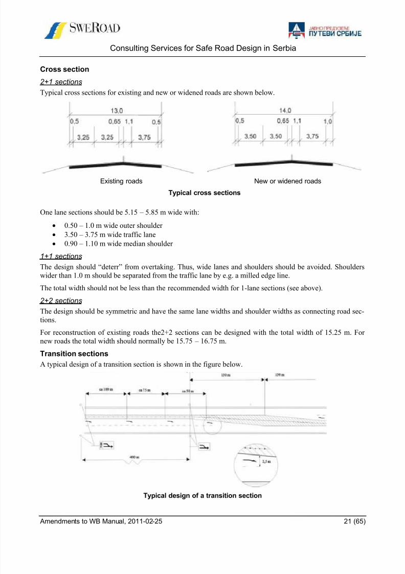
Cross section
2+1 sections
Typical cross sections for existing and new or widened roads are shown below.
Existing roads New or widened roads
Typical cross sections
One lane sections should be 5.15 – 5.85 m wide with:
0.50 – 1.0 m wide outer shoulder
3.50 – 3.75 m wide traffic lane
0.90 – 1.10 m wide median shoulder
1+1 sections
The design should “deterr” from overtaking. Thus, wide lanes and shoulders should be avoided. Shoulders
wider than 1.0 m should be separated from the traffic lane by e.g. a milled edge line.
The total width should not be less than the recommended width for 1-lane sections (see above).
2+2 sectionsThe design should be symmetric and have the same lane widths and shoulder widths as connecting road sec-
tions.
For reconstruction of existing roads the2+2 sections can be designed with the total width of 15.25 m. For
new roads the total width should normally be 15.75 – 16.75 m.
Transition sections
A typical design of a transition section is shown in the figure below.
Typical design of a transition section
8/9/2019 safe_road_design_manual_amendments_to_wb.pdf
http://slidepdf.com/reader/full/saferoaddesignmanualamendmentstowbpdf 22/65
Consulting Services for Safe Road Design in Serbia
Amendments to WB Manual, 2011-02-25 22 (65)
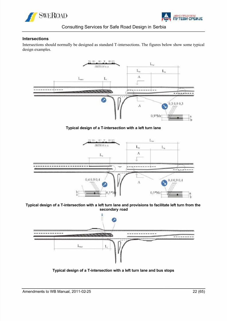
Intersections
Intersections should normally be designed as standard T-intersections. The figures below show some typical
design examples.
Typical design of a T-intersection with a left turn lane
Typical design of a T-intersection with a left turn lane and provisions to facilitate left turn from thesecondary road
Typical design of a T-intersection with a left turn lane and bus stops
8/9/2019 safe_road_design_manual_amendments_to_wb.pdf
http://slidepdf.com/reader/full/saferoaddesignmanualamendmentstowbpdf 23/65
Consulting Services for Safe Road Design in Serbia
Amendments to WB Manual, 2011-02-25 23 (65)
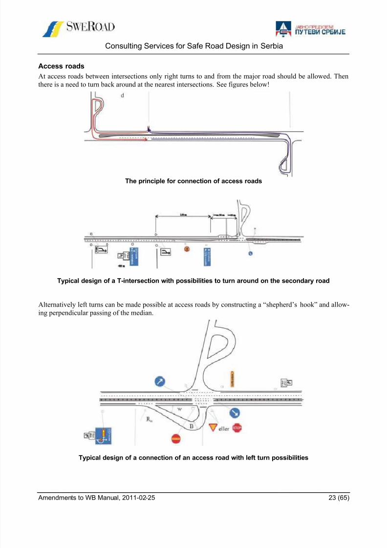
Access roads
At access roads between intersections only right turns to and from the major road should be allowed. Then
there is a need to turn back around at the nearest intersections. See figures below!
The principle for connection of access roads
Typical design of a T-intersection with possibilities to turn around on the secondary road
Alternatively left turns can be made possible at access roads by constructing a “shepherd’s hook” and allow-
ing perpendicular passing of the median.
Typical design of a connection of an access road with left turn possibilities
8/9/2019 safe_road_design_manual_amendments_to_wb.pdf
http://slidepdf.com/reader/full/saferoaddesignmanualamendmentstowbpdf 24/65
Consulting Services for Safe Road Design in Serbia
Amendments to WB Manual, 2011-02-25 24 (65)
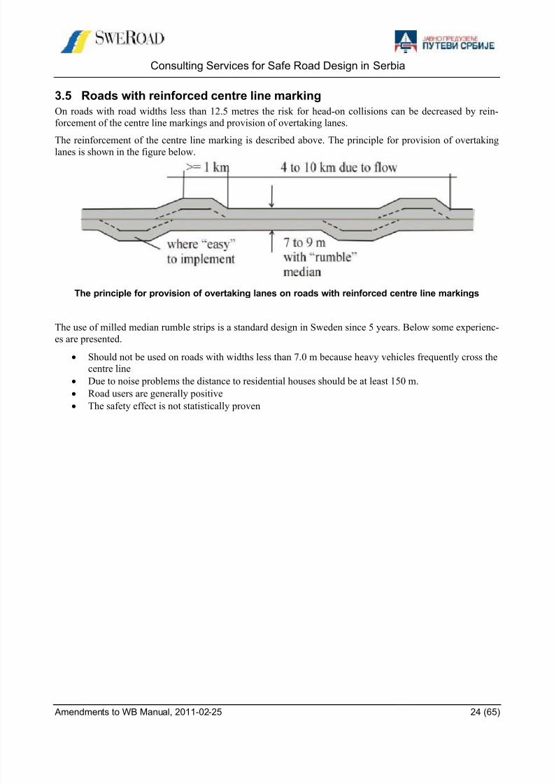
3.5 Roads with reinforced centre line marking
On roads with road widths less than 12.5 metres the risk for head-on collisions can be decreased by rein-
forcement of the centre line markings and provision of overtaking lanes.
The reinforcement of the centre line marking is described above. The principle for provision of overtakinglanes is shown in the figure below.
The principle for provision of overtaking lanes on roads with reinforced centre line markings
The use of milled median rumble strips is a standard design in Sweden since 5 years. Below some experienc-
es are presented.
Should not be used on roads with widths less than 7.0 m because heavy vehicles frequently cross the
centre line
Due to noise problems the distance to residential houses should be at least 150 m.
Road users are generally positive
The safety effect is not statistically proven
8/9/2019 safe_road_design_manual_amendments_to_wb.pdf
http://slidepdf.com/reader/full/saferoaddesignmanualamendmentstowbpdf 25/65
Consulting Services for Safe Road Design in Serbia
Amendments to WB Manual, 2011-02-25 25 (65)
3.6 Roadside barriers
3.6.1 The use of roadside barriers
PurposeThe purpose of roadside barriers is to prevent vehicles from running off the road and hitting or falling into a
hazard - such as hitting an obstruction near the edge of the road or falling down a steep slope or into a river.
When a roadside hazard is identified measures should be considered in the following order:
1. remove the hazard
2. make it less hazardous
3. shield the hazard with a barrier
However, safety barrier is a hazard in itself. Collision with a barrier can cause serious injuries, particularly to
riders of two-wheelers. This means that safety barrier should only be installed when the consequences of an
out-of-control vehicle hitting the unprotected hazard are likely to be more severe than those of impact with
the safety barrier.
It is not economic to try and shield every hazard. The risk increases with traffic volume, traffic speed, and
road curvature. Cost-benefit analysis can help determine if it is advisable to install a barrier.
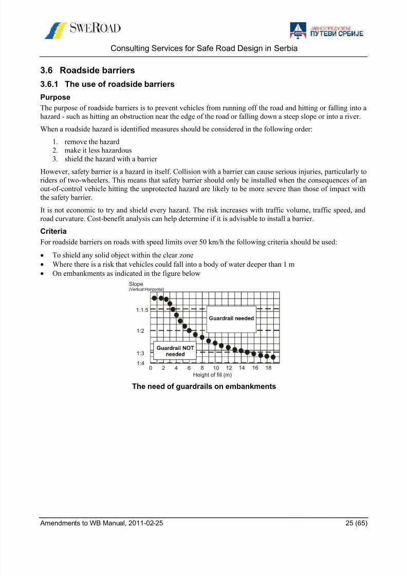
Criteria
For roadside barriers on roads with speed limits over 50 km/h the following criteria should be used:
To shield any solid object within the clear zone
Where there is a risk that vehicles could fall into a body of water deeper than 1 m
On embankments as indicated in the figure below
The need of guardrails on embankments
Slope(Vertical:Horizontal)
0 10 12 14 16 18864
Height of fill (m)
2
1:1.5
1:2
1:4
1:3

8/9/2019 safe_road_design_manual_amendments_to_wb.pdf
http://slidepdf.com/reader/full/saferoaddesignmanualamendmentstowbpdf 26/65
Consulting Services for Safe Road Design in Serbia
Amendments to WB Manual, 2011-02-25 26 (65)
3.6.2 Design
Length of need
To keep costs down roadside barriers are often too short to be effective. Generally the barrier must be at least
30 m to perform satisfactorily. On a two-way single carriageway road both directions of travel must be con-sider.
The calculation of the length of need according to the Swedish guidelines is shown below.
Determining the length of need
The total length of the guardrail is a+b+c+2d where:
a = the length of the hazard parallel to the road
b = the needed length before the hazard according to the diagram below
c = b/2
d = terminal length (normally 12 m)
110 km/h
90 km/h
70 km/h
50 km/h
50 km/h
low standard
Distance f (m)
L e n g t h b ( m
)

8/9/2019 safe_road_design_manual_amendments_to_wb.pdf
http://slidepdf.com/reader/full/saferoaddesignmanualamendmentstowbpdf 27/65
Consulting Services for Safe Road Design in Serbia
Amendments to WB Manual, 2011-02-25 27 (65)
Lateral placement
The area between the carriageway and the guardrail should normally be designed according to the general
rules for smoothed roadside areas, i.e. with maximum height differences of some 5 cm and slopes maximum
1:6 to allow a controlled guard-rail hit.
Normal lateral placement of barriers
The barrier should normally be placed at least 0.5 meters from the carriageway. Normal beam types shouldhave a back support of about 0.5 m before the slope starts.
The distance to the obstacle is determined by the working width for the barrier type. The clear zone between
the guardrail and the fixed object should be at least as wide as the working width of the guardrail.
Alternative lateral placement of barriers
Barrier terminals
The end of a steel beam guardrail is a major hazard, as vehicles can become impaled on it. There is no whol-
ly safe way of terminating guardrail but the main options are:
flare the end section of the guardrail away from the edge of the shoulder and ramp the beam down into
the ground
use a special impact-absorbing terminals
On a two-way road both the upstream and downstream ends of the guardrail will need to be terminated in the
above way. One of the problems of ramped ends is that they can launch out-of-control vehicles into the air,
with disastrous consequences. Flaring is an effective way of reducing the risk of impact but this can be diffi-cult to achieve in some situations, such as on narrow embankments.
Eample on flaring of the end of guardrail
>=working width
height difference>5 cmshould be smoothed
traversablemax 1:6 recommended1:4 absolute minimum
Direction of travel
1140
1:10 Parabolic flare L=11400
Post spacing = 1905
End section tobe rampeddown

8/9/2019 safe_road_design_manual_amendments_to_wb.pdf
http://slidepdf.com/reader/full/saferoaddesignmanualamendmentstowbpdf 28/65
Consulting Services for Safe Road Design in Serbia
Amendments to WB Manual, 2011-02-25 28 (65)
3.6.3 Barriers types
There are three main types of barriers:
steel beam guardrail
wire rope barrier concrete barrier
Steel beam guardrail
Steel beam guardrail is the most common type of safety barrier. It consists of a W-shaped steel beam mount-
ed on steel posts. A typical height is 550 mm above the height of the road surface. The containment capabil-
ity can be increased by using two beams, one mounted above the other.
Concrete barrier
Concrete barriers are strong enough to stop most out-of-control vehicles, and being rigid there is no deflec-
tion on impact. This makes them suitable for use on narrow medians and where it is essential to keep vehi-
cles on the road, such as at bridges. Small angle impacts usually result in little damage to the vehicle. How-
ever, large angle impacts tend to result in major damage to the vehicle, and severe injuries to the occupants.
Research has shown that the conventional profile (commonly called New Jersey Barrier) tends to cause small
vehicles to overturn, and the preferred shape is now a vertical or near-vertical wall. Concrete barrier general-
ly requires very little routine maintenance except after very severe impacts.
Wire rope barrier
Wire rope barriers are often used as median barriers, but can also be used as roadside barriers. The barrier is
usually 550 -700 mm high and the diameter of the wires around 20 mm. There are several types of wire rope
barriers. The number and placement of wires and the post cross section vary. The figure to the right shows
some typical designs.
3.6.4 Barrier performance
The safety barrier should perform to prevent vehicles from passing through the barrier and enable the drivers
to retain control of the vehicle. In order to do so the barrier should absorb the impact of the vehicle withoutinjuring the occupants (no severe deceleration) re-direct the vehicle along the road parallel to the barrier.
Consequently, the performance is depending on barrier design and barrier material.
Impact speed and angle
Conventional safety barriers are designed for impacts by passenger cars travelling at 65 km/h hitting the bar-
rier at a 25 degree angle. Barriers can be made that will cope with trucks and buses, but the high cost means
that they can only be justified in exceptionally risky situations.
Most barriers will not perform well when hit at a large angle - such as can happen when barrier is installed
on the outside of a sharp bend.
Deflection
The maximum permissible deflection is an important consideration. The deflection varies with the type of
barrier. The table below shows a classification as to deflection.
Category Type Deflection Comments
Rigid Concrete ≈ 0 Expensive, low maintenance costs
Semi-rigid Steel beam ≤ 1 m Performs well in moderate-speed situations
Flexible Wire rope ≥ 1 m Expensive; technically complicated; quick to repair
Classification of safety barriers as to deflection

8/9/2019 safe_road_design_manual_amendments_to_wb.pdf
http://slidepdf.com/reader/full/saferoaddesignmanualamendmentstowbpdf 29/65
Consulting Services for Safe Road Design in Serbia
Amendments to WB Manual, 2011-02-25 29 (65)
3.7 Forgiving roadside
3.7.1 Definition
“Forgiving roadside” is also called “clear roadside area” or “obstacle free zoon”.
The clear zone is a safety zone adjacent to the traffic lanes. It provides space for a driver to recover control
of his vehicle if he is in danger of running off the road. The clear zone must:
Be free of hazardous objects (such as posts, trees etc) and other hazards
Have a smooth design with no steep slopes, open drains, etc.
There are a number of empirical studies in Europe and US indicating major safety benefits from clear zones.
It is obvious that the need for clear zones increases with speed and curvature.
3.7.2 Width
The following clear zone widths, measured from the edge of the traffic lane, are considered to give an ac-
ceptable standard of safety. Traffic volume is also a factor, as, generally, the higher the traffic volume the
greater the frequency of run-off-road incidents – which supports the use of wider clear zone widths.
Speed(km/h)
Standard
Desired Minimum
70 5 m 3 m
80 6 m 4 m
100 9 m 6 m
Clear zone widths
The clear zone widths given in table above should be increased at sharp bends on high-speed roads according
to the diagram below.
Clear zone correction factor for bends
Example: Radius 700 m and speed limit 100 gives the correction factor 1.6.
Desired clear zone is extended from 9 m to 1.6 * 9 = 14.4 m
Front slopes steeper than 1:3 cannot be counted as part of the clear zone because they are too steep. Slopes
that can be traversed safely by out-of-control vehicles need to be at least 1:4 or gentler. Slopes between 1:3
and 1:4 are marginal; the normal practice is that half the width of these slopes is counted as part of the clear
zone – see the figure on the next page.
0
1
2
300 400 500 600 700 800 900 1000 1100 1200
Speed limit 100 km/h
Speed limit 80 km/h
Radius (m)
Correction factor

8/9/2019 safe_road_design_manual_amendments_to_wb.pdf
http://slidepdf.com/reader/full/saferoaddesignmanualamendmentstowbpdf 30/65
Consulting Services for Safe Road Design in Serbia
Amendments to WB Manual, 2011-02-25 30 (65)
Example how to calculate clear zones
3.7.3 Fixed Objects
There should be no hazardous objects, sometimes called fixed objects, in the clear zone. A fixed object is
rigid object close to the road, which constitutes a safety hazard for road users.
The object must be rigid to be a fixed object. Posts for traffic signs are normally not considered fixed ob-
jects.
The object should also be close to the road to be a fixed object. From a safety point of view that means up to
about 5 meters from the edge of the road depending on the speed.
The following objects are some examples on fixed objects:
Electricity Pole
Telecom Pole
Lamp Post
Other Rigid Post Information Traffic Sign of Concrete
Bus Shelter
Tree (diameter >0.1 m)
Rock
Such objects should be removed, made “softer” (e.g. break -away lighting poles) or shielded by a safety bar-
rier.
3.7.4 Road Side Design
Transition to carriageway
Safety zones should be designed with the objective to give a small risk for turnover and skid accidents. Thisindicates that the height difference between the overlay and the adjacent strip should not exceed some 5 cm
without smoothing measures, which could be grades at least 1:6.
Side slopes
The shallower the slope, the safer it will be. And the transition from the shoulder to the front slope must be
smooth enough to prevent the vehicle becoming airborne. A safe transition is also needed between the front
slope and the back slope so as to avoid causing the vehicle to rollover. The figures on the next page show the
principles of smooth roadside area design. The front slope should be 1:4 or gentler. The transition at the top
and toe of the slope should be smooth. The height difference H between the shoulder and the support strip
should not be more than 50 mm
1.5 1.0
1:2
Available clear zone:
1.5 + 4.0 + 0.5*3.0 + 2.0 = 9 m
1:4
1:3
4.0 3.0 2.0
8/9/2019 safe_road_design_manual_amendments_to_wb.pdf
http://slidepdf.com/reader/full/saferoaddesignmanualamendmentstowbpdf 31/65
Consulting Services for Safe Road Design in Serbia
Amendments to WB Manual, 2011-02-25 31 (65)
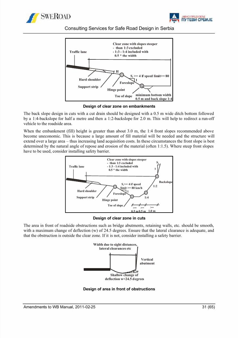
Design of clear zone on embankments
The back slope design in cuts with a cut drain should be designed with a 0.5 m wide ditch bottom followed
by a 1:4-backslope for half a metre and then a 1:2-backslope for 2.0 m. This will help to redirect a run-offvehicle to the roadside area.
When the embankment (fill) height is greater than about 3.0 m, the 1:4 front slopes recommended above
become uneconomic. This is because a large amount of fill material will be needed and the structure will
extend over a large area – thus increasing land acquisition costs. In these circumstances the front slope is best
determined by the natural angle of repose and erosion of the material (often 1:1.5). Where steep front slopes
have to be used, consider installing safety barrier.
Design of clear zone in cuts
The area in front of roadside obstructions such as bridge abutments, retaining walls, etc. should be smooth,
with a maximum change of deflection (w) of 24.5 degrees. Ensure that the lateral clearance is adequate, and
that the obstruction is outside the clear zone. If it is not, consider installing a safety barrier.
Design of area in front of obstructions
Hinge point
Traffic lane
Hard shoulder
Support strip
Toe of slope minimum bottom width 0.5 m and back slope 1:4
Clear zone with slopes steeper
- than 1:3 excluded- 1:3 - 1:4 included with
0.5 * the width
1
S >= 4 if speed limit>= 80f
H
Foreslope
Hinge point
Traffic lane
1:2
1:4
Hard shoulder
Support strip
Toe of slope>=
0.5 m
>=0.5 m
>=1.0 m
Clear zone with slopes steeper- than 1:3 excluded- 1:3 - 1:4 included with
0.5 * the width
1
S >= 4 if speed
limit >= 80 km/hf
Sb
1
Foreslope
Backslope
Width due to sight distances,lateral clearances etc
Verticalabutment
wShallow change of
deflection w<24.5 degrees
8/9/2019 safe_road_design_manual_amendments_to_wb.pdf
http://slidepdf.com/reader/full/saferoaddesignmanualamendmentstowbpdf 32/65
Consulting Services for Safe Road Design in Serbia
Amendments to WB Manual, 2011-02-25 32 (65)
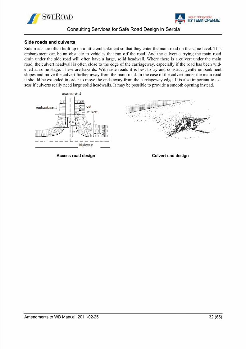
Side roads and culverts
Side roads are often built up on a little embankment so that they enter the main road on the same level. This
embankment can be an obstacle to vehicles that run off the road. And the culvert carrying the main road
drain under the side road will often have a large, solid headwall. Where there is a culvert under the mainroad, the culvert headwall is often close to the edge of the carriageway, especially if the road has been wid-
ened at some stage. These are hazards. With side roads it is best to try and construct gentle embankment
slopes and move the culvert further away from the main road. In the case of the culvert under the main road
it should be extended in order to move the ends away from the carriageway edge. It is also important to as-
sess if culverts really need large solid headwalls. It may be possible to provide a smooth opening instead.
Access road design Culvert end design

8/9/2019 safe_road_design_manual_amendments_to_wb.pdf
http://slidepdf.com/reader/full/saferoaddesignmanualamendmentstowbpdf 33/65

8/9/2019 safe_road_design_manual_amendments_to_wb.pdf
http://slidepdf.com/reader/full/saferoaddesignmanualamendmentstowbpdf 34/65
Consulting Services for Safe Road Design in Serbia
Amendments to WB Manual, 2011-02-25 34 (65)
Distances 30 km/h 50 km/h 70 km/h
h to obstacle higher than 0,2 m 0,5 0,9 1,2
c to kerbstone 0,2 0,4 0,7
v heavy vehicle and bus width 2,6 2,6 2,6
passenger car width 1,8 1,8 1,8
a between meeting or passing vehicles 0,7 1,0 1,3
p between parked vehicle and kerbstone 0,1 0,1 0,1
Example on vehicle widths and needed cross-section widths
For example, the width between the curbstones for a two-lane road or for one roadway of a two-lane divided
road according to the figure (except for the walls) will be:
Design speed 30 km/h: 0,2+2.6+0.7+2.6+0.2 = 6.3 m
Design speed 50 km/h: 0.4+2.6+1.0+2.6+0.4 = 7.0 m
Design speed 70 km/h: 0.7+2.6+1.3+2.6+0.7 = 7.9 m
4.2.3 Intersections
Reduction of number of intersections
One way to increase the safety on through roads is to reduce the number of intersections. However, too long
distances between intersections may increase the speed and also increase the traffic volumes in the local
streets.
Replacement of 4-way intersections
Two 3-way intersections are generally safer than one 4-way intersection. Uncontrolled 4-way intersections
should therefore be avoided and if possible replaced by a roundabout or split into two 3-way intersections.
RoundaboutsIf possible, every intersection on through roads should be designed as a roundabout, because:
It is the safest intersection type. Both the number and the severity of accidents are decreased com-
pared to other types of intersections
It reduces the vehicle speed for all traffic and allows the traffic to flow smoothly.
Signalized intersections
Signalized intersections can be used if:
there is a system of coordinated signalized intersections
the available space is too limited for a roundabout
the traffic volume is very high on the through road and low on the secondary road
c v a v c

8/9/2019 safe_road_design_manual_amendments_to_wb.pdf
http://slidepdf.com/reader/full/saferoaddesignmanualamendmentstowbpdf 35/65
Consulting Services for Safe Road Design in Serbia
Amendments to WB Manual, 2011-02-25 35 (65)
4.2.4 Pedestrian crossings
Need and location
The need for pedestrian crossings is depending on the number of crossing pedestrians and the traffic volume.
The following diagram shows a Swedish recommendation for when pedestrian crossings are needed.
Example of a diagram to determine the need for pedestrian crossings
Pedestrian crossings should be located to places where the vehicle speed can be reduced to 30 km/h. Gener-
ally, pedestrian crossings are located at intersections.
Design of separate pedestrian crossings
Pedestrian crossing on a 2-lane through road
Pedestrian crossings should be constructed with a traffic island to make it possible to pass the road in stages
and to make the crossing clearly visible to drivers. On roads with low traffic volumes and few heavy vehi-
cles, the crossing can be raised over the travelled way to reduce the speed and to make it more convenient for
the pedestrians.Pedestrian crossing on a 4-lane through road
On divided roads, pedestrian crossings can be designed with a side displacement in the median to force the
pedestrians to turn and face the oncoming traffic before crossing the road.
Pedestrian crossing on a 2-lane through road Pedestrian crossing on a 4-lane through road
Restrictions for pedestrians
On through roads class I and II, pedestrians are not expected to cross the road in other places than at intersec-
tions and special pedestrian crossings (through road class II). To ensure this, it can be necessary to install
fences or other kinds of barriers along the road or in the median on sections were pedestrians otherwise can
be expected to cross the road.
Pedestrians / h
500
400 Pedestrian crossing needed
300
200
Pedestrian crossing not needed
100
200 400 600 800 1000
Vehicles / h
8/9/2019 safe_road_design_manual_amendments_to_wb.pdf
http://slidepdf.com/reader/full/saferoaddesignmanualamendmentstowbpdf 36/65
Consulting Services for Safe Road Design in Serbia
Amendments to WB Manual, 2011-02-25 36 (65)
4.3 Example on design of roads through built up areas
This section presents an example to show how roads through built up areas can be classified and designed. It
should not be used in Serbia without adaptation to Serbian conditions.
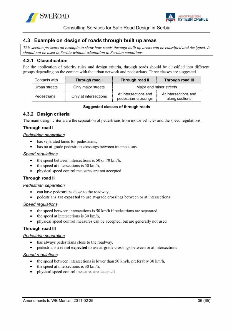
4.3.1 Classification
For the application of priority rules and design criteria, through roads should be classified into different
groups depending on the contact with the urban network and pedestrians. Three classes are suggested.
Contacts with Through road I Through road II Through road III
Urban streets Only major streets Major and minor streets
Pedestrians Only at intersections At intersections andpedestrian crossings
At intersections andalong sections
Suggested classes of through roads
4.3.2 Design criteriaThe main design criteria are the separation of pedestrians from motor vehicles and the speed regulations.
Through road I
Pedestrian separation
has separated lanes for pedestrians,
has no at-grade pedestrian crossings between intersections
Speed regulations
the speed between intersections is 50 or 70 km/h,
the speed at intersections is 50 km/h,
physical speed control measures are not accepted
Through road II
Pedestrian separation
can have pedestrians close to the roadway,
pedestrians are expected to use at-grade crossings between or at intersections
Speed regulations
the speed between intersections is 50 km/h if pedestrians are separated,
the speed at intersections is 30 km/h,
physical speed control measures can be accepted, but are generally not used
Through road III
Pedestrian separation
has always pedestrians close to the roadway,
pedestrians are not expected to use at-grade crossings between or at intersections
Speed regulations
the speed between intersections is lower than 50 km/h, preferably 30 km/h,
the speed at intersections is 30 km/h,
physical speed control measures are accepted

8/9/2019 safe_road_design_manual_amendments_to_wb.pdf
http://slidepdf.com/reader/full/saferoaddesignmanualamendmentstowbpdf 37/65
Consulting Services for Safe Road Design in Serbia
Amendments to WB Manual, 2011-02-25 37 (65)
4.3.3 Suggested cross-sections
Based on the needed widths and the Swedish guidelines, the standard cross-sections below are suggested.
The figures show two-lane roads, but can be applied for one direction of a four-lane divided road.
Through road I
Pedestrians are completely separated. At places where there are pedestrians close to the road, for example at
houses and where there are pedestrian lanes, fences should be installed.
Proposed standard cross-section for through road class I (70 km/h)
Through road II
Pedestrians are expected to use pedestrian crossings. If necessary, fences should be installed to direct the
pedestrians to these crossings.
Proposed standard cross-section for through road class II (50 km/h)
Through road III
Pedestrians can be expected to cross the road anywhere. If necessary, parking lanes can be accepted.
Proposed standard cross-section for through road class III (50 km/h)
Side reserve(with fence)
Travelled way Side reservewith fence
Pedestrianlane
varies 0,7 2,6 1,3 2,6 0,7 varies varies
8,0 m
Sidewalk Travelled way Side reserve(with fence)
Pedestrianlane
varies 0,4 2,6 1,0 2,6 0,4 varies varies
7,0 m
Sidewalk Parking Travelled way Sidewalk or premise
varies 0,1 2,6 0.2 0,4 2,6 1,0 2,6 0,4 varies
3,0 m 7,0 m

8/9/2019 safe_road_design_manual_amendments_to_wb.pdf
http://slidepdf.com/reader/full/saferoaddesignmanualamendmentstowbpdf 38/65
Consulting Services for Safe Road Design in Serbia
Amendments to WB Manual, 2011-02-25 38 (65)
4.4 Traffic calming
4.4.1 Introduction
Traffic Calming is a term often used for speed management in built-up areas. The basis for speed manage-
ment should be created by road planning, e.g. a by-pass for the long-distance traffic, and by a road design
adapted to the desired speed, e.g. cross-section and intersection design. Nevertheless, sometimes special
speed control measures are necessary.
Speed control measures are mainly used in built-up areas. However, some of the measures can also be used
in other situations, such as in advance of hazardous bends or bridges.
4.4.2 General principles
The standard sequence of speed control measures is:
Rumble strips
Gate
Speed controlled section – with humps, narrowings or chicanes
Standard speed control layout
The preferred and maximum intervals between speed control measures for different desired speeds are given
in the table below.
Desired speed
Interval between speed controldevices
Preferred Maximum
30 km/h 50 m 125 m
50 km/h 125 m 175 m
Maximum intervals between speed control measures
Speed control should preferably be located where judged reasonable for drivers. Pedestrian crossings can be
combined with humps. Speed control is most effectively achieved by humps. Other measures are rumble
strips, gates, narrowings and chicanes.
Speed limit zone
GateCentral speed
control section
Sidewalks Gate
Rumblestrips
Rumblestrips
8/9/2019 safe_road_design_manual_amendments_to_wb.pdf
http://slidepdf.com/reader/full/saferoaddesignmanualamendmentstowbpdf 39/65
Consulting Services for Safe Road Design in Serbia
Amendments to WB Manual, 2011-02-25 39 (65)
4.5 Speed control measures
4.5.1 Rumble strips
Use of rumble stripsRumble strips are transverse strips across the road used to alert and warn drivers with a vibratory and audible
effect before a hazard such as a sharp bend, an intersection or a lower speed limit at the entry to a built-up
area. Warning signs are not normally needed when the strips are built to the specifications given below.
Research in other countries indicates that speed reduction effects tend to be minor and also erode over time.
Therefore, rumble strips should not be used alone to reduce speeds.
Rumble strips should be used as an introduction to a speed control zone but can also be used for example in
the following situations:
before a local speed limit
at an approach to a dangerous intersection
before a sharp bend before a hump
Rumble strips create disturbing noises and can cause vibration problems on soft ground and should be avoid-
ed near dwelling-houses, schools, hospitals, etc.
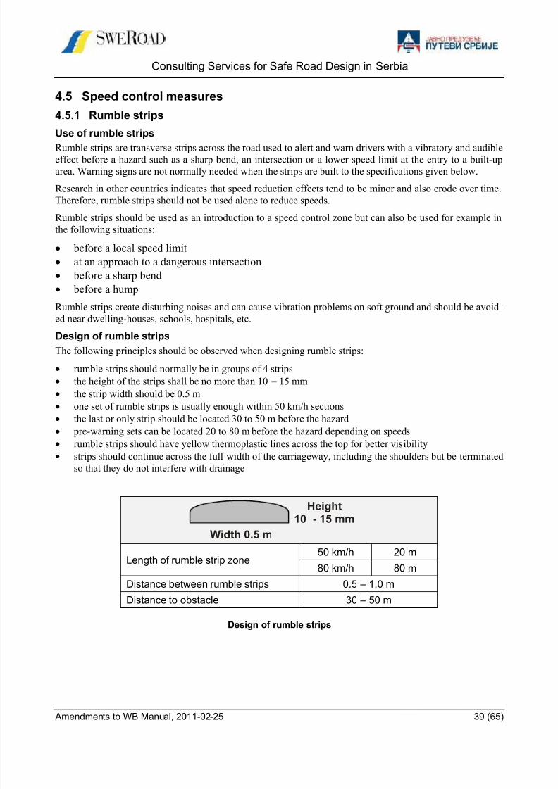
Design of rumble strips
The following principles should be observed when designing rumble strips:
rumble strips should normally be in groups of 4 strips
the height of the strips shall be no more than 10 – 15 mm
the strip width should be 0.5 m
one set of rumble strips is usually enough within 50 km/h sections
the last or only strip should be located 30 to 50 m before the hazard
pre-warning sets can be located 20 to 80 m before the hazard depending on speeds
rumble strips should have yellow thermoplastic lines across the top for better visibility
strips should continue across the full width of the carriageway, including the shoulders but be terminated
so that they do not interfere with drainage
Length of rumble strip zone 50 km/h 20 m80 km/h 80 m
Distance between rumble strips 0.5 – 1.0 m
Distance to obstacle 30 – 50 m
Design of rumble strips
Width 0.5 m
Height10 - 15 mm

8/9/2019 safe_road_design_manual_amendments_to_wb.pdf
http://slidepdf.com/reader/full/saferoaddesignmanualamendmentstowbpdf 40/65
Consulting Services for Safe Road Design in Serbia
Amendments to WB Manual, 2011-02-25 40 (65)
4.5.2 Gates
Use of gates
The speed limit change at the entrance to the built-up area can be emphasised by a gate to signal very clearly
that driving conditions are to change.
Design of gates
The figure below shows the design of speed control gates. The following principles should be used:
The toughest vehicle path for a passenger car through the gate should have an entry radius R1 below 100
m for 50 km/h speed control and 50 m for 30 km/h speed control.
Curves that follow (R2, R3) should have a radius greater than or equal to the entry radius.
The gate can be one-sided with speed control only in the entry direction or two-sided with speed control
also in the exit direction.
The design should be tapered or smoothed with curves.
One-sided, entry speed control gate Double-sided speed control gate
Speed control gate
R2
Exit radius
R3
Entry radius
R1
2 m passengercar track
Separated footand cycle way
R2
2 m passengercar track
Exit radius
R3
Entry radius
R1
Separated footand cycle way

8/9/2019 safe_road_design_manual_amendments_to_wb.pdf
http://slidepdf.com/reader/full/saferoaddesignmanualamendmentstowbpdf 41/65
Consulting Services for Safe Road Design in Serbia
Amendments to WB Manual, 2011-02-25 41 (65)
4.5.3 Humps
Use of humps
The installation of hump is the most efficient measure to reduce speeds, but humps should only be used on
roads with speed limit 50 km/h or lower. Two alternative designs have proved to be most effective.
Length profile
Circular
Plateau
Alternative design of humps
The circular hump is normally recommended for local roads. For roads in residential areas the following is
recommended:Speed level: 30 km/h
Plateau hump: 4.0 m long hump with 1.0 m ramp length
Circular hump: 4.0 m long hump with 20 m radius
For roads with a large number of buses a 6.5 m long circular hump or a 6.0 m long plateau hump is recom-
mended to ease discomfort for bus passengers.
The plateau hump can be used in combination with pedestrian and cycle crossings.
Plateau humps combined with pedestrian crossing
Design of humps
General
The hump can be made of pre-fabricated concrete elements with asphalt ramps or entirely of asphalt. If madeof asphalt a template must be used to ensure the right height and shape. On a road with shoulders the hump
should be extended about 1.0 m over the shoulder to discourage drivers from going around the hump.
On roads with kerbed sidewalks the hump should be stopped 100 – 150 mm before the kerb to create a drain.
This solution cannot be used at a raised pedestrian crossing.
Humps should be clearly marked with chequerboard markers and hump information signs in each direction
of the road. Hump warning signs might also be needed.
The recommended detailed design is based on empirical studies into hump dimensions, speed, and driver /
passenger discomfort. The design of the hump is base on the desired passing speed for passenger cars.
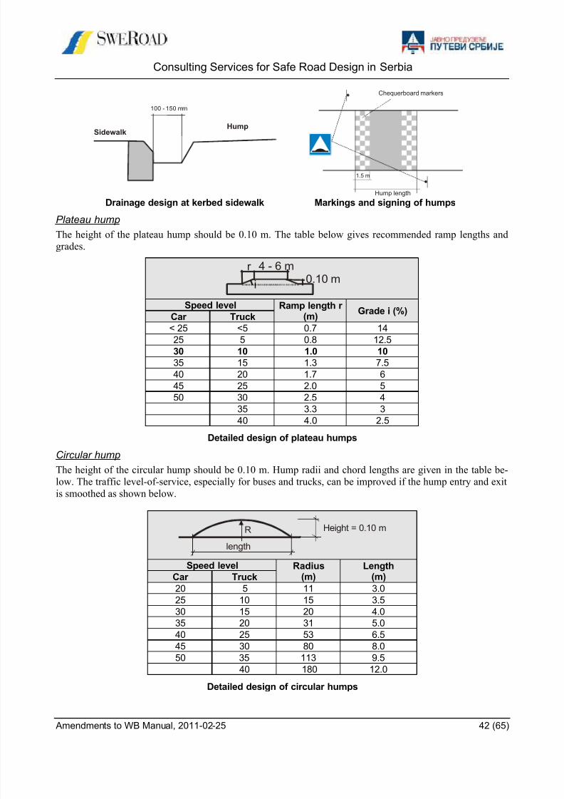
8/9/2019 safe_road_design_manual_amendments_to_wb.pdf
http://slidepdf.com/reader/full/saferoaddesignmanualamendmentstowbpdf 42/65
Consulting Services for Safe Road Design in Serbia
Amendments to WB Manual, 2011-02-25 42 (65)
Drainage design at kerbed sidewalk Markings and signing of humps
Plateau hump
The height of the plateau hump should be 0.10 m. The table below gives recommended ramp lengths and
grades.
Speed level Ramp length r(m)
Grade i (%)Car Truck
< 25 <5 0.7 14
25 5 0.8 12.5
30 10 1.0 10
35 15 1.3 7.5
40 20 1.7 6
45 25 2.0 5
50 30 2.5 4
35 3.3 3
40 4.0 2.5
Detailed design of plateau humps
Circular hump
The height of the circular hump should be 0.10 m. Hump radii and chord lengths are given in the table be-
low. The traffic level-of-service, especially for buses and trucks, can be improved if the hump entry and exit
is smoothed as shown below.
Speed level Radius(m)
Length(m)Car Truck
20 5 11 3.0
25 10 15 3.5
30 15 20 4.0
35 20 31 5.0
40 25 53 6.5
45 30 80 8.0
50 35 113 9.5
40 180 12.0
Detailed design of circular humps
100 - 150 mm
HumpSidewalk
Hump length
Chequerboard markers
1.5 m
i
r
0.10 m
4 - 6 m
length
Height = 0.10 mR
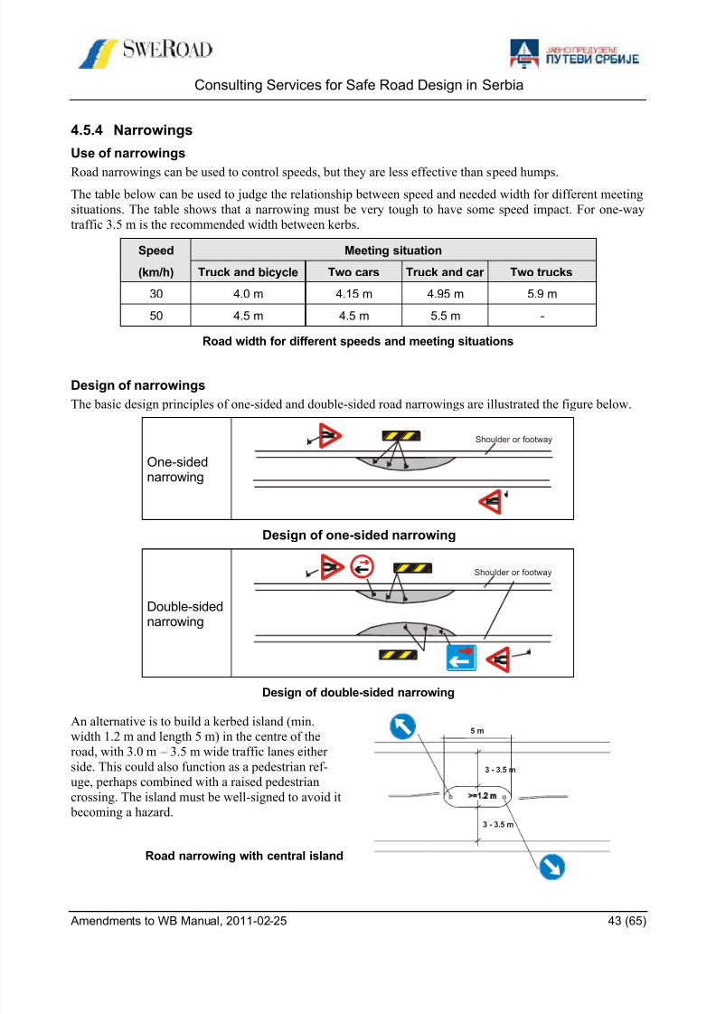
8/9/2019 safe_road_design_manual_amendments_to_wb.pdf
http://slidepdf.com/reader/full/saferoaddesignmanualamendmentstowbpdf 43/65
Consulting Services for Safe Road Design in Serbia
Amendments to WB Manual, 2011-02-25 43 (65)
4.5.4 Narrowings
Use of narrowings
Road narrowings can be used to control speeds, but they are less effective than speed humps.The table below can be used to judge the relationship between speed and needed width for different meeting
situations. The table shows that a narrowing must be very tough to have some speed impact. For one-way
traffic 3.5 m is the recommended width between kerbs.
Speed Meeting situation
(km/h) Truck and bicycle Two cars Truck and car Two trucks
30 4.0 m 4.15 m 4.95 m 5.9 m
50 4.5 m 4.5 m 5.5 m -
Road width for different speeds and meeting situations
Design of narrowings
The basic design principles of one-sided and double-sided road narrowings are illustrated the figure below.
One-sidednarrowing
Design of one-sided narrowing
Double-sidednarrowing
Design of double-sided narrowing
An alternative is to build a kerbed island (min.
width 1.2 m and length 5 m) in the centre of the
road, with 3.0 m – 3.5 m wide traffic lanes either
side. This could also function as a pedestrian ref-
uge, perhaps combined with a raised pedestrian
crossing. The island must be well-signed to avoid it
becoming a hazard.
Road narrowing with central island
Shoulder or footway
Shoulder or footway
3 - 3.5 m
5 m
3 - 3.5 m

8/9/2019 safe_road_design_manual_amendments_to_wb.pdf
http://slidepdf.com/reader/full/saferoaddesignmanualamendmentstowbpdf 44/65
Consulting Services for Safe Road Design in Serbia
Amendments to WB Manual, 2011-02-25 44 (65)
5 INTERSECTIONS
5.1 Intersection types
5.1.1 Proposed intersection typesThis Manual covers only at-grade intersections. At-grade intersections can be classified into two main inter-
section categories depending on the form of control used. For each category, there are a number of intersec-
tion types .
Intersection cate-gory
Traffic control
Intersection types
Major road Minor road
Priority intersection PriorityStop or give way
sign
A Unchannelised T-intersectionB Partly Channelised T-intersectionC Channelised T-intersection
Control intersection Traffic signals or give way signD RoundaboutE Signalised intersection
Classification of at-grade intersections
5.1.2 Priority intersections
Priority intersections will be adequate in most rural situations. This Manual gives advice on the design of
three types of T-intersection:
Unchannelised Partly channelised Channelised
Typical design of T-intersections
Unchannelised T-intersection (A)
The unchannelised design is suitable for intersections where there is a very small amount of turning traf-
fic. It is the simplest design and has no traffic islands.
Partly Channelised T-intersection (B)
The partly channelised design is for intersections with a moderate volume of turning traffic. It has a traffic
island in the minor road arm. In urban areas, the traffic island would normally be kerbed in order to provide a
refuge for pedestrians crossing the road.

8/9/2019 safe_road_design_manual_amendments_to_wb.pdf
http://slidepdf.com/reader/full/saferoaddesignmanualamendmentstowbpdf 45/65
Consulting Services for Safe Road Design in Serbia
Amendments to WB Manual, 2011-02-25 45 (65)
Channelised T-intersection (C)
The fully channelised design is for intersections with a high volume of turning traffic or high – speeds. It
has traffic islands in both the minor road and the main road.
Four-leg priority intersections (crossroads) must not be used. It has a very high number of conflict points, and has a much higher accident risk than any other kind of intersection. Existing crossroads should,
where possible, be converted to a staggered intersection, or roundabout, or be controlled by traffic signals.
5.1.3 Control intersections
Control intersections are mostly used in towns and trading centres. However, roundabouts can be used in
rural areas in intersections between major roads or other intersections with high traffic volumes. There are
two types of control intersections:
Roundabout (D)
Roundabouts are controlled by the rule that all entry traffic must give way to circulating traffic. The ratio of
minor road incoming traffic to the total incoming traffic should preferably be at least 10 to 15%. Rounda- bouts can be of normal size, i.e. with central island radius 10 m or more, or small size, i.e. with central island
radius less than 10 m.
Signalized intersection (E)
Signalised intersections have conflicts separated by traffic signals. No conflicts are allowed between straight
through traffic movements.
Roundabout Signalised intersection
Alternative design of roundabout (normally used at diamond interchanges)
Typical designs for control intersections

8/9/2019 safe_road_design_manual_amendments_to_wb.pdf
http://slidepdf.com/reader/full/saferoaddesignmanualamendmentstowbpdf 46/65
Consulting Services for Safe Road Design in Serbia
Amendments to WB Manual, 2011-02-25 46 (65)
5.2 Selection of intersection type
This section presents an example from Sweden to show principles for the selection of intersection type. It
should not be used in Serbia without adaptation to Serbian conditions.
5.2.1 General
These selection guidelines mainly deal with traffic safety. Other important impacts such as capacity / road
user costs, environmental issues, investment and maintenance costs should also be taken into consideration.
Capacity, delays, queue lengths, road user costs and also exhaust emissions could be estimated using stand-
ard software such as Oscady, Picady and Arcady (UK) SIDRA (Australia) or Capcal (Sweden) but they have
not been calibrated for Serbian conditions, so they could give misleading results. Some traffic flow threshold
values for capacity are given in figure 6.6.
The safety requirement for intersections can be defined as an interval where the expected number of acci-
dents should not exceed a desired level and must not exceed a maximum level. If the expected number of
accidents does not exceed the desired level, a priority intersection should be selected. If the number exceeds
the maximum level, a control intersection should be selected. Between the two defined levels, a control inter-
section should be considered. The traffic flow threshold values presented in the following Figures 6.5 and 6.7
are based on this concept using general European traffic safety research results on the relationship between
speed and incoming traffic flows on the major and minor road.
The selection is divided into two steps; selection of intersection category (priority or control) and selection of
intersection type. It is based on the following assumptions:
Priority intersections can be safe and give sufficient capacity for certain traffic volumes and speed lim-
its
If a priority intersection is not sufficient for safety and capacity, the major road traffic must also be
controlled.
Depending on location, traffic conditions and speed limits, different types of priority or control intersec-
tion should be selected.
5.2.2 Selection of intersection category
Safety
The selection of intersection category should mainly be based on safety. The selection can be made by using
diagrams with the relationships between the safety levels and the average annual daily approaching traffic
volumes (AADT in veh/day) based on accident statistics. The diagrams shown in below are for T-
intersections on 2-lane roads with 50, 80 and 100 km/h speed limit. The diagrams are, as already stated,
based on general European experience on relationships between speed, safety and traffic flows. They are
judged reasonable to be used in Serbia until sufficient local research is available.
2000
4000
6000
5000 10000
Minor road approaching AADT, Q3 veh/day
Major road approaching AADT, Q1+Q2 veh/day
Select contro l
intersection
Select priori ty
intersection
Consider contro l
intersection
50 km/hQ1
Q2
Q3
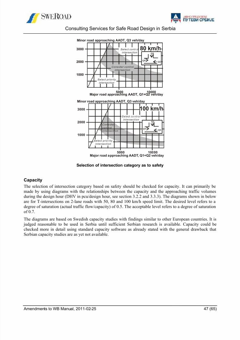
8/9/2019 safe_road_design_manual_amendments_to_wb.pdf
http://slidepdf.com/reader/full/saferoaddesignmanualamendmentstowbpdf 47/65
Consulting Services for Safe Road Design in Serbia
Amendments to WB Manual, 2011-02-25 47 (65)
Selection of intersection category as to safety
Capacity
The selection of intersection category based on safety should be checked for capacity. It can primarily be
made by using diagrams with the relationships between the capacity and the approaching traffic volumes
during the design hour (DHV in pcu/design hour, see section 3.2.2 and 3.3.3). The diagrams shown in below
are for T-intersections on 2-lane roads with 50, 80 and 100 km/h speed limit. The desired level refers to a
degree of saturation (actual traffic flow/capacity) of 0.5. The acceptable level refers to a degree of saturation
of 0.7.
The diagrams are based on Swedish capacity studies with findings similar to other European countries. It is
judged reasonable to be used in Serbia until sufficient Serbian research is available. Capacity could be
checked more in detail using standard capacity software as already stated with the general drawback that
Serbian capacity studies are as yet not available.
Minor road approaching AADT, Q3 veh/day
Major road approaching AADT, Q1+Q2 veh/day
1000
2000
3000
5000 10000
Select contr ol
intersection
Select priori ty
intersection
Consider contro l
intersection
80 km/h
Q1Q2
Q3
Minor road approaching AADT, Q3 veh/day
Major road approaching AADT, Q1+Q2 veh/day
1000
2000
3000
5000 10000
Select co ntro l
in tersect ion
Select prio ri ty
in tersect ion
Consider
con t ro l
in tersect ion
100 km/h
Q1Q2
Q3

8/9/2019 safe_road_design_manual_amendments_to_wb.pdf
http://slidepdf.com/reader/full/saferoaddesignmanualamendmentstowbpdf 48/65
Consulting Services for Safe Road Design in Serbia
Amendments to WB Manual, 2011-02-25 48 (65)
Selection of intersection category as to capacity
Desired
Acceptable
50km/h400
500 1000 1500
200
00
Control or grade-separated intersection needed
Minor road approaching DHV, Q3 pcu/design hour Minor road approaching DHV, Q3 pcu/design hour
Major road approaching DHV,Q1+Q2 pcu/design hour
Q1Q2
Q3
Desired
Acceptable
80km/h400
500 1000 1500
200
0
0
Control or grade-separated intersection needed
Minor road approaching DHV, Q3 pcu/design hour
Major road approaching DHV,Q1+Q2 pcu/design hour
Q1Q2
Q3
Desired
Acceptable Control or grade-separated intersection needed
100km/h400
500 1000 1500
200
00
Minor road approaching DHV, Q3 pcu/design hour
Major road approaching DHV,Q1+Q2 pcu/design hour
Q1Q2
Q3

8/9/2019 safe_road_design_manual_amendments_to_wb.pdf
http://slidepdf.com/reader/full/saferoaddesignmanualamendmentstowbpdf 49/65
Consulting Services for Safe Road Design in Serbia
Amendments to WB Manual, 2011-02-25 49 (65)
5.2.3 Selection of intersection type
Priority intersections
The selection of priority intersection type should mainly be based on safety. The selection can be made by
using diagrams with the relationships between the safety levels and the average annual daily approachingtraffic volumes (AADT in veh/day, see section 3.2.2) based on accident statistics. The diagrams shown in
below are for T-intersections on 2-lane roads with 50, 80 and 100 km/h speed limit. Crossroads should be
avoided. The number of right turners should obviously also impact the decision.
The diagrams are based on general European findings on safety effects of right turn lanes. It is judged rea-
sonable to be used in Serbia until sufficient Serbian statistics are available. Note however they are only a
starting point for determining the most appropriate form of intersection.
Selection of priority intersection type as to safety
Partly channelised should normally be used if needed to facilitate pedestrian crossings and also if the minor
road island is needed to improve the visibility of the intersection.
2000
4000
6000
5000 10000
Select unchannel ised
or partly channel ised
T-intersection
Select channel ised
T-intersection
50 km/h
500
1000
1500
5000 10000
Select channel ised
T-intersection
Select unchannel ised
or partly chan nel ised T-intersection
100 km/h
1000
2000
3000
5000 10000
Select channel ised
T-intersection
Select unchannel ised
or partly channel ised
T-intersection
80 km/h
Minor road approaching AADT, Q3 veh/day
Minor road approaching AADT, Q3 veh/day
Minor road approaching AADT, Q3 veh/day
Major road approaching AADT, Q1+Q2 veh/day
Major road approaching AADT, Q1+Q2 veh/day
Major road approaching AADT, Q1+Q2 veh/day
Q1Q2
Q3
Q1Q2
Q3
Q1Q2
Q3
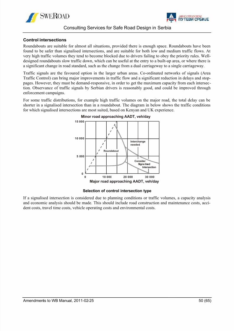
8/9/2019 safe_road_design_manual_amendments_to_wb.pdf
http://slidepdf.com/reader/full/saferoaddesignmanualamendmentstowbpdf 50/65
Consulting Services for Safe Road Design in Serbia
Amendments to WB Manual, 2011-02-25 50 (65)
Control intersections
Roundabouts are suitable for almost all situations, provided there is enough space. Roundabouts have been
found to be safer than signalised intersections, and are suitable for both low and medium traffic flows. At
very high traffic volumes they tend to become blocked due to drivers failing to obey the priority rules. Well-designed roundabouts slow traffic down, which can be useful at the entry to a built-up area, or where there is
a significant change in road standard, such as the change from a dual carriageway to a single carriageway.
Traffic signals are the favoured option in the larger urban areas. Co-ordinated networks of signals (Area
Traffic Control) can bring major improvements in traffic flow and a significant reduction in delays and stop-
pages. However, they must be demand-responsive, in order to get the maximum capacity from each intersec-
tion. Observance of traffic signals by Serbian drivers is reasonably good, and could be improved through
enforcement campaigns.
For some traffic distributions, for example high traffic volumes on the major road, the total delay can be
shorter in a signalised intersection than in a roundabout. The diagram in below shows the traffic conditions
for which signalised intersections are most suited, based on Kenyan and UK experience.
Selection of control intersection type
If a signalised intersection is considered due to planning conditions or traffic volumes, a capacity analysis
and economic analysis should be made. This should include road construction and maintenance costs, acci-
dent costs, travel time costs, vehicle operating costs and environmental costs.
Roundabout
Interchange
needed
Consider Signa lised
Intersection
10 00000
5 000
10 000
15 000
20 000 30 000
Minor road approaching AADT, veh/day
Major road approaching AADT, veh/day

8/9/2019 safe_road_design_manual_amendments_to_wb.pdf
http://slidepdf.com/reader/full/saferoaddesignmanualamendmentstowbpdf 51/65
Consulting Services for Safe Road Design in Serbia
Amendments to WB Manual, 2011-02-25 51 (65)
6 ROADSIDE FACILITIES
6.1 Bus stops
6.1.1 Bus stop typesOn rural roads there are generally four types of bus stops to be used.
1. Separated bus stop
2. Bus stop in the traffic lane
3. Bus stop on the shoulder
4. Bus lay-by
In rural areas, especially on high speed roads, it is important that buses entering or leaving the bus stop not
obstruct other road users. Consequently, the type of bus stop to be selected depends primarily on the traffic
volume and the number of buses using the bus stop. Other factors influencing the selection are the speed
limit, visibility, vulnerable road users, the number of lanes and shoulder width.
6.1.2 Design of Bus stops
The figures in this section show recommended design from the Swedish guidelines.
Separated bus stop
Separated bus stop should be used on high volume roads, especially on roads with more than two lanes. It
should be separated from the travelled way by a fence, a traffic island or a grass strip. Acceleration and de-
celeration mainly take place on the entry and exit and the obstruction to other vehicles is minimized.
Speedlimit,km/h
70 90 110
LI, m 55 85 115
LII, m 0 60 110
v = shoulder width
p = platform length
Separated bus stop
Lay-by
Separated
Traffic lane
Shoulder
Buses per hour
Average daily traffic
ExitEntry

8/9/2019 safe_road_design_manual_amendments_to_wb.pdf
http://slidepdf.com/reader/full/saferoaddesignmanualamendmentstowbpdf 52/65
Consulting Services for Safe Road Design in Serbia
Amendments to WB Manual, 2011-02-25 52 (65)
Bus stop in the traffic lane
Bus stop in the traffic lane can be used on low traffic two lane roads without or with narrow shoulders. There
is generally no platform for the passengers. Busses at the bus stop lane block and obstruct the sight for all the
vehicles behind.
Bus stop in traffic lane
Bus stop on the shoulder
Bus stop on the shoulder can be used where the shoulder is at least 2 meters wide. There is generally no plat-
form for the passengers
Busses at the bus stop lane block and obstruct the sight for vehicles using the shoulder, for example cyclists.
Bus stop on shoulder
Bus lay-byA bus lay-by outside the travelled way is the preferred bus stop on rural roads with high traffic volumes.
There is generally no platform for the passengers
Busses at the bus stop do not generally block or obstruct the sight for vehicles behind.
Bus lay-by on roads with speed limit < 80 km/h
Bus lay-by on roads with speed limit ≥80 km/h
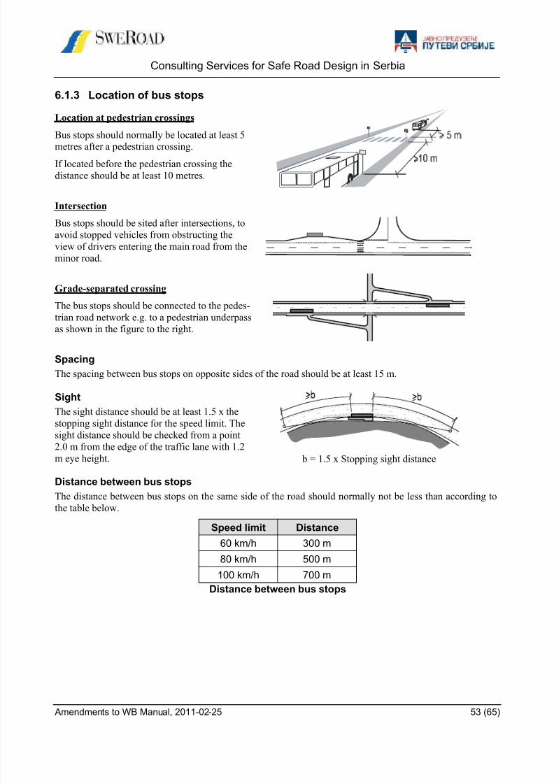
8/9/2019 safe_road_design_manual_amendments_to_wb.pdf
http://slidepdf.com/reader/full/saferoaddesignmanualamendmentstowbpdf 53/65
Consulting Services for Safe Road Design in Serbia
Amendments to WB Manual, 2011-02-25 53 (65)
6.1.3 Location of bus stops
Location at pedestrian crossings
Bus stops should normally be located at least 5metres after a pedestrian crossing.
If located before the pedestrian crossing the
distance should be at least 10 metres.
Intersection
Bus stops should be sited after intersections, to
avoid stopped vehicles from obstructing the
view of drivers entering the main road from the
minor road.
Grade-separated crossing
The bus stops should be connected to the pedes-
trian road network e.g. to a pedestrian underpass
as shown in the figure to the right.
Spacing
The spacing between bus stops on opposite sides of the road should be at least 15 m.
Sight
The sight distance should be at least 1.5 x thestopping sight distance for the speed limit. The
sight distance should be checked from a point
2.0 m from the edge of the traffic lane with 1.2
m eye height. b = 1.5 x Stopping sight distance
Distance between bus stops
The distance between bus stops on the same side of the road should normally not be less than according to
the table below.
Distance between bus stops
Speed limit Distance
60 km/h 300 m
80 km/h 500 m
100 km/h 700 m

8/9/2019 safe_road_design_manual_amendments_to_wb.pdf
http://slidepdf.com/reader/full/saferoaddesignmanualamendmentstowbpdf 54/65
Consulting Services for Safe Road Design in Serbia
Amendments to WB Manual, 2011-02-25 54 (65)
6.2 Lay-bys
6.2.1 The use of lay-bys
A lay-by is an area adjacent to the road for temporary parking of vehicles. Lay-bys should be used for shortrests etc and/or information to road users. Adjoining the lay-by there should be an area for rest and recrea-
tion, preferably equipped with seats and tables.
A lay-by for rest and/or information should normally not be used as a bus-stop. For lay-bys designed as bus-
stops see the previous chapter!
6.2.2 Location
Lay-bys can be used on all roads except motorways. They should normally be used for traffic in one direc-
tion only. To avoid median crossings they should be located in pairs. On roads without medians, the lay-bys
should be placed with at least 10 meters displacement with the right hand lay-by first.
Lay-bys in pairs
Considering the road users disposition to use lay-bys the driving time between two facilities should be about
20 minutes. On roads with a high proportion long distant traffic the distance can be extended to about 30
minutes driving time. That means that the distance can vary from around 20 km (normal roads with 60 km/
speed limit) to around 50 km (national roads with 100 km sped limit).
6.2.3 Design
All types of vehicles should be able to use the lay-bys. Consequently, they should be designed for all normal
vehicles including buses and trucks. The figure below shows a suitable design for all normal vehicles.
Shoulderwidth
WidthD
ExitL1
ParkingL2
EntryL3
< 2 m 4.5 m 15 m ≥ 20 m 25 m
≥ 2 m 6 m 20 m ≥ 20 m 35 m
Design of lay-bys

8/9/2019 safe_road_design_manual_amendments_to_wb.pdf
http://slidepdf.com/reader/full/saferoaddesignmanualamendmentstowbpdf 55/65
Consulting Services for Safe Road Design in Serbia
Amendments to WB Manual, 2011-02-25 55 (65)
6.3 Rest areas
A rest area can be used for traffic in one or two directions. The figure below shows a typical design of a rest
area used for traffic in one direction.
Typical design of a rest area for traffic in one direction
If the rest area is used by traffic in both directions the entry and the exit should designed as normal T-
intersections
Voitures touristiques
Toilette
Camion (24 m)
Poubelle Poubelle
Tables
Voitures touristiques
Toilette
Camion (24 m)
Poubelle Poubelle
Tables
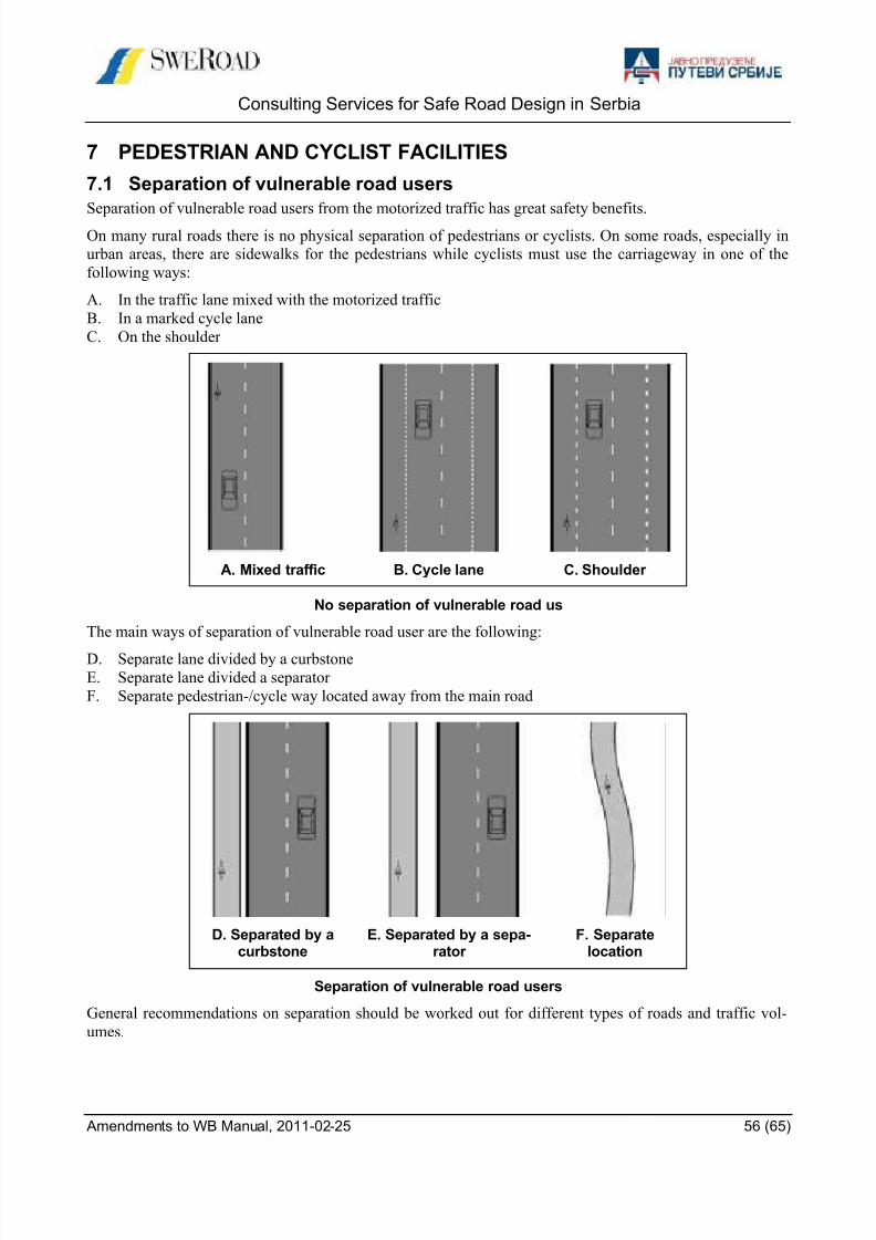
8/9/2019 safe_road_design_manual_amendments_to_wb.pdf
http://slidepdf.com/reader/full/saferoaddesignmanualamendmentstowbpdf 56/65
Consulting Services for Safe Road Design in Serbia
Amendments to WB Manual, 2011-02-25 56 (65)
7 PEDESTRIAN AND CYCLIST FACILITIES
7.1 Separation of vulnerable road users
Separation of vulnerable road users from the motorized traffic has great safety benefits.
On many rural roads there is no physical separation of pedestrians or cyclists. On some roads, especially in
urban areas, there are sidewalks for the pedestrians while cyclists must use the carriageway in one of the
following ways:
A. In the traffic lane mixed with the motorized traffic
B. In a marked cycle lane
C. On the shoulder
A. Mixed traffic B. Cycle lane C. Shoulder
No separation of vulnerable road us
The main ways of separation of vulnerable road user are the following:
D. Separate lane divided by a curbstone
E. Separate lane divided a separator
F. Separate pedestrian-/cycle way located away from the main road
D. Separated by acurbstone
E. Separated by a sepa-rator
F. Separatelocation
Separation of vulnerable road users
General recommendations on separation should be worked out for different types of roads and traffic vol-
umes.

8/9/2019 safe_road_design_manual_amendments_to_wb.pdf
http://slidepdf.com/reader/full/saferoaddesignmanualamendmentstowbpdf 57/65
Consulting Services for Safe Road Design in Serbia
Amendments to WB Manual, 2011-02-25 57 (65)
7.2 Pedestrian crossings
7.2.1 Background and safety considerations
It is difficult to set down criteria for the provision of pedestrian crossing facilities. Factors to take into ac-
count include:
the volume of pedestrians crossing the road
the speed of the traffic
the width of the road
if there are a lot of children crossing
if there are significant numbers of disabled pedestrians
7.2.2 Pedestrian bridges and tunnels
Location
Bridges and tunnels for pedestrians and cyclists should be used on high-speed and / or high-volume roads.On normal roads bridges and tunnels are not generally recommended, because they are inconvenient to use,
and have a number of other problems, including crime, vandalism, and maintenance. However, they are ap-
propriate where the terrain is such that pedestrians can use the bridge or tunnel without having to climb or
descend. Thus, the provision of a pedestrian bridge or tunnel depends on:
The possibilities to locate and design the bridge in a way it will be used
The costs for the bridge in relation to the number of pedestrians
The traffic volume
For example, if the terrain is favorable a bridge should be provided even if the traffic volume and/or the
number of pedestrians are low. On the other hand, if the traffic volume and/or the number of pedestrians are
very high a pedestrian bridge should always be built.
Whenever possible the bridge or tunnel should be in line with the normal path that pedestrians and cyclists
take when crossing the road. If they have to diverge from their direct route they will be discouraged from
using the facility. Barriers can be used to try and force them to use the facility if the detour not is unreasona-
ble.
Dimensions
Bridges should normally be 2-3 meters wide. The width and height of tunnels depend on the length of the
tunnel. Recommended minimum dimensions for tunnels are given in the table below.
Type of tunnelWidth
(m)Height
(m)
Narrow (short) 2.3 2.3
Standard 3.3 2.6
Wide (long) 5.0 2.6
Minimum tunnel dimensions
Accesses
Ideally, there should be a both stairs and ramps. Ramps should not normally be steeper than 5% and should
have a non-slip surface. If there are many disabled persons the ramp should not be steeper than 3%.
To avoid unreasonable detours steeper ramps can be accepted.

8/9/2019 safe_road_design_manual_amendments_to_wb.pdf
http://slidepdf.com/reader/full/saferoaddesignmanualamendmentstowbpdf 58/65
Consulting Services for Safe Road Design in Serbia
Amendments to WB Manual, 2011-02-25 58 (65)
7.2.3 At-grade crossings (Zebra crossing)
General
If there is no bridge or tunnel, zebra crossings should be provided to give the pedestrians a reasonable safe
way to cross the road. However, zebra-crossings should not be used on roads with a speed limit over 50 km/hsince they give a “false sense of safety”.
Crossings on a separated highway should be staggered with short pedestrian road in the median parallel to
the roads. The purpose is to let pedestrians face the traffic before crossing the road, as shown in the figure
below.
Detailed Design
General
Ramp entry is recommended to the crossing if there is a raised walkway along the road, see figure below.
Alternative material at crossing
Ramp to ease crossing forwheel chairs
Kerb for directional advice
Recommended ramp entry to pedestrian crossing
The minimum width of the median island is decided by the sign width chosen, which is normally 0.6 m at
intersections m and 0.9 m at single pedestrian crossings. The additional margin would be minimum 2*0.3 m.
The minimum width of the markings should be 2.5 m. Wider crossings could be needed at large pedestrianflows, see Highway Capacity Manual.
The island could be made wider to get the desired conflict zone width, which is recommended not to be
longer than preferably 4 m and maximum 5 m to avoid the possibility of overtaking. This means that this
type of crossing is not recommended on multilane highways.
The kerb height is recommended to be 0.1 m. The minimum length of the island is 1 m and the minimum
radius 0.5 m.
Pedestrian could be directed to the crossing by use of rails.
The geometric measures could be strengthened with humps. These could be applied as Watt humps upstream
the crossing. Another option is to elevate the crossing itself by use of a plateau hump. Hump design is de-
scribed more in detail in a separate section.
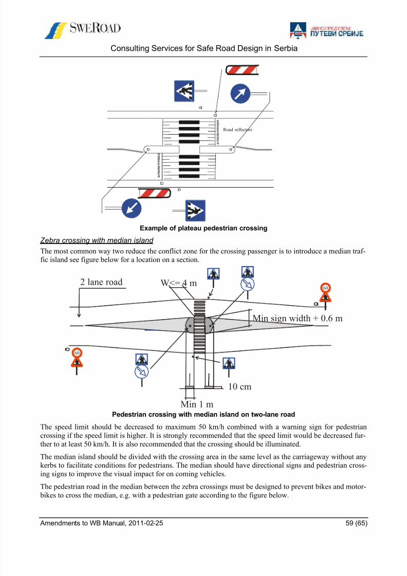
8/9/2019 safe_road_design_manual_amendments_to_wb.pdf
http://slidepdf.com/reader/full/saferoaddesignmanualamendmentstowbpdf 59/65
Consulting Services for Safe Road Design in Serbia
Amendments to WB Manual, 2011-02-25 59 (65)
Road reflectors
Example of plateau pedestrian crossing
Zebra crossing with median island
The most common way two reduce the conflict zone for the crossing passenger is to introduce a median traf-
fic island see figure below for a location on a section.
2 lane road W<= 4 m
10 cm
Min 1 m
Min sign width + 0.6 m
60
60
Pedestrian crossing with median island on two-lane road
The speed limit should be decreased to maximum 50 km/h combined with a warning sign for pedestrian
crossing if the speed limit is higher. It is strongly recommended that the speed limit would be decreased fur-
ther to at least 50 km/h. It is also recommended that the crossing should be illuminated.
The median island should be divided with the crossing area in the same level as the carriageway without any
kerbs to facilitate conditions for pedestrians. The median should have directional signs and pedestrian cross-
ing signs to improve the visual impact for on coming vehicles.
The pedestrian road in the median between the zebra crossings must be designed to prevent bikes and motor-
bikes to cross the median, e.g. with a pedestrian gate according to the figure below.
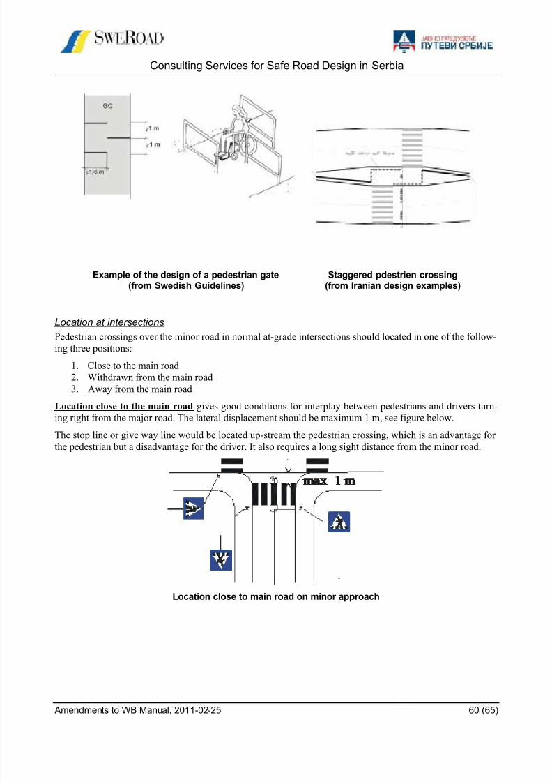
8/9/2019 safe_road_design_manual_amendments_to_wb.pdf
http://slidepdf.com/reader/full/saferoaddesignmanualamendmentstowbpdf 60/65
Consulting Services for Safe Road Design in Serbia
Amendments to WB Manual, 2011-02-25 60 (65)
Example of the design of a pedestrian gate(from Swedish Guidelines)
Staggered pdestrien crossing(from Iranian design examples)
Location at intersections
Pedestrian crossings over the minor road in normal at-grade intersections should located in one of the follow-
ing three positions:
1. Close to the main road
2. Withdrawn from the main road
3. Away from the main road
Location close to the main road gives good conditions for interplay between pedestrians and drivers turn-ing right from the major road. The lateral displacement should be maximum 1 m, see figure below.
The stop line or give way line would be located up-stream the pedestrian crossing, which is an advantage for
the pedestrian but a disadvantage for the driver. It also requires a long sight distance from the minor road.
Location close to main road on minor approach

8/9/2019 safe_road_design_manual_amendments_to_wb.pdf
http://slidepdf.com/reader/full/saferoaddesignmanualamendmentstowbpdf 61/65
Consulting Services for Safe Road Design in Serbia
Amendments to WB Manual, 2011-02-25 61 (65)
Location withdrawn from the major road enough to ensure a right-angled conflict between a right turning
passenger car and a pedestrian crosser and also to give storage for one passenger car between the stop line
and the pedestrian crossing. The lateral displacement should approximately 6 m, see figure below. Locations
in the interval 1 to 6 m deteriorate possibilities for eye-contact between the car driver and the biker. The
driver might even have dead angles due to back mirror location on his car.
This solution gives better level-of-service for cars from the minor road, to catch gaps in the major road due
to the better overview. Pedestrian have to take a detour. Many safety researchers claim that the first solution
is better from a traffic safety point of view.
Location 6 m from intersection on minor approach
The intersection curve design is of outmost importance for the traffic safety of pedestrian crossings at inter-
sections. Wide tapers and large radii to facilitate high speeds and to accommodate large trucks are obviously
hazardous for traffic safety. Speeds will obviously increase. Sight angles between pedestrians and drivers
will deteriorate and conflict zones will grow, see figure below. Right turn lanes are not recommended for the
same reason.
Impact of intersection curve design
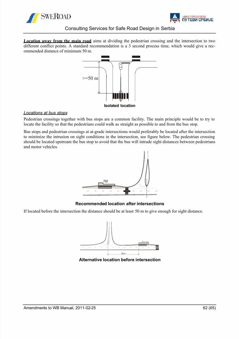
8/9/2019 safe_road_design_manual_amendments_to_wb.pdf
http://slidepdf.com/reader/full/saferoaddesignmanualamendmentstowbpdf 62/65
Consulting Services for Safe Road Design in Serbia
Amendments to WB Manual, 2011-02-25 62 (65)
Location away from the main road aims at dividing the pedestrian crossing and the intersection to two
different conflict points. A standard recommendation is a 3 second process time, which would give a rec-
ommended distance of minimum 50 m.
>=50 m
Isolated location
Locations at bus stops
Pedestrian crossings together with bus stops are a common facility. The main principle would be to try tolocate the facility so that the pedestrians could walk as straight as possible to and from the bus stop.
Bus stops and pedestrian crossings at at-grade intersections would preferably be located after the intersection
to minimize the intrusion on sight conditions in the intersection, see figure below. The pedestrian crossing
should be located upstream the bus stop to avoid that the bus will intrude sight distances between pedestrians
and motor vehicles.
Recommended location after intersections
If located before the intersection the distance should be at least 50 m to give enough for sight distance.
Bus stop
50 m
Alternative location before intersection
Hpl
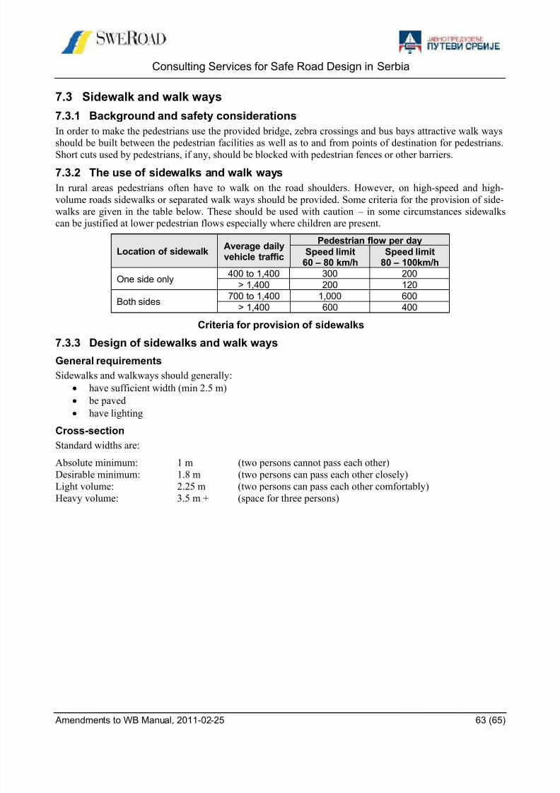
8/9/2019 safe_road_design_manual_amendments_to_wb.pdf
http://slidepdf.com/reader/full/saferoaddesignmanualamendmentstowbpdf 63/65
Consulting Services for Safe Road Design in Serbia
Amendments to WB Manual, 2011-02-25 63 (65)
7.3 Sidewalk and walk ways
7.3.1 Background and safety considerations
In order to make the pedestrians use the provided bridge, zebra crossings and bus bays attractive walk ways
should be built between the pedestrian facilities as well as to and from points of destination for pedestrians.
Short cuts used by pedestrians, if any, should be blocked with pedestrian fences or other barriers.
7.3.2 The use of sidewalks and walk ways
In rural areas pedestrians often have to walk on the road shoulders. However, on high-speed and high-
volume roads sidewalks or separated walk ways should be provided. Some criteria for the provision of side-
walks are given in the table below. These should be used with caution – in some circumstances sidewalks
can be justified at lower pedestrian flows especially where children are present.
Location of sidewalkAverage dailyvehicle traffic
Pedestrian flow per day
Speed limit60 – 80 km/h
Speed limit80 – 100km/h
One side only 400 to 1,400 300 200> 1,400 200 120
Both sides700 to 1,400 1,000 600
> 1,400 600 400
Criteria for provision of sidewalks
7.3.3 Design of sidewalks and walk ways
General requirements
Sidewalks and walkways should generally:
have sufficient width (min 2.5 m)
be paved
have lightingCross-section
Standard widths are:
Absolute minimum: 1 m (two persons cannot pass each other)
Desirable minimum: 1.8 m (two persons can pass each other closely)
Light volume: 2.25 m (two persons can pass each other comfortably)
Heavy volume: 3.5 m + (space for three persons)
8/9/2019 safe_road_design_manual_amendments_to_wb.pdf
http://slidepdf.com/reader/full/saferoaddesignmanualamendmentstowbpdf 64/65
Consulting Services for Safe Road Design in Serbia
Amendments to WB Manual, 2011-02-25 64 (65)
8 SIGNS AND MARKINGS
Introduction
Signs and markings can provide important information to improve road safety. They regulate, warn and
guide road users. By letting people know what to expect, chances are greater that they will react and behave
appropriately. Signs and markings need to be applied in a consistent way, to be placed at logical locations,
and be easy to understand and visible.
This also means that underlying traffic regulations such as local speed limits need to be established on clear
and consistent principles. The visibility of signs and markings needs to be checked regularly to avoid them
being hidden by overgrown trees or blurred by sunlight. The use of retro-reflective material is needed to
ensure night-time visibility
Road side signs must be used sparsely. Road users are only able to process a limited amount of information
at a time. Too many signs at a particular spot may confuse and distract road users rather than help them.
Too many signs may also result in non-compliance and disrespect.
How effective and costly is it? Research from different countries has shown that the number of injury crashescan be reduced by over 30 % by shoulder rumble strips and by over 10 % by centreline rumble strips. Esti-
mations of costs vary largely. Cost-benefit analyses from Norway and USA have estimated that the benefits
exceed the costs by factor between ca 3 and 180.
(From: Best practices in road safety, Handbook for measures at the country level, EU 2010)
8.1 General requirements
8.1.1 Traffic Signs
Clear and efficient signing is an essential part of the road system, and a road with poor signing or with badly
maintained signs is not functioning well. Road users depend on signing for information and guidance, and
road authorities depend on signing for traffic control and regulation, and for road safety.
The key requirements for each traffic sign are that it should:
meet a need
command attention
be legible
convey a simple, clear meaning at a glance
be placed so as to give road users time to respond
command respect
Signs must only be used where there is a clear need for them. The incorrect or unnecessary use of a sign an-
noys drivers, and when this happens frequently, drivers lose respect for the sign, and it becomes ineffective
in situations where it is really needed. For the same reason, avoid using signs which impose a restriction
which will be unpopular and difficult to enforce. Drivers will stop taking signs seriously when they see oth-ers ignoring them without being punished.
Using standard signs assists in their quick recognition, as does uniformity of shape, colour and lettering for
each type. To obtain the full benefits of standardisation, the signs must be used in a consistent manner.
It is important that the message is presented in a simple way. The new signs make a great use of pictorial
symbols, as these are more effective than words, and can be understood by those who cannot read. Signs
with words should be used only where there is no alternative.
Signs must have sufficient impact to be noticed by drivers. This has been taken into account in the design of
the signs, but the size and siting of the sign are also relevant. For most signs there are several permitted sizes,
and it is largely the speed of the traffic at the site that determines which size is appropriate.
8/9/2019 safe_road_design_manual_amendments_to_wb.pdf
http://slidepdf.com/reader/full/saferoaddesignmanualamendmentstowbpdf 65/65