safety and biological aspects of present techniques of haemodialysis
TRANSCRIPT

Safety and biological aspects of present techniques ofhaemodialysis
Per Jonsson
Umeå 2006
Department of Public Health and Clinical Medicine, MedicineUmeå university, Umeå, Sweden
Dept. of Biomedical Engineering and Informatics, University Hospital of Northern Sweden

5
Umeå University Medical Dissertations
New Series No 1071 * ISSN 0346-6612 * ISBN 91- 7264- 226- 2
From The Departments of:Public Health and Clinical Medicine, Medicine
Umeå University&
Biomedical engineering and informatics, University hospital of northern SwedenS-901 85 Umeå, Sweden
Safety and biological aspects of present techniques of haemodialysis
Per Jonsson
Umeå 2006

6
ISBN 91- 7264- 226- 2© Copyright: Per Jonsson
Departments ofPublic Health and Clinical Medicine, Medicine
Umeå University&
Biomedical engineering and informatics, University hospital of northern SwedenS-901 85 Umeå, Sweden
Printed in Sweden by Print & Media

7
TABLE OF CONTENTSABSTRACT 10LIST OF PAPERS 11LIST OF ABBREVIATIONS 12INTRODUCTION 13Uraemia 13Dialysis 14Need for renal replacement 14The start of experimental dialysis treatment 14Evolution during experimental treatments 15Dialysis as an ordinary clinical treatment in 1960. 16Interest from the industry 16Priorities for treatment: a matter of life and death 16Dialysis today Active renal replacement today can be divided into threeprinciples: 17Access techniques in extracorporeal dialysis or haemodialysis 17Dialysis machine 17The blood system 17Fluid system 18Blood distribution 18Dialysis filter or dialyzer 19Transport over the membrane 20Diffusion principle 20Ultrafiltration principle 20Convection principle 20Haemodialysis (HD) 21Haemofiltration (HF) 21Haemodialfiltration (HDF) 21Safety in biomedical engineering, IEC 601 21Fail life and fail safe 22The frequency of electrical distribution 22Physiological effects of electric current 23Ventricular fibrillation 23Cardiovascular collapse 23Electrical safety in biomedical engineering 24Table 1. Limits for leakage current in IEC 601 25Overall safety issues for dialysis machines (IEC 601-2-16 ) 25Recommendations about acceptable levels of leakage currents and generalstandard vs. collateral standard for haemodialysis machines 25Infusion of air 26Figure 1. Risks of air infusion 27

8
Negative pressure 27Residual air 27Accidents and incidents, air/gas infusion 28Infusion of air 601-2-16 28Is there a safe level of air infusion? 29Microinfusion of air or gas 29Bubbles less than 40µm in diameter 29Bubble/blood interaction 30Endothelial effects 30Effects in capillaries 30Effects in the lungs 30Information and responsibility 30AIMS 31MATERIALS AND METHODS 32Paper I, Dialysis machines 32Electrical safety analyser, Rigel 32Measurement of leakage currents 33Accuracy of the Rigel safety analyser 34Table 2. Estimated accuracy of a reading on the Rigel safety analyser 34Paper II, Blood used 34Priming solution and dialysis fluid 35Electrical safety analyser 36Dialysis system 36Figure 2. In vitro measurement of leakage current 37Statistics 38Addendum to Paper II. In vitro measurement of leakage current through dilutedor concentrated blood during mains on the applied part 38Figure 3. In vitro measurements of leakage current during mains on the appliedpart through diluted or concentrated blood 39Paper III, dialysis system 40Paper III, methods 40Blood sampling and analysis 41Statistics 41Paper IV, material and methods 42Paper V 42RESULTS 50Paper I 43Figure 7. ELn Earth leakage, normal condition 43Figure 8. PCn patient current, normal condition or patient leakage current normalcondition in IEC 601-1 43Figure 9. Patient current, broken ground, PCbGR or patient leakage current singlefault condition in IEC 601-1 44

9
Figure 10. Exc, external current or mains on applied part in IEC 601-1 45Table 7. Earth leakage compared between dialysis machine models. 46Table 8. Patient current, normal condition (PCn) compared between dialysismachine models PCn 47Table 9. Patient Current,,single fault condition compared between dialysismachine models. 48Table 10. Exc, external current or mains on applied part compared betweendialysis machine models. 48Paper II 48Table 11. Leakage current through blood lines in normal condition using saline asa fluid 49Figure 11. Leakage current, blood in bloodlines, single fault condition 50Table 12. Leakage currents through blood lines containing blood during normalcondition 51Figure 12. Leakage current through blood lines containing saline during singlefault condition 52Table 13 Leakage current during the test mains on applied part, flow on/off 54Figure 13 Saline solution in the tubes, mains on applied part 55Figure 14. Leakage current using blood in blood lines and testing mains onapplied part 56Addendum to Paper II. In vitro measurement of leakage current through dilutedor concentrated blood during mains on the applied part 56Figures 15 Correlations albumin concentration vs. leakage current. 57Figures 16 Correlations Hb concentration vs. leakage current. 58Figures 17 Correlations EVF concentration vs. leakage current 59Figure 19. Correlation between blood-volume change 60Paper III 61Figure 20 Change in C3d levels versus time 61Figure 21. Change in variables during series 6 62Figure 22. Correlation between serum albumin and blood haemoblobin duringseries 6 63Paper IV 63Paper V 64DISCUSSION 64Leakage current Paper I - IV 65Distribution of air microbubbles, Paper V 68General conclusions 69ACKNOWLEDGEMENTS 71SAMMANFATTNING PÅ SVENSKA 74REFERENCES 76PAPERS I-V 79
10
ABSTRACTIntroduction: Haemodialysis (HD) is a treatment in which blood from the patient is leadthrough a tubing system into a dialysis device in a extracorporeal circuit. This circuit containssemipermeable membranes (dialyzer). Blood with uraemic toxins flows on one side, and a saltsolution flows on the other side. The salt solution flushes away waste products that have passedthe membrane by diffusion or convection through small pores. From there the blood returns tothe patient through a tubing system that contains an air-trap and a sensor to avoid aircontamination in the blood. Besides air contamination, this treatment is burdened with safetyproblems such as biocompatibility, electrical safety and mechanical safety. The aim of thisthesis was to investigate the safety issues in haemodialysis devices regarding leakage currentand air contamination during standard procedures and simulated fault conditions. Does thedialysis device constitute a risk for the patient?Methods: To determine the extent of leakage current in HD machines, measurements at thefilter-coupling site were performed in vitro according to the safety standard, IEC 601-1, in 5types of dialysis machines. To determine, in vitro, to what extent blood and priming fluidallowed leakage current to pass to the patient, leakage current were also measured in the bloodlines. The blood line was filled with blood from donors or priming fluid in eight different runs.To determine if leakage current could influence biocompatibility, a Fresenius 2008C dialysismachine and 8 hemophan dialyzers were used. Blood lines contained about 400 ml heparinizedblood from each of 8 different donors (in vitro). C3d was measured, in vitro, before start of asimulated dialysis and at 15, 30, 45 and 60 min. during standard dialysis procedure. Then 1.5mA current was switched on and additional samples were drawn at 75 and 90 min. Somepatients need a central dialysis catheter (CDC) for access, placed close to or within the heart.To analyze if leakage current during standard HD would influence the ECG, patients with CDCor with AV-fistula as access were investigated. To analyse if air contamination could occurwithout activating security alarms in the dialysis device, various modes of in vitro dialysissettings were studied, some using a dextran solution to mimic blood viscosity. Besides visualinspection an ultrasound detector for microemboli and microbubbles was also used.Results: The data showed leakage current at the filter coupling site that was significantlyhigher for some devices than for others. The leakage current could pass through blood andpriming fluid. It exceeded the cardiac floating (CF)-safety limit (<50µA) at the top of the CDCusing the test mains on applied part for saline (median 1008µA), for blood (median 610µA)and for a single fault condition using saline (median 68 µA) or blood (47 µA). The leakagecurrent experiments showed that complement activation worsened as the leakage currentincreased. During standard dialysis arrhythmia could occur. Microbubbles were visible at thebottom of the air-trap and bubbles could pass the air-trap towards the venous line withouttriggering the alarm. During recirculation, several ml of air could be collected in anintermediate bag after the venous line. Ultrasound showed the presence of bubbles of sizes 2.5-50 µm as well as more than 50 µm silently passing to the venous line in all runs performed.In conclusion, the data showed that a leakage current in HD devices can be high enough to bea safety risk for the patient. This risk is greater if a single fault arises in the dialysis machine oranother device connected to the same patient, or during mains contact to the patient. Then thecurrent flow may be high enough to cause arrhythmia for the patient, especially when using aCDC. There is also reason for concern that micro bubble transmission may occur withoutinducing an alarm. These factors need to be looked over to improve safety regulations andoptimize HD treatment and service schedules.Key words: Haemodialysis, Safety, Leakage current, Central dialysis catheter, Microbubbles,Microemboli, Air contamination.

11
LIST OF PAPERS
I Jonsson P, Stegmayr BG. Current leakage in hemodialysismachines may be a safety risk for patients. Artif Organs2000;24(12):977-81.
II Jonsson P, Eliasson G, Stegmayr BG. Blood lines conductleakage current during haemodialysis: a potential safety riskduring first failure, especially for patients with centraldialysis catheter as access. Med Biol Eng Comput2005;43(6):731-8.
III Jonsson P, Forsberg U, Niklasson J, Stegmayr BG.Electrical current leakage during hemodialysis may increaseblood-membrane interaction. Int J Artif Organs2001;24(3):136-9
IV Jonsson P, Karlsson M, Wiklund U, Jensen S M,Stegmayr B Measurement of cardiac rhythm in connectionto haemodialysis with focus on a possible interference due toleakage current. A pilot study of patients in chronichaemodialysis. In manuscript, to be submitted.
V. Jonsson P, Karlsson L, Forsberg U, Gref M, Stegmayr C,Stegmayr B. Air microbubbles pass the security system ofthe dialysis device without alarming. Artif Organs, in press,2007.
12
LIST OF ABBREVIATIONS
AV-fistula arterio-venous fistulaAV-graft arterio-venous (artificial) graftCDC Central dialysis catheterLC leakage currentUF ultrafiltrationHD haemodialysisHF haemofiltrationHDF Haemodialfiltration, a combination of HD and HFLSD least significant digitMD measuring devise defined in IEC 60 601-1SD1 Standard deviation along new y-axis, Poancaré plot, see
Arrhythmia analysisSD2 Standard deviation along new x-axis, Poancaré plot, see
Arrhythmia analysisAC current Alternating voltage/currentDC Direct current or continuous currentQA-90 Metron QA-90 electrical safety analyser
IEC International Electric Committee. Organisation forinternational standardisations
(IEC #75) International standard. General requirements for basicsafety and essential performance.
General standard (IEC #75)IEC 601 (IEC #75)IEC 601-2-16 IEC standard, Particular requirements for the safety of
haemodialysis, hemodiafiltration, hemofiltration equipmentTerminology defined in IEC 601. This is simplified descriptions:Applied part A electrode or part intended to be in contact with a patientSafety levels for leakage current are divided in:B Body recommended for patient applicationsBF Body Floating recommended for patient applicationsCF Cardiac floating, recommended for cardiac applicationLeakage current in applied parts is measured in following conditions:Normal condition No failure in the equipmentSingle fault condition One single failure is simulated in the equipment.Mains on applied part Mains voltage x1.1 over a 47kohm resistance are
connected to the applied part.

13
INTRODUCTION
UraemiaUraemia is a toxic condition resulting from renal failure. When kidney
function is severely compromised urea and other toxic metabolites are retained inthe body (Vanholder, 2001 #99). The reduced kidney function also results in areduction in the ability to excrete water. Water is added to the body every timethe patient eats or drinks, and the water accumulates. This causes the body to beoverloaded with water. Excess water in the lungs causes pulmonary oedema.Some of the other symptoms of renal failure include:
fatigue and respiratory distress due to anaemia caused by a reduction of thehormone, erythropoietin, produced by the kidneys,
fatigue, neuromuscular dysfunction, arrhythmia, convulsions, somnolenceand death due to salt imbalance, especially due to excess potassium,phosphate, carbonate and hydrogen in the blood,
gastrointestinal discomfort and diarrhoea due to various retained metabolites,skin abnormality “uraemic frost”,impaired resistance to infections due to impaired leukocyte function,increased bleeding time and bleeding risk due to platelet (thrombocyte)
dysfunction,neurological dysfunction/manifestation,blurred vision, andcardiac dysfunction and vessel impairment with increased prevalence of
calcified vessels.(Vanholder, 2001 #99)
In the past there was no help for patients with chronic renal disease. If theydid not recover by themselves they died in uraemia.
In the 1820s Richard Bright described the connection between pathologicalchanges in the kidneys that could be seen at autopsy and uraemic symptoms. Hedescribed oedema in the face, arms and legs, fluid in the stomach, protein in theurine, seizures and unconsciousness prior to death. The described sickness wascalled 'Brights illness'. During the later part of the 19th century it became knownthat the uraemic poison in the blood was a rest product of the metabolicbreakdown of proteins, and these rest products were removed by the kidneys inhealthy people. The logical conclusion was that these patients should be treatedwith “uraemia diet”. That diet contained mainly fat and carbohydrates and verylittle protein. That diet together with rest, were the prescribed treatment. Besidethis, the doctor could offer anaesthesia to reduce the pain and agitation.
In the beginning of a slowly progressive chronic kidney disease thesymptoms are milder and appear less evident; the patient may just feel somewhattired, feel sick and vomit. The described protein-restricted food is not tasty andnot easy to eat. The uraemia itself may reduce appetite which results in

14
malnutrition. During starvation the body breaks down muscle and other bodyproteins to create energy, and that worsens the condition. In the end stage ofkidney failure, if dialysis is not performed, the patient may suffer from pain andagony. The overload of water can shorten the suffering by filling the lungs andthe patient drowns by pulmonary oedema, internally (Ahlvall, 1984 #89).
DialysisThe word “dialysis” comes from the Greek words, “dia,” that means through,
and “lysis,” which means to dissolve. Dialysis is a physical process wherebyparticles in a solution are transported through a membrane. The process isfacilitated by different concentrations on both sides of the membrane, aiming toachieve an equilibrium by diffusion (Ahlvall, 1984 #89).
Need for renal replacementBefore there was an effective treatment for uraemia, healthcare could only
offer the protein-reduced diet and recommended rest to give the kidneys a chanceto recover. The patients that could not recover died. A better treatment wasneeded. The first reported use of dialysis was in 1910. The group consisted ofthree Americans, Abel, Turner and Rownthree (McBride, 1979 #88), whoexperimented on the use of a dialysis technique in a chemical analysis setting.They tried to measure the concentrations of solutes in the blood during such aprocedure. The chemical analyses were disturbed by the proteins in the blood.The problems were solved by first dialysing the blood using a semipermeablemembrane and thereafter analysing the substances in the dialysis fluid. The bloodfrom an animal was sent through a tube of collodium (cellulose nitrate) that wasable to allow diffusion of small particles to the surrounding fluid while proteinsand other larger molecules could not pass the membrane. A lot of tubes wereconnected in parallel and put into a chamber of glass, and the chamber was filledwith a dialysis fluid. The fluid contained a salt composition like that of the blood,so as not to disturb the salt balance in the blood. The device was called anartificial kidney. To prevent coagulation in the blood they used an extract fromthe heads of medicinal leeches. The membrane tubes were handmade. A bar ofglass was dipped into a high-viscosity solution of cellulose nitrate so that a thinmembrane was formed on the surface of the bar. The procedure was repeated, asin dipping candles, until the membrane had a thickness that made it possible totake it out off the glass bar without causing a rupture.
The start of experimental dialysis treatmentIn 1920, the German doctor, George Haas, tried to treat patients with
uraemia using the same type of artificial kidney with several dialysis columns inparallel. Every treatment needed a new artificial kidney and the production wastime-consuming. Furthermore, no patient survived, and the experiments werestopped after six runs without success.
15
During World War II, doctor Willem Kolff tried to treat patients sufferingfrom uraemia in Kampen, Holland (McBride, 1979 #88). Together with theengineer, Hendrik Berk, he built a dialysis device that had a closed, extra-corporal system including a dialyzer that treated the patient and continuouslygave blood back to the patient. It had a capacity to dialyse higher quantities ofblood than the previous experiments, and after many trials they succeeded to savethe life of the first patient (Drukker, 1986 #40). The construction they used was asemipermeable blood line which was wound up in a cylindrical net. The cylinderrotated in a bath of dialysis fluid. The part of the semipermeable line that wasplaced down in the bath enabled waste products to be dialysed over a 2.4 m2
membrane surface. The rotation of the winding created a flow, as a blood pump,in the system. Kolff had to treat 17 patients before one patient survived. Fromthen on it was possible to successfully treat acute uraemia with dialysis. Thedialysis treatment demanded access to the blood circulation. For every treatmentthey needed the use of an artery and a vein. After each treatment the used vesselscould not be used again for another treatment, and the physicians had to find newvessels. If the patient ran out of vessels that could be used as dialysis access andthe kidney function still had not recovered, then there was nothing more to offer,and the patient died. Kollf and other pioneers such as Ahlwall showed pooroutcomes in the beginning and were strongly criticised by opponents whopreferred conservative treatment. During this time Kolff and the other pioneersnoticed more and more safety issues to overcome. Prevention of clotting was aproblem which had been already noticed by Haas in 1920 (McBride, 1979 #88)Using Kolffs system, physicians noted problems such as haemolysis due to themoving parts and couplings in the system. Blood loss was also a problem; bloodwas lost due to disconnection of the blood lines, loss across and during rupture ofthe membrane (noted by manual inspection) and within the system (Drukker,1986 #40). The blood compartment had such a large volume that if it would befilled with blood from the patient the patient would bleed to death (Ahlvall, 1984#89). Therefore, blood from donors had to be used to pre-fill the system. Theyalso prevented air embolism by inserting a bubble chamber in the blood line. Toprevent microbiological contamination, the system was sterilised prior to dialysis.The Kolff system was used in army hospitals during the Korean War. In Korea itwas improved to function despite loss of power supply.
Evolution during experimental treatmentsThe coil dialyzer, first described by Bodo von Garrelts, enabled an even
lower priming volume but needed a blood pump for blood flow. The membranewas formed as a coil and put into a bath of dialysis fluid (Ahlvall, 1984 #89;Drukker, 1986 #40). A plate dialyzer was invented by Fredrik Kil (Ahlvall, 1984#89). It enabled low blood flow resistance and blood flow could be achieved fromthe arterial pressure itself. The first commercially available artificial kidneydialyzer was a twin coil dialyzer produced by Travenol Laboratories, and was

16
based on an invention by Kollf, who is now in Cleveland, and BrunoWatschinger(McBride, 1979 #88). The first disposable parallel flow dialyzer wasinvented by Ahlvall and further improved and produced by Gambro Inc (Drukker,1986 #40). Industrial methods are now used to produce large numbers of single-use dialyzers of coil, plate or hollow-fibre design.
Dialysis as an ordinary clinical treatment in 1960.In 1960 the first long-lasting blood access was developed by Scribner et al.
This plastic tube coupling is called the Scribner shunt. It made repeated dialysesfrom the same access possible and therefore made it possible to maintain life inpatients with chronic renal failure. From then on it was possible to survive forlonger periods of time in haemodialysis with chronic renal failure. This became abig challenge and an expensive struggle for healthcare systems around the world.Long-term dialysis approaches demanded a reliable, easy to maintain, lessexpensive dialysis apparatus and routines that required fewer personnel (and thuswere less expensive). A technical evolution had started and many differentsystems were tried. Dialysis started to become an ordinary treatment for patientswith acute renal failure and chronic renal failure. The dialyzer sizes weresuccessively reduced, and the blood volumes necessary in the systems werereduced.
Interest from the industryWhen the experimental dialysis period was over and dialysis had become
more or less routine, doctors began even to treat patients with chronic uraemia.The numbers of dialyzers, other equipment and resources needed increasedtremendously. The industry showed an increasing interest for the growing market.The industrial interest in the dialysis machines became a factor in the evolution ofthe dialysis technique. When dialysis had become a standard procedure, thequality of the equipment became standardized, the equipment became moreeffective and easier to use, and the equipment was designed to be used in a safermanner. The need for space at the clinic and the struggle for a normalized life forthe patient brought up thoughts of home dialysis with portable machines (Ahlvall,1984 #89). One approach for home dialysis was to put the coil dialyzer into anordinary top-loaded washing machine and fill it with the dialysis fluid (Nosé,2000 #91). However, the washing machine company did not want to beassociated with the experiment. That concept really worked but it did not becomewidely accepted. Other home dialysis programs started when reliable techniqueswere available.
Priorities for treatment: a matter of life and deathThe patients chosen for haemodialysis were those considered to have the
best health, and best chances for survival, and those who were the most valuableto the society. The judgement was traumatic but necessary due to the limited

17
resources during several years. During the following decade better resources fordialysis, less expensive dialysis systems, and improved treatment techniquesallowed more and more patients with renal failure to receive dialysis in thedeveloped countries.
Dialysis todayActive renal replacement today can be divided into three principles:
1) Transplantation involves the surgical placement of a healthy kidney froma donor into the uraemic patient.
2) Intracorporeal dialysis or peritoneal dialysis uses the peritoneal membraneas the dialysis membrane. The dialysis fluid is poured into the peritoneal cavitythrough specific dialysis catheters, and the uraemic solutes diffuse into thedialysis fluid. The fluid is then removed through the same catheters.
3) Haemodialysis, also called extracorporeal dialysis or blood dialysis,involves leading the blood from the body, purifying it from uraemic toxins duringcontact with a semipermeable membrane and then returning the blood to thebody. I will only focus my thesis on this type of dialysis.
Access techniques in extracorporeal dialysis or haemodialysisIn haemodialysis some of the patient’s blood transports the uraemic toxins
through synthetic tubes to the dialysis membrane where dialysis takes place. Thedialysis access is important because a relatively large flow of blood is required.Basically two different techniques are currently in use to achieve access. Anarterio-venous fistula (AV-fistula) connects an artery to a vein, thus allowing ahigh blood flow in the vein. That vein is then used as an access for dialysisneedles. The vein can be replaced by an artificial vessel, called a graft, ifnecessary. The majority of the haemodialysis patients in Sweden today have anAV-fistula or AV-graft to enable dialysis access through needles. Alternatively, adouble lumen catheter can be inserted into the vena cava or vena femoralis of thepatient. Most commonly, the central venous catheter for dialysis purposes isinserted through the right internal jugular vein. The catheter tip is located in thevena cava close to the entry into the heart or down into the upper part of the rightatrium of the heart (Canaud, 2004 #119).
Dialysis machineThe dialysis machine is used to achieve two main goals and can be divided
into two main systems.
The blood systemThe blood system is that portion of the dialysis machine which transports
and monitors the blood from the patient, through the dialyzer and back again tothe patient’s blood stream. The tubing set for the blood is normally made of PVCspecific for the machine model and contains measuring points for monitoring

18
pressure and air. To provide blood flow in the lines the dialysis machine normallyhas a peristaltic pump. To measure occlusion in the needle that is sucking bloodfrom the patient, a line is usually connected prior to the blood pump and it isattached to a pressure transducer. After the blood pump there can be a line toadminister anticoagulant through a connector to the inlet before the blood entersthe dialysis filter. A second blood tubing (venous line) is connected to the bloodoutlet, after the dialyzer, and leads the blood back to the patient. In the venousline there is a chamber inserted that is used as an air-trap (venous chamber)before blood enters the patient. At the top of this air-trap there is a connection tomake it possible to evacuate. In the ordinary dialysis systems the line to thevenous pressure transducer is also connected at the top of the air-trap.
Fluid systemThe fluid system in the dialysis machine has the main goal to prepare and
administer the dialysis fluid at the fluid side of the dialysis membrane and tocontrol the extent of ultrafiltration of water that is removed from the patient’sblood. Normally, the dialysis fluid is prepared by the fluid system online justbefore entering the filter. The dialysis fluid is blended using a mixture of purifiedwater and concentrates of electrolytes. The system also controls the temperatureof the fluid to prevent adverse effects from either heating or cooling the patientduring treatment. Between treatments the fluid system has software programs thatenable disinfection of the system using heating or chemical disinfectants. Acombination of heating and chemicals is used to improve disinfectant efficiency.
Blood distributionThe distribution of blood through the extracorporeal system exposes the
blood to a significant number of risks related to contamination, reactions toforeign material, mechanical damage and blood loss. For safety and quality goalsthe blood compartment has to be constructed to minimize these risks while stillmaintaining sufficient blood flow through the dialysing system and back to thepatient to remove uraemic toxins.
The tubes that enable blood to perfuse the dialysis filter are divided into anarterial part and a venous part. The arterial part represents the blood inlet linefrom the access from the patient until the entry into the dialysis filter (dialyzer).This part contains an extra access line for continuous addition of anticoagulantsuch as heparin. The blood pump segment is thicker and located within thehousing of the electric roller, the blood pump. There is also a connection to anarterial pressure monitor which monitors the pressure in the blood from thepatient (arterial access). If the arterial access is occluded the arterial pressurealarm is activated (light signal and sound). If the arterial access is restricted thenegative pressure in the blood line, together with the blood flow reading on theblood pump, can be used to calculate the effective blood flow (Stragier, 1996#96). Some modern dialysis monitors do this calculation automatically.

19
Monitoring of the negative pressure on the arterial side is also important to avoidhaemolysis due to excessive negative pressure (Fracos GC, 1983 #92). On theother side of the blood pump, the positive pressure side, another tube can beadded to allow measurement of filter inlet pressure to trigger an alarm if the flowthrough the filter is restricted by, e.g., coagulation. If there were no alarm, anexcessively high pressure in the blood might cause the dialysis membrane torupture and cause loss of blood into the dialysis fluid circuit. This pressuremonitoring upstream of the dialyzer is not yet common practice, probablybecause it is not required by the particular standards for dialysis machines.However, it improves the safety and quality of the dialysis treatment if it is used.High positive pressure can also cause haemolysis (Descamps C, 1994 #93;Polaschegg, 2004 #54). Downstream from the dialysis membrane (dialyzer)another tubing is connected which is called the venous part. This represents thereturn line of the cleansed blood back to the patient. This holds tubing to measurevenous pressure changes. In addition, an air-trap or chamber, called venouschamber, is present shortly after the dialyzer and allows air ejected from theblood line to avoid air contamination into the patient. An air detector is presentprior to the return access to the patient. It can be located at the venous chamber orat the venous line. By measuring differences in transmission of ultrasound or lightthrough the bloodstream it detects the presence of air contamination that could bea risk for the patient. If such contamination is detected by this sensor the bloodpump is stopped and an impulse is sent to a clamp that stops the blood flow backto the patient.
Dialysis filter or dialyzerThe capillary dialyzer is made by a synthetic housing containing an entry for
blood from the arterial tube into the more than 10,000 synthetic capillary fibres inthe dialyzer. At the other end of these fibres the blood enters into the venoustubing. Dialysis fluid, which has been mixed within the dialysis device, isperfused along the outside of the fibres. The dialysis fluid enters at the end wherethe blood leaves and exits at the end where the blood enters. This makes a countercurrent system; the dialysis fluid and blood flow in opposite directionsoutside/inside the capillaries. The semi-permeable membranes of the capillaryfibres contain pores of a size that permit electrolytes and uraemic toxins to passthrough the membrane. This is either by diffusion, if there is a gradient inconcentration of any substance present (haemodialysis), or by convection, whenfluid containing uraemic solutes is pressed through the fibres (haemofiltration).The blood from the patient that is to be purified from uraemic toxins flows on theblood side of the membrane. To provide diffusion over the membrane the dialysisfluid flows on the other side of the membrane, normally in the opposite directionto that of the blood. The dialysis fluid is a mixture of electrolytes that are alsopresent in the blood (Na+, K+, Cl-, Ca++, Mg++, carbonate-). The mixture can bevaried depending on the metabolic condition of the patient. The uraemic toxins in
20
the blood are not present in the freshly mixed dialysis fluid, and therefore agradient is present between the concentration in the blood and the dialysis fluid(dialysate). The membrane areas used are between 1.5m2 and 2.5m2. Mostdialyzers contain capillary fibres as membranes formed to hollow fibres. Otherdialyzers contain flat sheets of dialysis membranes. The bloodstream is usuallyinside of the capillaries or within every other layer of the flat sheets.
Transport over the membraneDuring dialysis the transportation of solutes and water over the membrane
mainly occur by three physical principles: diffusion, ultrafiltration andconvection.
Diffusion principleDiffusion through a membrane is driven by the gradient of concentrations
across that membrane. If there is a higher concentration of a solute on one side ofthe membrane than on the other, the concentration gradient forces that particularsolute to move over the membrane until equality is achieved. Diffusionmovement is faster for smaller molecules than for larger. The process is alsoaffected by the steric configuration of the molecule and its electrostaticproperties. The size of the pores in the membrane and the electrostatic propertiesof the membranes can also help or hinder the diffusion of the molecules. Thedialysis fluid does not contain uremic toxins and therefore the concentrationgradient forces the uremic toxins from the blood, through the membrane and tothe dialysis fluid.
Ultrafiltration principleWhen pressure is applied over a membrane which is permeable for a fluid, it
forces a flow of fluid from the high-pressure side to the low-pressure side. This iscalled ultrafiltration (UF). This principle is mainly used for the removal of waterfrom the patient. The dialysis machines have various different technicalapproaches to calculate such removal. The accuracy of fluid removal is a criticalparameter in dialysis practice and directly affects the fluid balance of the patient.The medical staff must estimate the patient’s dry weight and weigh the patientbefore and after dialysis. This allows a comparison of the actual fluid removaland that calculated by the dialysis machine after the treatment. During thetreatment one has to rely on the UF-system and the safety system for UF in thedialysis machine.
Convection principleDuring ultrafiltration across a semi-permeable membrane the flow contains
both water and various uraemic and physiological solutes. This transportation ofsolutes is called convection. It forces all solutes which are small enough to passthrough the pores of the membrane to the other side. As long they are small

21
enough to pass through the pores there is roughly no difference in transportationrate. The rate of transport depends less on their size as compared with diffusion.The convective transport is proportional to the flow over the membrane.
Haemodialysis (HD)During haemodialysis the removal of uraemic toxins is mainly driven by
diffusion. To improve the diffusion rate one normally uses contra-directional(counter-current) flow for the blood and the dialysate. Some ultrafiltration is alsonormally achieved during HD to limit the overload of water in the patient. Theultrafiltration causes some convection over the membrane.
Haemofiltration (HF)During haemofiltration the transportation of solutes is done only with
convection. A high amount of water is ultrafiltered from the blood through themembrane, and that water transports solutes from the blood. Before returning theblood to the patient, now at a high haematocrit, it has to be filled up again with ahaemofiltration solution to prevent the patient from suffering hypovolaemia andhypotension, otherwise caused by drained blood vessels. This technique iseffective for the removal of uraemic toxins that are just in the size to pass themembrane pores, but not as effective as HD in removing small molecules ofuraemic toxins.
Haemodiafiltration (HDF)A combination of HD and HF is called haemodiafiltration (HDF). This
results in the effect that a combination of diffusion and convection is achievedusing both dialysate fluid to perfuse on the outside of the capillaries and also ahigh ultrafiltration rate. In addition, substitution fluid has to be administrated tothe patient to keep fluid level acceptable.
Safety in biomedical engineering, IEC 601During the beginning of 1970 and 1980 international standards were
established concerning general medical electrical equipment. In Europe this wasdone by an International Electric Committee (IEC). In the USA, a parallelstandardisation was going on by another organisation, the Association for theAdvancement of Medical Instrumentation. The IEC standard system is builtaround a general standard for medical electrical equipment and so calledcollaterals. They provide general recommendations for maximum risk exposuresuch as maximum leakage of electrical current in the surroundings of a patient.The safety philosophy is based on first fault safe equipment. The equipment shallbe safe for the patient and the staff during both normal conditions and during afirst fault condition. This means that even during any failure, no matter what, theequipment should not harm the patient or the medical staff. In addition, it should

22
be possible for the operator to discover the fault in a reasonable time before asecond failure can occur.
Fail life and fail safeSafety in a critical system can be achieved by the use of redundancy or
diversity. Redundant systems are those which use two or more systems to achievethe needed task. If one system fails, another or several other systems should takeover the function in a safe manner. Redundant systems have the drawback thatthey are complex and expensive. Building an aeroplane is a good example ofwhen redundancy is needed. It is used when the system must be able to operateeven after a failure has occurred. The redundant system is therefore also called afail life system. If one system fails, another system functions and preserves life.
Diversity is another method to achieve safety in critical systems. It can onlybe used if the operating system can be shut down without causing immediateinjury to the patient. Then there is only need of one operating system, but it has tobe tested to be sure that it is in order. In addition, there has to be a safety systemthat monitors the operation and puts the operating system in a safe state during afailure. This principle is called a fail safe system. If a failure occurs, the machineshuts down so as to preserve the safety of the patient. This principle of diversityor fail safe is the safety principle normally used for the handling of most of therisks in dialysis machines. Both diversity and redundancy dramatically reduce theprobability that a failure will cause an injury to the patient. There must be two ormore functions that fail to cause an injury to the patient. The probability for abreakdown in each system that can cause injury to the patient can be estimated,and then the total risk can be calculated by multiplying all of the probabilitiestogether. For example, if a system that dilutes the concentrate used for thedialysate has a probability for a breakdown at 1/100 hours and the system thatmonitors the dilution system has a probability for a breakdown at 1/1000 hours,then the probability for both systems to fail at the same time is (1/100) x (1/1000)=1/100,000 hours.
The frequency of electrical distributionWhen the first electrical supply systems were under construction the
inventor, Edison, tried to convince the costumers of the danger of alternatingcurrent during promotion of his own dead-current system. During his campaignhe executed cats and dogs, and once even an elephant, and he even provided theelectric chair for legal executions of prisoners. The electric chair is still in use,but the power distribution net around the world is mainly 50 and 60 Hzalternating current net (Wikipedia #97; Berbari, 2001 #101). This frequency isknown to be the worst for adverse effects on the heart (P Åke Öberg, 1984 #94)(IEC #95) but is supposed to be beneficial due to less losses in the net andeconomic relations for construction of the distribution net.

23
Physiological effects of electric currentWhen using medical electrical equipment, there is always a risk to come in
contact with unwanted electrical current. Depending on the amount of current,how concentrated the current is in the tissue, where the current is concentrated,and the frequency of the current can cause several effects. At the least it cancause excitation of nerve cells, muscle cells and heart cells or a heating effect(IEC #95) (P Åke Öberg, 1984 #94). These effects are used in different medicalapplications such as diathermia, pacing and defibrillation. In uncontrolledconditions these effects can also cause adverse effects such as damage due toburning during diathermia or ventricular fibrillation (Watson, 1973 #81; Starmer,1973 #79). The physiological effects of electric current depend on the amplitude,frequency and duration. The adverse effects to a human or an animal also dependupon other factors such as on location of the flow of current, body weight and thethreshold for excitation. When a human is exposed to 50 or 60Hz current thereare mainly two fatal conditions that must be avoided: macroshock andmicroshock.
Ventricular fibrillationMacroshock occurs when the current is applied between two extremities or
through the skin with such intensity that the current density in the heart exceedsthe threshold for ventricular fibrillation. At high current levels this situation isalso a risk for cramp in the respiratory musculature.
Microshock is a condition in which an electrode in contact with the heartconcentrates enough current in the heart to induce ventricular fibrillation.Microshock occurs during exposure to smaller amounts of current thanmacroshock, and microshock can be fatal in the range of current that is under thethreshold for the sensitivity of the skin to perceive the current (P Åke Öberg,1984 #94). The original work from Starmer and Watson published in 1973provided data from electrical current applied by different types of electrodes tothe heart of humans and dogs. They showed that besides the amount of current,also the concentration of current (current density), in the tissue of the heart is ofimportance. The threshold for ventricular fibrillation was lower when using alarger electrode area (Watson, 1973 #81; Starmer, 1973 #79). The data fromsmall electrodes, 1.25-2mm2, and the level of electrical current that could causeventricular fibrillation when applied to the human heart, have been used by theIEC to estimate the probability for ventricular fibrillation. The safety levels forboth normal condition and single fault condition for leakage current in cardiacapplications in the general standard have been based on this estimation (IEC #75).
Cardiovascular collapseThere is very little published data about electrical current safety thresholds in
cardiac applications, but a paper published in 1999 showed that an electricalcurrent applied to the heart can cause cardiovascular collapse at levels under the

24
ventricular fibrillation threshold. Those authors suggested that the safety standardshould use the threshold for cardiovascular collapse rather than the ventricularfibrillation threshold as the basis for safety recommendations in the single faultcondition (Swerdlow, 1999 #80). Their suggestion was that leakage currents incardiac applications lasting for 5 seconds or more should be limited to amaximum 20µA. Their recommendation has not been adopted by the IEC so far.
Electrical safety in biomedical engineeringAny medical electrical equipment in contact with a patient may permit an
accidental flow of electrical current through the patient and to ground (leakagecurrent). If two or more different electrical machines are used in the surroundingsof the patient, a summation of the current from those machines can occur due tothe concentration of the current at one point around an applied part that providesa low-resistance pathway to ground. The IEC general standard (IEC #75)specifies limits for different types of leakage current (Table 1) from differentparts of the equipment such as in safety ground connector, parts in the housing ofthe equipment and parts intended to be applied to the patient’s body. The appliedparts are classified into three groups to provide different safety levels for leakagecurrent groups depending on the degree of contact with the heart: Body (B), BodyFloating (BF), and Cardiac Floating (C F ). Body and body floating andrecommended for parts applied to the body externally or internally except cardiacapplications. The classifications, body floating and cardiac floating, provide ahigher grade of safety according to safety against mains on applied part. Thismeans that beside limits for currents generated by the equipment, insulation orisolation of circuits is also needed to avoid receiving eventual current generatedby other equipment. The classification limits the body floating part to act as agrounding point. Parts classified as body have no limit for mains on applied partand might allow concentration of unlimited current from other sources to itselectrical connection point. Cardiac floating is the only classification that isrecommended for cardiac applications and is the classification that allows theleast leakage current.

25
Table 1. Limits for leakage current in IEC 601
Limits for leakage current in IEC 601 (µA)µA
Normalcondition
Single fault condition Mains on appliedpart
Body 100 500 No limitBody floating 100 500 5000Cardiacfloating
10 50 50
Total leakagecurrent (thirdedition)
100 100 100
The limit for leakage current in cardiac applications in the IEC generalstandard (IEC #75) is mainly based on the original works by Starmer et al(Starmer, 1973 #79) and Watson et al. (Watson, 1973 #81); those studiesinvolved current applied to the hearts of dogs and humans. Those worksconcerned the effect of microshock when the current was applied directly to theheart, and the authors pointing out the probability of fatal outcome at differentcurrent levels. In the general IEC standard there is also an estimation of theprobability for ventricular fibrillation in relation to the amount of exposure toelectric current based on the data from Stamer and Watson (IEC #75).
Overall safety issues for dialysis machinesThe system has to be safe and must not expose the patient to hazardous
situations during the extracorporeal treatment such as hazardous energies orunwanted changes in blood solutes, blood loss or air infusion.
Over the years the IEC started to develop particular standards for specifictypes of medical electrical equipment. These particular standards are morespecific in terms of construction of specific types of equipment. In 1983 the firstparticular standard for dialysis machines was published IEC 601-2-16. For instance,this standard stated that there should be a safety device to prevent air infusion andthere should be a maximum number of times for by-passing an alarm. Further,conductivity and temperature limits were stated.
Recommendations about acceptable levels of leakage currents and generalstandard vs. collateral standard for haemodialysis machines
In the general standard for biomedical equipment there is a specific class forconnections that are suitable for cardiac applications, i.e., cardiac floating (CF).However, recommendations for dialysis devices, in the first particular standardfor dialysis machines, stated a lower degree of safety (Body or B). The dialysis

26
access is mainly an AV-fistula located in an arm and cannot be considered as acardiac application. However, the blood itself is rather conductive and might leada proportion of eventual leakage current to the heart. Despite this, M. C. Dellerstated in 1974 that the dialyzer and lines represent a protective impedance ofsome 400k_ between the patient and the dialysis machine and “As far as primaryelectrical hazards are concerned, dialysis should be considered as being arelatively safe procedure” (Deller, 1979 #74). In addition, a substantial minorityof the dialysis patients today, 20-25%, use central venous catheters as dialysisaccess, with the tip close to or within the right atrium of the heart. In thatsituation, the electrical safety classification, B, should be disputed. In the secondedition of the dialysis machine standard published (1998) there is no statementabout the electrical classification, so the recommendations in the general standardcan reasonably be adopted. However, the manufacturers usually stick to the oldclassification due to economic and practical arguments. There is no Cardiacfloating, CF, dialysis machine yet built, except one for intensive care. That is whythis work was started, and after the publication of Paper I, the manufacturers tendto recommend potential equalisation for the dialysis machine.
Infusion of airExtracorporeal treatment of blood, such as haemodialysis, involves the risk
of air or gas infusion (Polaschegg, 2004 #54). To avoid air contamination of theblood the extracorporeal system has to be tight. All pieces in the extracorporealsystem are connected using standardized couplings to a closed system. Thepriming procedure is carefully clarified by the manufacturers. To reduce the riskof air contamination to the patient, it is common to have a de-airing chamber inthe blood line on the venous side (venous chamber) prior to the infusion site ofprocessed blood. In that chamber larger air bubbles are supposed to rise out of theblood and thereby the chamber enables evacuation of air. Air detectors are alsoused on the return line to prevent air infusion to the patient. Exposure of blood toair or gas can have different causes (Fig. 1).

27
Figure 1. Risks of air infusion
Negative pressureIn general, any leak in the blood system that contains a negative pressure
relative to the air pressure will result in blood contaminated by air. Therefore, ahigher flow causes more extensive pressure differences in the extracorporealsystem and a more negative pressure at the suction-side. During haemodialysisthe blood flow and treatment time differ a lot between dialysis departments anddifferent countries. Therefore, the risk for exposure of blood to air might differwhen using different dialysis procedures. For example, a standard haemodialysisin Sweden lasts approximately 4.5h with a 300 ml/min blood flow.
Residual airFrom the manufacturer, it is common to distribute the blood-line needles and
filters empty. That means that they are filled with air or gas. The user is supposedto prime the tubing system and dialyzer with one to two litres of saline prior tothe treatment. Residual air in the system, after priming, is therefore anotherpossible source of air contamination. There are so called “wet filters”, distributedfilled with a priming fluid, on the market, but they seem to be rarely used inEurope. Gas dissolved in the dialysis fluid can also diffuse through the pores inthe membrane. However, modern dialysis machines that produce dialysis fluidhave degassing functions included in the system. Residual disinfectants orprocess chemicals in the dialysis system can also result in the development of gasin the blood. An example of that was the “Croatian” or “Baxter” filter accident(Shaldon, 2002 #84) in 2000, described below. Overall, the most common reasonfor gas in the blood is supposed to be residual air or a leak in the system at thenegative side in the “blood circuit” of the tubing (Polaschegg, 2004 #56).
Dialysis-fluid mixingdevice
Blood pump
dialysis filterLevel detector
Access
Negativepressure
* Residual air* -chemicals* Dialysatetransported gas

28
Accidents and incidents, air/gas infusionIn 2000 there were reports about many sudden deaths during dialysis, and
Baxter filters made in Ronneby, Sweden, were suspected, but cleared by TÜFProduct service GmbH. After even more fatal cases the Baxter filter was finallyblamed for the accidents. Residuals of a perfluorecarbon (PF5070) used to findleakages, were left in several filters in the same batch. When the filters were usedat clinics in Croatia they reported 21 deaths during dialysis in Croatia and A totalof 53 all over the world (Ward, 2002 #83). In some cases foam in blood wasreported. Filters that did not pass the integrity test were regularly fixed. Thehollow fibres were filled with PF5070 and pressurised on the dialysate side.Leaking hollow fibres generated bubbles at the end. The leaking fibres were thensealed at both ends by hand. Some of the normal fibres around the leaky fibreswere also sealed. However, some of the normal fibres were only sealed at oneend. After the sealing procedure, the filters were rinsed, but hollow fibres withone end sealed did not get cleaned through the rinsing procedure. During dialysisthe chemical was dissolved in contact with blood and developed gas in the bloodat low pressure. Overall 53 patients died around the world during this accident(Shaldon, 2002 #84).
In 1993 a fatal accident occurred at Danderyd Hospital in Sweden(Socialstyrelsen #43). A dialysis patient died by air infusion after an air-infusionalarm was overridden twice. After that accident the organisation for DialysisEngineers and Dialysis Nurses in Sweden asked for improvement of safetymeasures against air infusion and air embolism due to overridden alarms. Besidesthat report, other incidents have been reported in Sweden in which air bubbleswhere sighted in the tubing system downstream of the air detector( #85). Notethat the microembolic findings were detected in the subclavian vein of dialysispatients (Droste, 2003 #8; Droste, 2002 #10; Rolle, 2000 #7). Findings ofmicroemboli have also been noted in the dialysis device during conventionaldialysis {Badylak, 1984 #73;
Infusion of air 601-2-16In the IEC standard for dialysis machines, 601-2-16 2nd ed., it is stated that
air in the blood line is regarded as a normal condition. However, it is also statedthat there has to be a system to prevent air infusion. The standard does not statean alarm limit for air infusion nor how to evaluate or measure that the protectivesystem aimed against gas or air infusion provides enough safety. This can look abit cryptic and be hard to understand. The term normal condition is a term in thestandard that indicates that the system must be safe during one additional failure,single fault condition. This can be interpreted to mean that there have to be safetysystems that protect the patient from air infusion with a reliability of a doublesafety system. Air detectors can be doubled or there can be a double system thatmonitors the air contamination. The receiver crystal in the detector can trigger analarm if air is detected. If the alarm is started by an air detector, then the safety

29
system has to close a clamp at the return line of blood to the patient and stop theblood pump. Both these efforts will prevent the patient from immediate airinfusion.
Is there a safe level of air infusion?The dialysis standard does not state which volume or flow/leakage of air that
should trigger an alarm. Neither the general standard nor the dialysis machines’standard provides a method to evaluate or test the efficiency of the safety systemagainst air infusion. Perhaps this is because there is no “common sense” about asafe level of air infusion.(Polaschegg, 2004 #54).Therefore, the IEC standard isleaving the decision and the responsibility to the manufacturer to state the limitfor maximum air infusion before the alarm is activated. It is also an open questionas to how to measure the air infusion threshold. In the standard for infusionpumps (IEC 60601-2-24, 1998 #59) it is stated that an air infusion of 1ml/15min ,not counting bubbles smaller than 50µm, is not considered as a safety hazard. Thefatal dose for air embolism is considered much higher on the venous side than airembolism on the arterial side. (Barak, 2005 #66) (Kurusz, 1995 #41) (Polaschegg,2004 #55).
Microinfusion of air or gasIf gas bubbles are infused in blood Kurutsz wrote “Carbon dioxide or oxygen
emboli are less harmful, while air, being composed primarily of nitrogen, persistin the circulation “(Kurusz, 1995 #41).
The clinical relevance of one event of microinfusion of gas during dialysis(venous side) seams to be disputable. In three reviews, by Kurusz et al1995(Kurusz, 1995 #41), Polaschegg and Levin (Polaschegg, 2004 #55), Barakand Katz (Barak, 2005 #66), on air infusion, their conclusions differ, eachquoting a number of references. This is a short summary including a few of thosereferences:
Hills reported that blood bubbles with diameters less than 250µm duringascent disintegrate into bubbles of 40 µm after collision, but bubbles over 350µmcoalesce at collision (Hills, 1974 #63). Furthermore, the small bubbles willdisappear rapidly in non over-saturated solutions. In clinical situations, this wouldlead to production of lots of small bubbles able to block small vessels(Polaschegg, 2004 #55).
Bubbles less than 40µm in diameterVery small bubbles are relatively short lived in the circulation. They will
shrink and collapse largely due to surface tension (Kurusz, 1995 #41; HlastalaMP, 1973 #103; Polaschegg, 2004 #55). However, Barak suggested that thelifetime of microbubbles in blood has been underestimated. The Epstein-plessetequation underestimates the lifetime for a gas bubble in the blood and even more

30
for a gas bubble trapped in a vessel with diameter less than the bubble (Branger,1999 #105) (Barak, 2005 #66).
Bubble/blood interactionKurusz suggested that air emboli activate the coagulation process: “Air
emboli represent a foreign surface to blood. Activation of both cellular and non-cellular components occurs and may have consequences for the patient afterdisappearance of the bubbles” (Kurusz, 1995 #41).
Endothelial effectsKurusz also suggested adverse endothelial effects: “Air embolism disrupts
endothelial integrity resulting in increased vascular permeability” (Kurusz, 1995#41). Persson and Hansson. (Persson LI, 1978 #104) suggested that endothelialdysfunction following air embolism might be due to shearing stress exerted onendothelial cells due to bubble contact at the liquid-air interface.
Effects in capillariesThe immediate effect is obstruction of blood flow. This causes tissue
ischaemia in the capillary, and the surrounding tissue suffers from hypoxia.Inflammatory responses and complement activation take place because the bubbleis a foreign material (Barak, 2005 #66). Further mechanical tissue damage to thecapillary endothelial wall, inflammatory responses and complement activationfurther activate the coagulation cascade and induce a platelet cascade (Barak,2005 #66).
Effects in the lungsMicrobubbles of 28 µm trapped in arterioles of dogs shrink to 5µm within 5
min and then pass through the capillary to the venous circulation (Presson, 1989#113; Polaschegg, 2004 #55). Small air emboli are cleared from the lung rapidlyby forced ventilation using sulphur hexafluoride and oxygen mixtures whichshould support the hypothesis that air-trapped in the lung is cleared by diffusionto the alveoli (Sergysels R, 1978 #114) (Polaschegg, 2004 #55). In contrast,Barak stated that microbubbles that originate from dialysis tubes or filter flow inthe venous vasculature are trapped in the circulation of the lung. The dialysispatient suffers from both acute and chronic lung injury due to micro bubbleshowers originating from the dialysis machine. This might explain the highpulmonary morbidity among haemodialysis patients (Barak, 2005 #66).
Information and responsibilityThere have been discussions about “alternative” producers of disposable
dialysis tubing sets for dialysis machines. Does the safety system for air infusiongive the same level of safety if “alternative” blood lines, instead of the “original”or intended manufacturer’s blood lines, are used? The producers of dialysis

31
machines have avoided answering this question clearly; they have also failed tostate the relevant mechanisms and criteria for the safe systems and the tubing.

32
AIMS
The general aim of this dissertation was to study the technical safetysituation during a standard haemodialysis.
Aim 1: to test if leakage current can pass through the dialysate couplings.Is the electrical safety situation in the dialysate couplings acceptable for the
patient according to the limits and recommendations in the general standard formedical electrical equipment (IEC #75)? Paper I aimed to investigate the extentof different types of leakage current in four different types of dialysis machines innormal and in single fault conditions that might occur.
Aim 2: to test if leakage current can pass through the dialysis tubing systemto the patient.
Paper I showed that leakage current may occur in dialysate couplings. Couldsuch current be lead through the dialysis tubing system to such an extent that itcould constitute a risk to harm or be fatal to the patient? The in vitro experimentstested both a priming fluid (saline) and whole blood, simulating normalhaemodialysis conditions with various simulated hazards.
Aim 3: to test if leakage current across the dialysis membrane affects theblood.
Papers I and II showed increased risk for leakage of electric current throughthe dialysate compartment and blood compartment in a haemodialysis system.The aim of this study was to evaluate whether such electrical current presentedover a dialysis membrane could worsen the biocompatibility, here measured bycomplement activation.
Aim 4: to detect any possible changes in heart rhythm during a standarddialysis due to leakage current.
The aim of this study was to evaluate if dialysis patients during a standardhaemodialysis show altered heart rhythm that could be due to leakage currentwhich is acceptable according to the current IEC 601 standards.
Aim 5: to detect any possible air infusion which can evade the present safetysystem for air bubble detection.
Blood is contaminated with air in the blood lines during standard dialysis. Asafety system is mandatory to prevent the patient from air infusion. This studywas performed to analyze if, and to what extent, air-contaminated blood couldpass this safety system during standard haemodialysis without inducing an alarm.

33
MATERIALS AND METHODS
Paper I, Dialysis machinesSeventeen dialysis machines were investigated: Gambro AK10 (n=5),
Gambro AK100 (n=3), Fresenius 2008C (n=3), 2008E (n=2) and 4008E (n=4).All machines were equipped according to the manufacturer’s specifications. Allhad electric safety classification: class I-body, according to the generalinternational standards for medical electrical equipment (International ElectricCommittee, IEC 60 601-1 [2, 3]; (IEC 60601-1 #75) and were tested for electricalsafety according to those same international standards.
With only one exception, the first measurement on each machine wasperformed just after a regular maintenance had been performed by a technicianrepresenting the manufacturer. With only one exception, the second measurementon each machine was performed 1-2 years later. On each of those two occasions,all of the measurements were repeated twice, and the highest value from each testwas recorded for each year, and the mean value of the recordings on eachindividual dialysis machine was used to represent that device. The differencesbetween years for the recordings on each device were within the range of(in)accuracy when reading the upper end of the visual scales on the Rigelanalogue instrument. Due to lack of various dialysis devices at our hospital one ofthe Fresenius 2008C machines was located and measured at the Dialysis Unit atthe Department of Nephrology at Karolinska Hospital in Stockholm, and thatmachine was only measured once, and that measurement was not immediatelyafter a regular maintenance.
Electrical safety analyser, RigelThe measurements of leakage current were performed according to the
general IEC (International Electric Committee) standard using a safety testercalled Rigel (model 233, Research Limited, Sutton, UK). The manual we usedwas a modified Swedish version. Unfortunately, the description of themeasurement circuitry in that manual was unclear, and led to the fact that Figures1 and 2 in Paper I are misleading. A clarification is given below:
Patient leakage current was measured by a “measuring devise” (MD)including a patient equivalent impedance as described in IEC 601 (IEC #75) withan impedance of 1 k_ in the power line frequency range. A low-pass filter with -3dB at 1 kHz removed the high-frequency components. The voltage over a 1-k_resistor was measured to record the leakage current. During normal condition thepower distribution was normal and the safety ground connector was intact, but themains connectors could be measured straight or reversed. During patient leakagesingle fault condition (test step 12), the safety ground was also disconnected.
In the measuring circuitry for mains on applied part the power net frequencywas generated by a 1:1.1 transformer. In Sweden, with a 230V AC-net, the
34
transformer generated about 250V AC. The current was applied over a 47-k_resistance through the MD to the selected applied part.
Earth leakage current in normal condition was measured by MD in serieswith the safety earth cable in the mains socket.
This means that measurements of leakage current were done according to thegeneral standard for medical electrical devices. The three Rigel instruments at theClinical Engineering Department of Umeå University Hospital are regularly sentfor calibration once a year. These instruments are used for the electrical safetyanalyses for many different hospital instruments.
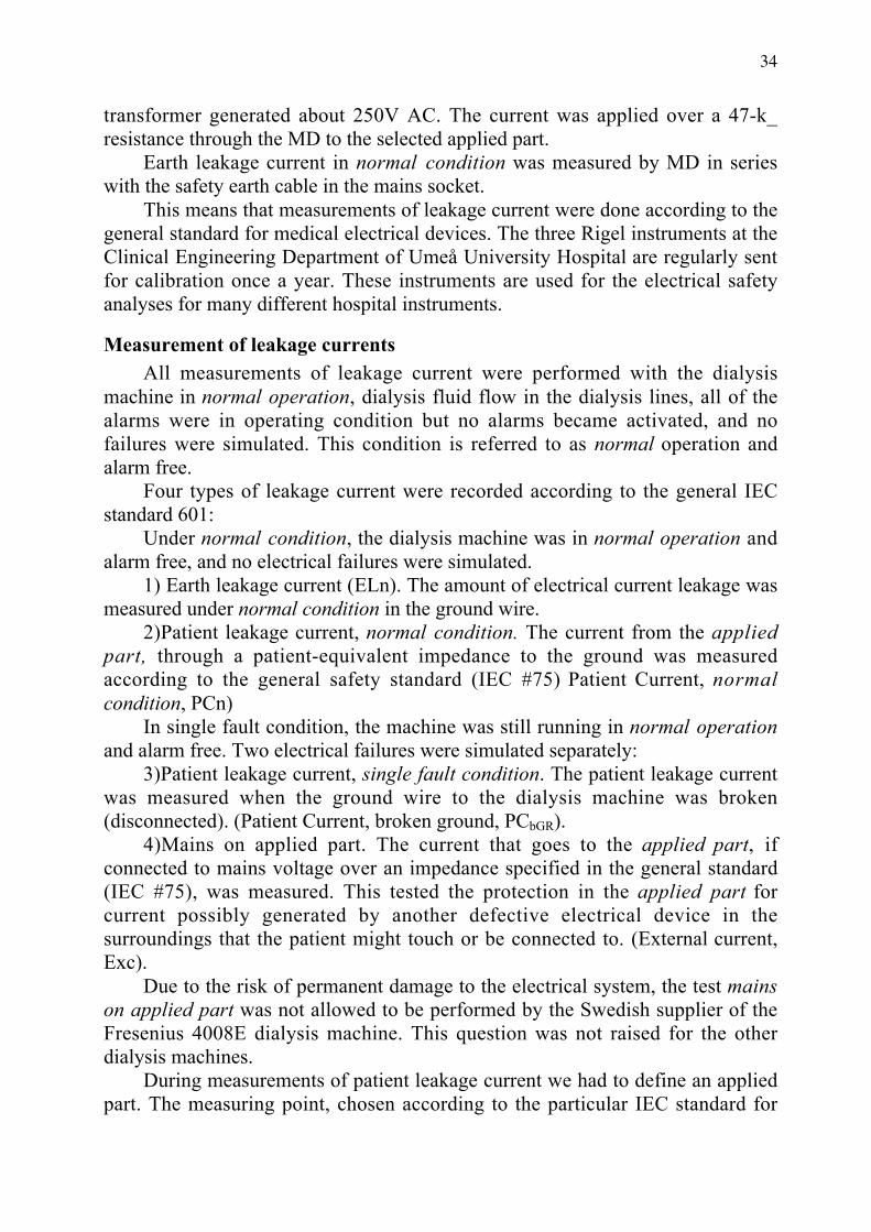
Measurement of leakage currentsAll measurements of leakage current were performed with the dialysis
machine in normal operation, dialysis fluid flow in the dialysis lines, all of thealarms were in operating condition but no alarms became activated, and nofailures were simulated. This condition is referred to as normal operation andalarm free.
Four types of leakage current were recorded according to the general IECstandard 601:
Under normal condition, the dialysis machine was in normal operation andalarm free, and no electrical failures were simulated.
1) Earth leakage current (ELn). The amount of electrical current leakage wasmeasured under normal condition in the ground wire.
2)Patient leakage current, normal condition. The current from the appliedpart, through a patient-equivalent impedance to the ground was measuredaccording to the general safety standard (IEC #75) Patient Current, normalcondition, PCn)
In single fault condition, the machine was still running in normal operationand alarm free. Two electrical failures were simulated separately:
3)Patient leakage current, single fault condition. The patient leakage currentwas measured when the ground wire to the dialysis machine was broken(disconnected). (Patient Current, broken ground, PCbGR).
4)Mains on applied part. The current that goes to the applied part, ifconnected to mains voltage over an impedance specified in the general standard(IEC #75), was measured. This tested the protection in the applied part forcurrent possibly generated by another defective electrical device in thesurroundings that the patient might touch or be connected to. (External current,Exc).
Due to the risk of permanent damage to the electrical system, the test mainson applied part was not allowed to be performed by the Swedish supplier of theFresenius 4008E dialysis machine. This question was not raised for the otherdialysis machines.
During measurements of patient leakage current we had to define an appliedpart. The measuring point, chosen according to the particular IEC standard for

35
haemodialysis equipment, was in the dialysis fluid line, at the site of theconnectors to the dialysis filter (dialyzer). A copper tube was inserted betweenthe dialyzer couplings to have a defined galvanic connection to an applied part.(See Fig. 2 below in method paper II, “x-paper I”) All measurements were donewith the system in operating condition, and we found normal conductivity,temperature and flow in the dialysis fluid lines. To also analyse the protection inthe dialysis machines against leakage current, possibly generated by ambientelectrical equipment going through to the patient and to the dialysis access, weused BF or CF mode on the Rigel instrument. The switch to select safety class,and the x10-scale button to select the best scale for reading the analogueinstrument, were used.
Statistical significance was determined using Student’s independent, 2-tailedt-test, and p < 0.05 was considered as significant. The numbers were small.However, the technical device in normal condition was assumed to have a verysmall variance for the variables measured, and therefore the above statistical testwas used.
Accuracy of the Rigel safety analyserThe analogue scales on the Riegel safety analyser are read visually. I
estimate that the accuracy of each reading at the upper end of each scale is asshown in Table 2.
Table 2. Estimated accuracy of a reading on the Rigel safety analyser
Estimated accuracy of a reading on each scaleScale on the Riegel safety analyser Estimated accuracy when reading the
upper end of the scale0-10 µA ± 0.2 µA
10-50 µA ± 1 µA50-100 µA ± 2 µA
100-500 µA ± 10 µA500-1000 µA ± 20 µA
1000-5000 µA ± 100 µA
Paper II, Blood usedThis in vitro investigation was done using blood from 8 persons after
informed consent (4 blood donors and 4 patients with polyglobulia orpolycythaemia vera). Blood concentrates from the donors were prepared asleukocyte-depleted concentrates of erythrocytes and were diluted by plasma thathad been stored frozen and then thawed to reconstitute the composition of regular

36
blood. From the 4 others the blood was received as whole blood using heparin asanticoagulant (5000 units/500 ml) in the collecting bag. The ethical committeeapproved the protocol.
Priming solution and dialysis fluidIsotonic sodium chloride, 0.9% NaCl (saline), from Pharmalink, was used as
priming solution in the blood lines. A Fresenius 2008C haemodialysis machineprepared the dialysis fluid from the two-components, concentrate SKF 203 andDuolys B, to a standard conductivity, according to standard procedure, and thatresulted in a solution of 14.25mS/cm and a temperature of 37.3 oC. This waschecked with a reference instrument, MESA MEDICAL/90 DX.
Electrical safety analyserLeakage current was analysed using a Metron QA-90 electrical safety
analyser (QA-90), programmed for class I, CF measurements. We tested the QA-90 in generating maximum current during mains on applied part by connectingthe “patient leads” on the safety analyser to the safety ground. The maximumreading on mains on applied part was 5200µA. According to the QA90 manualthe accuracy of current measurements is ± 2% of full scale ± 1 Least SignificantDigit (LSD), and the resolution is 1µA in the 0-100µA range and in the 100-1000 µA range. In the range 1.0 – 10.0 mA the accuracy is ± 1% ± 1LSD and theresolution is 1 µA. If the digital instrument, QA 90, shows 5200 ± 1 LSD, thatmeans that the deviation according to the display is from 5199 to 5201. Theanalyser is normally calibrated once a year, but at the time for the measurementsone calibration procedure was missing. Instead, there had been a service done onthe safety analyser at the time for calibration. In the service protocol there wasnoted that the calibration was “OK” but there was no calibration protocol. Themonth after the measurements the machine was recalibrated, and the protocolthen showed that the instrument was inside the specification and no adjustmentshad been necessary.
The patient leakage current was tested by applying a 100-µA source, and thereading was 100µA. Mains on applied part was tested over different calibratedresistances. For the QA-90 instrument, the calibration readings for mains onapplied part are shown in Table 3. The calibration of the resistances used in thecalibrating procedure for QA-90 are shown in Table 4.

37
Table 3. Mains on applied part (MOAP), QA-90 serial number: 11173, year2000-2006
Mains on applied part (MOAP), QA-90 serial number: 11173, year2000-2006
Calibration readings, µAN Minimum Maximum Mean Std. Deviation
MOAP,2M_ 6 122 123 122.7 0.51MOAP,5M_ 6 23 25 23.8 0.89MOAP, 50M_ 6 2.0 4.9 3.3 1.18
Table 4. Summary of the calibrations done on the resistances used in Table 3
Summary of the calibrations done on the resistances used in Table 3Resistance, _
N Minimum Maximum Mean Std. DeviationTR, 2M_ 6 1.99 2.01 2.005 0.009TR, 5M_ 6 9.97 10.08 10.045 0.054TR, 50M_ 6 49.83 50.37 50.201 0.262
Dialysis systemThe dialysis machine was equipped with an “extracorporeal circuit” and was
assembled from dialysis filter GFS +12 (Gambro, Lund Sweden) and tubing setfrom Baxter (Seraflo blood line ref: 236-467G) and a central dialysis catheter(CDC) was a Permcath (40cm, dual lumen, batch 17749-001, QuintonInstrument, Bothell, WA). The blood line had an inner diameter of approximately5mm, a length of 3550mm and a venous bubble trap with a diameter of 30mm.The inner diameters of the CDC lumens were 1.9mm. Dialysis needles wereconnected at the end of the blood lines, but they were inserted in the centraldialysis catheter as galvanic measuring points (applied part). Dialysis needleswere also used as measuring electrodes in the blood line system at various sites.
During this in vitro setting saline (0.9% NaCl) was used as priming solutionon both the blood and on the dialysis-fluid sides of the dialysis filter. During themeasurements of leakage current saline and then blood were used as the fluid inthe blood lines. The fluid was recirculated through the dialysis tubing set with adouble lumen (CDC) at the end. Needles were fixed into the lumen of the tubingset at the venous side of the CDC to measure electrical current within the fluidstream (Fig. 2).

38
Figure 2. In vitro measurement of leakage current
Saline, instead of dialysis fluid, was put in the dialysis filter. To avoidchanges in the ion concentration during the dialysis of this small fluid volume,approx. 450 ml, only a galvanic connection was made between the dialysis fluidtubes of the dialysis machine and the dialysis fluid compartment of the dialysisfilter. A metal tube (stainless steel) was connected between both filter connectorson the dialysis fluid lines of the dialysis machine (Fig. 2). A silicone tube linewas connected between both dialysis connectors on the dialyzer. The siliconetube line was cut and a small metal tube (stainless steel) was inserted in betweenthe silicone tube halves between the dialysate connectors of the dialyzer (Fig. 2,measurement point MP1). The metal connector at the tube fixed at the dialysisfluid part of the circuit was connected galvanically with a copper cable to themetal tube between the dialysis fluid connectors. Thereby the electricalconnection between the dialyzer and the dialysis tubes was present as it is usedduring standard dialysis treatment, without changing the ion concentration in thetest solution/blood during the experimental dialysis procedure. Measuring points(Fig. 2) were: MP1, dialysis fluid; MP2, blood tube just downstream from thedialyzer; MP3, the blood sampling site prior to the venous bubble trap; MP4, theblood line downstream from the venous bubble trap; MP5, the blood line justupstream from the site of the Luer connector (needle or catheter); MP6, insertedin the lumen at the tip of central venous catheter edge (“close to the heart”location if used during regular dialysis). All electrodes in the blood line wereinserted in the venous line except MP6 where one needle was inserted in eachlumen. They were used together as one measuring point (electrically in parallel).
1
2 3 4
5 6
bloodpumpsaline/blood bag
Dialysismachine
fluidsystem
dialysis filterLevel detector
central dialysis catheter
Metaltubes
Coppercable
Fig. 2
X paper I

39
The measurements were made using either manual mode (measurement ofmains on applied part) or automatic mode. The QA-90 changed the power lineconfiguration to the analysed equipment during the test at all test steps accordingto IEC 601-1. This resulted in several sequences of power loss. During automaticmode, the QA90 was set to start measurements 5 seconds after the power to thedialysis machine had been turned on, and we restarted the flow in the machine asfast as possible by pressing the dialysis start button. Measurements were recordedfor normal condition, single fault condition (broken protective earth connection,Fig. 2 in Paper II, Br1 open) and mains on applied part (leakage current from anexternal device connected to the blood line).
StatisticsPaired non-parametric statistics (Wilcoxon test) were performed for all
analyses. A significance level of p<0.05 was chosen. SPSS software was used.The highest values obtained are given in the text if not otherwise stated.
Addendum to Paper II. In vitro measurement of leakage current throughdiluted or concentrated blood during mains on the applied part
One blood bag of 0.4l blood from a haemochromatosis patient (male) wascollected. 15,000IU Heparin was injected into the blood bag, and the bag wasstored in a refrigerator.
A dialysis system was prepared (Fig. 3), and a single dialysis run wasperformed in vitro. Leakage current during mains on applied part was measuredas the blood was diluted by the addition of successive boluses of saline orconcentrated by ultrafiltration.

40
Figure 3. In vitro measurements of leakage current during mains on theapplied part through diluted or concentrated blood
A dialysis machine, Fresenius 4008H, equipped with a blood temperaturemonitor (BTM), was preparing dialysate from a Biosol 301 A- concentrate andBicbag (Fresenius). The composition of the concentrate was Na: 138, Cl: 109, K:3, Ca: 1, Mg: 0.5 Acetate: 3, Glucose: 5 (mmol/l). The conductivity was 14.1mS/sm2 and the temperature was set to: 37.5 oC. A Fresenius blood line (AV setFMC) was connected to a dialysis filter (F8HPS) and attached to the machine.The blood compartment was primed with priming saline from Meda and thedialysis side of the membrane by the dialysate. Needles (Bionic 16g) wereconnected to the blood line and the arterial needle was inserted in the blood bagand the system was filled up with blood. The venous needle was also inserted intothe blood bag and the blood was recirculated at a blood flow of 200 ml/min. TheQA90 instrument applied part connector was connected to the venous needle.
Measuring procedure: When the arterial temperature recording on the BTMwas stable the leakage current during mains on applied part was recorded andblood samples were taken. Levels of albumin, Haemoglobin (Hb), erythrocytevolume fraction (EVF), erythrocyte particle concentration (EPK) were analysed.
Dilution procedure: Saline was injected into the blood line in steps of 60mland the measuring procedure was repeated. The dilution procedure was repeated8 times. (Two blood samples were missed).
Ultrafiltration procedure: The dialysis machine was programmed toultrafilterd a volume from the recirculating system and when it was finished the
5
bloodpump
saline/blood bag
Dialysismachine
fluidsystem
dialysis filter
Level detector BTM
fig 3
Br1
QA 90
253V AC
Ri
Patientleakagecurrent
Mainsonappliedpart
Connections to applied part (MP 6)

41
blood was recirculated for a period of time corresponding to the temperaturestabilisations in the measuring procedure (approx. 10 min). The mains on appliedpart reading was monitored, and when stable, a new measuring procedure wasbegun. Three ultrafiltration procedures were done stepwise.
Calculation of “bag difference”: The concentration differences duringdilution and ultrafiltration were calculated, and blood sample volumes wereincluded in those calculations.
Test for correlation: The bag difference and the levels of the analysedsubstitutes from blood samples were tested for linear correlation with leakagecurrent using Pearsons test for correlation.
Paper III, dialysis systemThe dialysis system used was Fresenius A 2008 C. Buffer solutions used for
dialysis fluid were D210 (acid concentrate, Gambro, Lund, Sweden) togetherwith buffer solution Duolys B (Fresenius), blended to a final concentration of Na140, Cl 110, Mg 0.5, Ca 1.75, K 3.0, HCO3
- 34 and acetate 3.0 mmol/l by themachine. The same type of dialyzer and tubing set were used each time. Todecrease the dilution factor and priming volume, the tubing set was shortened.The dialysis machine was disinfected by heat prior to each use. The dialyzer wasrinsed with 1.5 litre saline before dialysis. This fluid was mostly removed beforethe experiment. In all tests dialysis fluid flow was 500 ml/min, blood flow was100 ml/min, and dialysis fluid temperature was 37.0
oC. Dialysis needles were
inserted in sampling ports prior to and past the dialyzer and used as parallelconnected electrodes in the blood compartment. Approximately 350 g blood wascollected from each of eight blood donors after informed consent was obtained.Seven of them were healthy male blood donors and one was a haemochromatosispatient. Each blood bag contained 1000 Units heparin (in one bag only 800Units). The priming fluid (saline) in the tubing and dialyzer caused a partialdilution. Hollow-fibre dialyzers were used. The dialysis membranes werehemophan membranes and had been steam-sterilised (GFS +12, Gambro).
Paper III, methodsBlood from the donors was recirculated in the extra corporeal system of the
dialysis machine, and the dialysis fluid flow was set at 500ml/min. During this invitro dialysis, blood samples were taken for analysis every 15 minutes. After 1hour of in vitro dialysis DC voltage was applied between the needles and theground connector in the dialysis fluid. The voltage was increased to achieve anelectric current in the system of maximum 1.5 mA. This current was consideredas a provocation test to indicate if leakage could have any effect on the blood-membrane interaction. A second limit was used to the applied DC voltage thatforced the current. It was limited to 50V, so in some runs the current was under1.5mA.

42
The voltage limit was selected due to the maximum DC voltage differencesin the electronics in the machines used (+25V and -25V). The anode was on theblood side, except in one run where, by mistake, the cathode was the bloodelectrode. The blood sampling every 15 min persisted during exposure to theelectric current in the system until a total of 1.5 hour in vitro dialysis had beenperformed.
Blood sampling and analysisThe blood samples were analysed for concentrations of complement
component C3d, albumin, haematocrit and electrolytes. Blood samples for C3dwere immediately cooled on ice and kept so until centrifugation. Aftercentrifugation the plasma samples were frozen at -20o until analysis. C3d wasanalyzed with rocket immune electrophoresis technique (Stegmayr, 1989 #125).The values were adjusted to the serum albumin and haematocrit to correct theC3d samples for the dilution by priming fluid or eventual dialysis fluid imbalance(effect of an eventual ultrafiltration) during dialysis.
StatisticsSoftware (Statworks) was used for analysis of data by non-parametric paired
Wilcoxon signed rank test. Later analyses were done with SPSS. A two tailedP<0.05 was considered as significant.

43
Paper IV,This paper can not be e-published according to the copyright rules. Until peerreview is finished it is only described briefly:
Forty-five patients were investigated with ECG and by Poincaré analyses
arrhythmia where evaluated before connection of the dialysis tubes to the patient,
shortly after the start, before the end of the dialysis and after disconnection of the
tubes.
Paper V,The paper “Air microbubbles pass the security system of the dialysis devicewithout alarming” can not be e-publish yet according to the copyright rules.Different methods were used to in vitro evaluate imaginable bubbles silentlypassing the air detector.
An abstract from the ESAO Congress in Umeå 21-24 June 2006 of a part of thiswork was published in:Air microbubbles pass the security system of the dialysis device withoutalarming. Jonsson P, Karlsson L, Forsberg U, Gref M, Stegmayr C, StegmayrB. International Journal of Artificial Organs, 2006, 29 (5):523.
The full text article will soon be available:Jonsson P, Karlsson L, Forsberg U, Gref M, Stegmayr C, Stegmayr B. Airmicrobubbles pass the security system of the dialysis device without alarming.Artif Organs, in press, 2007.

44
RESULTS
Paper IAccording to these data all of these devices apply to their given safety level (B)when filter couplings for the dialysis fluid are considered as applied part. Theyeven comply with one step higher degree of safety (BF) but they do not complywith the recommended safety level for cardiac applications (CF).Figures 7-10 show the distribution of the single data for each device undervarious conditions. The limit for cardiac floating is given by a hatched line.
Figure 7. ELn Earth leakage, normal condition
0 1 2 3 4 560
80
100
120
140
160
180
Leakage Current, µA
GambroAK10 Gambro
AK100
Fresen.2008C Fresen.
2008E
Fresenius4008E

45
Figure 8. PCn patient current, normal condition or patient leakage currentnormal condition in IEC 601-1
Figure 8: Plots for each measurement of leakage current for different devices-normal condition. (The dot at 40 µA at 2008C is a high value due to a failure in acapacitator in a conductive level detector in the fluid system. After service theleakage current in normal condition was 3 µA the following two years. The valueafter repair, 3 µA, was used in the paper I statistic.)
0 1 2 3 4 50
10
20
30
40
Leakage Current, µA
fig 8 PCn patient current normal condition or“patient leakage current normal condition” in IEC 601-1
GambroAK10 Gambro
AK100
Fresen.2008C Fresen.
2008E
Fresenius4008E
CF limit
Safety limit for cardiac floating (CF) 10µA recommended in IEC 601-1for cardiac application respectively 100µA for BF and B equipment

46
Figure 9. Patient current, broken ground, PCbGR or patient leakage currentsingle fault condition in IEC 601-1
Figure 9: Plots for each measurement of leakage current for different devices-patient leakage current - single fault condition.
0 1 2 3 4 540
60
80
100
120
140
160Leakage Current, µA
GambroAK10 Gambro
AK100
Fresen.2008C Fresen.
2008E
Fresenius4008E
Safety limit for cardiac floating (CF) 50µA recommended in IEC 601-1 forcardiac application respectively 500µA for BF and B equipment
CF limit

47
Figure 10. Exc, external current or mains on applied part in IEC 601-1
In Table 7 the statistical analyses for comparison between devices are given.Since the material is small the statistics are given using the Student’s test withcorrection for skewed distribution (using Levenes test) but also non parametricstatistics (Mann Whitney).For the reader it is more important to notice the data in relation to the safetylimits set in IEC 601-1. For comparison the limits for Cardiac applications CFand other applied parts B and B F in normal condition (PCn), single faultcondition (PCbGR) and mains on applied part (Exc) are inserted in the figures.
0 1 2 3 4 50
1000
2000
3000
4000Leakage Current, µA
GambroAK10 Gambro
AK100
Fresen.2008C Fresen.
2008E
Fresenius4008E
Safety limit for cardiac floating (CF) 50µA recommended in IEC 601-1 forcardiac application, respectively 5mA for BF and no limit for B equipment
Limit for BF
CF limit

48
Table 7. Earth leakage compared between dialysis machine models.P-values are given according to Students test/Mann Whitney (non parametric test)
Earth leakage P- values are given according toStudents test/Mann Whitney (non parametric test)Machinemodel:
AK10 AK100 Fr 2008C Fr 2008E
AK100 0.001/0.008Fr 2008C ns/ns ns/0.024Fr 2008E 0.009/0.051 ns/ns ns/nsFr4008E 0.001/0.012 ns/ns ns/0.028 ns/ns
Table 8. Patient current, normal condition (PCn) compared between dialysismachine models PCn
PCn patient current, normal condition P- values are givenaccording to Students test/Mann Whitney (non parametric test)Machinemodel:
AK10 AK100 Fr 2008C Fr 2008E
AK100 0.002/0.008Fr 2008C ns/ns ns/nsFr 2008E 0.005/0.049 0.001/0.047 ns/nsFr4008E 0.001/0.014 0.001/0.013 ns/ns ns/ns

49
Table 9. Patient Current,,single fault condition compared between dialysismachine models.(Broken ground, PCbGR)
Patient Current,,single fault condition (Broken ground, PCbGR)P- values are given according to Students test/Mann Whitney(non parametric test)
AK10 AK100 Fr 2008C Fr 2008EAK100 0.097/nsFr 2008C 0.020/0.044 0.037/0.016Fr 2008E ns/ns 0.003/0.033 ns/nsFr4008E ns/ns ns/ns 0.043/0.026 0.022/0.049
Table 10. Exc, external current or mains on applied part compared betweendialysis machine models.
Exc, external current or mains on applied partAK10 AK100 Fr 2008C
AK100 0.004/0.008Fr 2008C 0.001/0.024 ns/0.010Fr 2008E 0.001/0.051 0.001/0.016 ns/nsFr4008E* -* - -
Paper IITables 11 and 12 and Figures 11and 12 show data from automatic safetymeasurements according to IEC 60-601-1 using the safety analysis device QA90.Note that differences appeared unexpectedly during the automatic mode of safetymeasurement with the QA90 device. This depended upon the intermittent powerto the dialysis device as determined by the QA90. The QA90 turned the currenton and off automatically to perform the different safety measurements. When thecurrent was turned off an air gap appeared in the bubble trap and no current flowcould be measured. This air gap remained after the power was turned on until theblood pump had started.Table 11 shows data from eight runs with saline in the blood lines during normalcondition. Earth leakage current (ELC) was median 143 (range 133-150 µA)while patient leakage current (PLCNC) was 11 µA (range 10-14) at measurementpoint (MP) MP1 and 0 at point MP6.

50
Table 11. Leakage current through blood lines in normal condition usingsaline as a fluid
Earth leakage current (ELC) and patient leakage current(PLCN) during normal condition using saline as fluid
MP1 MP2 MP3 MP4 MP5 MP6uA
Series ELC PLCNC PLCNC PLCNC PLCNC PLCNC PLCNC1 142 11 0 0 0 0 02 143 0/* 4 0 0 0 03 150 0/* 5 0 0 0 04 143 0/* 4 3 0 0 05 143 14 3 2 0 0 06 143 11 5 3 2 0 07 133 10 5 3 2 0 08 144 13 6 3 2 0 0
MP1-MP6 indicate measurement points 1-6.* indicates probably due to loss of connection.
Figure 11 shows data from 8 runs with saline in the blood lines in singlefault condition. Patient leakage current was median 132 µA (range 127-143)measured at MP1 and median 47 µA (range 4-128) at MP6. The solid lineindicates mean values. The dashed line indicates CF limit.

51
Figure 11. Leakage current, blood in bloodlines, single fault condition
Table 12 shows data from a setting using normal condition with 8 runs withblood in the blood lines. Earth leakage current (ELC) was median 147 (range142-152 µA) while patient leakage current (PLCNC) was median 19 µA (range16-21) measured at MP1. Patient leakage current (PLCNC) was 2 µA in two and0 in six of the runs at MP6.
0 1 2 3 4 5 6
Measuring points
20
40
60
80
100
120
140
160
Leakage current, µA
CFlimit

52
Table 12. Leakage currents through blood lines containing blood duringnormal condition
Earth leakage current (ELC) and patient leakage current (PLCNC) in µAusing blood as a fluid during normal condition
MP1 MP2 MP3 MP4 MP5 MP6µA
Series ELC PLCNC PLCNC PLCNC PLCNC PLCNC PLCNC %PLCOE1 142 16 7 3 2 0 0 02 146 20 11 4 4 0 2 13 144 19 9 4 5 0 0 04 147 19 10 4 4 0 2 15 147 21 9 4 3 0 0 06 148 19 9 4 4 0 0 07 152 19 7 3 3 0 0 08 150 20 8 3 3 0 0 0
MP1-MP6 indicate measuring points 1-6. The percentage of patient leakagecurrent in relation to earth leakage current is calculated (%PLCOE).
In single fault condition (Fig. 12) patient leakage current was median 134.5 µA(range 133-142) measured at MP1 and median 68 µA (range 35-118) at MP6.

53
Figure 12. Leakage current through blood lines containing saline duringsingle fault condition
Table 13 and Figures 13 and 14 show data from 8 runs using the test mainson applied part (IEC 60-601-1) measured in manual mode (stepwise). This testsimulates leakage current generated by other equipment connected to the patientand corresponds to a single fault condition. Either blood, Figure 14 or saline,Figure 13, was used to perfuse the “blood lines”, the flow was either off (-), on(+) with flow 80 ml/min or 160 ml/min. Measurements were only performed atMP6 for flow 160 ml/min. When using saline in the blood lines the patientleakage current at MP6 was median 1008 µA (range 674-1213) with flow of 80ml/min.
When blood was used the patient leakage current at MP1 was median 3964(range 3933-3972 µA) and at MP6 median 610µA (range 441-662). The ratio ofretained LC at MP6 was calculated using the LC at MP6 related to the LC at MP1and adjusted into percentage, which resulted in a median of 15.5% (range 11.1-16.8 %) leakage current.
0 1 2 3 4 5 6
Measuring point
0
40
80
120
160
Leakage current,µA
ELC

54
If the LC at MP6 with a blood flow of 80 ml/min was compared with datawhen blood flow was increased to 160 ml/min, the LC increased by about 12%(0.7-24%, p=0.012).
When a single fault was simulated on the dialysis device with blood in thetubes the leakage current was lower at M3 than at M2 (p=0.025), lower at M6than at M5 (p=0.012) but not different between the other sites close to each other(Table 12).
When a fault of mains on applied part was simulated with blood in the tubes,leakage current was significantly lower at the more distal point by comparisonfrom MP1 and MP2, MP2 and MP3 until MP5 and MP6 (p=0.12). Suchsignificant differences were also found using saline (p<0.019).
Data at MP5 show that the leakage current was greater than at MP6. MP5 isthe place where a dialysis needle is inserted into the AV fistula (blood line) of apatient. Since these data show that blood conducts leakage current, the risk ofhaving leakage current through an AV fistula (MP5) is not negligible. The otherpoints (MP2-4) are reported to show the conductive dynamics in the blood-linesystem. To estimate the drop of current, the measurement at the starting point,MP 1, is important.
The blood used was analysed for its concentration of haemoglobin, albumin,sodium, chloride, leukocytes and platelets. When these variables were comparedusing univariate analysis the leakage current at MP6 during single fault conditionwas correlated to Na+ concentration (r2=0.60, p=0.024) but not to the otherparameters. The LC at MP6 during mains on applied part correlated inverselywith albumin (r2=0.81, p=0.0022) and haemoglobin (r2=0.62, p=0.021).
The impedance in the tubing system (Z(isolation)) was calculated frommeasured current during mains on applied part. The formula was based on theassuming of clean resistance, no inductive or capacitive component:
U= (Z(isolation)+ R(inner resistance)) x I(leakage current);U/I=Z+R; (U/I)-R=ZSaline in blood lines (1008 µA (range 674-1213)): (253/0,001008)-
47000=203992 _, approximately ≈ 200 k_ (range 160-330)Blood in blood lines 610µA (441-662): (253/0,000610)-47000= 368000 _; ≈
370 k_ (range 340-530). Thus, the total impedance range was 160 - 530 k_ withflow 80 ml/min.

55
Table
13. Leakage current during the test mains on applied part, flow on/off
Median values of leakage current either with blood (Bl) or saline (Na) in thetubes. In addition, the experiment included a model with dialysate flow off(Dia-, 0ml/min) or on (Dia+, 500ml/min) and blood or saline flow off(Bl-, Na-) or flow on (Bl+, Na+).
Blood series Saline seriesMeasurepoint (distanceto dialyzer)
Bl-Dia-
Bl-Dia+
Bl+Dia+
Bl+Qb160Dia+
Na-Dia
-
Na-Dia+
Na+dripDia+
Na+Dia+
Na+Qb160
Dia+1 (0) 3574 3945 3959 325
23795 3936
2 (50mm) 3072 3324 3358 2972
3451 3421
3 (812mm) 1582 1635 1728 2018
2291 2206
4(1370mm)
1127 1091 1341 61 53.0 481 1854
5(3520mm)
598 587 749 113 107 242 1160
6(3950mm)
471 461 591 661 121 34.5 179 980 1058
The flow through the tubes (Qb) was set at 80 ml/min or 160 ml/min (Qb160)for measurement at MP 6. When set at 80 ml/min and with saline in the tubesdripping occurred in the venous bubble trap.

56
Figure 13 Saline solution in the tubes, mains on applied partLeakage current through bloodlines containing saline. Test mains on applied part at measuring point 1 – 6 .using priming solution(NaCl) in the tubes.
0 1 250
3812
41370
53520
63940 (mm)
0
1000
2000
3000
4000
Leakage current,µA
No dialysate on
Dialysate on
Blood flow 80 ml/min
Measuring point number/ distance from filter
CFlimit
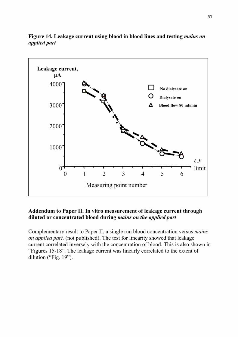
57
Figure 14. Leakage current using blood in blood lines and testing mains onapplied part
Addendum to Paper II. In vitro measurement of leakage current throughdiluted or concentrated blood during mains on the applied part
Complementary result to Paper II, a single run blood concentration versus mainson applied part, (not published). The test for linearity showed that leakagecurrent correlated inversely with the concentration of blood. This is also shown in“Figures 15-18”. The leakage current was linearly correlated to the extent ofdilution (“Fig. 19”).
0 1 2 3 4 5 60
1000
2000
3000
4000
Leakage current,µA
Measuring point number
No dialysate on
Dialysate on
Blood flow 80 ml/min
CFlimit
58
Figures 15 Correlation albumin concentration vs. leakage current.
In-vitro albumin concentration, dialysis with diluted / ultrafiltered bloodbag. Mains on applied part measured at needle site (MP5).
r2=0.92p<0.001
Fig. 15

59
Figures 16 Correlation Hb concentration vs. leakage current.In-vitro Blood concentration, dialysis with diluted / ultrafiltered blood bag. Mainson applied part, needle site (MP5).
r2=0.97p<0.001
Fig. 16

60
Figures 17 Correlation EVF concentration vs. leakage currentIn-vitro Blood concentration, dialysis with diluted / ultrafiltered blood bag. Mainson applied part, needle site (MP5).
r2=0.98p<0.001
Fig. 17

61
Figure 19. Correlation between blood-volume changeBag difference, y-axis and leakage current in vitro. Measurements wereperformed with blood that had been diluted or ultrafiltered, mains on appliedpart, at measurement point 5.
r2=0.93p<0.001
Fig. 19

62
Paper IIIFigure 20 show the median percent change in C3d levels versus time. There was asignificant increase in C3d throughout the whole time series (p<0.05). Theincrease between 0 and 30 minutes was greater than that between 30 to 60minutes (p=0.018). The increase in C3d was greater between 60 and 90 min thanbetween 30 and 60 minutes (p=0.018). There was no difference in the increase at0 to 30 and 60 to 90 minutes (see Fig. 20).The erythrocyte volume fraction (haematocrit) did not change significantly duringthe tests (see Fig. 21 and 22).
Figure 20 Change in C3d levels versus time
0 20
40
60
80
100
0
100
200
300
400
Observation period, minutes
Change in C3d from baseline, %
Current connected
worst scenarioexpected
physiologicallyexpected
Fig. 20

63
Figure 21. Change in variables during series 6
0 20 40 60 80 100
Observation period, minutes
96
100
104
108
112
116
Cha
nge f
rom
bas
elin
e, %
albuminhaemoglobinEVFEPCLPC

64
Figure 22. Correlation between serum albumin and blood haemoglobinduring series 6
Paper IVHeart rate decreased significantly after start of dialysis, was thereafter not
significantly changed while a significant increase occurred after disconnection of
the dialysis. Arrhythmia was more pronounced during the end of dialyses in 13
(35%) of the patients while it was improved in 2 patients and unchanged in 28.
Atrial fibrillation developed in 2 patients while 6 had atrial fibrillation already at
start of the investigation. No significant differences were seen between those with
central dialysis catheter and those with peripheral access. Changes in arrhythmia
occurred close to start but also close to finishing the dialysis.
28 29 30 31 32 33
S-Albumin, g/L
98
100
102
104
106
108
110
112
B-H
aem
oglo
bin,
g/L
r=0.97
Correlation serum albumin and blood haemoglobin during series 6

65
Paper VThe full text article will soon be available:Jonsson P, Karlsson L, Forsberg U, Gref M, Stegmayr C, Stegmayr B. Airmicrobubbles pass the security system of the dialysis device without alarming.Artif Organs, in press, 2007.
DISCUSSION
This doctoral thesis has focused on safety issues related to the processing ofblood during haemodialysis of patients. The amount of leakage current presentlyallowed for state of the art dialysis devices is based on the B level of safety.However, that level does not take into account the use of the central dialysiscatheter (CDC). Proximity to the heart should require a cardiac floating safetylevel. The question of leakage current is important because only a small currentalong a catheter near the heart could be fatal to the patient. The resistance in theblood lines and the presence of air in the blood lines might also affect thepossibility for leakage current to reach the patient’s heart. Leakage current in theblood lines might also affect the blood itself. Several of the studies in this thesiswhere not possible to perform directly on patients, since the risk for severecomplications was considered too high. Therefore, several experiments wereperformed in vitro.
Since the 1990s the IEC601 standards are relatively “open standards.” Thisis because if a standard would describe everything in detail there would be no usefor the manufacturer to design or construct something better than the standard. Insuch a case a very detailed safety standard could impair the development of saferprocedures. Therefore, in many cases the standards do not state absolute limits.Instead, they include somewhat vague statements that require a system to protectthe patient from hazardous outcome according to specific parameters. It is hopedthat the manufacturers will constantly compete with each other to improve thesafety of their devices and therefore offer machines that are safer, easier to use,and less expensive. However, that requires that the consumers are aware of therisks, how those risks can be measured / compared, and costumers looking fortechnique that reduce or avoiding this risks. Without background knowledgeamong the consumers, it would become a competition without rules for themanufacturers, and other considerations during commerce. In that case an openstandard does not promote better safety. I hope that the data from this doctoralthesis will add some background knowledge and will promote a improvement ofdialysis equipment in the future.

66
Leakage current Paper I - IVPaper I describes issues regarding safety against electric shock. An AV
fistula or graft allows peripheral access to the patient’s blood stream. If thehaemodialysis treatment is considered as a peripheral connection to the patient,the data showed that leakage currents were within the present safety limits forbody and body floating (IEC 60601-1 #75). That conclusion relates to themeasurement of patient leakage current in normal condition, single faultcondition and mains on applied part performed according to the IEC standard(IEC #75) –Figure 7-10.
Although the leakage current in single fault condition (disconnected ground)is higher, it might be reduced by the resistance in the blood lines and filteraccording to the conclusion by M. C. Deller in 1974. He wrote that ”The dialyzerand lines represent a protective impedance of some 400kohm between the patientand the dialysis machine” and “As far as primary electrical hazards areconcerned, dialysis should be considered as being a relatively safe procedure”(Deller, 1979 #74). Is that correct? Is it sufficient protection even with a centraldialysis catheter?
A central dialysis catheter (CDC) is not unusual for dialysis patients, and it isusually placed close to or within the heart. The data in Paper I indicated that theleakage current measured in filter couplings could constitute a safety problem ifthe equipment were used in a cardiac application, i. e., with a CDC. The leakagecurrent during mains on applied part (fig 10) was at alarming levels in all testedmachines as compared to (1) the recommended safety levels for cardiacapplications and the probabilities for ventricular fibrillation stated in the generalstandard (IEC #75) and (2) studies performed on hearts of humans and dogs(Starmer, 1973 #79; Watson, 1973 #81). Such high values, except one recording,were recorded after maintenance, and the leakage current could possibly havebeen even higher before maintenance. For example, salt splashes on the electricalcomponents in the fluid system might increase all types of leakage currents.Dialysis patients with a CDC could be at risk if the dialysis fluid and blood in thetubes lead enough leakage current. Although Deller (1979) had no concerns inthis regard, the analyses in Paper II were performed to clarify the risk for leakagecurrent through the blood lines.
The data in Paper II pointed out that the safety level when using a CDC witha modern, state of the art dialysis machine was not within the safety level forclass CF recommended in IEC 60-601-1 (IEC #75). According to the data inPaper II for the dialysis device tested there is very little risk for ventricularfibrillation during normal condition (table 11 and 12) according to the generalstandards and its references (IEC #75; Starmer, 1973 #79; Watson, 1973 #81).However, the safety limits for class B in normal condition are not considered safefor a cardiac application according to the same references. Paper II showed thatleakage current could travel via the blood lines and filter when they containedsaline or blood. During the single-fault condition, (broken ground connection),

67
the leakage current increased, and the safety situation worsened (Figure 11 and12). That dialysis device showed a maximum current of about 130 µA, and that ismore than 2_ times the safety limit recommended in the general standard. Thatamount of current corresponds to >10% probability for ventricular fibrillationaccording to the probability table in the general standard (IEC 60601-1 #75). Aneven greater risk occurs if the access point becomes grounded. If the dialysis fluidbecame grounded the access point would be considered as an electrical groundpoint in the patient. For a CDC patient this would be within or close to the heart.Leakage currents from all electrical equipment that the patient touched at thesame time are likely to more or less sum up at the access point in the patient. Thisleakage current(s) can be generated by all kinds of electrical equipment withdirect or indirect contact with the patient.
According to the general standard (IEC 60601-1 #75) and its referencesaccording to microshock (Starmer, 1973 #79), (Watson, 1973 #81) ventricularfibrillation can occur at current below the level of perception. For medicalelectrical equipment the upper limit for touch current in normal condition is 100µA. Since the patients today can be active and move around the equipment duringthe dialysis treatment. They can come in contact with other electrical devices.Although many equipments have touch current below 50µA they are allowed togenerate 100 µA and in single fault condition 500 µA are tolerated. Withgrounded dialysis fluid and dialysis access, there is no safety class for electricalequipment with a safety limit for touch current that could be considered safe for adialysis patient with a CDC (below 10 µA in normal condition and below 50 µAin single fault condition.
During mains on applied part (table 13, figure 13 and 14) the measuredmean current was 661 µA using blood in the lines. That exposure could be fatal ifit were concentrated around a direct cardiac application. Using saline, the normalpriming solution, the exposure was even greater when the blood pump was set ata flow of more than 80 ml/min. This risk is not within the limits andconsiderations in (IEC 60601-1 #75) and (IEC 513, 1994 #121). This indicatesthat the classification of the applied part in a dialysis system intended for use witha central dialysis catheter should be cardiac floating (CF). The industrialrepresentatives in standardisation committees have been of the opinion that CF-level would be difficult and expensive to obtain. However, there already is at leastone dialysis machine for intensive care use, for so called continuous renalreplacement therapy (CRRT), and it has no ground connection in the dialysisfluid and is classified as cardiac floating (Multi Filtrat). Unfortunately, anothermodel of CRRT dialysis system, without ground connection that might hadapplied with cardiac floating limits, was involved in an incident. The CRRTmachine generated artefacts on the patient-monitoring system, which resulted inan incorrect diagnosis and unnecessary and potentially harmful treatment when

68
the artefacts were mistaken for arrhythmias. To avoid recurrence, the fluidpathway of the CRRT machine was grounded. This is an example of a change inconstruction to avoid one risk (interference due to static electricity) thatunintentionally generated a secondary risk (due to leakage current). There theproblem that caused the incident was solved (Graansma, 2004 #118), but thesolution probably increased the risks related to future leakage currents around thedialysis access.
The 50-µA limit for cardiac applications in the general standard (IEC60601-1 #75) has been disputed during the time I have been doing these studies.Swerdlow et al. studied the effects of current applied in the heart of closed-chesthumans. They reported that leakage current caused cardiovascular collapse atlevels below the “ventricular fibrillation threshold,” and they suggested using 20µA -- instead of 50 µA -- for leakage currents lasting longer than 5s in the safetystandard (Swerdlow, 1999 #80). The mechanisms for cardiovascular collapse atlevels below the ventricular fibrillation threshold have been investigated by(Malkin, 2001 #100; Vigmond, 2001 #102).
Paper II also pointed out that the impedance of blood lines and filters,calculated by Deller, is not a constant. The ability for the dialysis system toconduct leakage current can vary considerably with the treatment parameters. Thepriming solution used at the start and often at the end of treatment provides lessimpedance than blood. The leakage current through the system during thetreatment contains blood with a wide range of concentrations due to ultra-filtration and sometimes dilution during infusion (figure 15-18). Of course, theconductivity of the dialysis fluid and the temperature are also important. Duringelectrical safety analysis of the dialysis access point these parameters should beset to mimic the most dangerous condition (worst case) according to the ability ofthe extracorporeal system to conduct leakage current in a treatment situation. Forexample, the highest tolerated conductivity and temperature in the fluid systemand priming solution or diluted blood in the blood system and no ultrafiltrationwould conduct the greatest leakage current.
Paper II also pointed out the importance of flow and avoiding air gaps in thesystem (tubes and filter) during electrical safety analyses which involvemeasurement of leakage currents in a dialysis access point (Figure 13). If any airgap is present during a measurement the result will not be representative for atreatment situation. Manual safety analysers or manual measuring mode isrecommended.
The central dialysis catheter is used with a long time of exposure to thepatient. The access point is close to or within the heart of the patient and shouldbe considered as a cardiac application. Therefore, it is reasonable that theelectrical safety of that applied part for a dialysis system should be classified ascardiac floating.
The measuring of leakage current in blood lines of a dialysis system shouldbe done with flow in the system.

69
For dialysis machines classed B or BF and used together with a CDC,measures are needed to limit potential leakage currents from all electricalequipment that may come in contact with the patient such as. Restrictive use ofelectrical equipment. Extra redundant protective earth connector have beensuggested and separating transformers are available. Frequent electrical safetyanalyses could be advice. The measures should include all electrical equipmentand not only the dialysis machine to reach a safety level, for a dialysis patientwith CDC, according to the general standard. Cardiovascular collapses orventricular fibrillation during haemodialysis using CDC should been handled asan accident or incident and demand a technical investigation of the leakagecurrent. All electrical equipment in the surroundings around the patient should beincluded in the investigation.
There is also the question about leakage current and a possible effect on thepatient’s blood (Paper III) during dialysis. C3d was chosen as a marker for apossible interaction between leakage current and the blood because it is quitestable and is a reliable marker for complement activation. Complementactivation, in turn, then affects many other processes in the blood. To detect anypossible effect of current on C3d, even if studied in only a small series of bloodsamples, a current leakage of DC 1.5 mA was used. This level is within the limitthat could be expected for mains on applied part. The DC leakage currentaffected the C3d. Even leakage current of a smaller magnitude would probablyenhance the blood-membrane interaction as measured by C3d levels. Paper IIIfound no evidence that haemolysis affected C3d, but the study could not rule outthe risk for more side effects for a patient treated with a dialysis device that hasan increased level of leakage current as compared to normal condition.
In patients exposed to leakage currents in the range up to 34 µA, normalcondition according to class B and single fault condition according to class CF,Paper IV showed a significant change in heart rate, as compared to the normalcondition, after connection and disconnection of the tubes (electrodes) from thedialysis device to the patient. Normally, one would expect an increase in heartrate when potassium is decreased as well as when fluid is withdrawn from thepatient. These data showed the reverse. In addition, some patients experiencedmore arrhythmia, especially at the end of dialysis. This arrhythmia on someoccasions disappeared promptly after disconnection of the dialysistubes/termination of dialysis. These data do not rule out the possibility thatleakage current, even in normal conditions, may interfere with the cardiacfunction, especially in more vulnerable patients.
Distribution of air microbubbles, Paper VWhile investigating leakage current the importance of an air gap as
resistance was evident. Parallel findings indicated that air could pass the safety

70
system into the venous blood line together with the blood flowing into the patient.To further clarify this issue, Paper V dealt with the risk for air or gas infusion intothe patient from the extracorporeal circulation used in haemodialysis.
For the tested safety systems with the air detector working as a level detectorin the venous chamber, the proper installation of the venous chamber according tothe manual(s) for the system seems essential. If the venous chamber is mountedwith a level detector close to the bottom of the chamber, the probability foradverse events without inducing an alarm is not negligible. Paper V showed thatmicrobubbles of air could pass the safety systems in all tested machines withoutinducing an alarm because they were small, and not too many occurred at thesame time. The fluid level in the venous chamber is of importance for the amountof bubble leakage. A recent in vivo study reports the same situation duringstandard dialysis treatments (Stegmayr, 2006 #117). This supports thecalculations by Polashegg and Levin (Polaschegg, 2004 #54) that small bubbleswith less buoyancy follow with the flow down in venous chambers. They alsodiscuss the physics of degassing and redissolution of gas during decompressionand compression in a dialysis blood line. Those authors also concluded that smallbubbles collapse into the blood before they pass into the patient access, andtherefore, according to them, silent passage of air bubbles might not be a directproblem.
The risk for microbubbles and air contamination to the patient isstrengthened by Woltman et al. They detected microembolic signals downstreamfrom a dialysis access that could be of gaseous or solid origin using ultrasound(Woltmann, 2000 #14). Rolle et al. also detected microembolic signals (MES)downstream from the dialysis venous access during haemodialysis. The intensityof the MES indicated that they corresponded to synthetic particles ormicrobubbles, which were not detected by the air-trap (Rolle, 2000 #7). Thecalibration procedure for the Hatteland equipment used in Paper V showed that,in a deaired system, the tested blood pump and lines did not generate manysynthetic particles. In this model no circulation of synthetic material wasidentified, but a lot of bubbles were identified. In addition, bubbles in blood staylonger “alive” than in water solutions because of coating by protein layers (Barak,2005 #66). These microbubbles could also cause adverse effects to the endotheliain capillaries and alveoli which might explain the pulmonary morbidity amongdialysis patients (Barak, 2005 #66). In case the micro bubble distribution causesadverse effect(s) it will be of importance to prevent or reduce this bubbledistribution. This questions has to be further investigated and clarified.
General conclusionsThe electrical safety class for dialysis machines intended for use with centraldialysis catheters should be classified as cardiac floating to achieve an acceptablylow risk for of leakage currents. This doctoral thesis provides guidance inverifying compliance.

71
For class B dialysis machines used with central dialysis catheters, other measuresare needed to limit these risks. In event of ventricular fibrillation an electricalsafety investigation is demanded of all involved electrical equipment. The eventshould also be reported as an accident or incident according to seriousness.Microbubbles are able to pass the safety system for air infusion without triggeringan alarm. This supports earlier calculations by others. The clinical relevance andeffect of passage of microbubbles to the patient is disputed (Polaschegg, 2004#54) (Kurusz, 1995 #41; Barak, 2005 #66). Further investigations are warranted.

72
ACKNOWLEDGEMENTS
I would like to express my appreciation and gratitude to all of you who indifferent ways have contributed to make this thesis possible.I especially wish to express my thanks to:The Rector of the University, Göran Sandberg; the Dean of the Medical Faculty,Bengt Järvholm; the Prefects Tommy Olsson and Ellinor Ädelroth; the head ofMedicine, Professor Åke Danielsson; and the Department of Public Health andClinical Medicine, Medicine section, for academic support.All patients who so enthusiastically have consented and participated in theinvestigations.Bernd Stegmayr, Professor and my supervisor, for cooperation, encouragementand guidance from the very second when I brought up the dialysis machines’leakage current issue. Without you the leakage current issues would not havebeen reported in any scientific paper. At least, not by me.Ronnie Lundström, Professor and head of Biomedical Engineering andInformatics, my co-supervisor, for support and good advice.Kerstin Lagervall, RN, Head of the Department of Internal Medicine, for yourencouragement and support.The team heading the unit for Nephrology and Dialysis, Department of InternalMedicine: Lennart Lundberg, Anita Lindberg, Gunnel Brodin, my bosses duringthese years. Seja Dahlberg, Benkt Linquist, Lars Karlsson, Kjell Asplund, Björn-Erik Erlandsson, Roland Johansson, Hans Johansson, Kjell Brändström, RonnieLundsrtöm and Gustav Johnsson, for your interest and support.Co-authors: Bernd Stegmayr Ulf Forsberg, Johan Niklasson, Git Eliasson, UrbanWiklund, Marcus Carlsson, Steen Jensen, Lars Karlsson, Margareta Gref andChristofer Stegmayr for enthusiastic contributions and creative work.Ann-Sofie Lindgren former head of the Dialysis Department for encouragementand support.Lena Granbom, whose room was occupied during parts of Papers I and III.My personal mentor, Karl Ljung.Research nurse, Maria Grubbström, for helping me with data collection andpractical things.Tomas Bäcklund, Anders Eklund, Fredrik Öhberg, Bo Sandhagen, Bert OveOlofsson, Simon Tuck, for stimulating discussions.Peter Bäcklund, for excellent constructions in the workshop and for yourhumoristic atmosphere. Brita Liljestrand, for interesting discussions aboutresearch in clinical engineering.

73
And more AcknowledgementsJose Suarez, for stimulating discussions about safety issues in general and godsuggestions about the air-infusion issue.I also wish to thank all the people during the years who have been encouragingme to finish my research and doing extra jobs to cover up for me in theDepartment of Biomedical Engineering: Jose Suarez, Lars-Göran Olsson, RogerJärvinen, Eric Cavallari, Lars Olofsson, Lorentz Lindmark, Björn Marklund andthe rest of the team on Biomedical Engineering. Göran Sandström, for helping meto my first job as a research-engineer.All the personnel at the Nephrology and Dialysis Department.Thanks also to the funding sources:Institution of Medicine and Public health, Department of Medicine, UniversityHospital in Umeå.Department of Internal Medicine, University Hospital in Umeå-Department of Biomedical Engineering and Informatics, University Hospital inUmeåAnd the Research Department of the County Council of Västerbotten

74
Last, but not least, my family:My marvelous wife, Eva Jonsson.Your patience, understanding, support and encouragement has been tremendous.And my children, Jonas, Viktor and Linnea Jonsson.You have taken care of each other and sometimes our household during my hard-working time. I hope to spend more time with all of you now.My parents, brother, sisters and relatives: thanks for all the care, practical andmoral support.

75
SAMMANFATTNING PÅ SVENSKA
Avhandlingen fokuserar på säkerhetsfrågor som berör blod-dialys (haemodialys)teknik utifrån tekniska frågeställningar. Vid svår njursvikt renas därvid patientensblod i normala fall genom att man via en nål tar blod från ett speciellt förberettblodkärl på armen (AV-fistel eller AV graft). I vissa fall måste man använda enkateter (slang) som läggs in i stora övre hålvenen med spetsen nära hjärtat(Central Dialys Kateter, CDK). Från den nålen eller katetern leds blodet genomdialysslang till en pump som pumpar blodet vidare till en dialysator. I denna (kanjämföras med ett filter) möjliggörs att blod passerar igenom små syntetiska fibrervilka innehåller ytterst små porer som tillåter att slagg passerar genom dessa tillutsidan. På utsidan sköljs dessa slagger vanligtvis bort med en saltlösning så atteffekten av rening därmed kan öka. Saltlösningen bereds i dialysmaskinen. Närblodet passerat detta filter går det igenom en luftvakt som ska säkra så attpatienten ej ska få luft infört i kretsloppet, t.ex. vid skador i systemet. Därefterförs blodet tillbaka till patienten. Denna tekniska utrustning innehåller flerasäkerhetssteg som ska garantera att patienterna ej utsätts för hälsorisker.Avhandlingen berör dessa tekniska risker.I delarbete 1 finner man att dialysmaskinerna alstrar läckström i olika hög grad.Om man förutsätter att dessa endast kommer i kontakt med hud så liggerriktvärdena inom normalområdet. Eftersom patienter kan ha hjärtnära läge genomsin CDK så föreligger andra riktlinjer. Arbetet visar att dessa riktlinjer klarar ejde befintliga dialysutrustningar av vid olika typ av fel.Delarbete 2 visar att dessa läckström leds från dialysmaskinerna dels genomblodet i slangarna men även den förberedande saltlösningen (priming vätskan).Läckströmen leds i så hög grad att gränsvärdena för hjärtnära utrustning ejtillgodoses vid eventuella fel i utrustningen.Delarbete 3 studerar om läckström även påverkar blodet menligt så att patienternakan få bieffekter i kroppen av biologisk karaktär och ej endast av elektrisk.Komplementsystemet är en central funktion i kroppens försvarsmekanismer. Omdet aktiveras så är det tecken på en ökad inflammation. Undersökningen visadeatt en läckström kan medföra en ökad aktivering av komplementsystemet utöverdet förväntade.Delarbete 4 undersökte om läckström under normala dialysbetingelser kanförmodas påverka dialyspatienters hjärtrytm. Undersökning av 45 dialyspatienterutfördes och visade att det sker en ökning av förekomsten av oregelbundenhjärtrytm hos patienterna och särskilt i slutet av dialysen. I vissa fall föreligger ensnar förändring i anslutning till att dialysslangarna kopplats till eller frånpatienten (effekten av elektrisk ledare). Pulsen ändrades hos de som var merbenägna för oregelbunden rytm i samband med start och avslut av dialysen.Undersökningen kunde ej utesluta en negativ effekt av läckström som bidrag tillförekomst och ökning av oregelbunden hjärtrytm hos dessa patienter.

76
Delarbete 5 visar att luftvakten ej är så känslig så att den utesluter mikrobubblorav luft att passera förbi mätutrustningen utan att ge larm. Luften i luftvakten harbetydelse dels för elektrisk ledningsförmåga i systemet men kan även ha andraeffekter hos patienten om bubblorna ej löses upp snabbt.Sammanfattningsvis har avhandlingen varit behjälplig till att man inom industrinutvecklar ännu säkrare utrustning och att riktlinjerna för säkerhet skärpsytterligare. Resultaten har även direkt kunnat tillämpas i klinisk praxis för att ökapatientsäkerheten.

77
REFERENCES
78
PAPERS (e-links)I: Current Leakage in Hemodialysis Machines May Be a Safety Risk for Patientshttp://www.blackwell-synergy.com/doi/full/10.1046/j.1525-1594.2000.06557.x
II Blood lines conduct leakage current during haemodialysis: a potential safetyrisk during first failure, especially for patients with central dialysis catheter asaccesshttp://www.springerlink.com/content/hl5144269h634nr7/
III Electrical current leakage during hemodialysis may increase blood-membraneinteraction.http://www.ncbi.nlm.nih.gov/entrez/query.fcgi?cmd=Retrieve&db=PubMed&list_uids=11314806&dopt=Citation

79
Umeå University Medical Dissertations
New Series No 1071 * ISSN 0346-6612 * ISBN 91- 7264- 226- 2
_____________________________________________ .
Edited by the Dean of the Faculty of Medicine and Odontology