safety cautions fflat door hardware fad-44,fad-44llat door
TRANSCRIPT

Thank you very much for your purchase of our product. For safe and proper assembly, fully read this manual before installation.
SUGATSUNE KOGYO CO., LTD.
Safety Cautions
Please follow these instructions carefully for proper use.
If you need to install this product, ask the dealer that you purchased our product or technicians who are skilled in the installation work of the product. Improper installation may lead to a fall of the product during usage, causing an extreme danger.
For your safety, be sure to read the following safety cautions first.
In addition,the following pictographs are used to indicate the types of warnings(cautions).
Indicates a matter which, if neglected, may cause loss of life or serious injuries.WARNINGIndicates a matter which, if neglected, may cause injuries or property damage.CAUTION
Indicates an act which you must not do. It is followed by specific content of the act.
Indicates an instruction which you must follow. It is followed by specific content of the
instruction.
Meanings of pictographs
Indicates a warning(caution) which you are required to take. It is followed by specific content
of the warning(caution).
Notes on works
● The door is not supplied.● After unpacking the product, check for damages on the parts.● DO NOT modify the product. Otherwise, its strength may be decreased.● Ask the technicians who are skilled in the installation work of the product for assembly or installation of the product.●When working on the product, be sure to observe the instructions in this manual.
Handling of product
1-8-11 HigashiKanda, Chiyoda-ku, Tokyo 101-8633, JapanTEL:+81-3-3866-2260 FAX:+81-3-3866-4447http://www.sugatsune.co.jpE-mail : [email protected]
For Overseas Customers
SUGATSUNE KOGYO CO., LTD.
ISO9001(JSAQ384) ISO14001(JSAE597) CERTIFICATE
221 East Selandia Lane,Carson,CA 90746,U.S.A.TEL:+1-310-329-6373 FAX:+1-310-329-0819TOLL FREE:(800) 562-5267 (from U.S.A & Canada only)http://www.sugatsune.comE-mail : [email protected]
For North American Customers
SUGATSUNE AMERICA, INC.
2010. 06 PRINTED IN JAPAN 0215-2
PAT.P
Flat Door Hardware FAD-44,FAD-44LFlat Door Hardware FAD-44,FAD-44LInstruction ManualInstruction Manual
Wooden Frame TypeWooden Frame Type

● Description of parts
Hinge base x 2 Channel rail x 1 Gas spring
square nut x 1
Pipe clamp x 1
Screw
Hexagon socket head cap screw M6x35
Flat washer
Q'ty
4
4
Gas spring holder x 1 Screw pin x 1 Bearing housing x 4
Screw
Cross-recessed bind self-
tapping screw 4.5 x 20
Hexagon head bolt M10x150
Hexagon nut M10
Flat washer
Q'ty
16
2
2
2
Q'ty
2
2
2
2
2
Screw
Hexagon socket head cap screw M6x12
Spring washer
Square nut M6
Flat washer
E-ring
Clear cushion rubberx1 + 1 (spare)
Upper arm (w/ stopper) x 1
Lower arm x 1
Positioning unit x 2
□1
□2
□3
□6
□4
□5
Screw
Hexagon socket head cap screw M6x12
Spring washer
Q'ty
8
8
Screw
Hexagon socket head cap screw M6x12
Spring washer
Flat washer
Square nut M6
Q'ty
4
4
2
2
Q'ty
5
12
Arm connecting pipe x 1
Pipe length=1990[2600]
Conical spring washer x 1
Support arm x 1
Support arm
square nut x 1
● Specifications Cabinet inner
width
Door height
Door thickness
Door weight
Side plate thickness
From 750 mm to 800 mm*
2380[2980] mm max.
From 24 to 38 mm
Max. 30 kg / 1 door
25 mm min.
* If the overlay distance on both sides of side plate is 25 mm, the door width should be 800 to 850 mm.
The figure show in [ ]is for FAD-44L
Gas spring x 1 Handle x 1 Pile seal x 1
Screw
Countersunk self-tapping screw 4x20
Countersunk self-tapping screw 4.5x30

Hinge base
Countersunk head screws
Bearing housing
Upper arm
Stopper(upper side only)
Shaft
Lower arm
130
Cab
inet
insi
de (
heig
ht)
– 29
0
As shown in the figure, fix the “Channel rail” to the bottom of the roof with the supplied countersunk head screws.
Installing channel rail
39
Countersunk head screws
Channel rail
206
Symbols from to shown in the figure indicate the locations described below.
1 2
Insert the “Support arm square nut” into the “Channel rail”, and temporarily fix the “Support arm crank bracket” with the supplied screws as shown in the figure shown on the right side.
Installing support arm bracket
Insert the “Gas spring square nut” into the “Channel rail”, and temporarily fix the “Gas spring holder” with the supplied screws, as shown in the figure on the right side.
Installing gas spring holderGas spring holder square nut
Channel rail
Gas spring holder
Spring washer
Support arm
Gas spring holder
This figure shows installation to the cabinet.
Installing Parts to Cabinet (Wooden Frame) 1 Installing Parts to Roof of Cabinet (Wooden Frame)
Fix the “Hinge base” to the cabinet (wooden frame) with the supplied screws.
Installing parts to side plate of cabinet (wooden frame)
Insert the shafts of the “Upper and lower arms” into the “Bearing housing” as shown in the figure below, and fix them to the “Hinge bases” with the supplied countersunk head screws.
Installing upper and lower arms
8
(800)
206
1920
[ 250
20] m
ax.
2340
[ 294
0]
130
Bearing housing
Hinge base Lower arm
Upper arm (w/ stopper)
Channel rail Support arm
Gas spring holder
Hinge base
Bearing housing
Channel railSupport armcrank bracket
Spring washer
Support arm square nut
Support arm
The figure show in [ ]is for FAD-44L

3
Fit the “Arm connecting pipe” to the recess of the “Upper arm”, and fix it with the supplied screws. Fix the “Arm connecting pipe” to the “Lower arm” with the “Pipe clamp” and the supplied screws.
Installing arm connecting pipe
Arm connecting pipe
Upper arm
Flat washer
Arm connecting pipe
Lower arm
Flat washer
Pipe clamp
Cut the “Arm connecting pipe” as shown on the figure below.
Length of arm connecting pipe
Installing Arm Connecting Pipe2
Upper side Lower side
Pipe clamp
Arm connecting pipe
(800)
Upper arm(w/ stopper)
2340
[ 294
0]
1920
[ 252
0] m
ax.
130
Pip
e le
ngth
199
0 m
ax. (
resi
n ca
p is
not
incl
uded
)
Lower arm
Pip
e le
ngth
= C
abin
et in
side
hei
ght –
350
Resin cap
Resin cap
If the pipe is cut, insert the resin
caps again.
The figure show in [ ]is for FAD-44L

4
Upper arm(w/ stopper)
Gas spring holder
(800)
Installing Gas Spring3
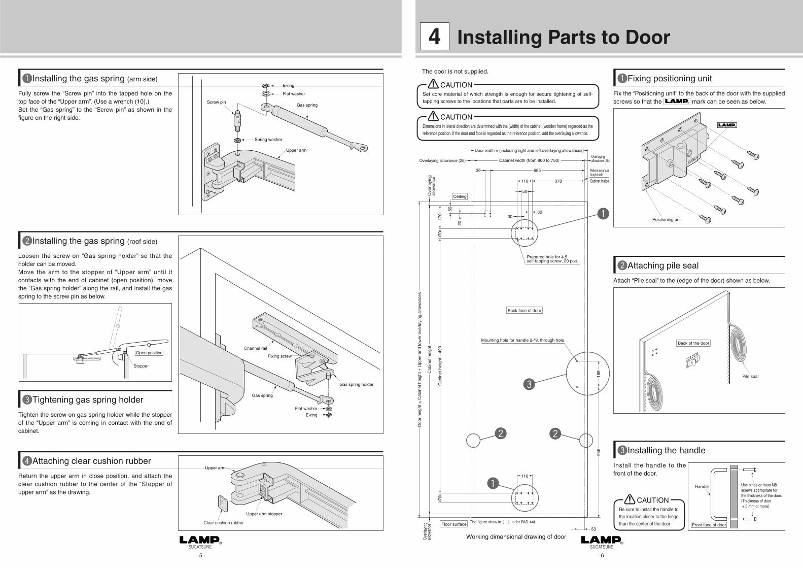
Fully screw the “Screw pin” into the tapped hole on the top face of the “Upper arm”. (Use a wrench (10).)Set the “Gas spring” to the “Screw pin” as shown in the figure on the right side.
Installing the gas spring (arm side)
5 6
Fix the “Positioning unit” to the back of the door with the supplied screws so that the mark can be seen as below.
Fixing positioning unit
Attach “Pile seal” to the (edge of the door) shown as below.
Attaching pile seal
Positioning unit
Pile seal
Back of the door
Install the handle to the front of the door.
Installing the handle
Handle Use binds or truss M8 screws appropriate for the thickness of the door.(Thickness of door + 5 mm or more)
Front face of door
E-ring
Spring washer
Upper arm
Screw pin
Flat washer
Gas spring
Ceiling
Floor surface
Working dimensional drawing of door
Back face of door
Reference of armhinged side
Cabinet inside
Mounting hole for handle 2-*9, through hole
Prepared hole for 4.5self-tapping screw, 20 pos.
59
30
188
946
Overlaying allowance (25)Overlayingallowance (25)Cabinet width (from 800 to 750)
70C
abin
et h
eigh
t – 4
9070
36 685
110 378
110
53
Door width = (including right and left overlaying allowances)
Doo
r he
ight
= C
abin
et h
eigh
t + U
pper
and
low
er o
verla
ying
allo
wan
ces
20
30
50
170
Cab
inet
hei
ght
Ove
rlayi
ngal
low
ance
Ove
rlayi
ngal
low
ance
Loosen the screw on “Gas spring holder” so that the holder can be moved.Move the arm to the stopper of “Upper arm” until it contacts with the end of cabinet (open position), move the “Gas spring holder” along the rail, and install the gas spring to the screw pin as below.
Installing the gas spring (roof side)
Fixing screw
Gas spring holder
Channel rail
Gas spring
Flat washer
E-ringTighten the screw on gas spring holder while the stopper of the “Upper arm” is coming in contact with the end of cabinet.
Tightening gas spring holder
Stopper
Open position
Return the upper arm in close position, and attach the clear cushion rubber to the center of the “Stopper of upper arm” as the drawing.
Attaching clear cushion rubber
Upper arm stopper
Upper arm
Clear cushion rubber
Installing Parts to Door4The door is not supplied.
Set core material of which strength is enough for secure tightening of self-tapping screws to the locations that parts are to be installed.
CAUTION
Dimensions in lateral direction are determined with the (width) of the cabinet (wooden frame) regarded as the reference position. If the door end face is regarded as the reference position, add the overlaying allowance.
CAUTION
Be sure to install the handle to the location closer to the hinge than the center of the door.
CAUTION
The figure show in [ ]is for FAD-44L
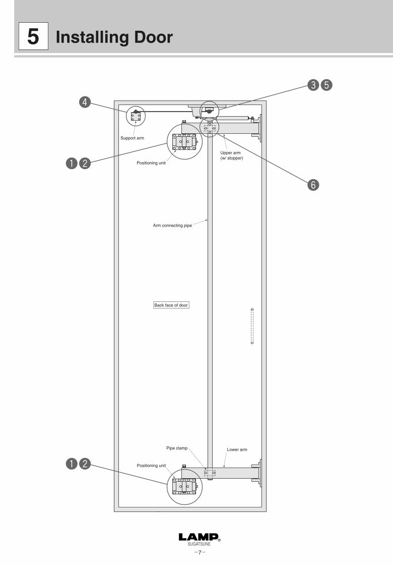
7
Support arm
Positioning unit
Pipe clamp
Positioning unit
Arm connecting pipe
Upper arm(w/ stopper)
Lower arm
Back face of door
Installing Door5

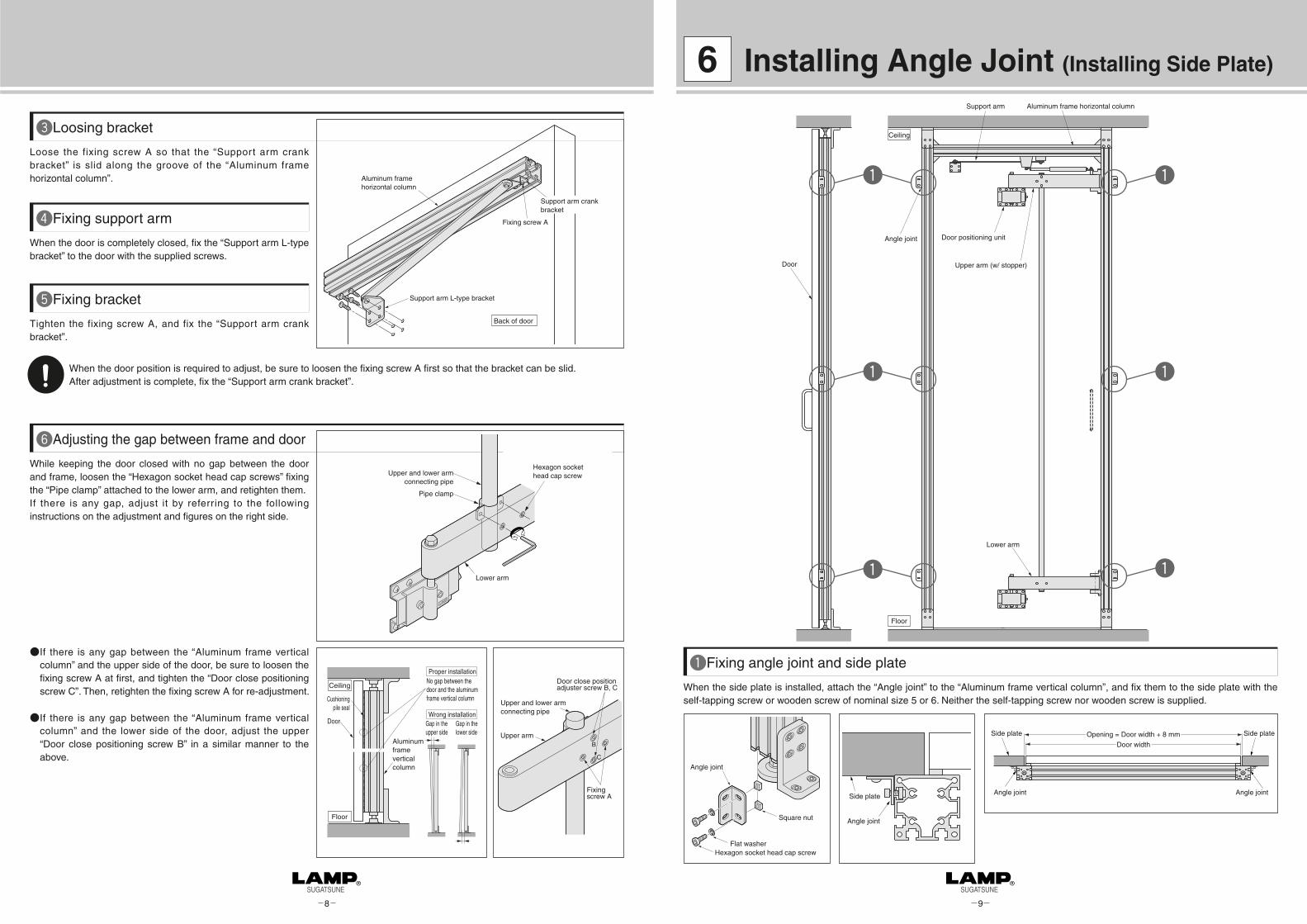
When the door is completely closed, fix the “Support arm L-type bracket” to the door with the supplied screws.
Fixing support arm
Tighten the fixing screw A, and fix the “Support arm crank bracket”.
Fixing bracket
Loosen the fixing screw A so that the “Support arm crank bracket” is slid along the groove of the “Channel rail”.
Loosing bracket
While keeping the door closed with no gap between the door and cabinet (wooden frame), loosen the “Hexagon socket head cap screws” fixing the “Pipe clamp” attached to the lower arm, and retighten them.If there is any gap, adjust it by referring to the following instructions on the adjustment and figures on the right side.
Adjusting the gap between cabinet (wooden frame) and door
8 9
When the door position is required to adjust, be sure to loosen the fixing screw A first so that the bracket can be slid.After adjustment is complete, fix the “Support arm crank bracket”.
● If there is any gap between the “Cabinet” and the upper side of the door, be sure to loosen the fixing screw A at first, and tighten the “Door close positioning screw C”. Then, retighten the fixing screw A for re-adjustment.
Connect the upper and lower arms to the “Positioning unit”.Insert hexagon head bolt with flat washer, then screw it by hexagon nut.
Connecting upper and lower arms to positioning unitHexagon head bolt for connecting
Flat washer
Arm
Positioning unit
Self-tapping screw
Hexagon nut
Adjust the vertical and horizontal positions after closing the door completely.Horizontal adjusting: Turn the screw A of the “Door positioning unit”
clockwise. Then, the door is moved leftward when it is seen from the back of the door. It is moved rightward when the screw A is turned counterclockwise.
Vertical adjusting: Turn the connecting hexagon head bolt clockwise.Then, the door is raised. It can be lowered when it is turned counterclockwise.
Vertical and horizontal positioning of door
Turn clockwiseAdjustment of door
Turn clockwise
Connecting hexagon head bolt Arm
Door Horizontal adjustment
Door
Vertical adjustment
Door positioning unit
Tighten this hexagon nut after vertical adjustment is complete.
When performing horizontal adjustment, turn them once to slacken them.After adjustment is complete, tighten them.
Screw A
Gap is not allowed
● If there is any gap between the “Cabinet” and the lower side of the door, adjust the upper “Door close positioning screw B” in a similar manner to the above.
Bottom of roof
Back of door
Support arm crank bracket
Channel rail
Fixing screw A
Support arm L-type bracket
Upper arm
Arm connecting pipe
Door close position adjuster screw B, C
B
C
Fixing screw A
Lower arm
Hexagon socket head cap screwArm connecting pipe
Pipe clamp
For both the upper and lower arms, gap should not be allowed between the head of the hexagon head bolt and the flat washer. If there is any gap, turn the hexagon head bolt clockwise to eliminate the gap so that the weight of the door is received by the upper and lower arms uniformly.
CAUTION

SUGATSUNE KOGYO CO., LTD.
Thank you very much for your purchase of our product. For safe and proper assembly, fully read this manual before installation.
Safety Cautions
Please follow these instructions carefully for proper use.
If you need to install this product, ask the dealer that you purchased our product or technicians who are skilled in the installation work of the product. Improper installation may lead to a fall of the product during usage, causing an extreme danger.
When installing the product, fully check the surface of the ceiling or floor, and securely fix with the proper anchor nuts and screws.Insufficient strength of the positions that the product is to be installed may lead to breakage of it, causing injury.
Notes on works
● Use your desired door.●Work on a clean floor to prevent any flaws or scratches on the aluminum frame flat surface.● After unpacking the product, check for damages on the parts.● DO NOT modify the product. Otherwise, its strength may be decreased.● Ask the technicians who are skilled in the installation work of the product for assembly or installation of the product.●When working on the product, be sure to observe the instructions in this manual.
Handling of product
1-8-11 HigashiKanda, Chiyoda-ku, Tokyo 101-8633, JapanTEL:+81-3-3866-2260 FAX:+81-3-3866-4447http://www.sugatsune.co.jpE-mail : [email protected]
For Overseas Customers
SUGATSUNE KOGYO CO., LTD.
ISO9001(JSAQ384) ISO14001(JSAE597) CERTIFICATE
221 East Selandia Lane,Carson,CA 90746,U.S.A.TEL:+1-310-329-6373 FAX:+1-310-329-0819TOLL FREE:(800) 562-5267 (from U.S.A & Canada only)http://www.sugatsune.comE-mail : [email protected]
For North American Customers
SUGATSUNE AMERICA, INC.
2010. 06 PRINTED IN JAPAN 0214-2
For your safety, be sure to read the following safety cautions first.
In addition,the following pictographs are used to indicate the types of warnings(cautions).
Indicates a matter which, if neglected, may cause loss of life or serious injuries.WARNINGIndicates a matter which, if neglected, may cause injuries or property damage.CAUTION
Indicates an act which you must not do. It is followed by specific content of the act.
Indicates an instruction which you must follow. It is followed by specific content of the
instruction.
Meanings of pictographs
Indicates a warning(caution) which you are required to take. It is followed by specific content
of the warning(caution).
PAT.P
Flat Door Hardware FAD-54,FAD-54LFlat Door Hardware FAD-54,FAD-54LInstruction ManualInstruction Manual
Aluminum Frame TypeAluminum Frame Type
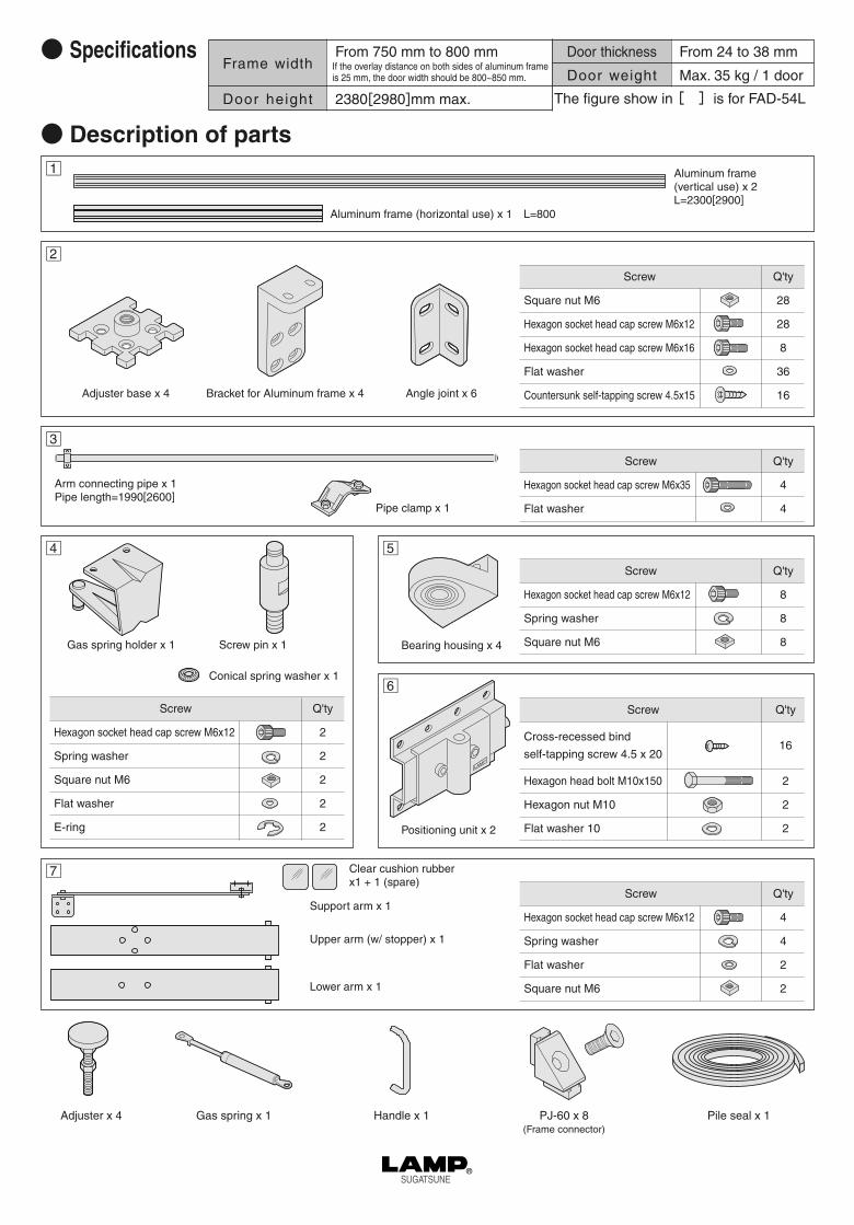
● SpecificationsFrame width
Door height
Door thickness
Door weight
From 750 mm to 800 mm
2380[2980]mm max.
From 24 to 38 mm
Max. 35 kg / 1 door
● Description of partsAluminum frame(vertical use) x 2L=2300[2900]
Aluminum frame (horizontal use) x 1 L=800
Adjuster base x 4 Bracket for Aluminum frame x 4 Angle joint x 6
Pipe clamp x 1
Screw
Hexagon socket head cap screw M6x35
Flat washer
Q'ty
4
4
Gas spring holder x 1 Screw pin x 1 Bearing housing x 4
Screw
Cross-recessed bind
self-tapping screw 4.5 x 20
Hexagon head bolt M10x150
Hexagon nut M10
Flat washer 10
Q'ty
16
2
2
2
Q'ty
2
2
2
2
2
Screw
Hexagon socket head cap screw M6x12
Spring washer
Square nut M6
Flat washer
E-ring
Clear cushion rubberx1 + 1 (spare)
Upper arm (w/ stopper) x 1
Lower arm x 1
Positioning unit x 2
□2
□3
□4
□7
□5
□6
□1
Screw
Hexagon socket head cap screw M6x12
Spring washer
Square nut M6
Q'ty
8
8
8
Screw
Hexagon socket head cap screw M6x12
Spring washer
Flat washer
Square nut M6
Q'ty
4
4
2
2
Screw
Square nut M6
Hexagon socket head cap screw M6x12
Hexagon socket head cap screw M6x16
Flat washer
Countersunk self-tapping screw 4.5x15
Q'ty
28
28
8
36
16
Arm connecting pipe x 1Pipe length=1990[2600]
Conical spring washer x 1
Support arm x 1
If the overlay distance on both sides of aluminum frame is 25 mm, the door width should be 800~850 mm.
The figure show in [ ]is for FAD-54L
Gas spring x 1 Handle x 1 PJ-60 x 8(Frame connector)
Pile seal x 1Adjuster x 4

Assembling Aluminum Frames 1
Installing the adjuster
Install the “Adjuster base” to the both ends of the “Aluminum frame vertical column” with the attached four countersunk head screws.Then, screw the “Adjuster” into the “Adjuster base”. Height of the adjuster on the floor side should be 50 mm from the floor surface. Fully screw in the adjuster on the ceiling side.
Adjuster
Adjuster base
Aluminum frame (vertical use)
Countersunk head screw
Ceiling
Screwing tighten
Floor
50 mm height
Temporarily fix the “Crank bracket for support arm” and “Gas spring holder” to the “Aluminum frame (horizontal use)”.
Installing bracket Aluminum frame (horizontal use)
Spring washer
Crank bracket for support arm
Gas spring mounting holder
Gas spring holder Crank bracket for aux. arm
Square nut
Pay close attention to the direction of the holder and the groove that the bracket is to be mounted.
CAUTION
Auxiliary arm
Fix the “Bearing housings” with the screws as shown in the figure below. For the mounting dimensions, see the figure shown on P.1. Temporarily fix the two housings located to the inner side of the upper and lower sets of the bearing housing.
Aluminum frame vertical column
Bearing housing
Spring washer
Square nut
Temporarily fix the two housings on the inner side
Temporarily fix the “Column fixing bracket” with the attached screws to the location shown on the figure on P.1 (upper and lower ends of aluminum frame).
Temporarily fix the “Auxiliary arm” with tape to the aluminum frame (horizontal use) so that it is not moved. (Tape is not enclosed.)
Flat washer
Column fixing bracket
Square nut
Flat washer
Column fixing bracket
Square nut
Fixed bearing housing Installing aluminum frame fixing bracket
Temporary fixing of auxiliary arm
Temporarily fix with tape
Completely assemble the “Aluminum frame (vertical use)” and “Aluminum frame (horizontal use)” into a gate with “PJ-60 (frame connector)”.
When assembling, pay close attention to prevent any gap in the joint of the aluminum frames.
Assembling aluminum frames
Outer joint
Inner joint
Inner joint
Screw
35
1
3
2
1 Fit the inner joints into the gaps of the aluminum frame.
2 Put the outer joints onto the inner joints.
3 Tighten with the screws.
Ex) If the ceiling height is 2300mm, the frame length is 2200 mm.
Cut the “Aluminum frame (vertical use)” to the length “Ceiling height - 100mm”. The maximum ceiling height is 2400 mm.
The figures shown in this manual are applicable to the left-side-opening type door (left-hinged type). For the right-side-opening type (right-hinged type), install the parts symmetrically.
Check the contents of packing. Anchors must be separately prepared.
■ Assembling aluminum frame
Symbols from 1to 8shown in the figure indicate the locations described below.
1 2
When assembling the aluminum frames, work on the floor, and orient the surface of the aluminum frame without groove downward.
Cutting aluminum frame (vertical use)
Cut the “Aluminum frame (horizontal use)” to the setup width (from 750 to 800mm).
Cutting aluminum frame (horizontal use)
Temporarily fix
Aluminum frame (vertical use)
Temporarily fix
Bearing housing (4 pcs.)
Adjuster (2 pcs.)
50
Aluminum frame (horizontal use)
Adjuster (2 pos.) PJ-60 Joint (8 pcs.)
Column fixing bracket
Floor
Ceiling
Alu
min
um fr
ame
leng
th =
Cei
ling
heig
ht -
100
Width from 750 to 800
Gas spring holder
Crank bracket for support arm
85
35
heig
ht to
cei
ling
- 41
419
86 m
ax.,
100
or m
ore
100
or m
ore
Alu
min
um c
olum
n le
ngth
= C
eilin
g he
ight
- 1
00
Alu
min
um c
olum
n m
axim
um le
ngth
230
0[29
00]
35
The figure show in [ ]is for FAD-54L

3
Fixing Aluminum Frame2
Insert the shaft of the “Upper arm (w/ stopper)” into the upper “Bearing housing”. Insert the temporarily fixed “Bearing housing” into the lower shaft of the arm, and securely fix.Insert the “Lower arm” in a same manner from the direction reverse to the above, and fix.
Cut the “Upper and lower arm connecting pipe” as shown on the figure below. Fit the “Upper and lower arm connecting pipe” to the recess of the “Upper arm”, and fix it with the attached screws. Fix the “Upper and lower arm connecting pipe” to the “Lower arm” with the “Pipe clamp” and the attached screw.
Installing upper and lower arms Installing upper and lower arm connecting pipe
Te m p o ra r i l y f i x t h e a s s e m bl e d aluminum frame with facing the surface without gap to the front side (door side) and extending the ceiling side adjuster.Then, fix the “Aluminum frame (vertical use)” with the “Alu-frame fixing bracket” to the ceiling surface and the floor surface with the screws.
Fixing aluminum frame to installing location
Bearing housing
Bearing housing
Vertical column
Lower arm
Shaft
Bearing housing
Bearing housing
Stopper
Upper arm
Shaft
Vertical column
Upper side Lower side
Aluminum framefixing bracket
Flat washer
Aluminum framefixing bracket
Flat washer
Ceiling
Extend the adjuster, and temporarily fix.
Wrench
Upper arm
Flat washer
Upper and lower arm connecting pipe
Upper and lower arm connecting pipe
Lower arm
Flat washer
Pipe clamp
When fixing the “Aluminum frame (vertical use) with the (Alu-frame) fixing bracket”, vertically fix the aluminum frame (vertical use) with a use of leveler or bubble leveler.
When installing the aluminum frame onto the concrete surface, put a M6 anchor nut, and fix with screws in 16 mm or more length.
When installing the aluminum frame onto the wooden or plywood surface, put a M6 insert nut, and fix with screws in 16 mm or more length or self-tapping screw or wooden screw of nominal size from 5 to 6. Use the screw with length that enough strength can be secured. (No anchor nut, insert nut, self-tapping screw, or wooden screw is attached.)
Pip
e le
ngth
= C
eilin
g he
ight
- 4
10
If the pipe is cut, insert the resin cap again.
Ensure that all the screws are securely tightened.
Aluminum frame fixing bracket Fixed bearing housing
Fixed bearing housing
Temporary fixed bearing housing
Upper arm(w/ stopper)
Temporary fixed bearing housing
Upper and lower arm connecting pipe
Lower arm
Ceiling
Floor
5050
Pip
e le
ngth
= C
eilin
g he
ight
- 4
10, 1
990[
2600
] max
. (re
sin
cap
is n
ot in
clud
ed)
Alu
min
um fr
ame
leng
th =
Cei
ling
heig
ht -
100
Alu
min
um fr
ame
max
. len
gth
2300
[ 290
0]
Upper side Lower side
The figure show in [ ]is for FAD-54L

4
Installing Gas Spring3
Upper arm (w/ stopper)
Gas spring holder
Ceiling
Floor

Install the “Gas spring” to the “Gas spring holder” as shown on the figure below.
Screw tightly the “Screw pin” into the screw hole on the top face of the “Upper arm”. (Use a wrench (10).)
Installing the gas spring (frame side)
loose the screw on “Gas spring holder” (see the figure (1)) so that the holder can be moved.Move the arm to the stopper of “Upper arm” until it contacts with the aluminum frame (open position), and install the gas spring to the screw pin as below.
Installing the gas spring (arm side)
Tighten the screw on gas spring holder (see the figure (1)) while the stopper of the “Upper arm” is coming in contact with the aluminum frame.
Tightening fixing screw
Return the upper arm in close position, and attach the clear cushion rubber to the center of the “Stopper of upper arm” as below.
Attaching clear cushion rubber
Screwing screw pin
5 6
Upper arm stopper
Upper Arm
Clear cushion rubber
Installing Parts to Door4
Fix the “Positioning unit” to the back of the door with the supplied screws so that the mark can be seen as below.
Fixing positioning unit
Attach “pile seal” to the (edge of the door) shown as below.
Attaching pile seal
Positioning unit
Back of the door
Pile seal
Install the handle to the front of the door.
Installing the handle
Handle
Front face of door
Use binds or truss M8 screws appropriate for the thickness of the door(Thickness of door + 5 mm or more)
The door is not supplied.
Gas spring holder
Rod side gas spring
Flat washer
E-ring
Screw pin
Spring washer
Upper arm
Screw hole
E-ring
Flat washer
Tube side gas spring
Screw pin
Upper arm
Ceiling
Back face of door
Floor surface
Working dimensional drawing of door
Reference ofarm hinged side
Overlaying allowance (25)
Overlaying allowance (25)
36
45
20
30
30
Door width = (including right and left overlaying allowances)
Frame width (from 800 to 750)
677
110 370
50
7028
7
176
Doo
r he
ight
- 5
30
Doo
r he
ight
= C
eilin
g he
ight
- 2
0 (I
f the
cei
ling
heig
ht is
230
0[30
00] ,
2280
[ 298
0])
110
70
188
946
Mounting hole for handle 2-φ 9, through hole
Prepared hole for 4.5 self-tapping screw, 20 pos.
Set core material of which strength is enough for secure tightening of self-tapping screws to the locations that parts are to be installed.
CAUTION
Dimensions in lateral direction are determined with the frame width. If the door end face is regarded as the reference position, add the overlaying allowance.
CAUTION
Stopper
Open position
Close position
Be sure to install the handle to the location closer to the hinge than the center of the door.
CAUTION
The figure show in [ ]is for FAD-54L

7
Installing Door5
Connect the upper and lower arms to the “Positioning unit”.Insert hexagon head bolt with flat washer, then secure it by hexagon nut.
Connecting upper and lower arms to positioning unit
Hexagon head bolt for connecting
Flat washer
Arm
Positioning unit
Self-tapping screw
Hexagon nut
Door
Door positioning unit
Support arm Aluminum frame horizontal column
Door positioning unit
Upper arm (w/ stopper)
Connecting pipe with upper + lower arm
Lower arm
Ceiling
Floor
Adjust the vertical and horizontal positions after closing the door completely.
Horizontal Adjusting: Turn the screw A of the “Door positioning unit” clockwise. Then, the door is moved leftward when it is seen from the back of the door. It is moved rightward when the screw A is turned counterclockwise.
Vertical Adjusting: Turn the connecting hexagon head bolt clockwise. Then, the door is raised. It can be lowered when it is turned counterclockwise.
Vertical and horizontal positioning of door
Turn clockwise
Longitudinal positioningAdjustment of door
Lateral positioning
Connecting hexagon head boltArm
Door
Door
Door positioning unit
Tighten this hexagon nut after longitudinal adjustment is complete.
When performing lateral adjustment, turn them once to slacken them.After adjustment is complete, tighten them.
Screw A
Gap is notallowed
For both the upper and lower arms, gap should not be allowed between the head of the hexagon head bolt and the flat washer. If there is any gap, turn the hexagon head bolt clockwise to eliminate the gap so that the weight of the door is received by the upper and lower arms uniformly.
CAUTION
When the door is completely closed, fix the “Support arm L-type bracket” to the door with the supplied screws.
Fixing support arm
Tighten the fixing screw A, and fix the “Support arm crank bracket”.
Fixing bracket
Loose the fixing screw A so that the “Support arm crank bracket” is slid along the groove of the “Aluminum frame horizontal column”.
Loosing bracket
While keeping the door closed with no gap between the door and frame, loosen the “Hexagon socket head cap screws” fixing the “Pipe clamp” attached to the lower arm, and retighten them.If there is any gap, adjust it by referring to the following instructions on the adjustment and figures on the right side.
Adjusting the gap between frame and door
Door
Cushioning pile seal
Aluminum frame vertical column
No gap between the door and the aluminum frame vertical column
Proper installation
Wrong installationGap in the upper side
Gap in the lower side
Ceiling
Floor
8 9
When the door position is required to adjust, be sure to loosen the fixing screw A first so that the bracket can be slid.After adjustment is complete, fix the “Support arm crank bracket”.
● If there is any gap between the “Aluminum frame vertical column” and the upper side of the door, be sure to loosen the fixing screw A at first, and tighten the “Door close positioning screw C”. Then, retighten the fixing screw A for re-adjustment.
● If there is any gap between the “Aluminum frame vertical column” and the lower side of the door, adjust the upper “Door close positioning screw B” in a similar manner to the above.
Installing Angle Joint (Installing Side Plate)6
When the side plate is installed, attach the “Angle joint” to the “Aluminum frame vertical column”, and fix them to the side plate with the self-tapping screw or wooden screw of nominal size 5 or 6. Neither the self-tapping screw nor wooden screw is supplied.
Fixing angle joint and side plate
Side plate Side plate
Angle jointAngle joint
Opening = Door width + 8 mm
Door width
Side plate
Angle joint
Angle joint
Hexagon socket head cap screw Flat washer
Square nut
Door
Support arm Aluminum frame horizontal column
Door positioning unit
Upper arm (w/ stopper)
Lower arm
Angle joint
Ceiling
Floor
Back of door
Fixing screw A
Support arm L-type bracket
Aluminum frame horizontal column
Support arm crank bracket
Upper arm
Upper and lower arm connecting pipe
B
C
Fixing screw A
Door close position adjuster screw B, C
Lower arm
Hexagon socket head cap screwUpper and lower arm
connecting pipe
Pipe clamp