safety design criteria (sdc) development for generation … · safety design criteria (sdc)...
TRANSCRIPT

Safety Design Criteria (SDC) Development for Generation-IV Sodium-cooled Fast
Reactor System
Ryodai Nakai and Tanju Sofu
GIF SDC Task Force
GIF Symposium 2015/ICONE23
Chiba
19 May 2015

Slide 1 GIF Symposium 2015/ICONE23, Chiba, Japan, 19 May 2015
Contents
• Introduction
– Background
– GIF’s Safety Goals & Basis for Safety Approach
• Safety Design Criteria (SDC) for Gen IV SFR
– SDC Phase 1 Report
– Status of International Reviews on the SDC Report
• Safety Design Guidelines (SDGs) Development
– Objectives and Current Status
• Concluding Remarks
Slide 2 GIF Symposium 2015/ICONE23, Chiba, Japan, 19 May 2015
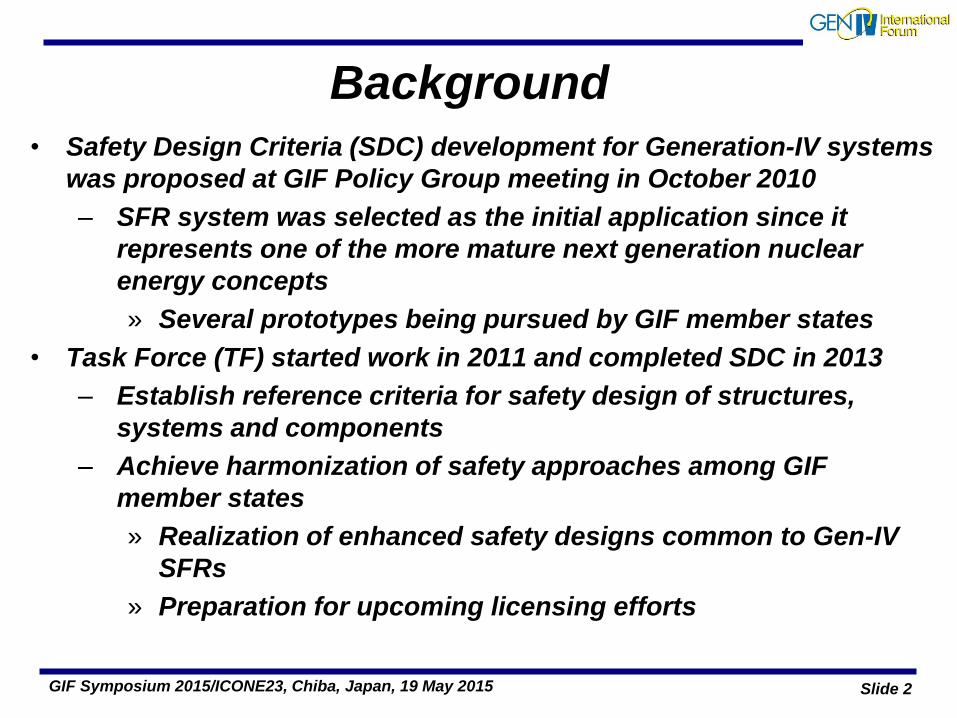
Background
• Safety Design Criteria (SDC) development for Generation-IV systems
was proposed at GIF Policy Group meeting in October 2010
– SFR system was selected as the initial application since it
represents one of the more mature next generation nuclear
energy concepts
» Several prototypes being pursued by GIF member states
• Task Force (TF) started work in 2011 and completed SDC in 2013
– Establish reference criteria for safety design of structures,
systems and components
– Achieve harmonization of safety approaches among GIF
member states
» Realization of enhanced safety designs common to Gen-IV
SFRs
» Preparation for upcoming licensing efforts

Slide 3 GIF Symposium 2015/ICONE23, Chiba, Japan, 19 May 2015
Hierarchy of Safety Standards
Safety Design Guideline
Domestic Codes & Standards

Slide 4 GIF Symposium 2015/ICONE23, Chiba, Japan, 19 May 2015
GIF’s Safety & Reliability Goals SR-1: Excel in Operational Safety and Reliability
Safety and reliability during normal operation, and likely kinds of operational events that set forced outage rate
SR-2: Very low likelihood & degree of reactor core damage
Minimizing frequency of initiating events, and design features for controlling & mitigating any initiating events w/o causing core damage
SR-3: Eliminate the need for offsite emergency response
Safety architecture to manage & mitigate severe plant conditions, for making small the possibility of releases of radiation
• Defence-in-depth
• A combination of deterministic and risk-informed safety
approach
• Safety to be built-in to the design, not added-on
• Emphasis on utilization of inherent and passive safety features
GIF’s Basic Safety Approach

Slide 5 GIF Symposium 2015/ICONE23, Chiba, Japan, 19 May 2015
SFR Design Tracks under GIF
JSFR
[Large Loop]
ESFR
[Large Pool]
KALIMER
[Pool]
SMFR
[Small Modular]

Slide 6 GIF Symposium 2015/ICONE23, Chiba, Japan, 19 May 2015
Safety Advantages of SFRs • Low pressure primary and intermediate coolant system
– Guard vessel and guard pipes to “maintain” coolant inventory
– No LOCA concern, no ECCS, no risk for control-rod ejection
• Liquid-metal coolant with excellent natural circulation
characteristics and a wide margin (~400 degC) to boiling
• Inherent safety with “net” negative reactivity feedback during
accidents that lead to elevated core/coolant temperatures
• Dedicated systems for decay heat removal to an ultimate heat sink
– Large difference between core outlet and inlet temperatures to
facilitate reliance on passive systems
• Low pressure (~0.5 bar) design pressure for containment (mostly
against heat from sodium fires)
• Much simpler operation and accident management (long grace
period for corrective action)

Slide 7 GIF Symposium 2015/ICONE23, Chiba, Japan, 19 May 2015
Challenges with SFRs
• High temperature (>500 degC core outlet temperature) and
high core power density
• Liquid sodium coolant that reacts with air, water and
concrete
– These reactions have to be prevented and/or mitigated
to avoid their effect on SSCs important to safety
• Fast reactor cores are not in their most reactive
configuration
– Relocation of core materials may lead to a hypothetical
core disruptive accident (HCDA)
• For large cores, sodium void worth can be positive
• Opaque sodium coolant could pose in-service inspection
and maintenance challenges

Slide 8 GIF Symposium 2015/ICONE23, Chiba, Japan, 19 May 2015
SFR Safety Principals
• Like LWRs, SFR safety is first based on utilization of multiple
redundant engineered protection systems to lower the probability
of accident occurrence and to limit its consequences:
– independent scram systems,
– multiple coolant pumps and heat transport loops, and
– multiple barriers to release of radioactive materials.
• SFR safety analyses traditionally focus on ATWS during which the
reactor scram system is assumed to fail.
– Because HCDAs could potentially result in re-criticalities.
– The safety design features that enhance inherent negative
reactivity feedback and passive decay heat removal
capabilities provide additional measures to prevent/mitigate
HCDAs even during these very low probability accidents.

Slide 9 GIF Symposium 2015/ICONE23, Chiba, Japan, 19 May 2015
Defence-in-depth (DiD) & Plant States
based on IAEA INSAG-12 & SSR-2/1

Slide 10 GIF Symposium 2015/ICONE23, Chiba, Japan, 19 May 2015
Basic Scheme to outline the SDC High level safety fundamentals, and safety design goals
GIF’s Goals for safety & reliability
Basis for safety approach for design & assessment
Requirements in SFR System Research Plan
1) Particular issues for SFR 2) Reference of SDC Structure
3) Lessons learned from Fukushima Dai-ichi NPPs accident
IAEA SSR 2/1 Management of safety in design
Principal technical requirement
General Plant design
Design of specific plant system
Characteristic of Sodium-cooled Fast Reactor Reactivity (void) … Sodium fire & Sodium-water reaction…
Consideration on Severe Accident Re-criticality during Core Disruptive Accident
High Temperature & Low pressure system Creep property, Leak-Before-Break… No LOCA and no need of ECCS…
Enhanced Safety Approach Passive system for shutdown & cooling
Common cause failure by external event Loss of power for longer period
Decay heat removal, Fuel pool cooling Containment function on spent fuel in the pool Preparing multiple AMs, e.t.c.
GIF SFR SDC

Table-Of-Contents of “SDC Phase 1 Report”*
1. INTRODUCTION
1.1 Background and Objectives
1.2 Principles of the SDC formulation
2. SAFETY APPROACH TO THE SFR
AS A GENERATION-IV REACTOR SYSTEM
2.1 GIF Safety Goals and Basic Safety Approach
2.2 Fundamental Orientations on Safety
2.3 Safety approach of the Generation-IV SFR systems
3. MANAGEMENT OF SAFETY IN DESIGN Criteria 1-3
4. PRINCIPAL TECHNICAL CRITERIA Criteria 4-12
5. GENERAL PLANT DESIGN
5.1 Design Basis Criteria 13-28
5.2 Design for Safe Operation over the Lifetime of the Plant Cri.29-31
5.3 Human Factors Criterion 32
5.4 Other Design Considerations Criteria 33-41
5.5 Safety Analysis Criterion 42
*SDC-TF/2013/01, May 1, 2013
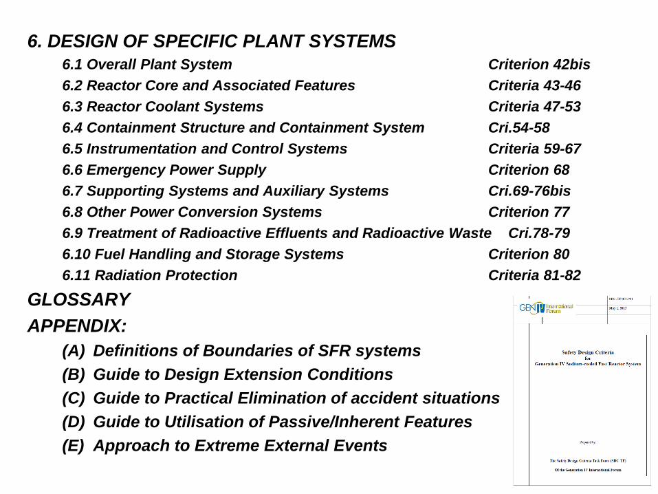
6. DESIGN OF SPECIFIC PLANT SYSTEMS
6.1 Overall Plant System Criterion 42bis
6.2 Reactor Core and Associated Features Criteria 43-46
6.3 Reactor Coolant Systems Criteria 47-53
6.4 Containment Structure and Containment System Cri.54-58
6.5 Instrumentation and Control Systems Criteria 59-67
6.6 Emergency Power Supply Criterion 68
6.7 Supporting Systems and Auxiliary Systems Cri.69-76bis
6.8 Other Power Conversion Systems Criterion 77
6.9 Treatment of Radioactive Effluents and Radioactive Waste Cri.78-79
6.10 Fuel Handling and Storage Systems Criterion 80
6.11 Radiation Protection Criteria 81-82
GLOSSARY
APPENDIX:
(A) Definitions of Boundaries of SFR systems
(B) Guide to Design Extension Conditions
(C) Guide to Practical Elimination of accident situations
(D) Guide to Utilisation of Passive/Inherent Features
(E) Approach to Extreme External Events
Slide 13 GIF Symposium 2015/ICONE23, Chiba, Japan, 19 May 2015
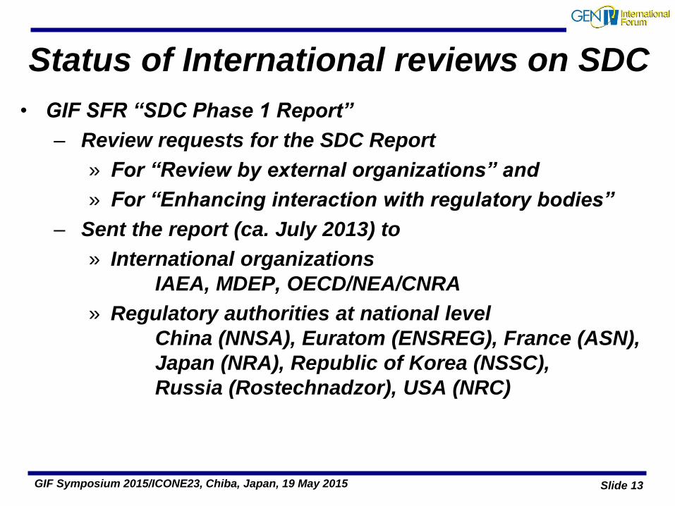
• GIF SFR “SDC Phase 1 Report”
– Review requests for the SDC Report
» For “Review by external organizations” and
» For “Enhancing interaction with regulatory bodies”
– Sent the report (ca. July 2013) to
» International organizations
IAEA, MDEP, OECD/NEA/CNRA
» Regulatory authorities at national level
China (NNSA), Euratom (ENSREG), France (ASN),
Japan (NRA), Republic of Korea (NSSC),
Russia (Rostechnadzor), USA (NRC)
Status of International reviews on SDC

Slide 14 GIF Symposium 2015/ICONE23, Chiba, Japan, 19 May 2015
• NRC (USA)
– Comprehensive & detailed review, with proposals (Jan. 2014)
– GIF SDC Task Force prepared the resolutions to incorporate
• NNSA (China)
– Review results (Oct. 2013 & Jan. 2014)
– GIF SDC TF resolution replied (Aug. 2014)
• IRSN (France)
– Comments on interim version at the GIF-IAEA Safety Workshop
(Feb. 2012), resolutions already included in Phase I report.
• IAEA
– General and technically specific reviews (April 2014)
– GIF SDC Task Force prepared the resolutions to incorporate
Status of international reviews on “SDC”
External feedbacks have been or are being incorporated

Slide 15 GIF Symposium 2015/ICONE23, Chiba, Japan, 19 May 2015
Safety Design Guidelines (SDG) Development
• Main objective
– to support practical application of SDC in design process
for improving safety in specific topical areas
» including use of inherent/passive safety features
» design measures for prevention and mitigation of
severe accidents.
– Initial topical areas are considered:
» Particular importance since a fast reactor core is
typically not in its most reactive configuration
» Quantification of key criteria for safety improvement
Slide 16 GIF Symposium 2015/ICONE23, Chiba, Japan, 19 May 2015
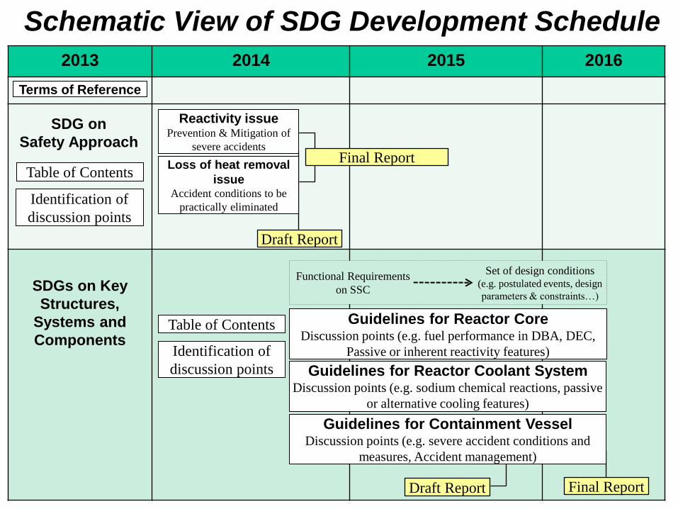
Schematic View of SDG Development Schedule
2013 2014 2015 2016
Terms of Reference
Table of Contents
Identification of
discussion points
SDGs on Key
Structures,
Systems and
Components
SDG on
Safety Approach
Identification of
discussion points
Table of Contents Guidelines for Reactor Core Discussion points (e.g. fuel performance in DBA, DEC,
Passive or inherent reactivity features)
Guidelines for Reactor Coolant System Discussion points (e.g. sodium chemical reactions, passive
or alternative cooling features)
Functional Requirements
on SSC
Set of design conditions (e.g. postulated events, design
parameters & constraints…)
Guidelines for Containment Vessel Discussion points (e.g. severe accident conditions and
measures, Accident management)
Draft Report
Loss of heat removal
issue Accident conditions to be
practically eliminated
Reactivity issue Prevention & Mitigation of
severe accidents Final Report
Draft Report Final Report

Slide 17 GIF Symposium 2015/ICONE23, Chiba, Japan, 19 May 2015
General Approach to Normal Operation, AOOs, and DBAs
General Approach to
Design Extension Conditions
• Normal Operation- Stable operation, with
controlling reactivity, temperature, flow…
• AOOs/DBAs- Shutdown the reactor and
maintain decay heat removal sufficient to keep
reactor core and system temperatures within
the applicable design limits.
• Prevention of Core Damage
Accident sequences typically caused by
failure of one or more systems
related to safety
Postulated initiating events more severe than those in DBA
• Mitigation of Core Damage
Mitigation of consequences of postulated accidents where significant core
damage may occur, with the objective of maintaining the containment
function to limit radioactive releases.
DiD
Level 1: Normal Operation
Level 2: AOO
Level 3: DBA
Level 4: DEC
Prevention of
Core Damage
Mitigation of Core
Damage
Level 5: Offsite Emergency Response

Slide 18 GIF Symposium 2015/ICONE23, Chiba, Japan, 19 May 2015
Exploiting SFR Characteristics to Enhance Safety
• Passive/Inherent safety for DEC
– On reactivity
» Inherent reactivity feedback to reduce the power as
core temperatures rise or
» Passive mechanism are applicable for shutdown
systems, such as SASS, HSR, and GEM
– On decay heat removal
» Natural circulation of single phase sodium coolant
» can be placed in different locations for enhancing
diversity
Slide 19 GIF Symposium 2015/ICONE23, Chiba, Japan, 19 May 2015
Exploiting SFR Characteristics to Enhance Safety
• In-Vessel Retention
– In the course of core degradation during unprotected
transients, measures should be provided to prevent
prompt criticality
– Reactor coolant boundary should maintain the
boundary function against pressure load including fuel-
coolant interaction
– Measures should be provided for ensuring long term
cooling of core materials inside the reactor vessel
under sub-critical condition

Slide 20 GIF Symposium 2015/ICONE23, Chiba, Japan, 19 May 2015
Practical Elimination of Accident Situations:
• Severe accidents with mechanical energy release higher
than the containment capability
– Power excursions for intact core situations
» Large gas flow through the core
» Large-scale core compaction
» Collapse of the core support structures
• Situations leading to the failure of the containment with
risk of fuel damage
– Complete loss of decay heat removal function that leads to
core damage and failure of primary coolant boundary
– Core uncovering due to sodium inventory loss
• Fuel degradation in fuel storage or during when the
containment may not be functional due to maintenance
– Core damage during maintenance
– Spent fuel melting in the storage

Slide 21 GIF Symposium 2015/ICONE23, Chiba, Japan, 19 May 2015
Design requirements on reactivity characteristics
Normal Operation, AOO, DBA, DEC w/o Core Damage
» Shall require inherent reactor power stability
» Reactor Shutdown System shall prevent sodium
boiling and maintain core coolable geometry
Design Extension Condition with Core Damage
» Shall prevent excessive insertion of reactivity by
coolant boiling, cladding and fuel relocation after
core damage

Slide 22 GIF Symposium 2015/ICONE23, Chiba, Japan, 19 May 2015
Quantification of requirement
on reactivity characteristics
• For Normal operation, AOO and DBA
» Power reactivity coefficient < 0 (Negative)
» Reactor shutdown capability with inherent feedback
> Postulated reactivity insertion
• For Design Extension Condition
» Before core damage: same as the requirement for DBA,
– Achieved by passive measures or inherent features
» After core damage:
– Total reactor core reactivity < 1$ (below prompt criticality)
» Sodium void worth can be positive as far as the above
conditions are satisfied.

Slide 23 GIF Symposium 2015/ICONE23, Chiba, Japan, 19 May 2015
Concluding Remarks • The “Safety Design Criteria Phase 1 Report”
– Issued by the GIF on May 2013
– Disseminated for international review to:
» International organizations
» National Regulatory Bodies
– Important feedbacks have been or are being incorporated:
» e.g. IAEA, IRSN, USNRC, NNSA …
• The “Safety Design Guidelines” development in Phase II
– Started from Sept. 2013
– Two Safety Design Guidelines (SDG):
» Safety Approach and Design Conditions SDG in final
drafting stage
» Key Structures, Systems and Components SDG

Slide 24 GIF Symposium 2015/ICONE23, Chiba, Japan, 19 May 2015
Thank you
for your attention !!

Status* Status* IAEA SSR 2/1 GIF SFR SDC Status* Status*Requirement # paragraph # Criterion # paragraph # M/A/D/U Requirement # paragraph # Criterion # paragraph # M/A/D/U Requirement # paragraph # Criterion # paragraph # M/A/D/U Requirement # paragraph # Criterion # paragraph # M/A/D/U
20 20 M 6. DESIGN OF SPECIFIC PLANT SYSTEMS INSTRUMENTATION AND CONTROL SYSTEMS
1 1 U 5.27 5.27 M OVERALL PLANT SYSTEM 60 60 U
3.1 3.1 M 5.28 5.28 U 42bis A 61 61 U
2 2 U 5.29 5.29 M REACTOR CORE AND ASSOCIATED FEATURES 6.32 6.32 M
3.2 3.2 U 5.30 5.30 U 43 43 M 6.33 6.33 U
3.3 3.3 M 5.31 5.31 M 6.1 6.1 M 62 62 U
3.4 3.4 M 5.32 5.32 M 6.2-6.3 6.2-6.3 U 6.34-6.36 6.34-6.36 U
3 3 U 21 21 U 44 44 M 63 63 U
3.5-3.6 3.5-3.6 U 5.33 5.33 U 6.3bis A 6.37 6.37 M
22 22 U 6.3ter A 64 64 U
4 4 M 5.34 5.34 M 6.3quater A 6.38 6.38 U
4.1-4.2 4.1-4.2 U 5.35-5.36 5.35-5.36 U 45 45 U 65 65 U
5 5 U 23 23 U 6.4 6.4 M 6.39-6.40 6.39-6.40 U
4.3-4.4 4.3-4.4 U 5.37-5.38 5.37-5.38 U 6.5 6.5 M 66 66 M
6 6 U 24 24 U 6.6 6.6 M 6.41 6.41 U
4.5-4.8 4.5-4.8 U 25 25 U 6.6bis A 67 67 U
7 7 M 5.39-5.40 5.39-5.40 U 46 46 M 6.42 6.42 U
4.9 4.9 M 26 26 U 6.7-6.8 6.7-6.8 U EMERGENCY POWER SUPPLY
4.10 4.10 U 5.41 5.41 U 6.9 6.9 M 68 68 U
4.11 4.11 M 27 27 U 6.10-6.12 6.10-6.12 U 6.43 6.43 M
4.12-4.13 4.12-4.13 U 5.42-5.43 5.42-5.43 U REACTOR COOLANT SYSTEMS 6.44 6.44 M
8 8 U 28 28 U 47 47 U 6.45 6.45 U
9 9 U 5.44 5.44 M 6.13 6.13 M SUPPORTING SYSTEMS AND AUXILIARY SYSTEMS
4.14-4.16 4.14-4.16 U DESIGN FOR SAFE OPERATION OVER THE LIFETIME OF THE PLANT 6.14 6.14 M 69 69 U
10 10 U 29 29 U 6.14bis A 70 70 U
4.17-4.18 4.17-4.18 U 5.45-5.47 5.45-5.47 U 6.14ter A 6.46 6.46 U
11 11 U 30 30 U 6.15 6.15 M 71 71 U
4.19 4.19 U 5.48-5.50 5.48-5.50 U 6.15bis A 6.47 6.47 U
12 12 M 31 31 M 6.15ter A 72 72 M
4.20 4.20 M 5.51-5.52 5.51-5.52 U 6.16 6.16 M 73 73 U
13 13 U HUMAN FACTORS 6.16bis A 6.48 6.48 M
5.1 5.1 M 32 32 U 6.16ter A 6.49 6.49 U
5.2 5.2 U 5.53-5.62 5.53-5.62 U 6.16quater A 74 74 M
5. GENERAL PLANT DESIGN OTHER DESIGN CONSIDERATIONS 6.16quinquies A 6.50 6.50 M
DESIGN BASIS 33 33 U 48 48 M 6.51-6.54 6.51-6.54 U
14 14 U 5.63 5.63 M 49 49 M 6.54bis A
5.3 5.3 U 34 34 M 50 50 M 6.54ter A
15 15 U 35 35 M 6.17 6.17 M 75 75 U
5.4 5.4 U 36 36 U 6.17bis A 76 76 U
16 16 U 5.64-5.65 5.64-5.65 U 51 51 M 6.55 6.55 U
5.5 5.5 M 37 37 U 52 D [incl. in #51] 76bis A
5.6-5.9 5.6-5.9 U 5.66-5.67 5.66-5.67 U 6.18 6.18 M OTHER POWER CONVERSION SYSTEMS
5.10 5.10 M 6.19 6.19 M 77 77 M
5.11-5.15 5.11-5.15 U 38 38 U 6.19bis A 6.56 6.56 M
17 17 U 5.68 5.68 U 53 53 M 6.57 6.57 M
5.16 5.16 M 39 39 U CONTAINMENT STRUCTURE AND CONTAINMENT SYSTEM 6.58 6.58 U
5.17 5.17 M 40 40 U 54 54 U TREATMENT OF RADIOACTIVE EFFLUENTS AND RADIOACTIVE WASTE
5.18 5.15bis M 5.69-5.70 5.69-5.70 U 55 55 U 78 78 M
5.18 A 41 41 U 6.20 6.20 M 6.59-6.60 6.59-6.60 U
5.19 5.19 M SAFETY ANALYSIS 6.21 6.21 M 79 79 M
5.20 5.20 M 42 42 U 56 56 M 6.61-6.63 6.61-6.63 U
5.21 5.21 M 5.71-5.74 5.71-5.74 U 6.22 6.22 M FUEL HANDLING AND STORAGE SYSTEMS
5.22 5.22 U 5.75 5.75 M 6.23 6.23 M
18 18 M 5.76 5.76 U 6.24 6.24 M 80 80 U
5.23 5.23 M 57 57 U 6.64-6.65 6.64-6.65 U
19 19 U 6.25-6.26 6.25-6.26 U 6.66 6.66 M
5.24-5.25 5.24-5.25 U 58 58 U 6.67 6.67 M
5.26 5.26 M 6.27 6.27 M 6.68 6.68 M
6.28 6.28 M 6.68bis A
*M: Modified A: Added D: Deleted U: Unchanged 6.29 6.29 M RADIATION PROTECTION
6.30 D 81 81 U
59 59 U 6.69 6.69 M
6.31 6.31 U 6.70-6.76 6.70-6.76 U
6.31bis A 82 82 M
6.77-6.84 6.77-6.84 U
3. MANAGEMENT OF SAFETY IN DESIGN
4. PRINCIPAL TECHNICAL CRITERIA
IAEA SSR 2/1 GIF SFR SDC IAEA SSR 2/1 GIF SFR SDC IAEA SSR 2/1 GIF SFR SDC
*M: Modified A: Added D: Deleted U: Unchanged
SDC Criteria (total 83): Modified 20, Added 2, Deleted 1, Un-changed 60
[Added: Overall Plant System & Sodium heating systems / Deleted: ECCS]
Difference between “GIF SDC Criteria” and “IAEA SSR 2/1 Requirements”
Status* Status* IAEA SSR 2/1 GIF SFR SDC Status* Status*Requirement # paragraph # Criterion # paragraph # M/A/D/U Requirement # paragraph # Criterion # paragraph # M/A/D/U Requirement # paragraph # Criterion # paragraph # M/A/D/U Requirement # paragraph # Criterion # paragraph # M/A/D/U
20 20 M 6. DESIGN OF SPECIFIC PLANT SYSTEMS INSTRUMENTATION AND CONTROL SYSTEMS
1 1 U 5.27 5.27 M OVERALL PLANT SYSTEM 60 60 U
3.1 3.1 M 5.28 5.28 U 42bis A 61 61 U
2 2 U 5.29 5.29 M REACTOR CORE AND ASSOCIATED FEATURES 6.32 6.32 M
3.2 3.2 U 5.30 5.30 U 43 43 M 6.33 6.33 U
3.3 3.3 M 5.31 5.31 M 6.1 6.1 M 62 62 U
3.4 3.4 M 5.32 5.32 M 6.2-6.3 6.2-6.3 U 6.34-6.36 6.34-6.36 U
3 3 U 21 21 U 44 44 M 63 63 U
3.5-3.6 3.5-3.6 U 5.33 5.33 U 6.3bis A 6.37 6.37 M
22 22 U 6.3ter A 64 64 U
4 4 M 5.34 5.34 M 6.3quater A 6.38 6.38 U
4.1-4.2 4.1-4.2 U 5.35-5.36 5.35-5.36 U 45 45 U 65 65 U
5 5 U 23 23 U 6.4 6.4 M 6.39-6.40 6.39-6.40 U
4.3-4.4 4.3-4.4 U 5.37-5.38 5.37-5.38 U 6.5 6.5 M 66 66 M
6 6 U 24 24 U 6.6 6.6 M 6.41 6.41 U
4.5-4.8 4.5-4.8 U 25 25 U 6.6bis A 67 67 U
7 7 M 5.39-5.40 5.39-5.40 U 46 46 M 6.42 6.42 U
4.9 4.9 M 26 26 U 6.7-6.8 6.7-6.8 U EMERGENCY POWER SUPPLY
4.10 4.10 U 5.41 5.41 U 6.9 6.9 M 68 68 U
4.11 4.11 M 27 27 U 6.10-6.12 6.10-6.12 U 6.43 6.43 M
4.12-4.13 4.12-4.13 U 5.42-5.43 5.42-5.43 U REACTOR COOLANT SYSTEMS 6.44 6.44 M
8 8 U 28 28 U 47 47 U 6.45 6.45 U
9 9 U 5.44 5.44 M 6.13 6.13 M SUPPORTING SYSTEMS AND AUXILIARY SYSTEMS
4.14-4.16 4.14-4.16 U DESIGN FOR SAFE OPERATION OVER THE LIFETIME OF THE PLANT 6.14 6.14 M 69 69 U
10 10 U 29 29 U 6.14bis A 70 70 U
4.17-4.18 4.17-4.18 U 5.45-5.47 5.45-5.47 U 6.14ter A 6.46 6.46 U
11 11 U 30 30 U 6.15 6.15 M 71 71 U
4.19 4.19 U 5.48-5.50 5.48-5.50 U 6.15bis A 6.47 6.47 U
12 12 M 31 31 M 6.15ter A 72 72 M
4.20 4.20 M 5.51-5.52 5.51-5.52 U 6.16 6.16 M 73 73 U
13 13 U HUMAN FACTORS 6.16bis A 6.48 6.48 M
5.1 5.1 M 32 32 U 6.16ter A 6.49 6.49 U
5.2 5.2 U 5.53-5.62 5.53-5.62 U 6.16quater A 74 74 M
5. GENERAL PLANT DESIGN OTHER DESIGN CONSIDERATIONS 6.16quinquies A 6.50 6.50 M
DESIGN BASIS 33 33 U 48 48 M 6.51-6.54 6.51-6.54 U
14 14 U 5.63 5.63 M 49 49 M 6.54bis A
5.3 5.3 U 34 34 M 50 50 M 6.54ter A
15 15 U 35 35 M 6.17 6.17 M 75 75 U
5.4 5.4 U 36 36 U 6.17bis A 76 76 U
16 16 U 5.64-5.65 5.64-5.65 U 51 51 M 6.55 6.55 U
5.5 5.5 M 37 37 U 52 D [incl. in #51] 76bis A
5.6-5.9 5.6-5.9 U 5.66-5.67 5.66-5.67 U 6.18 6.18 M OTHER POWER CONVERSION SYSTEMS
5.10 5.10 M 6.19 6.19 M 77 77 M
5.11-5.15 5.11-5.15 U 38 38 U 6.19bis A 6.56 6.56 M
17 17 U 5.68 5.68 U 53 53 M 6.57 6.57 M
5.16 5.16 M 39 39 U CONTAINMENT STRUCTURE AND CONTAINMENT SYSTEM 6.58 6.58 U
5.17 5.17 M 40 40 U 54 54 U TREATMENT OF RADIOACTIVE EFFLUENTS AND RADIOACTIVE WASTE
5.18 5.15bis M 5.69-5.70 5.69-5.70 U 55 55 U 78 78 M
5.18 A 41 41 U 6.20 6.20 M 6.59-6.60 6.59-6.60 U
5.19 5.19 M SAFETY ANALYSIS 6.21 6.21 M 79 79 M
5.20 5.20 M 42 42 U 56 56 M 6.61-6.63 6.61-6.63 U
5.21 5.21 M 5.71-5.74 5.71-5.74 U 6.22 6.22 M FUEL HANDLING AND STORAGE SYSTEMS
5.22 5.22 U 5.75 5.75 M 6.23 6.23 M
18 18 M 5.76 5.76 U 6.24 6.24 M 80 80 U
5.23 5.23 M 57 57 U 6.64-6.65 6.64-6.65 U
19 19 U 6.25-6.26 6.25-6.26 U 6.66 6.66 M
5.24-5.25 5.24-5.25 U 58 58 U 6.67 6.67 M
5.26 5.26 M 6.27 6.27 M 6.68 6.68 M
6.28 6.28 M 6.68bis A
*M: Modified A: Added D: Deleted U: Unchanged 6.29 6.29 M RADIATION PROTECTION
6.30 D 81 81 U
59 59 U 6.69 6.69 M
6.31 6.31 U 6.70-6.76 6.70-6.76 U
6.31bis A 82 82 M
6.77-6.84 6.77-6.84 U
3. MANAGEMENT OF SAFETY IN DESIGN
4. PRINCIPAL TECHNICAL CRITERIA
IAEA SSR 2/1 GIF SFR SDC IAEA SSR 2/1 GIF SFR SDC IAEA SSR 2/1 GIF SFR SDC
Example: