safety hazards material processing laboratory room 232 · safety hazards material processing...
TRANSCRIPT
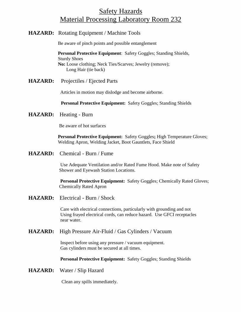
Safety Hazards
Material Processing Laboratory Room 232
HAZARD: Rotating Equipment / Machine Tools
Be aware of pinch points and possible entanglement
Personal Protective Equipment: Safety Goggles; Standing Shields,
Sturdy Shoes
No: Loose clothing; Neck Ties/Scarves; Jewelry (remove);
Long Hair (tie back)
HAZARD: Projectiles / Ejected Parts
Articles in motion may dislodge and become airborne.
Personal Protective Equipment: Safety Goggles; Standing Shields
HAZARD: Heating - Burn
Be aware of hot surfaces
Personal Protective Equipment: Safety Goggles; High Temperature Gloves;
Welding Apron, Welding Jacket, Boot Gauntlets, Face Shield
HAZARD: Chemical - Burn / Fume
Use Adequate Ventilation and/or Rated Fume Hood. Make note of Safety
Shower and Eyewash Station Locations.
Personal Protective Equipment: Safety Goggles; Chemically Rated Gloves;
Chemically Rated Apron
HAZARD: Electrical - Burn / Shock
Care with electrical connections, particularly with grounding and not
Using frayed electrical cords, can reduce hazard. Use GFCI receptacles
near water.
HAZARD: High Pressure Air-Fluid / Gas Cylinders / Vacuum Inspect before using any pressure / vacuum equipment.
Gas cylinders must be secured at all times.
Personal Protective Equipment: Safety Goggles; Standing Shields
HAZARD: Water / Slip Hazard
Clean any spills immediately.
R. Dubrovsky Mechanical Engineering Department, NJIT ME 215, Engineering Materials & Processes Experiment # 3
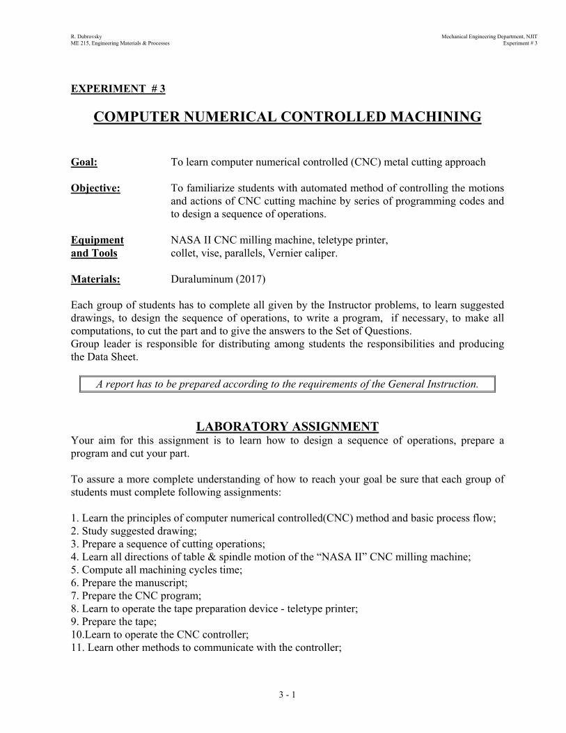
EXPERIMENT # 3
COMPUTER NUMERICAL CONTROLLED MACHINING Goal: To learn computer numerical controlled (CNC) metal cutting approach Objective: To familiarize students with automated method of controlling the motions
and actions of CNC cutting machine by series of programming codes and to design a sequence of operations.
Equipment NASA II CNC milling machine, teletype printer, and Tools collet, vise, parallels, Vernier caliper. Materials: Duraluminum (2017) Each group of students has to complete all given by the Instructor problems, to learn suggested drawings, to design the sequence of operations, to write a program, if necessary, to make all computations, to cut the part and to give the answers to the Set of Questions. Group leader is responsible for distributing among students the responsibilities and producing the Data Sheet.
A report has to be prepared according to the requirements of the General Instruction.
LABORATORY ASSIGNMENT Your aim for this assignment is to learn how to design a sequence of operations, prepare a program and cut your part. To assure a more complete understanding of how to reach your goal be sure that each group of students must complete following assignments: 1. Learn the principles of computer numerical controlled(CNC) method and basic process flow; 2. Study suggested drawing; 3. Prepare a sequence of cutting operations; 4. Learn all directions of table & spindle motion of the “NASA II” CNC milling machine; 5. Compute all machining cycles time; 6. Prepare the manuscript; 7. Prepare the CNC program; 8. Learn to operate the tape preparation device - teletype printer; 9. Prepare the tape; 10.Learn to operate the CNC controller; 11. Learn other methods to communicate with the controller;
3 - 1

R. Dubrovsky Mechanical Engineering Department, NJIT ME 215, Engineering Materials & Processes Experiment # 3
12.Execute your program without part cutting. Use “Single Block Mode” and “Automatic Mode” to check the CNC program;
13.Execute your program using “Single Block Mode” to perform 1/3 depth of cutting; 14.Execute your program using “Automatic Mode” to perform another 1/3 depth of cutting; 15.Finish your part by operating the cutting machine in “Automatic Mode” and cut your part to
the full depth.
ATTENTION
All final steps of your assignments must be checked and approved by the Instructor.
RULES FOR CLEAN UP: 1. All tools must be put in their proper place or returned to the Instructor. 2. All machinery must be cleaned and chips be swept into a pile near the aisle and placed in the
proper receptacle. In carrying out your assignment, follow the sequence given below:
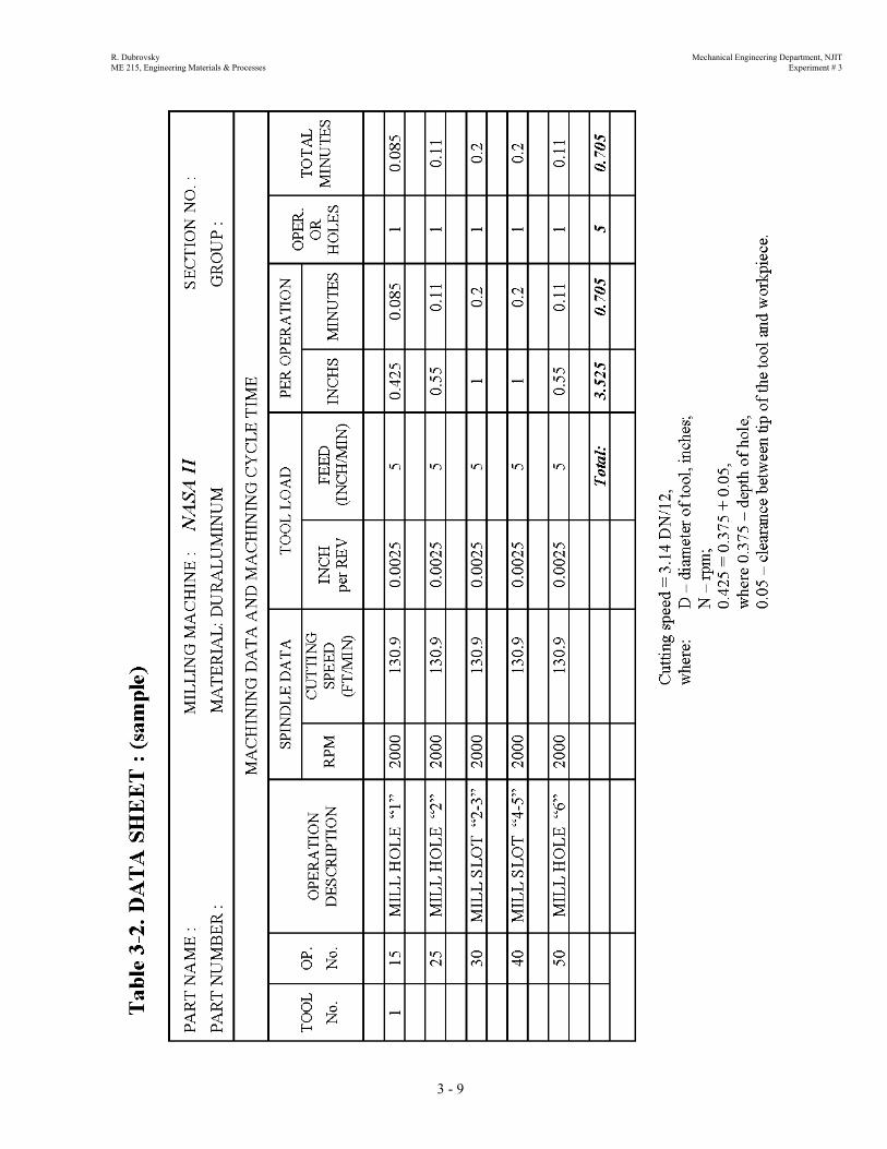
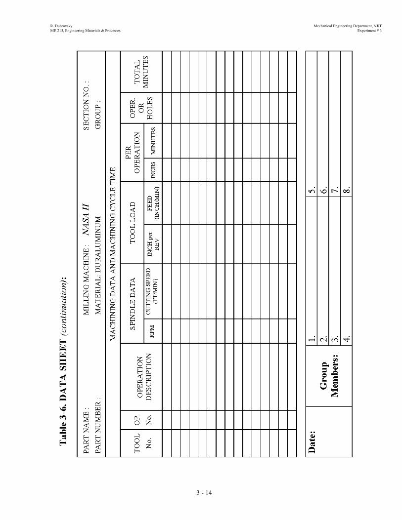
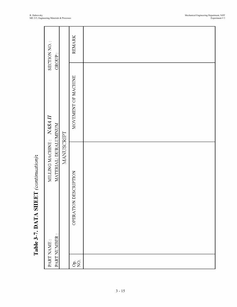
WEEK I 1. Learn the principles of CNC programming; 2. Learn the Binary Code of Decimal System shown on Fig. 3-?; 3. Consider the suggested drawing for your group, Fig. 3-?; 4. Plan the sequence of operations. Fill your plan in the Data Sheet, Table 3-? ; 5. Calculate and fill in all required data in the form “MACHINING DATA AND
MACHINING CYCLE TIME”, Table 3-? for your part with the help of the example in Table 3-?;
6. Prepare the manuscript in accordance with your sequence of operations for the movement of table and cutting tool. Use the Data Sheet on Fig. 3-?;
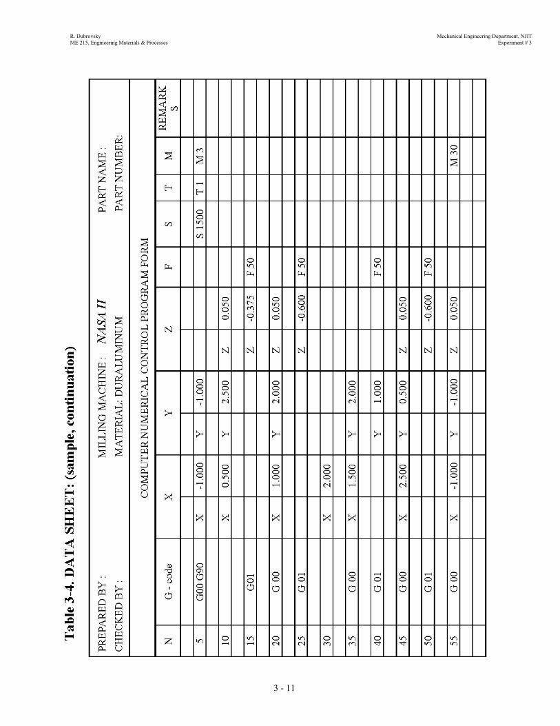
7. Prepare your CNC program using the form “COMPUTER NUMERICAL CONTROL PROGRAM” shown in Table 3-?;
8. Learn to operate the teletype printer and prepare the tape of your CNC program; 9. Prepare the duplicate of your tape by running it through tape duplicator; 10. Put all group member names on your program sheet, sign it and obtain the Instructor’s
approval.
ATTENTION
Your manuscript and CNC program must be checked and signed by the Instructor.
3 - 2

R. Dubrovsky Mechanical Engineering Department, NJIT ME 215, Engineering Materials & Processes Experiment # 3
WEEK II 1. Obtain the duraluminum blank from the Instructor and install it in the vise with the
assistance of the Instructor; 5. Learn the function and operation of the controller of “NASA II” CNC machine; 6. Learn different methods to upload and download CNC program into and from the
controller; 7. Learn accuracy of the cutting machine; 8. Learn how to set reference origin points; 9. Select & establish your part origin points; 10. Compare your program with the program memorized by CNC controller; 11. Define the reason why machine is not able to execute the maximum accuracy; 12. Check the CNC program by executing without cutting the CNC program using “Single
Block and Automatic Mode” and by lowering the table downward 5 turns; 13. Bring the table up by 4 turns of the crank, perform 1/3 depth cut of your part by
execution of prepared CNC program in “Single Block Mode”; 14. Execute your program and cut second 1/3 of the total depth using CNC program in
“Automatic Mode”, bring the table up by half turn more; 15. Bring the table up to the initial height and execute the CNC program using “Automatic
Mode” to perform full depth cutting process; 16. Take the duraluminum work out of the vise (after machine has come to a full stop).
Examine the finished part. 17. Discuss the operation procedures, results, repeatability and alternatives; 18. How to perform your part in large quantities? 19. Clean the machine and working area around the machine.
ATTENTION
Goggles must be worn when machine is operating.
3 - 3
R. Dubrovsky Mechanical Engineering Department, NJIT ME 215, Engineering Materials & Processes Experiment # 3
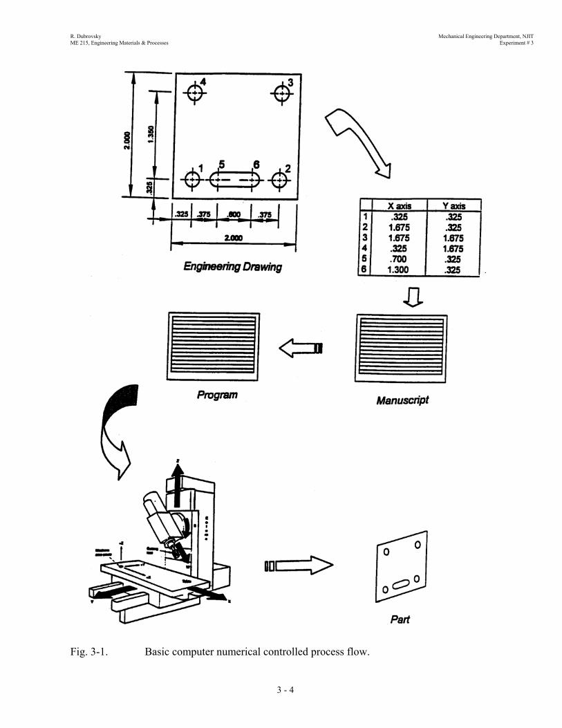
Fig
3 - 4
. 3-1. Basic computer numerical controlled process flow.

R. Dubrovsky Mechanical Engineering Department, NJIT ME 215, Engineering Materials & Processes Experiment # 3
Fig. 3-
2. Binary numbers & binary coded decimals3 - 5

R. Dubrovsky Mechanical Engineering Department, NJIT ME 215, Engineering Materials & Processes Experiment # 3
CNC Program Entries and Command Codes: 1. Line Number Letter Address: N Range: N0 to N19999 2. Feed rate Letter Address: F Range: IPM ( inch per minute ): F2 to F320 in increments of 0.1 IPM MMPM ( mm per minute ): F5 to F812 in increments of 1 MMPM Note: If a value greater than 320 is given, the feed will be set at F320. 3. Tool Number Letter Address: T Range: T1 to T 24 4. Miscellaneous Function Code: M Maximum number of digits: 2 Functions relative to direct machine movements and actions.
Code Before With After Modal Non-Modal Function M00 x x Program Stop M01 x x Optional Stop M03 x x Rotating Spindle M06 x x x Tool Change M25 x Z Axis Home M30 End of Program and
Back to Beginning
3 - 6
R. Dubrovsky Mechanical Engineering Department, NJIT ME 215, Engineering Materials & Processes Experiment # 3
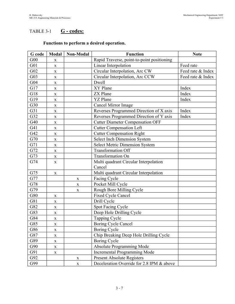
TABLE 3-1 G - codes: Functions to perform a desired operation. G code Modal Non-Modal Function Note G00 x Rapid Traverse, point-to-point positioning G01 x Linear Interpolation Feed rate G02 x Circular Interpolation, Arc CW Feed rate & Index G03 x Circular Interpolation, Arc CCW Feed rate & Index G04 x Dwell G17 x XY Plane Index G18 x ZX Plane Index G19 x YZ Plane Index G30 x Cancel Mirror Image G31 x Reverses Programmed Direction of X axis Index G32 x Reverses Programmed Direction of Y axis Index G40 x Cutter Diameter Compensation OFF G41 x Cutter Compensation Left G42 x Cutter Compensation Right G70 x Select Inch Dimension System G71 x Select Metric Dimension System G72 x Transformation Off G73 x Transformation On G74 x Multi quadrant Circular Interpolation
Cancel
G75 x Multi quadrant Circular Interpolation G77 x Facing Cycle G78 x Pocket Mill Cycle G79 x Rough Bore Milling Cycle G80 x Fixed Cycle Cancel G81 x Drill Cycle G82 x Spot Facing Cycle G83 x Deep Hole Drilling Cycle G84 x Tapping Cycle G85 x Boring Cycle Cancel G86 x Boring Cycle G87 x Chip Breaking Deep Hole Drilling Cycle G89 x Boring Cycle G90 x Absolute Programming Mode G91 x Incremental Programming Mode G92 x Present Absolute Registers G99 x Deceleration Override for 2.8 IPM & above
3 - 7

R. Dubrovsky Mechanical Engineering Department, NJIT ME 215, Engineering Materials & Processes Experiment # 3
Fig. 3-3. Part drawings
3 - 8
R. Dubrovsky Mechanical Engineering Department, NJIT ME 215, Engineering Materials & Processes Experiment # 3
3 - 9
R. Dubrovsky Mechanical Engineering Department, NJIT ME 215, Engineering Materials & Processes Experiment # 3
3 - 10
R. Dubrovsky Mechanical Engineering Department, NJIT ME 215, Engineering Materials & Processes Experiment # 3
3 - 11
R. Dubrovsky Mechanical Engineering Department, NJIT ME 215, Engineering Materials & Processes Experiment # 3
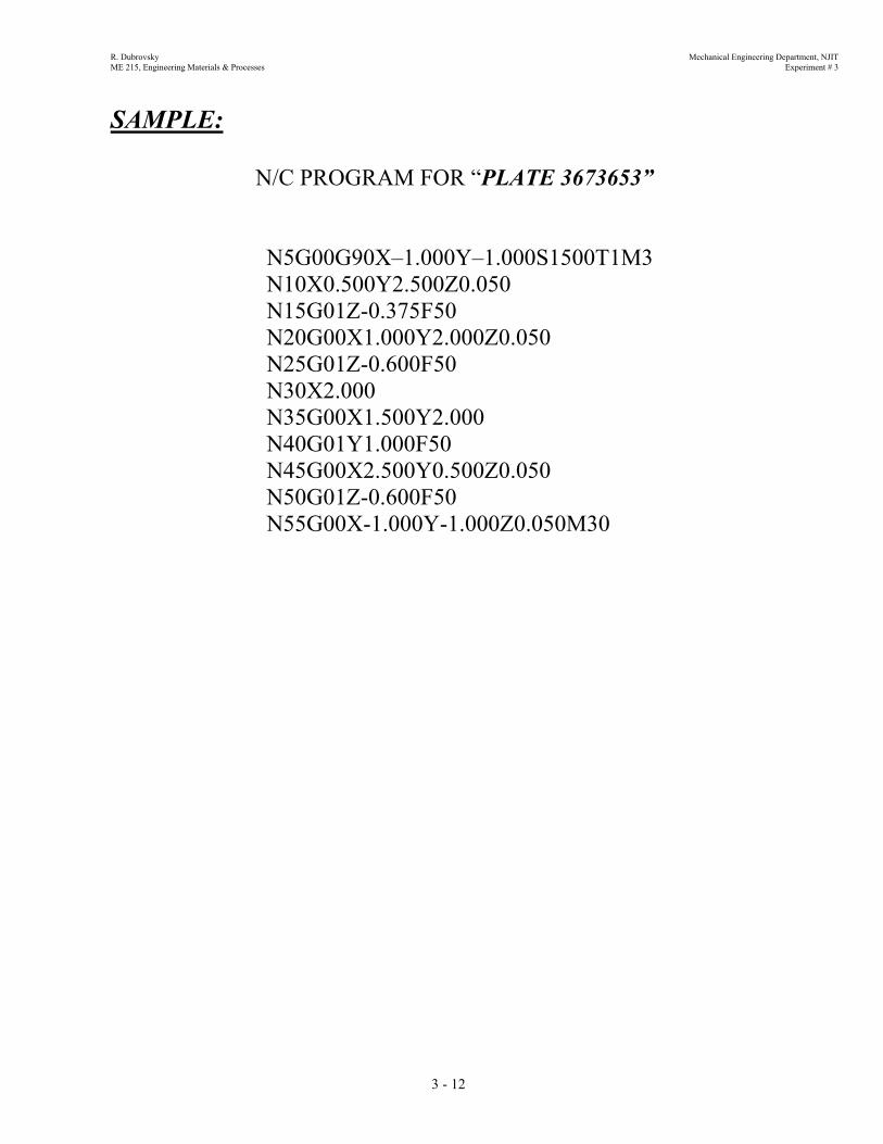
SAMPLE:
N/C PROGRAM FOR “PLATE 3673653”
N5G00G90X–1.000Y–1.000S1500T1M3 N10X0.500Y2.500Z0.050 N15G01Z-0.375F50 N20G00X1.000Y2.000Z0.050 N25G01Z-0.600F50
N30X2.000 N35G00X1.500Y2.000 N40G01Y1.000F50 N45G00X2.500Y0.500Z0.050 N50G01Z-0.600F50 N55G00X-1.000Y-1.000Z0.050M30
3 - 12

R. Dubrovsky Mechanical Engineering Department, NJIT ME 215, Engineering Materials & Processes Experiment # 3 R. Dubrovsky Mechanical Engineering Department, NJIT ME 215, Engineering Materials & Processes Experiment # 3
3 - 13
3 - 13
R. Dubrovsky Mechanical Engineering Department, NJIT ME 215, Engineering Materials & Processes Experiment # 3
3 - 14
R. Dubrovsky Mechanical Engineering Department, NJIT ME 215, Engineering Materials & Processes Experiment # 3
3 - 15

R. Dubrovsky Mechanical Engineering Department, NJIT ME 215, Engineering Materials & Processes Experiment # 3 R. Dubrovsky Mechanical Engineering Department, NJIT ME 215, Engineering Materials & Processes Experiment # 3
3 - 16
3 - 16

R. Dubrovsky Mechanical Engineering Department, NJIT ME 215, Engineering Materials & Processes Experiment # 3
SET OF QUESTIONS: 1. Explain the difference between Numerical Control & Computer Numerical Control. 2. What is the first step in preparing the program on N/C machine? 3. Convert the following Decimal numbers to Binary numbers:
a) 23; b) 92; c) 147; d) 1897 4. Position the tool to cut the hole shown in the figure below, use 3 axis x,y,z motion.
5. Calculate the cutting speed and machining time for all your cutting operation and fill in the
form called “Machining Data & Machining Cycle Time”, see Tab. 3-5 6. Write the instruction for positioning in absolute mode for spot drilling using the spot face
cycle. The depth of drilling is 0.195 and the feed rate is 10 inch per minute. 7. Determine the decimal value of the following binary number:
(1011)2 = (?) 10
8. What do the following expressions mean?
a) N100 G01 G 81 Z-1.50 F200 b) N55 G00 G91 X0Y0M3
9. Why is the air compressor needed with the Numerical Controlled Milling Machine NASA II?
3 - 17

R. Dubrovsky Mechanical Engineering Department, NJIT ME 215, Engineering Materials & Processes Experiment # 3
SUGGESTED LITERATURE:
1. E. P. De Garmo, J. Temple Black, Ronald A. Kosher, Materials and Processes in
Manufacturing, Macmillan, 8-th Edition, New York, 1997 2. L.E. Doyle, Manufacturing Processes and Materials for Engineers, Prentice-Hall, Inc., Third
Edition, Englewood, 1980 3. S. Kalpakjian, Manufacturing Processes for Engineering Materials, Addison-Wesley
Publishing Co., Reading, Massachusetts, 1990. 4. F.T. Farago, Handbook of Dimensional Measurement, Industrial Press, New York, 1978. 5. J. Pusztai, M. Sava, Computer Numerical Control, Reston Publishing Co., Inc., Reston,
Virginia, 1985 6. R.Dubrovsky. Laboratory Manual, Engineering Materials & Processes, ME Department,
NJIT, CAPCO, Oklahoma, 1998.
3 - 18