safety inspection and testing of lifting...
TRANSCRIPT
* TB 43-0142
TECHNICAL BULLETIN
SAFETY INSPECTION AND TESTINGOF LIFTING DEVICES
l This technical bulletin supersedes TB 43-0142, dated 30 August 1993, including all changes.
DISTRIBUTION STATEMENT A: Approved for public release; distribution is unlimited.
HEADQUARTERS, DEPARTMENT OF THE ARMY28 FEBRUARY 1997


*TB 43-0142
DEPARTMENT OF THE ARMY TECHNICAL BULLETIN
TECHNICAL BULLETIN
SAFETY INSPECTION AND TESTING OF LIFTING DEVICES
Headquarters, Department of the Army, Washington, DC28 February 1997
REPORTING ERRORS AND RECOMMENDING IMPROVEMENTS
You can help improve this manual. If you find any mistakes, or if you know of a way to improvethese procedures, please let us know. Mail your letter or DA Form 2028 (RecommendedChanges to Publications and Blank Forms), or DA Form 2028-2 located in the back of thismanual directly to: Commander, US Army Aviation and Troop Command, ATTN: AMSAT-I-MP,4300 Goodfellow Blvd., St. Louis, MO 63120-1798. You may also submit your recommendedchanges by E-mail directly to <mpmt%[email protected]>. A reply will befurnished directly to you. Instructions for sending an electronic 2028 may be found at the backof this manual immediately preceding the hard copy 2028.
DISTRIBUTION STATEMENT A: Approved for public release; distribution is unlimited.
TABLE OF CONTENTS
Paragraph Page
Purpose . . . . . . . . . . . . . . . . . . . . . . . . . . . . . . . . . . . . . . . . . . . . . 1 . . . . . . . 2
Scope . . . . . . . . . . . . . . . . . . . . . . . . . . . . . . . . . . . . . . . . . . . . . . . 2 . . . . . . . 2
Definitions . . . . . . . . . . . . . . . . . . . . . . . . . . . . . . . . . . . . . . . . . . . 3 . . . . . . . 2
Requirements . . . . . . . . . . . . . . . . . . . . . . . . . . . . . . . . . . . . . . . . 4 . . . . . . . 3
Responsibilities . . . . . . . . . . . . . . . . . . . . . . . . . . . . . . . . . . . . . . . 5 . . . . . . . 5
Procedures . . . . . . . . . . . . . . . . . . . . . . . . . . . . . . . . . . . . . . . . . . 6 . . . . . . . 5
References . . . . . . . . . . . . . . . . . . . . . . . . . . . . . . . . . . . . . . . . . . 7 . . . . . . . 7
Appendix A. CRANES . . . . . . . . . . . . . . . . . . . . . . . . . . . . . . . . . . . . . . . . . . . . . . . . . . . . . . A-1
B. HOISTS . . . . . . . . . . . . . . . . . . . . . . . . . . . . . . . . . . . . . . . . . . . . . . . . . . . . . . . B-1
C. SLINGS . . . . . . . . . . . . . . . . . . . . . . . . . . . . . . . . . . . . . . . . . . . . . . . . . . . . . . . C-1
D. TRUCKS, FORKLIFT . . . . . . . . . . . . . . . . . . . . . . . . . . . . . . . . . . . . . . . . . . . D-1
E. JACKS AND STANDS . . . . . . . . . . . . . . . . . . . . . . . . . . . . . . . . . . . . . . . . . . . E-1
* This technical bulletin supersedes TB 43-0142, dated 30 August 1993, including all changes.
1
TB 43-0142
1. Purpose. This bulletin prescribes responsibilities, procedures, and guidance for implementingthe requirements of the Occupational Safety and Health Act (OSHA) of 1970, as amended to date, tobe used in the accomplishment of safety inspections and testing of lifting devices.
NOTE
When specific Department of the Army (DA) inspection, load,and/or proof testing requirements have been published fordesignated lifting equipment, those requirements will takeprecedence over procedures in this bulletin. There may beinstances where host nation standards may apply. In thosecases the more stringent standards will be met.
2. Scope. This bulletin applies to Headquarters, Department of the Army Major Commands(Including subordinate commands, installations and activities) and separate installations and activitiesreporting directly to Headquarters, Department of the Army.
3. Definitions. For the purpose of this publication, the following definitions apply:
a. Lifting Devices. Any device or component used to raise, lower, hold, or position a load fromone location or elevation to another. Examples of lifting devices include forklift trucks, cranes, manualor motorized pallet jacks, hoists, wreckers, A-frames, slings, ropes, wire ropes, hooks, O-rings, pearrings, spreader bars or lifting clamps, beams, jacks, safety stands, and jack stands.
b. Lifting Fixtures. Any device or assembly of devices used to facilitate attachment of a load toa lifting device. Examples of lifting fixtures include an H-beam with nylon slings, wire rope withspreader bars or rope with lifting clamps.
c. Periodic. As related to inspections, a period of one year or less, based upon the nature of thelifting device and the degree of exposure to wear, deterioration, or malfunction.
NOTE
On-vehicle equipment (jacks, winches, and towing equipment),commercial wreckers, and lifting devices that are a “specialapplication” part of weapons systems and covered by othertechnical manuals (TMs)(i.e., lifting slings [beams] that are partof a warhead section, i.e., Pershing 1A) are exempt fromrequirements of this bulletin when covered by specific TMs.
d. Load Rating. The load rating is the maximum authorized load that may be lifted by a liftingdevice. The load rating may be less than or equal to, but shall not exceed the Manufacturer’s RatedLoad. For fixtures, the smallest Manufacturers Rated Load component shall equal the fixtures ratedload.
e. Manufacturer’s Rated Load. The Manufacturer’s Rated Load is the maximum load that apiece of equipment and/or its accessories are allowed to lift; based on the equipment’s capacity dataplate or other guidance from the manufacturer.
f. Retrofit or Modification Work Orders (MWOs). A publication or directive authorizing reworkmodification.
g. Depot Maintenance Work Requirements (DMWRs). Precise criteria and definite instructionsfor the overhaul, repair, or reconditioning process and final operational test of equipment prior to theacceptance and certification for placement in service.
2
4. Requirements.
TB 43-0142
NOTE
A test load, when required by paragraph 4, may exceedthe manufacturer’s rated load as much as the applicablepercentage in Table 1.
NOTE
The requirements of Title 29, Code of Federal Regulations,Parts 1915, 1917, 1918, and 1919 take precedence over thisbulletin for lifting devices used in maritime application.
a. Testing.
(1) Prior to initial use, all new, extensively repaired, or altered lifting devices shall be given arated load test. Manufacturers and repair activities should perform this test and provide writtencertification of load testing to the using activity. If load test certification is not obtained or available,using activities shall arrange for testing (refer to paragraph 4a(4)), through General Support (GS) orDirect Support (DS) maintenance activities. Manufacturer’s certification or other records of rated loadtesting shall be maintained by the using activity.
(2) Prior to initial use, all new, extensively repaired, or altered lifting devices shall be given afunctional test to determine operability of the equipment. Functional testing requirements areindicated in the applicable appendix of this bulletin. Before performing the functional test, the properoperation of brakes and limit, locking, and other safety devices shall be tested under no-loadconditions.
(3) Lifting devices which have been idle for one year or more shall be functionally tested at100 percent of the rated load prior to use.
(4) To determine the test load, refer to Table 1 unless other parameters are specified by themanufacturer. The load rating may be less than or equal to, but shall not exceed the Manufacturer’sRated Load. For fixtures, the smallest Manufacturer’s Rated Load component shall equal the fixture’srated load.
(a) Test loads for all types of cranes and hoists may take the form of a calibrated loadindicator, a calibrated dynamometer, weights that may be locally fabricated, or any available item ofproper weight. All load testing devices, i.e., load indicator and dynamometer, shall have a validcalibration label affixed in a conspicuous place. All locally fabricated weights and available items usedfor load testing must be verified for proper weight by the use of a calibrated scale.
(b) Test loads for forklift trucks should be made from pallet loads with load centerlocations corresponding to Manufacturer’s Rated Load data.
(5) Upon successful completion of the load test, the lifting device will be assigned the loadrating chosen in (4) above. The load rating shall be clearly marked on the device. In addition, theload rating shall become a part of the maintenance records of the equipment in accordance withparagraph 6e.
(6) Preventive maintenance intervals and additional load testing may be established locallybased on the type of materials handled, equipment utilization, local requirements or conditions,manufacturer’s recommendations, and special requirements.
33

TB 43-0142Table 1. Load Testing Parameters
Test LoadItem (Given as percentage of load rating)
Cranes, MobileAll Capacities 110%
Cranes, FixedAll Capacities 125%
Hoists, Powered or ManualAll Capacities 110%
Forklift Trucks 100%
Jacks 100%
Metal Mesh SlingsAll Sizes 150%
Wire Rope* . . . .
Wire Rope, Chain or Synthetic Web** 200%
Lifting Fixtures *** 200%
All other Lifting Devices 100%
* When tested as an integral part of a lifting device which is listedelsewhere in this table, use the Maximum Test Load for that device.
** When tested separately from other lifting device components.
*** When the rope, chain, or synthetic web is easily removed from afixture, it should be tested separately.
b. Inspection.
(1) Prior to initial use of all new, extensively repaired, or altered lifting devices, visualinspection shall be performed in accordance with the criteria specified in (2) below, and the applicableappendix under both daily and periodic inspection criteria. This inspection shall be performed before,during, and after load testing (paragraph 4a).
(2) All lifting devices shall be inspected in accordance with the applicable appendix of thisbulletin, applicable equipment TM, manufacturer’s recommendations, and the following minimumcriteria:
NOTE
Locally developed forms should be used to record the accomplish-ment of daily inspections. To provide operators of lifting equipmentwith daily safety inspection information, it is advisable to attach acard, placard, or other means of describing pertinent inspectioncriteria contained in the appendixes of this bulletin.
4

TB 43-0142
(a) Daily inspection of lifting devices shall be performed by the operator before use. Also,prior to use, lifting devices which have been idle for one month or more, but less than six (6) months,will be given an inspection in accordance with daily inspection criteria, plus a thorough, documentedinspection of wire ropes, crane hooks, and crane hoist chains in accordance with the criteria inAppendix A, paragraph A-2. Daily inspections should comply with the criteria specified in theappropriate technical manual for the device or the applicable appendix of this bulletin. Manufacturer’smanuals will also be used for commercial equipment as available.
(b) For cranes, monthly documented inspections shall be conducted on critical items inuse such as hooks, wire ropes, brakes, and hoist chains. Operator or Unit Maintenance personnelwho are technically experienced and qualified may be designated to perform these inspections.Specific inspection requirements are indicated in Appendix A of this bulletin.
(c) Periodic inspections shall be conducted by Unit Maintenance personnel, assisted byOperator/Crew personnel, at least every twelve (12) months and prior to the use of lifting deviceswhich have been idle for six (6) months or more. Periodic inspection criteria in the appropriateappendix, manufacturer’s documentation, and applicable equipment TMs shall be used to determineserviceability of the equipment.
(d) Periodic inspections of lifting devices for handling hazardous materials such asammunition and explosives, molten metals, acids. strong caustics, and flammable and toxic materialsshall include a functional test. The periodic inspection and functional test procedures shall berepeated before handling any load heavier than that lifted in the last functional test. The heaviest loadshall never exceed the load rating of the lifting device.
(e) Inspection and test results, excluding daily inspections, shall become part of themaintenance record of the lifting device. Refer to paragraph 6e.
5. Responsibilities.
a. The director of Installations and Services, Headquarters, and Major Commands, is responsiblefor overall supervision and management of the program.
b. The commander of each DA Major Subordinate Command (MSC), installation, and activity isresponsible for the inspection, testing, and maintenance of all authorized lifting devices which areauthorized his/her command, and will designate the appropriate support activity to perform theseservices.
c. The Chief, Safety Office or the military equivalent, i.e., safety officer, will assist/advise thecommander and equipment manager in establishing programs for inspection and testing of liftingdevices.
d. Immediate supervisors of operations that use the lifting devices shall assure that the operatorsperform daily inspections as required by paragraph 4.b.(2)(a).
e. The Operator and/or Unit level of maintenance may inspect and test tool set components thatare secondary items when required by paragraph 4. These include hydraulic jacks, rings, hooks,spreader bars, “A”-frames, lifting clamps, and inspection stands.
6. Procedures. At the installation level, the equipment manager shall:
a. Ensure that only qualified personnel are assigned to the inspection, testing, and maintenanceof lifting devices.
b. Ensure that test operators are carefully selected, and thoroughly trained before they arepermitted to test-operate powered materials handling equipment.
c. Ensure that signalmen/operator helpers, or personnel supervising load test lifts, arethoroughly knowledgeable of standardized hand signals.
5

TB 43-0142
d. Ensure that maintenance, inspection, and testing programs are initiated and conducted for alllifting devices in accordance with the requirements of this publication, or the applicable Department ofthe Army technical publications for special type or special use lifting devices, when appropriate. Toolset components such as hydraulic jacks, rings, hooks, spreader bars, “A”-frames, and lifting clampsare considered secondary items and their inspection and testing (when required by paragraph 4) maybe accomplished at the Unit Maintenance level. (Testing will be accomplished by supportmaintenance when units are unable to because of lack of equipment or expertise.)
e. Ensure that maintenance records for each lifting device are initiated and maintained inaccordance with DA Pam 738-750. Monthly (cranes only) and periodic inspections, and requiredtests should be scheduled on DD Form 314 (Preventive Maintenance Schedule and Record), orthrough Automatic Data Processing (ADP). The records should include:
(1) Nomenclature of the lifting device, including manufacturer’s rated load.
(2) ldentifying marks, i. e., serial number, date of manufacture, etc.
(3) Test certification (DD Form 314 entry signed by test operator or test director; ormanufacturer’s or repair contractor’s certificate), attesting to the fact that a load test has beensuccessfully passed.
(4) Location of stationary lifting devices or location of responsible organization for mobile orportable lifting devices.
(5) Schedule and record of inspections.
(6) Schedule of tests and records of result, including current load rating of the lifting device,and data describing the characteristic load (for lifting devices handling hazardous materials), etc.
(7) Schedule of maintenance services.
(8) Records of parts replaced.
(9) The critical dimensions of all features of lifting devices whose functional serviceability isdetermined by wear.
(10) Any additional data pertinent to identification or safe operation.
(11) Signature of the person who performed the inspection.
f. Establish a marking system and mark all equipment in accordance with requirements ofAR 750-1 and this publication.
NOTE
Stenciling is not required on lifting devices seven or more feetabove floor level.
(1) The load rating and date of the next periodic inspection shall be stenciled on cranebooms and other basic units. The stencil should be of sufficient size and be located so it will be clearlyvisible from the ground and from the operator’s position.
(2) Hoists, chains, slings, and hooks have permanently affixed durable identification number,load rating, and next periodic inspection date and shall be marked to indicate the item identificationnumber, load rating, and updated to indicate the next periodic inspection date. This marking may beaccomplished by means of color coding, pressure sensitive tapes, metal tags, or a combination ofthese methods. Hooks shall not be painted, as doing so would cover small cracks.
(3) “A”-frames, shop floor cranes, hoist beams, jack stands, and jacks, shall be stenciledwith the load rating and date of the next periodic inspection.
(4) Forklifts shall be stenciled on the side of the mast to the operators left with load ratingand the date of the next periodic inspection. Stenciled letters should be one inch or larger in size.
6
TB 43-0142
(5) Lifting fixtures shall be marked to indicate use of fixture, the load rating, source of loadrating, and next periodic inspection date. This marking may be accomplished by means of colorcoding, pressure sensitive tapes, metal tags, or a combination of these methods. Hooks shall not bepainted as doing so would cover small cracks.
NOTE
Under no circumstances shall these markings be painted over orremoved, except for maintenance or inspection, or change of theforklift’s load rating, at which time the item will be re-stenciled.
g. Ensure that daily and periodic inspections are performed in accordance with this publication orthe applicable technical manuals for special type or special use lifting devices, when appropriate.Preventive maintenance should be scheduled and performed in accordance with applicable technicalpublications, and/or manufacturer’s manuals, as available.
7. References.
a. Occupational Safety and Health Act (OSHA) of 1970 and the standards adopted therein,Department of Labor (OSHA Standards are available from the Superintendent of Documents,Government Printing Office, Washington, DC 20402).
b. ARs 385-10,385-40,750-1.
c. TMs 5-725, and 9-1300-206.
d. TBs 9-352,9-1100-804-15, and 43-0209.
e. DA PAM 738-750.
f. General Industry Standard 29 CFR Parts 1910.178 - 1910.184 and 1910.244.
g. American National Standards Institute (ANSI) Standards (ANSI Standards are available fromthe American National Standards Institute, 1430 Broadway, New York, NY 10018).
(1) B30.1, Safety Code for Jacks.
(2) B30.2, Safety Code for Overhead and Gantry Cranes.
(3) 830.4, Safety Standard for Portal, Tower and Pillar Cranes.
(4) 830.5, Safety Code for Crawler, Locomotive and Truck Cranes.
(5) 830.6, Safety Code for Derricks.
(6) 830.7, Safety Code for Base Mounted Drum Hoists.
(7) B30.8, Safety Standard for Floating Cranes and Floating Derricks.
(8) B30.9, Safety Standards for Slings.
(9) 830.11, Safety Standards for Monorail Systems and Underhung Cranes.
(10) B30.15, Safety Standards for Mobile Hydraulic Cranes.
(11) B30.16, Safety Standard for Overhead Hoist.
(12) 856.1, Safety Standard for Powered Industrial Trucks
h. Wire Rope Users Manual, Second Edition, American Iron and Steel Institute, l000-16thStreet, N.W., Washington, DC 20036.
7/(8 blank)

TB 43-0142
APPENDIX ACRANES
A-1. Daily Inspection.
a. The following items shall be inspected daily or prior to use:
(1) All controls and operating mechanisms for maladjustments, excessive wear, orcontaminated by leaking lubricants or foreign material.
(2) All safety devices for malfunction.
CAUTION
Raise and lower the hoisting mechanism very slowly whentesting limit switches.
(3) All installed hoist and travel limit switches should be checked for failure by raising andlowering throughout the full range of the lifting device with no load other than that of the hoistingmechanism. The hoisting mechanism should be raised and lowered very slowly when testing limitswitches.
(4) Air or hydraulic systems components for deterioration or leakage. Hydraulic fluidleakage is classified as follows:
(a) Class I. Seepage of fluid (as indicated by wetness or discoloration} not great enoughto form drops.
(b) Class II. Leakage of fluid great enough to form drops but not enough to cause dropsto drip from the item being checked/inspected.
(c) Class III. Leakage of fluid great enough to form drops that fall from the item beingchecked/inspected.
(5) Crane load hooks for deformation, cracks, wear, damage or malfunctioning latch andhook attachment. Refer to paragraph A-2.b. for criteria.
(6) Electrical apparatus for malfunction, signs of excessive deterioration, dirt, and moistureaccumulation.
(7) All rope and cables for improper rigging and excessive wear, or damage; refer toAppendix C, paragraph C-1 .a. for criteria.)
(8) Hoist chains for excessive wear, twist, distorted links, stretch, etc.; refer to Appendix C,paragraph C-1.b. for criteria.)
b. When any of the above items are found to exist, further operations of the crane will bediscontinued until it has been corrected or determined to present no hazard. An exception is thatequipment operation is allowable with Class I or II hydraulic leaks provided consideration is given tothe fluid capacity of the equipment and fluid levels continue to be checked as normally required. Thisexception does not apply to leakage of hydraulic brake systems.
A-2. Monthly Inspections. Monthly inspections shall include the items of paragraph A-1 aboveand the following:
a. Wire Rope Make a thorough documented inspection of all ropes. Particular attention shallbe given to inspection of rope sections subject to rapid deterioration, such as the following:
A-1
TB 43-0142
• Sections in contact with saddles, equalizer sheaves, or other sheaves where ropetravel is limited;
Sections of rope at or near terminal ends; sections subject to reverse bends;
Sections normally hidden during daily visual inspections; and
Repetitive pickup points on drums.
Presence of any of the following shall be cause for removal from service:
(1) Broken Outside Wires. Those sections of the rope subjected to reverse bends andoperation over small diameter drums or sheaves require particularly close attention; refer toAppendix C, paragraph C-2.a.(1) for criteria.
(2) Reduction of Rope Diameter. Measure for reduction of rope diameter. Severalmeasurements shall be taken at locations subject to the most stress and wear; refer to Appendix C,paragraph C-2.a.(2) for criteria.
(3) Worn Outside Wires. Refer to Appendix C, paragraph C-2-a.(3) for criteria.
(4) Corroded, Broken, or Frayed Wires at End Connections. Refer to Appendix C,paragraph C-2.a.(4) for criteria.
(5) Corroded, cracked, bent, worn, improperly sized, or improperly applied end connection.
(6) Severe kinking, crushing, cutting, or unstranding.
(7) Evidence of damage due to welding arc or other heat sources.
(8) No less than two full wraps of rope remaining on the hoist drum is permitted when thehook is in it’s extreme low position with the boom in it’s most upright position. The rope end shall besecurely attached to the drum by the clamp or socket arrangement approved by the crane or ropemanufacturer. The same limit applies to the boom hoist drum rope when the boom is in its extremelow position.
b. Hooks. Perform a documented inspection of crane hooks for cracks, throat opening of morethan fifteen percent in excess of normal, more than ten degree twist from the plane of the unbenthook or wear exceeding ten percent of the original dimensions. Remove hooks from service if theymeet one or more of the above criteria. Remove hooks having any visual evidence of an increase inthroat opening, twisting, or deformation of any sort from service when the original dimensions of thehook are not known.
c. Hoist Chains. Perform documented inspection of hoist chains for excessive wear, twist,distorted links, or stretch beyond manufacturer’s recommendation. Refer to Appendix C, paragraphC-2.b., for criteria.
A-3. Annual Inspections. Complete inspection of cranes shall be performed at the intervalsdefined in paragraph 4. These inspections should include the items of A-1 and A-2 above,requirements of any applicable technical manuals, and the following:
a. General. Check for:
(1) Proper marking to include load ratings and date of next periodic inspection.
(2) Evidence of mishandling and/or damage.
(3) Deformed, cracked, broken, missing or corroded members in crane structure and boom.
(4) Loose bolts or rivets.
(5) Cracked or worn sheaves and drumsA - 2
TB 43-0142
(6) Worn, cracked, or distorted parts such as pins, bearings, shafts, gears, rollers, andclamping devices.
(7) Electrical apparatus, for signs of pitting or any deterioration of controller contactors,limit switches and pushbutton stations.
(8) Excessive wear on brake and clutch system parts, linings, pawls, and ratchets.
(9) Load, boom angle, wind, and other indicators over their full range for any significantinaccuracies. For all of the above indicators, the indicated value shall be no greater than 119percent, and no less than 97 percent of the actual (true) value. For any conversions required by theoperation, such as converting boom angle degrees into radius feet, a conversion chart shall beprovided.
(10) Gasoline, diesel, electric, or other power plants for improper performance ornoncompliance with safety requirements.
(11) Steering, braking, locking, and travel devices for malfunction.
(12) Excessively worn or damaged tires or tracks, when applicable.
(13) Excessive wear of chain drive sprockets and excessive chain stretch.
b. Booms. Check for bends, distorted sections, broken welds, excessive corrosion, loose boltsor rivets, and operable weights and boom angle indicator.
NOTE
Usage and testing of repaired (rebuilt) and or modified latticetype booms is authorized only upon approval by the NationalMaintenance Point (NMP).
c. Drums, Sheaves, Pulleys. Check for:
(1) Smoothness and freedom from surface defects.
(2) Eccentric bores, cracked hubs, spokes, or flanges. (Any of these defects will cause thecrane to be removed from service.)
(3) Size and configuration of grooves. A sheave or pulley with a ten percent increase ingroove depth or internal flange width due to wear or distortion shall be replaced.
(4) Sheave pitch diameters:
(a) Boom hoisting sheaves shall have pitch diameters of not less than fifteen times thenominal diameter of the wire rope used.
(b) Load hoisting sheaves shall have pitch diameters of not less than eighteen times thenominal diameter of the rope used.
(c) Hook block sheaves shall have pitch diameters of not less than sixteen times thediameter of the rope used.
(5) Cracked or worn sheaves and drums.
(6) Proper sheave diameter. The minimum safe operating and the critical diameters givenby rope manufacturers are in Table A-1, where “d” is the nominal diameter.
A - 3

TB 43-0142
Table A-1. Sheave Diameters
Minimum CriticalRope Construction Diameter, Diameter2
6 X 19 Scale 34d 20d
6 X 16 Filler Wire 30d 16d
6 X 19 Warrington 30d 16d
Flattened Strand 30d
8 X 19 Scale 26d 16d
8 X 19 Filler Wire 26d
8 X 22 Filler Wire 23d
8 X 19 Wanington 21d 14d
8 X 37 Scale 18d 14d
8 X 41 18d
6 X 6 X 7 Filler Rope . . . 10d
1Measure sheave diameter between the bottom of the groves on oppositesides and not the overall flange diameter.
2Critical diameter is the diameter of the smallest bend for a given wire ropewhich permits the wires and strands to adjust themselves by relativemovement while remaining in their normal position.
3Military specifications normally specify 16 by 37 inch wire rope with an 16dsheave at the time of end item procurement. (e.g., 6 by 37 by 1/2 inchdiameter wire rope. [18 by 1/2 = 9 inch sheave diameter]).
(7) Rope properly secured to the drum. When the crane or hoist is in its extreme uprightand extended position and the hook is touching the ground, there shall be two full wraps of cableremaining on the drum. The same limits prevail for the boom hoist drum rope when the boom is in itsextreme low position. Pay particular attention to those positions of the rope subjected to reversebends and operation over small diameter drums and sheaves.
NOTE
The continued use of wire rope of reduceddiameter will cause sheave distortion.
(8) Compatibility with type of use. For example, rope used on ingot pouring cranes andcranes exposed to high heat must have a steel wire core. A corrosive resistant core and/orgalvanized finish is required for an excessively corrosive exposure. Fiber core wire rope slings of allgrades should not be exposed to temperatures in excess of 200 F.
(9) Excessive wear of chain-drive sprockets and excessive chain stretch.
d. Hydraulic Systems.
(1) Hydraulic Hoses, Fillings, and Tubing Inspection. All hydraulic hoses, fittings andrigid tube lines should be inspected. Particular attention should be given to those hoses which flexin normal operation of crane functions. Any deterioration should be carefully examined and
A - 4
TB 43-0142
determination made as to whether further use of the component would constitute an undue hazard.Conditions such as the following should be sufficient reason for replacement:
(a) Any evidence of hydraulic oil leakage at the surface of the flexible hose or itsjunction with the metal end couplings.
(b) Any blistering or abnormal deformation to the outer covering of the hydraulic hose.
(c) Hydraulic oil leakage at any threaded or clamped joint that cannot be eliminated bynormal tightening or recommended procedures.
(d) Evidence of excessive abrasion or scrubbing on the outer surface of a hose, rigidtube, or hydraulic fitting. Means should be taken immediately to eliminate the interference of theelements in contact or otherwise protect the components.
(2) Pumps and Motors. The following may be reason for replacement or repair:
(a) Loose bolts or fasteners.
(b) Leaks at joints between sections.
(c) Shaft seal leaks.
(d) Unusual noises or vibration.
(e) Loss of operating speed.
(f) Excessive heating of the hydraulic oil.
(3) Valves. The following may be reason for replacement or repair:
(a) Cracks in valve housing.
(b) Improper return of spool to neutral position.
(c) Leaks at spools or joints.
(d) Sticking spools.
(e) Failure of relief valves to attain correct pressure setting.
(4) Cylinders. The following may be reason for replacement or repair:
(a) Drifting caused by oil leaking across piston.
(b) Rod seals leaking.
(c) Leaks at welded joints.
(d) Scored, nicked, or dented cylinder rods.
(e) Dented case (barrel).
(f) Loose or deformed rod eyes or connecting joints.
(5) Filters. Evidence of rubber particles on the fitter element may indicate hose, O-ring, or other rubber component deterioration- Metal chips or pieces on the filter may denote failure inpumps, motors, or cylinders. Further checking will be necessary to determine origin of the problembefore corrective action can be taken.
e. Wire Ropers. A thorough documented inspection of all ropes shall be made. Presence ofany of the following shall be cause for removal from service:
(1) Broken outside wires. Those sections of the rope subjected to reverse bends andoperation over small diameter drums or sheaves should be given particularly close attention; refer toAppendix C, paragraph C-2-a.(1) for criteria.
A - 5
TB 43-0142
(2) Reduction of rope diameter below normal value. The continued use of wire rope ofreduced diameter will cause sheave distortion; refer to Appendix C, paragraph C-2-a.(2) for criteria.
(3) Worn outside wires; refer to Appendix C, paragraph C-2-a.(3) for criteria.
(4) Corroded, broken, or frayed wires at end connections; refer to Appendix C, paragraphC-2.a.(4) for criteria.
(5) Corroded, cracked, bent, worn, improperly sized, or improperly applied endconnections.
(6) Severe kinking, crushing, cutting, or un-stranding.
(7) Evidence of damage due to welding arc or other heat sources.
(8) No less that two full wraps of rope remaining on the hook line drum is permitted whenthe hook is in its extreme low position with the boom in its most upright position and the rope end issecurely attached to the drum by the clamp or socket arrangement approved by the crane or ropemanufacturer. The same limit applies to the boom hoist drum rope when the boom is in its extremelow position.
f. Hooks.
(1) Inspect for cracks, throat opening of more than fifteen percent in excess of normal,more than a 10 degree twist from the plane of the unbent hook, or wear exceeding ten percent of theoriginal dimensions. Remove hooks from service if they meet one or more of the above criteria.(When original dimensions of hook are not known or when measuring devices are not available,hooks having any visual evidence of an increase in throat opening, twisting, or deformation of anysort will be removed from service.)
(2) Any questionable condition disclosed by visual inspection shall warrant the use ofmagnetic particle or other suitable crack detection or inspection methods.
(3) Swivelling type hooks should rotate freely. Repair or alteration of hooks by welding orreshaping is not recommended. Hooks shall have safety closure latches properly positioned andfunctional, except when the use of a hook with a safety closure may create additional hazards inoperations. In these instances, the local commander may give written approval to deviate from thisrequirement. This approval should be reviewed annually to ensure that the need for the deviation isstill valid.
(4) Hooks shall not be painted. Paint will cover small stress cracks from metal fatigue dueto repeated usage. New hooks shall have all paint removed prior to being placed in service.
g. Hoist Chains. Perform documented inspection of hoist chains for excessive wear, twist,distorted links, or stretch beyond manufacturer’s recommendations. Refer to Appendix C, paragraphC-2-b., for criteria.
A-4. Tests. When required by paragraph 4a, perform a functional test to determine operability ofthe equipment. Functional testing shall consist of lifting a characteristic load (determined locally),holding it at an appropriate height for one minute, maneuvering it in a manner which will simulate theoperation of the lifting device in the working environment, and towering it to its original position. Forlifting devices used to handle hazardous materials, conduct the function test as above, using an inertitem equal in weight to or heavier than (not to exceed the manufacturers load rating of the device)the heaviest item normally lifted by the devices as its characteristic load. A visual inspection will beperformed prior to and after functional test is performed. Record pretest and post-test findings,actions taken, and test date in the end item’s historical records.
A-5. Standby Cranes. Cranes used for standby service shall be inspected at least semi-annuallyin accordance with the criteria in paragraph A-3. Such cranes which are exposed to adverseenvironment should be inspected more frequently.
A - 6

APPENDIX BHOISTS
TB 43-0142
B-1. Daily Inspection. Hoists shall be visually inspected daily or before use using the criteriaspecified in Appendix A, paragraph A-1.
B-2. Periodic Inspections. Complete inspection of hoists shall be performed at the intervalsdefined in paragraph 4-b.(2)(c). Hoist inspections can make use of the criteria in the other appendicesas well as technical manual requirements (where applicable), plus the following:
a. General.
(1) Check for proper markings.
(2) Check for evidence of mishandling and or damage.
(3) Perform normal preoperational maintenance, inspections, and checks.
(4) Refer to paragraph A-3.a. for additional inspection criteria.
b. Structural Members. Check for bends, distorted sections, broken welds, excessivecorrosion, and loose bolts and rivets.
c. Hooks. Refer to Appendix A, paragraph A-3.f.
d. Power Systems. Check for satisfactory operation and compliance with applicable preventivemaintenance and safety requirements.
e. Safety Equipment. Inspect all safety equipment, including limit stops, for wear or damageand to insure proper affixment and functioning.
f. . Wire Rope. Refer to Appendix A, paragraph A-3.e.
g. Chains. Refer to Appendix C, paragraph C-2.b.
B-3. Tests. When required by paragraph 4a, perform a functional test to determine operability ofthe equipment. Functional testing shall consist of lifting a characteristic load (determined locally),holding it at an appropriate height for one minute, maneuvering it in a manner which will simulate theoperation of the lifting device in the working environment, and lowering it to its original position. Forlifting devices used to handle hazardous materials, conduct the function test as above, using an inertitem equal in weight to or heavier than (not to exceed the manufacturers load rating of the device) theheaviest item normally lifted by the devices as its characteristic load. A visual inspection will beperformed prior to and after functional test is performed. Record pretest and post-test findings,actions taken, and test date in the end item’s historical records.
B-1/(B-2 blank)

TB 43-0142
APPENDIX CSLINGS
(Wire rope; Chains; Metal mesh; Rope: Natural and synthetic fiber;Synthetic web: Nylon, polyester, and polypropylene.)
C-1. Daily Inspection. Visual inspection of slings and all fastenings and attachments shall beconducted daily or before use using the following minimum criteria. Where a degraded condition isfound to exist, paragraph C-2 should be checked for further reject/accept criteria. Damaged ordefective slings shall be immediately removed from service.
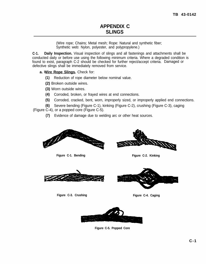
a. Wire Rope Slings. Check for:
(1) Reduction of rope diameter below nominal value.
(2) Broken outside wires.
(3) Worn outside wires.(4) Corroded, broken, or frayed wires at end connections.(5) Corroded, cracked, bent, worn, improperly sized, or improperly applied end connections.(6) Severe bending (Figure C-1), kinking (Figure C-2), crushing (Figure C-3), caging
(Figure C-4), or a popped core (Figure C-5).
(7) Evidence of damage due to welding arc or other heat sources.
Figure C-1. Bending Figure C-2. Kinking
Figure C-3. Crushing Figure C-4. Caging
Figure C-5. Popped Core
C-1

TB 43-0142
b. Chain Slings. Check for:
(1) Excessive wear or stretch.
(2) Bent or twisted links
(3) Defective welds.
(4) Nicks and gouges.
c. Metal Mesh Slings. Check for:
(1) Unpadded sharp comers.
(2) Evidence of twisting or kinking.
(3) A broken weld or brazed joint along the sling edge.
(4) A broken wire in any part of the mesh.
(5) Reduction in wire diameter.
(6) tack of flexibility due to distortion of the fabric.
(7) Distortion of handle.
(8) Evidence of heat damage.
d. Rope (Natural and Synthetic Fiber) Slings. The existence of any of the following conditionswill require that the sling be immediately removed from service:
(1) Abnormal wear.
(2) Powered fiber between strands.
(3) Broken or cut fibers.
(4) Variation in the size or roundness of strands.
(5) Discoloration or rotting.
(6) Distortion of hardware in the sling.
(7) Fiber rope slings shall not be used if end attachments which are in contact with the ropehave sharp edges or projections.
e. Synthetic Web Slings.
(1)web material.
Each sling shall be marked or coded to show the rated capacities and type of synthetic
(2) Synthetic webbing should be of uniform thickness and width and selvage edges shouldnot be split from webbings width.
(3) Fittings should be free of all sharp edges that could in any way damage the webbing.
(4)burns.
Sling surface should have no evidence of melting or charring from acid, caustic, or other
(5) In addition, check for the following:
(a) Snags, punctures, tears, or cuts.
(b) Broken or worn stitches.
(c) Distortion of fittings.
C - 2
TB 43-0142
f. Hoisting Beam Slings. This type sling is commonly used for removing engines or powerpacks from aircraft and combat vehicles. Inspect these slings for the following conditions:
(1) Proper assembly.
(2) Cracked or broken welds.
(3) Bent or loose bolts, rivets, pins and other attachment devices.
(4) Excessive wear or corrosion.
(5) Distortion of hoist attachment or terminal ring.
(6) Defects associated with wire rope, chain, metal mesh, or synthetic web components(refer to paragraphs C-1.a. through C-1.e. for specific inspection requirements.)
C-2. Periodic Inspections. A thorough periodic inspection of slings shall be made on a regularbasis, to be determined by frequency of sling use, severity of service conditions, nature of lifts beingmade, and experience gained on the service life of slings used in similar circumstances. Suchinspections shall in no event be at intervals greater than once every 12 months. Criteria in paragraphC-1, and the following should be used:
a. Wire Ropes Wire Rope Slings. Check for:
(I) Broken wires, Replace the wire rope when six randomly distributed broken wires in onerope lay, or three broken wires in one strand in one rope lay are found. Broken wire count should bemade of the worst strand at the worst section of the wire rope and confined to the distance requiredfor one strand to make one complete turn around the rope. Broken wire count wilt be entered on thetest record.
(2) Reduction In diameter. Marked reduction in diameter of wire rope may indicate loss ofcore support. Replacement should be made when reductions are more than:
1/64 inch for diameters up to and including 5/16 inch.1/32 inch for diameters 3/8 inch up to and including 1/2 inch.3/64 inch for diameters 9/16 inch up to and including 3/4 inch.1/16 inch for diameters 7/8 inch up to and including 1-1/8 inch.3/32 inch for diameters 1-1/4 inch up to and including 1-1/2 inch.
(3) Wear. Replace when wear of one-third the original diameter of outside individual wires isobserved.
(4) Condition of end attachments.
(a) Special attention should be given to end attachments. Ropes should be examinedfrequently at socketed fittings, and upon the development of one broken wire adjacent to this point,the rope should be r-e-socketed or replaced. Re-socketing should not be attempted if the resultingrope length will be insufficient for proper operation.
C - 3

TB 43-0142
Figure C-6. Slings(b) When eyes are formed using wire rope clips, the clips will be spaced six diameters of
the rope apart. The clips U-bolts will be installed on the dead end of the rope with the base againstthe live end; see Figure C-6. Nuts on U-bolts should be checked after initial use and re-tightened, ifnecessary, to the torque specifications in Table C-1. The number of clips and the proper torquenecessary to assemble wire rope eye-loop connections with a nominal efficiency of 80 percent is asfollows:
Table C-1. Wire Rope Clip Specifications*
Torque to beRope applied to Number Nominal size
diameter nuts to clips(inches)
of clips(ft-lbs)
of clips(inches)
5/16 25 3 3/8
3/8 25 3 3/8
7/16 40 4 1/2
1/2 40 4 1/2
5/8 65 4 5/83/4 100 4 3/4
7/8 165 5 1
1 165 5 1
1-1/4 250 5 1-1/4
1-3/8 375 6 1-1/2
1-1/2 375 6 1-1/2
1-3/4 560 6 1-3/4
l When using Crosby Rope Clips, caution should be used to ascertain that the saddle is ofthe proper rope lay, i.e., Right or Left, as a rope can be cut by using the wrong saddle.
C - 4
TB 43-0142
NOTE
To assemble a satisfactory end-to-end connection, the number of clipsindicated in the table above should be increased by two, with the torqueremaining unchanged. Replace thimbles which are distorted or excessivelyworn.
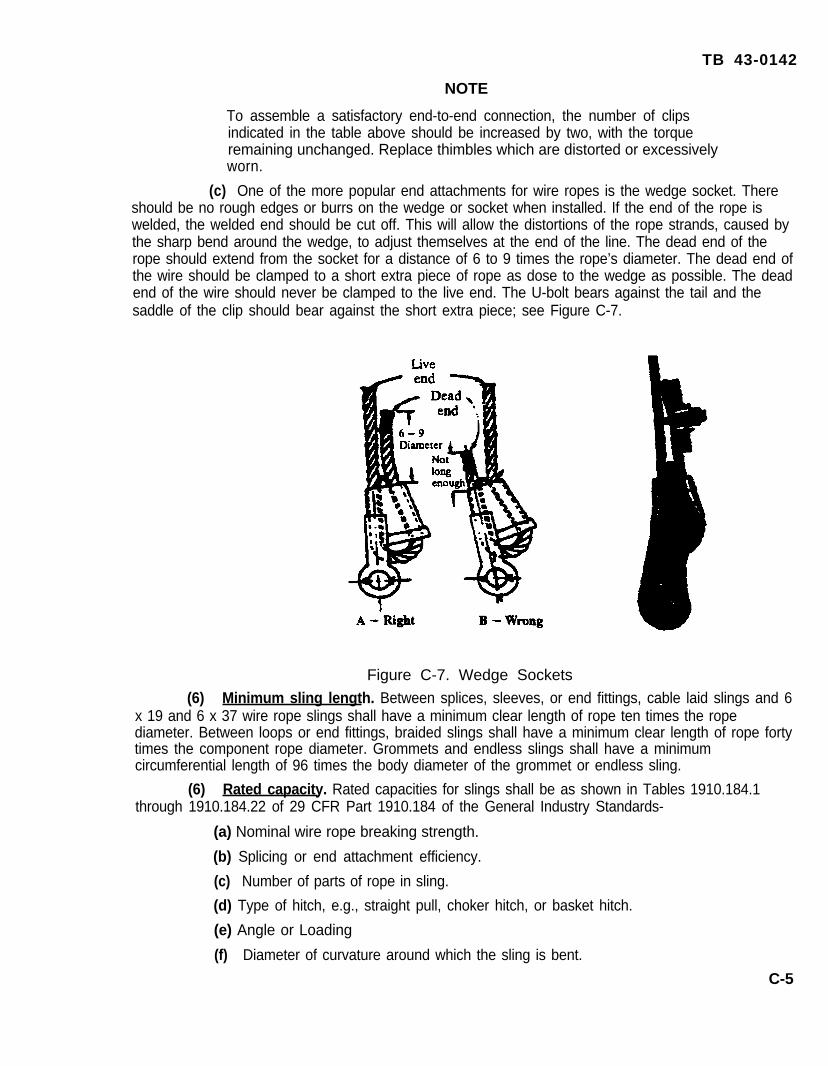
(c) One of the more popular end attachments for wire ropes is the wedge socket. Thereshould be no rough edges or burrs on the wedge or socket when installed. If the end of the rope iswelded, the welded end should be cut off. This will allow the distortions of the rope strands, caused bythe sharp bend around the wedge, to adjust themselves at the end of the line. The dead end of therope should extend from the socket for a distance of 6 to 9 times the rope’s diameter. The dead end ofthe wire should be clamped to a short extra piece of rope as dose to the wedge as possible. The deadend of the wire should never be clamped to the live end. The U-bolt bears against the tail and thesaddle of the clip should bear against the short extra piece; see Figure C-7.
Figure C-7. Wedge Sockets
(6) Minimum sling length. Between splices, sleeves, or end fittings, cable laid slings and 6x 19 and 6 x 37 wire rope slings shall have a minimum clear length of rope ten times the ropediameter. Between loops or end fittings, braided slings shall have a minimum clear length of rope fortytimes the component rope diameter. Grommets and endless slings shall have a minimumcircumferential length of 96 times the body diameter of the grommet or endless sling.
(6) Rated capacity. Rated capacities for slings shall be as shown in Tables 1910.184.1through 1910.184.22 of 29 CFR Part 1910.184 of the General Industry Standards-
(a) Nominal wire rope breaking strength.
(b) Splicing or end attachment efficiency.
(c) Number of parts of rope in sling.
(d) Type of hitch, e.g., straight pull, choker hitch, or basket hitch.
(e) Angle or Loading
(f) Diameter of curvature around which the sling is bent.
C-5

TB 43-0142
(7) Corrosion. Corrosion will often occur internally before there is any visible externalevidence on the rope surface. Pitting of wires is a cause for immediate rope removal. A slightdiscoloring of rust merely indicates a need for lubrication. By contrast, severe rusting is grounds forimmediate rope replacement.
(8) Kinks. Kinks are permanent distortions caused by loops drawn too tightly. Ropes withkinks must be removed from service.
(9) Basketing. In some cables with longer lays or smaller diameter wires, the outer layer ofwires or strands can loosen when bent with no load applied. In many instances the rope can be gentlyworked back and forth to resume its original configuration. If the rope does not resume its originalshape with a load heavy enough to straighten the rope, the rope must be replaced.
(10) Heat Damage. Extended exposure to a fire can result in loss of internal lubrication oreven a loss in strength of the rope. Obvious scorching is grounds for rope replacement.
(11) Protruding Core. If, for any cause, the rope core protrudes from an opening betweenthe strands, the rope is unfit for service and should be replaced.
(12) Electric Arc. Rope that has been in contact with a live power line or lightening may havewires that are fused, discolored, and/or annealed; any of the preceding is justification for ropereplacement.
b. Allow Steel Chain Slings.
(1) All chains shall be manufactured and tested by the chain manufacturer in accordancewith ASTM Specification for Alloy Steel Chain A391 -65 (ANSI G61 .1-1966). Other grades of prooftested steel chain include Proof Coil, BBB Coil, and Hi-Test Chain. These grades are notrecommended for overhead lifting and therefore are not covered by this bulletin.
(2) Hooks, rings, oblong links, pear shaped links, welded or mechanical coupling links, andother attachments shall have a rated capacity at least equal to that of the alloy steel chain with whichthey are used. Homemade links, makeshift fasteners formed from bolts, rods, etc., and other suchattachments shall not be used. Mechanical coupling links or low carbon steel repair links shall not beused to repair broken lengths of chain.
(3) Inspection shall be made on a link by link basis with the chain collapsed. If any link doesnot hinge freely with the adjoining link, or if obvious signs of stretch are detected, the assembly shallbe removed from service. If wear at any point of any chain link exceeds that shown in Table C-2, theassembly shall be removed from service. Sharp transverse nicks should be rounded out by grinding. Ifthe depth of the gouge or rounded out portion exceeds the values shown in Table C-2, the assemblyshall be removed from service.
(4) When new, chains should be calibrated for length in sections of from 1 to 3 feet long(section should have a minimum of 5 links). At each inspection, the increase in length of the chainsection shall be measured and entered into the maintenance records; refer to paragraph 6e(s).Reduce the rated capacity by 2 percent for each I percent increase in length. Hoist chains shall beremoved from service when a 5 percent increase in length occurs and sling chains shall be removedfrom service when a 10 percent increase in length occurs.
C - 6

Table C-2. Load Testing Parameters.
Chain Sizes(Inches)
1/4 3/64
3/8 5/64
1/2 7/64
5/8 9/64
3/4 5/32
7/8 11/64
1 3/64
1-1/6 7/321-1/4 1/4
1-3/8 9/32
1-1/2 5/16
1-3/4 11/32
TB 43-0142
Maximum Allowable Wear(Inches)
c. Metal Mesh Slings.
(1) All slings shall have permanently affixed durable identification showing the rated capacityof vertical basket hitch and choker hitch slings and the next periodic inspection date.
(2) Reduction in wire diameter of 25 percent due to abrasion or 15 percent due to corrosion.
(3) Distortion of the female handle so that the depth of the slot is increased more than 10percent; see Figure C-8.
(4) Distortion of either handle so that the width of the eye is decreased more than 10percent; see Figure C-8.
(5) A 15 percent reduction of the original cross sectional area of metal at any point aroundthe handle of the eye; see Figure C-8.
C - 7

TB 43-0142
1Definitions of peculiar terms can be found in either ANSI 630.9-1971or the General Industrial Standards 29 GFR Part 1910.184.
2These tables are taken from ANSI Standard 830.9-1971, "Slings”.
Figure C-8. Metal Mesh Sling Showing Characteristic Parts.
d. Rope. Natural and Synthetic Fiber Slings. Fiber rope slings made from conventional threestrand construction fiber rope shall not be used with loads in excess of the rated capacities prescribedin Tables 16 through 19 of the General Industry Standards 29 CFR Part 1910.184.
e. Synthetic Web Slings. Synthetic web slings should not be used with loads in excess of ratedcapacities prescribed in Tables 20 through 22 of the General Industry Standards 29 CFR Part1910.184. Types of slings and types of hitches, etc., are illustrated in the General Industry Standardsand ANSI Standard 830.9.
f. Hoisting Beam Slings. Refer to inspection criteria in paragraph C-1.f. In addition, refer toparagraphs C-2.a. through C-2.e. for inspection criteria associated with wire rope, chain, metal mesh,or synthetic web components.
C-3. Tests. Conduct the function testing of slings and cables concurrently with the correspondinginspection and test of the lifting device system of which they are integral part. Working load limits ofthe lifting ropes, chains, slings, or combinations should never be less than the load rating of thehoisting device. Keep individual records for each sling. Record pretest and post-test findings, actionstaken, and test date in the historical records of the sling or lifting cable.
C-4. Hooks. Hooks used with slings shall be inspected concurrently with the slings. Check fordeformation, distortion, cracks, wear, damage, or malfunctioning latch and hook attachment. Visualexamination may be supplemented with magnetic particle or other non destructive type testingwhenever apparent conditions indicate the need for more in-depth inspection. Hooks shall beremoved from service if they are cracked, have throat openings of more than fifteen percent in excessof normal, more than a ten degree bend or twist from the plane of the unbent hook, or wear exceedingten percent of tne original dimensions.
C - 8

TB 43-0142
APPENDIX DTRUCKS, FORKLIFT
D-1. Daily Inspection.
a. Check for proper marking
b. Check for evidence of mishandling or damage.
c. Perform normal daily preoperational preventive maintenance inspections and checks asprescribed in applicable technical manuals for the equipment.
d. Carefully inspect all safety devices including specialized features of forklift trucks approved forhandling explosives end ammunition.
D-2. Periodic Inspection. Complete inspection of forklift trucks shall be performed at theintervals defined in paragraph 4. Criteria in paragraph D-1, requirements of any applicable technicalmanual, and the following should be used.
a. Check all mechanical controls for proper adjustments and check the entire control mechanismfor excessive wear of components and contamination by leaking lubricants or foreign matter.
b. Check hydraulic system seals, hoses, lines, fittings, pumps, and valves for deterioration,leaks, and wear.
c. Check the mast and lift carriage assembly, including forks and chains, for cracks, brokenwelds, distortion, improper fit, and excessive wear.
d. Check the brake and steering systems for excessively worn or defective moving parts toinclude seat switches, parking brakes, and brake interlock switches.
e. Check electrical, gasoline, and diesel systems for signs of malfunction, excessivedeterioration, dirt or moisture accumulation, and compliance with applicable safety regulations.
f. Check protective motor control circuit devices, battery cable connectors, battery compartmentinsulation, thermo protectors, compartment covers, filters, and emergency switches. Insure that typeEE (Electrical equipment enclosed to prevent emission of sparks in potentially hazardousatmospheres) electric trucks have static electricity discharge straps properly installed, immediatelyadjacent to the drive wheels, to effect contact with road or floor surfaces, when such trucks are usedin areas where an explosive dust potential exists. Specification MIL-T-21 969 (refer to latest revision)provides procedures for testing the discharge straps and requires a resistance between chassis andfloor, through the straps, of no more than 250,000 ohms.
(1) Ensure that all electrical cables are appropriately mounted and protected to preventdamage by abrasion, cutting, or catching on stationary objects.
(2) Ensure that batteries are securely fastened in place to prevent spillage of electrolyte ontoelectrical cables.
(3) Ensure that battery compartments provide ample ventilation and have openings properlyguarded to prevent contact of foreign objects with cell terminals.
(4) Equipment must be clean and free of excessive oil and grease accumulations,particularly within the confines of the motors and on electrical contacts.
g. All deficiencies observed shall be corrected and repairs made prior to testing.D-1
TB 43-0142
D-3. Tests. When required by paragraph 4a, perform a functional test to determine operability ofthe equipment. Functional tasting shall consist of lifting a characteristic load (determined locally),holding it at an appropriate height for one minute, maneuvering it in a manner which will simulate theoperation of the fifting device in the working environment, and lowering it to its original position. Forlifting devices used to handle hazardous materials, conduct the function teat as above, using an inertitem equal in weight to or heavier than (not to exceed the manufacturers load rating of the device) theheaviest item normally lifted by the devices as its characteristic load. A visual inspection will beperformed prior to and after functional test is performed. Record pretest and post-test findings,actions taken, and test date in the end item’s historical records.
D - 2
TB 43-0142
APPENDIX EJACKS AND STANDS
E-1. Daily Inspection. The following items shall be inspected daily or before use:
a. Check for proper marking, i.e., rated load (sustaining and lifting, if appropriate).
b. Check for cleanliness and proper lubrication.
c. Check for broken, cracked or distorted mechanical parts or housings, loose bolts or rivets, andother evidence of mishandling.
d. Check for hydraulic leaks; worn, bent, or damaged screw threads; cracked or broken rackteeth; scored or damaged ram; improperly functioning swivel heads and caps; improper engagementor extreme wear of pawl and rack, as appropriate to type of jack.
e. Check that handle is free from grease and oil.
f. Other items as specified in technical manuals or manufacturer’s instructions, which may affectoperation.
E-2. Periodic Inspection. Complete inspection of jacks and stands shall be performed every 6months. Periodic inspections shall include the items of E-1 above, requirements of any applicabletechnical manual, manufacturers recommendations, and the following:
a. Check for corrosion of metal parts.
b. Jack should be disassembled for cleaning and examination for internal wear or damage ifexternal appearance indicates there may be internal difficulty.
E-3. Tests. When required by paragraph 4a, perform a functional test to determine operability ofthe equipment. Functional testing shall consist of lifting a characteristic load (determined locally),holding it at an appropriate height for one minute, maneuvering it in a manner which will simulate theoperation of the lifting device in the working environment, and lowering it to its original position. Forlifting devices used to handle hazardous materials, conduct the function test as above, using an inertitem equal in weight to or heavier than (not to exceed the manufacturers load rating of the device) theheaviest item normally lifted by the devices as its characteristic load. A visual inspection will beperformed prior to and after functional test is performed. Record pretest and post-test findings,actions taken, and test date in the end item’s historical records.
E-1/(E-2 blank)
TB 43-0142
By Order of the Secretary of the Army:
DENNIS J. REIMERGeneral, United States Army
Chief of Staff
Administrative Assistant to theSecretary of the Army
03086
DISTRIBUTION:To be distributed in accordance with DA Form 12-34-E, block no. 0515, requirements
for TB 43-0142.
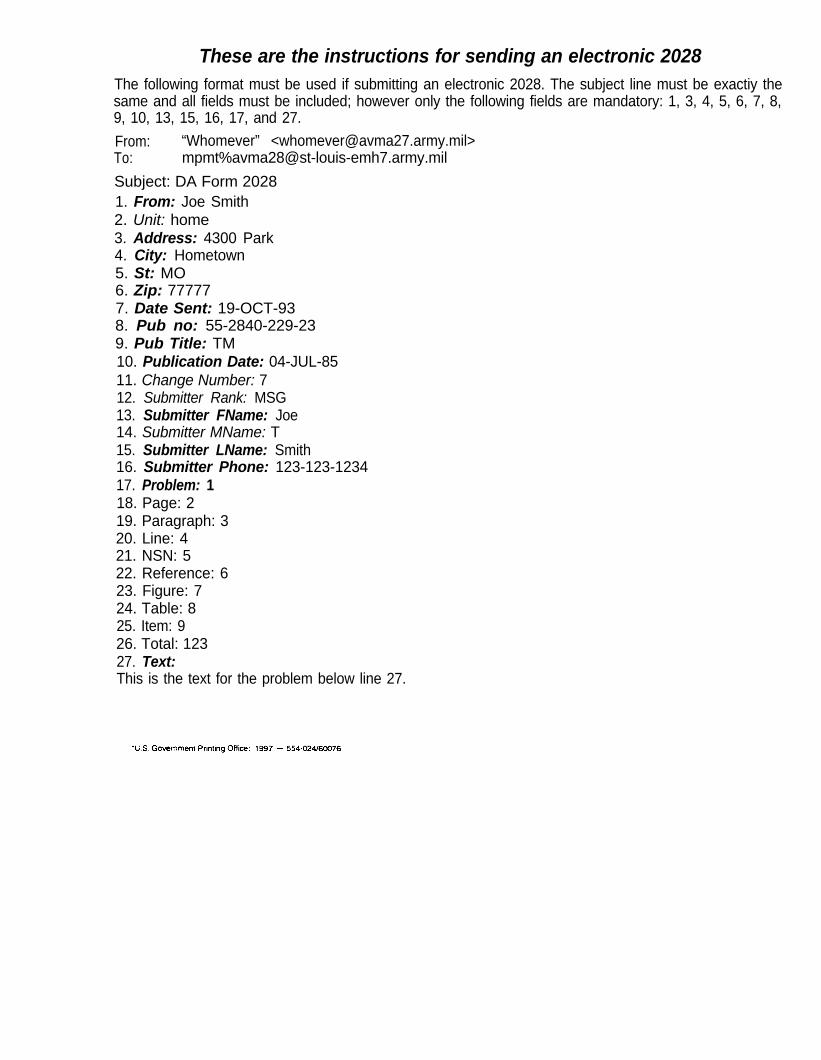
These are the instructions for sending an electronic 2028The following format must be used if submitting an electronic 2028. The subject line must be exactiy thesame and all fields must be included; however only the following fields are mandatory: 1, 3, 4, 5, 6, 7, 8,9, 10, 13, 15, 16, 17, and 27.
From: “Whomever” <[email protected]>To: mpmt%[email protected]
Subject: DA Form 20281. From: Joe Smith2. Unit: home3. Address: 4300 Park4. City: Hometown5. St: MO6. Zip: 777777. Date Sent: 19-OCT-938. Pub no: 55-2840-229-239. Pub Title: TM10. Publication Date: 04-JUL-8511. Change Number: 712. Submitter Rank: MSG13. Submitter FName: Joe14. Submitter MName: T15. Submitter LName: Smith16. Submitter Phone: 123-123-123417. Problem: 118. Page: 219. Paragraph: 320. Line: 421. NSN: 522. Reference: 623. Figure: 724. Table: 825. Item: 926. Total: 12327. Text:This is the text for the problem below line 27.


PIN: 020130-000