safety instructions - go to instructions i ... all values of parameters is set to values of factory...
TRANSCRIPT


Safety Instructions
i
Safety Instructions
To prevent injury and property damage, follow these instruc-tions. Incorrect operation due to ignoring instructions will cause harm or damage.
The seriousness of which is indicated by the following symbols.
Symbol Meaning
Warning This symbol indicates the possibility of death or serious injury.
Caution This symbol indicates the possibility of injury or damage to property.
RemarkRemarkRemarkRemark
Even if the instructions are indicated as ‘Caution’, it can cause a serious result according to the kind of operation and the environ-ment.
The meaning of each symbol in this manual and on your equipment is as follows.
Symbol Meaning
This is the safety alert symbol.
Read and follow instructions carefully to avoid dangerous situation.
This symbol alerts the user to the presence of “dangerous voltage” inside the product that might cause harm or electric shock.
After reading this manual, keep it in the place that the user al-ways can contact easily.
This manual should be given to the person who actually uses the products and is responsible for their maintenance.
WARNINGWARNINGWARNINGWARNING
Do not remove the cover while power is applied or t he unit is in operation.
Otherwise, electric shock could occur.

Safety Instructions
ii
WARNINGWARNINGWARNINGWARNING
Do not run the inverter with the front cover remove d.
Otherwise, you may get an electric shock due to high voltage termi-nals or charged capacitor exposure.
Do not remove the cover except for periodic inspect ions or wir-ing, even if the input power is not applied.
Otherwise, you may access the charged circuits and get an electric shock.
Wiring and periodic inspections should be performed at least 10 minutes after disconnecting the input power and after checking the DC link voltage is discharged with a m eter (below DC 30V).
Otherwise, you may get an electric shock.
Operate the switches with dry hands.
Otherwise, you may get an electric shock.
Do not use the cable when its insulating tube is da maged.
Otherwise, you may get an electric shock.
Do not subject the cables to scratches, excessive s tress, heavy loads or pinching.
Otherwise, you may get an electric shock.
CAUTIONCAUTIONCAUTIONCAUTION
Install the inverter on a non-flammable surface. Do not place flammable material nearby.
Otherwise, fire could occur.
Disconnect immediately the input power if the inver ter gets damaged.
Otherwise, it could result in a secondary accident and fire.
After the input power is applied or removed, the in verter will remain hot for a couple of minutes.
Otherwise, you may get bodily injuries such as skin-burn or dam-age.
Do not apply power to a damaged inverter or to an i nverter with parts missing even if the installation is complete.
Otherwise, electric shock could occur.
Do not allow lint, paper, wood chips, dust, metalli c chips or other foreign matter into the drive.
Otherwise, fire or accident could occur.

Safety Instructions
iii
Caution for Use
Transportation and Installation
Be sure to carry inverter in a proper way suitable for its weight, or it may result in damage to inverter.
Be sure to use heat-treated wooden crate when you adopt wooden packaging for the product.
Do not pile up inverters above allowable limit.
Be sure to install the inverter as directed in this instruction manual.
Do not turn off the power supply to the damaged inverter.
Do not open the front cover while carrying the inverter.
Do not place the heavy material on the inverter.
The direction of installation should be observed properly as criterions specified in this manual show.
Make sure that you should not put screw, metal material, water, oil and the inflammable something else.
Keep in mind that inverter is very vulnerable to drop from the mid air and strong shock.
Don't let the inverter exposed to rain, snow, fog, dust, etc.
Do not cover, nor block, the ventilating system having cooling fan. It may cause the inverter overheated.
Be sure to check the power is off when installing the inverter.
To prevent the risk of fire or electric shock, keep the connected wire in a sound condition. Use the wire that meets the standard in a recom-mended length.
Be sure to ground the inverter. (Under 10 Ω to 200V class, Under 100 Ω to 400V class)
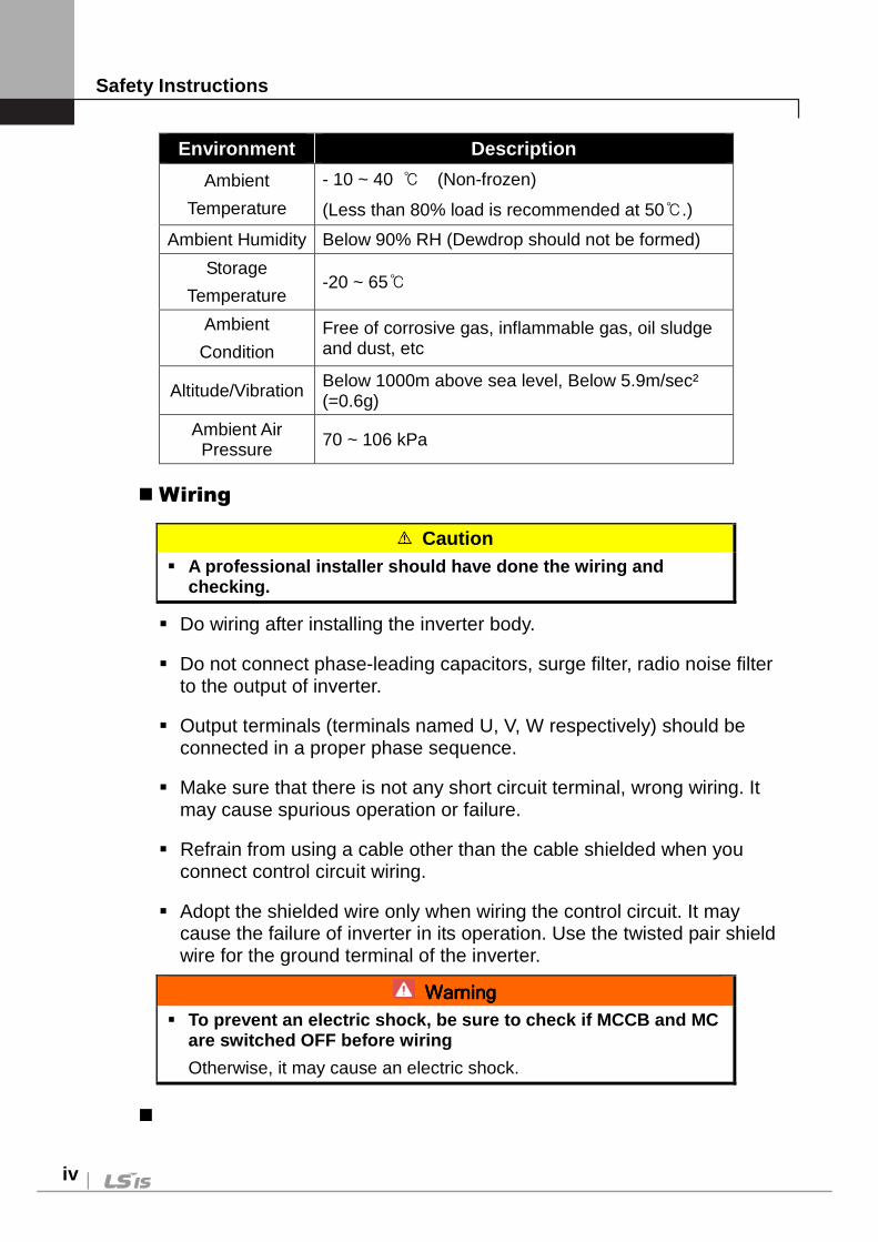
Be certain to use the inverter under the following conditions.
Safety Instructions
iv
Environment Description
Ambient
Temperature
- 10 ~ 40 (Non-frozen)
(Less than 80% load is recommended at 50.)
Ambient Humidity Below 90% RH (Dewdrop should not be formed)
Storage
Temperature -20 ~ 65
Ambient
Condition Free of corrosive gas, inflammable gas, oil sludge and dust, etc
Altitude/Vibration Below 1000m above sea level, Below 5.9m/sec² (=0.6g)
Ambient Air Pressure 70 ~ 106 kPa
Wiring
Caution A professional installer should have done the wirin g and
checking.
Do wiring after installing the inverter body.
Do not connect phase-leading capacitors, surge filter, radio noise filter to the output of inverter.
Output terminals (terminals named U, V, W respectively) should be connected in a proper phase sequence.
Make sure that there is not any short circuit terminal, wrong wiring. It may cause spurious operation or failure.
Refrain from using a cable other than the cable shielded when you connect control circuit wiring.
Adopt the shielded wire only when wiring the control circuit. It may cause the failure of inverter in its operation. Use the twisted pair shield wire for the ground terminal of the inverter.
WarningWarningWarningWarning
To prevent an electric shock, be sure to check if M CCB and MC are switched OFF before wiring
Otherwise, it may cause an electric shock.

Safety Instructions
v
Adjustment before starting trial operation
Do not supply the excessive range of voltage displayed in the user manual to the each terminal. It may cause damage to the inverter.
Current hunting can be occurred in the low speed territory during test-ing. It occurs where the capacity is above 110kW with no-load and the axis is not connected. The current hunting has a gap according to the motor characteristic. It will be disappeared when the load is connected and it is not the indica-tion of abnormal condition. If the hunting is occurred seriously, please stop the testing and oper-ates with the load.
Be sure to check relevant parameters for the application before start-ing trial operation.
How to Use
Be sure not to approach the machine when retry function is selected. The machine may start working suddenly.
Stop key on the keypad should be set to be in use. For safety, addi-tional emergency stop circuit should be required.
Inverter restarts if alarm condition is cleared while FX/RX signal is on. Therefore, be sure to operate the alarm reset switch after checking if FX / RX signal is off.
Never modify the inverter for inappropriate use.
When a magnetic contactor is installed on the power source, do not frequently start or stop using this magnetic contactor. It may cause the failure of inverter.
Noise filter should be used for the minimization of troubles by electro-magnetic noise. Electronic equipments close to the inverter should be protected against the damage caused by troubles.
Be sure to install the AC reactor at the input of inverter in case of input voltage unbalance. Otherwise, generator or phase-leading capacitors may be destroyed by the harmonic current from inverter.
If 400V class motor is used with the inverter, insulation-enforced motor should be used or countermeasures against the suppression of micro-surge voltage generated by the inverter should be carried out.

Safety Instructions
vi
Otherwise, micro-surge voltage is generated across input terminal for the motor and this voltage lowers allowable insulation break-down voltage and then, may cause the destruction of the motor.
Be sure to set the parameters once more, in case of initialization of pa-rameters, all values of parameters is set to values of factory setting.
High speed operation can be set easily, therefore be sure to check the performance of motor or machine before changing parameter value.
DC braking function cannot produce a zero-servo torque. If required, additional equipment should be installed.
When inverter trip or emergency stop (BX) occurs without keypad con-nected, LED on the control board will blink by the interval of 0.5 sec. But LED will blink by 1 sec when keypad is connected. This function displays which trip will be occurred according to the connection of key-pad.
Do not change wiring, nor disconnect connector or option card during the operation of inverter.
Do not disconnect the motor wiring while the voltage of inverter is out-put. Mishandling may cause damage to the inverter.
Be sure to handle the inverter and option care in the order recom-mended in the Electro Static Discharge (ESD) Countermeasure. Mis-handling may lead to damage to the circuit on the PCB caused by ESD.
Countermeasure against malfunction troubles
If inverter is damaged and then gets into uncontrollable situation, the machine may lead to the dangerous situation, therefore to avoid this situation, be sure to install the additional equipments such as brake.
Maintenance, inspection and parts replacement
Do not perform the megger (insulation resistance check) test on the control board.
Please refer to intervals for parts replacement on Chapter 8.
Disposal
Handle the inverter as an industrial waste when disposing of it.

Safety Instructions
vii
Our inverter contains the raw material of value that can be recycled from the aspect of energy and resource preservation. All the package materials and metal parts are recyclable. Plastics are also recyclable, but may be burnt under the controllable environment depending on the local regulation.
General Instruction
The drawing in this user manual is represented the details of the inner inverter, so, the drawing is described without cover part and circuit breaker. But, cover and circuit breaker should be mounted before the operation following to the instruction of user manual.
Turn off the power of inverter when the inverter is not used.
Cleaning
Be sure to operate the inverter under a clean condition.
When cleaning the inverter, be sure to check the inverter is off. Start cleaning it with all the plugs connected with the inverter socket re-moved.
Never clean the inverter using wet cloth or water. Wipe the stained ar-ea softly using the cloth completely wet with a neutral detergent or ethanol.
Never use the solution such as acetone, benzene, toluene, alcohol, etc. They may cause the coating on the surface of the inverter to peel off. In addition, do not clean LCD display, etc. using detergent or alcohol.
Storage
Be sure to keep the inverter under the following conditions if you don't use it for a long period of time.
Make sure that you satisfy the recommended storage environment. (See page v.)
If the storage period exceeds 3 months, be sure to keep it at the ambi-ent temperature of -10 ~ +30˚ C to prevent『Deterioration by Temper-ature』of electrolytic condenser.
Safety Instructions
viii
Be sure to keep it in a proper package to prevent moisture, etc. Put the desiccant (Silica Gel), etc., in the package so that the relative humidity in the package can be maintained at 70% or less.
When it is exposed to moisture or dust (mounted on the『System』 or 『Control Panel』, etc. installed at the construction site), remove it and then keep it under the environmental condition specified in the page v.
CautionCautionCautionCaution
If the inverter has been left long with electric cu rrent not charged, the nature of electrolytic condenser can b e deterio-rated. So be sure to have it plugged in for 30 ~ 60 minutes once a year. Do not perform wiring and operation of the output side (secondary side).

This User's Manual is aimed at……
This User's Manual is aimed at……
Describing specification, installation, operation, function, and maintenance of SV-iV5 series inverter provided for the users who are familiar with and having basic experience in the invert-er.
Be sure to understand function, performance, installation, and operation of the product by reading through this User's Manual completely prior to your use of SV-iV5 series inverter that you have purchased. In addition, you are required to have this Us-er's Manual properly delivered to the end-user and mainte-nance manager.
Option Module Guide
The following Option Module Guides will be provided when you purchase the applicable Option Module. In addition, if you access our homepage http://www.lsis.com/ [Customer Support] - [Down-load Data Room], you can download it in PDF file.
IV5 EL (Elevator) I/O Option Module Guide (Korean)
IV5 SYNC Option Module Guide (Korean)
IV5 SIN/COS Encoder Card Option Module Guide (Korean)
IP5A/IV5 RS-485 & Modbus-RTU Option Module Guide (Korean)
IS5/IP5A/IV5 Profibus-DP Card Option Module Guide (Korean)
IS5/IP5A/IV5 DeviceNet Card Option Module Guide (Korean)
IP5A/IV5 CC-Link Card Option Module Guide (Korean)

Table of Contents
x
Chapter 1 Introduction
1.1 Key Features ----------------------------------------------------------- 1-1
1.2 Inverter Nameplate and Model ------------------------------------- 1-2
Chapter 2 Specification
2.1 Standard Specification ----------------------------------------------- 2-1
2.2 Common Specification ----------------------------------------------- 2-3
Chapter 3 Installation and Wiring
3.1. Caution on Installation ----------------------------------------------- 3-2
3.2 Basic Wiring ------------------------------------------------------------ 3-4
3.3 Power Circuit Terminal ----------------------------------------------- 3-11
3.4 Control Board and Terminal ----------------------------------------- 3-18
3.5 Terminal of the Auxiliary Power Supply -------------------------- 3-27
Chapter 4 Trial Operation
4.1 Keypad Operation ----------------------------------------------------- 4-1
4.2 Keypad LCD Display-------------------------------------------------- 4-2
4.3 Setting of Parameter Values ---------------------------------------- 4-3
4.4 Data Group -------------------------------------------------------------- 4-4
4.5 Auto-Tuning ------------------------------------------------------------- 4-6
4.6 Pulse Encoder Check ------------------------------------------------ 4-10
4.7 Operation by Keypad ------------------------------------------------- 4-11
4.8 Operation by Control Terminal ------------------------------------- 4-12
Chapter 5 Function Code Table
5.1 Display Group (DIS_[][]) --------------------------------------------- 5-1
5.2 Digital DIO Group (DIO_[][]) ---------------------------------------- 5-3
5.3 Parameter Group (PAR_[][]) ---------------------------------------- 5-7
5.4 Function Group (FUN_[][]) ------------------------------------------ 5-9
5.5 Control Group (CON_[][]) -------------------------------------------- 5-13
5.6 User Group (USR_[][]) ----------------------------------------------- 5-15
5.7 Second motor Group (2nd_[][]) ------------------------------------ 5-16
5.8 Option Group (EXT_[][]) --------------------------------------------- 5-17
5.9 Analog AIO Group (AIO_[][]) ---------------------------------------- 5-19

Table of Contents
xi
5.10 Sensorless control Group (SLS_[][]) --------------------------- 5-24
Chapter 6 Inspection and Replacement
6.1 Precautions ------------------------------------------------------------- 6-1
6.2 Checking Points ------------------------------------------------------- 6-1
6.3 Routine Checking ----------------------------------------------------- 6-2
6.4 Regular Checking (1 year interval) ------------------------------- 6-4
6.5 Meggar Test ------------------------------------------------------------ 6-6
6.6 Regular Checking (2 year interval) ------------------------------- 6-7
6.7 Replacement Interval and Maintenance of the Key
Components -----------------------------------------------------------------
6-7
6.8 How to Check at Diode Module & IGBT Inspection ----------- 6-8
Chapter 7 Troubleshooting and Maintenance
7.1 Fault Display ------------------------------------------------------------ 7-1
7.2 Monitoring Fault Condition ------------------------------------------ 7-4
7.3 Fault Reset -------------------------------------------------------------- 7-4
7.4 Fault Remedy ---------------------------------------------------------- 7-4
Chapter 8 Accessories
8.1 MCCB(LS), ELB(LS), Magnetic contactor(LS), Input/Output
Wire Specifications ----------------------------------------------------
8-1
8.2 AC input fuse, AC reactor, DC reactor --------------------------- 8-2
8.3 The selection of Braking Resistor and the Unit ---------------- 8-3
Chapter 9 Dimensions ----------------------------------------------------------------- 9-1

1. Introduction
1-1
Chapter 1 - Introduction
1.1 Key Features Current Controlled Vector Control Inverter with Speed Sensor using IGBT as
Power Semiconductor Device. Tension/Torque Control and Wide Variety of Process Control Process PI Control, Draw Control, Droop Control, Synchronous Control, WEB
Control etc. Auto-tuning of Motor Parameters for Precise Speed/Torque Control :
Rotational/Standstill mode Encoder error (H/W and S/W) detection function Auxiliary battery function and Emgergent operation by battery operation Various option for communication and application Inverter Application
Application Applicable Machine/System Features
Process Control
Steel Strip Paper Mill Textile Film Coater Printing Machine
Tension Control Wide Range of Speed Control
Hoisting Control
Lifts (Elevators) Parking Stacker Crane Crane Hoist
High Speed Operation High Starting Torque Positioning Wide Range of Speed Control
Machine Control Machine Tool Wire Drawing Extruder
High Speed Operation High Starting Torque Positioning
Others Conveyor Industrial Washing Machine
High Speed Operation Positioning
This instruction manual is designed for LS STARVERT -iV5 series Vector Control Inverters , which have excellent characteristics in speed and torque control with pulse encoder mounted on the shaft of 3 phase induction motor, and covers installation, maintenance, wiring and operation for these inverters.

1. Introduction
1-2
1.2 Inverter Nameplate and Model 1.2.1 Inverter nameplate (Example)
1.2.2 Inverter model name SV [][][][] iV5 – 2 DB (MD) (380V) (ENC) LS STARVERT Series
Max. Applicable Motor
022 : 2.2kW ~ 5000 : 500kW
iV5 Series
Input Voltage
2 : 200V Class (200 ~ 230V) ,
4 : 400V Class (380 ~ 480V)
Built-in DB Circuit
DB : Built-in DB Circuit (DB Resistors Integrated)
DC : DC Power Input
Blank : No Built-in DB Circuit (Use external DB Uni t)
MD : Mold Type (2.2~22kW)
(Electrical specification of MD type is based on specifications of 5.5~2.2kW except for the specification
of exterior and its size.)
Input Voltage
(380V) : 380V Input Voltage – 30~220kW(400V)
Blank : Below 22kW (200V/400V) and 280~500kW(400V)
ENCODER TYPE
-
-
-
-
-
-
-
- Blank : 5V Line Drive, 15V Open Collector
- 24V ENC : 24V Line Drive/Open Collector
Inverter Model Name
Input Power Source Specifications Rated Capacity Output Power Source Specifications Running Freq. / Rated Output Current
Bar Code
Serial Code
Output Capacity
SV [][][][]iV5-2DB
INPUT 200 - 230 V 3 Phase [][][]A 50/60Hz
OUTPUT 0 - Input V 3 Phase [][][]A 0 – 3600rpm
[][][]HP / [][][]kW
[][][][][][][][][][][]
LSIS Co.,Ltd

2. Specification
2-1
Chapter 2 - Specification 2.1 Standard Specification 2.1.1 200V Class (AC power input type)
SV[][][]iV5-2(DB) 022 037 055 075 110 150 185 220 300 370
Max. applicable motor output Note1)
[HP] 3 5 7.5 10 15 20 25 30 40 50
[kW] 2.2 3.7 5.5 7.5 11 15 18.5 22 30 37
Out
put
Capacity [kVA] Note2) 4.5 6.1 9.1 12.2 17.5 22.5 28.2 33.1 46 55
Rated current [A] 12 16 24 32 46 59 74 88 122 146
Speed 0 ~ 3600 (rpm)
Voltage 0 ~ 200V (230V Note3))
Inpu
t Voltage 3φ 200 ~ 230V (-10% ~ +10%)
Frequency 50 ~ 60Hz (±5%)
Inverter weight [kg(lbs)]
6 (13)
6 (13)
14 (30)
14 (30)
27.5 (60)
27.5 (60)
28 (61)
28 (61)
42 (93)
42 (93)
2.1.2 400V Class (AC power input type)
SV[][][]iV5-4(DB) 022 037 055 075 110 150 185 220 300 370 450
Max. applicable motor output (Note1)
[HP] 3 5 7.5 10 15 20 25 30 40 50 60
[kW] 2.2 3.7 5.5 7.5 11 15 18.5 22 30 37 45
Out
put
Capacity [kVA] Note2) 4.5 6.1 9.1 12.2 18.3 22.9 29.7 34.3 46 57 70
Rated current [A] 6 8 12 16 24 30 39 45 61 75 91
Speed 0 ~ 3600 (rpm)
Voltage 0 ~ 380V (480 Note3))
Inverter weight [kg(lbs)]
6 (13)
6 (13)
14 (30)
14 (30)
27 (59)
28 (61)
28 (61)
28 (61)
42 (93)
42 (93)
63 (139)
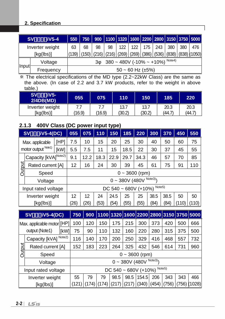
SV[][][][]iV5-4 550 750 900 1100 1320 1600 2200 2800 3150 3750 5000
Max. applicable motor output Note1)
[HP] 75 100 120 150 175 215 300 373 420 500 666
[kW] 55 75 90 110 132 160 220 280 315 375 500
Out
put
Capacity [kVA] Note2) 85 116 140 170 200 250 329 416 468 557 732
Rated Current [A] 110 152 183 223 264 325 432 546 614 731 960
Speed 0 ~ 3600 (rpm)
Voltage 0 ~ 380V (480V Note3))
2. Specification
2-2
SV[][][][]iV5-4 550 750 900 1100 1320 1600 2200 2800 3150 3750 5000
Inverter weight [kg(lbs)]
63 (139)
68 (150)
98 (216)
98 (216)
122 (269)
122 (269)
175 (386)
243 (536)
380 (838)
380 (838)
476 (1050)
Input Voltage 3φ 380 ~ 480V (-10% ~ +10%) Note4)
Frequency 50 ~ 60 Hz (±5%) ※ The electrical specifications of the MD type (2.2~22kW Class) are the same as
the above. (In case of 2.2 and 3.7 kW products, refer to the weight in above table.)
SV[][][]iV5-2/4DB(MD) 055 075 110 150 185 220
Inverter weight [kg(lbs)]
7.7 (16.9)
7.7 (16.9)
13.7 (30.2)
13.7 (30.2)
20.3 (44.7)
20.3 (44.7)
2.1.3 400V Class (DC power input type)
SV[][][]iV5-4(DC) 055 075 110 150 185 220 300 370 450 550
Max. applicable motor output Note1)
[HP] 7.5 10 15 20 25 30 40 50 60 75
[kW] 5.5 7.5 11 15 18.5 22 30 37 45 55
Out
put
Capacity [kVA]Note2) 9.1 12.2 18.3 22.9 29.7 34.3 46 57 70 85
Rated current [A] 12 16 24 30 39 45 61 75 91 110
Speed 0 ~ 3600 (rpm)
Voltage 0 ~ 380V (480V Note3))
Input rated voltage DC 540 ~ 680V (+10%) Note5)
Inverter weight [kg(lbs)]
12 (26)
12 (26)
24 (53)
24.5 (54)
25 (55)
25 (55)
38.5 (84)
38.5 (84)
50 (110)
50 (110)
SV[][][]iV5-4(DC) 750 900 1100 1320 1600 2200 2800 3150 3750 5000
Max. applicable motor output (Note1)
[HP] 100 120 150 175 215 300 373 420 500 666
[kW] 75 90 110 132 160 220 280 315 375 500
Out
put
Capacity [kVA] Note2) 116 140 170 200 250 329 416 468 557 732
Rated current [A] 152 183 223 264 325 432 546 614 731 960
Speed 0 ~ 3600 (rpm)
Voltage 0 ~ 380V (480V Note3))
Input rated voltage DC 540 ~ 680V (+10%) Note5)
Inverter weight [kg(lbs)]
55 (121)
79 (174)
79 (174)
98.5 (217)
98.5 (217)
154.5 (340)
206 (454)
343 (756)
343 (756)
466 (1028)

2. Specification
2-3
Note) 1. It represents the output capacity of maximum applicable motor in case 4-pole
motor is used. (220V is based on 220V and 400V is based on 440V.) 2. Rated capacity (=√3*V*I) is calculated based on 220V for 200V class, 440V for
400V class. 3. Maximum output voltage cannot be generated above specified input voltage. 4. Derate the rated current by 10% when the input voltage is in the range above
480V. 5. Rated current is derated by 10% above 680VDC of input voltage. ※ 500kW AC/DC input type products will be released soon.
2.2 Common Specification Items Detailed Specification
Inverter type Voltage source inverter using IGBT
Con
trol
Control method Vector control inverter with speed sensor attached, Sensorless Vector control inverter
Speed control accuracy
Analog setting: ± 0.01% (25 ± 10) of max. Speed (1,800 rpm)
Digital setting: ± 0.01% (0 ~ 40) of max. Speed (1,800 rpm)
Speed setting resolution
Analog setting: ± 0.1% of maximum Speed Digital setting: 0.1 rpm
Cut-off frequency of ASR 50Hz
Torque control accuracy 3%
Overload Capacity CT: 150%/1Min
Accel/ Decel
Time setting 0.00 ~ 6000.0 sec (Time unit can be set)
Combination 4 combinations of acceleration/deceleration Time
Pattern Linear, S-Curve
Bra
king
Braking method Dynamic braking using external resistors
Braking torque 150%
Braking resistor External braking resistor should be attached.
Inpu
t
Speed settings
Digital setting via keypad Multi-step speed setting by input terminal
selection Analog input settings Remote setting by option card

2. Specification
2-4
Items Detailed Specification
Analog input
3 channels (AI1, AI2, AI3*, (AI4,AI5: Extended I/O))
-1010V, 1010V, 010V, 100V,020mA, 200mA, Motor NTC (*Only AI3(AI5:Extended I/O) selectable) Selectable among 17 different user-defined functions AI3(AI5): Motor NTC only available with Higen motors
Contact input FX, RX, BX, RST, P1 ~ P7 Selectable among 46 different user-defined input functions
Out
put Analog output
2 channels (AO1, AO2) -10V 10V, 10 -10V, 0 10V,
10 0V output Selectable among 39 different user-defined functions
Contact output 2 channels (1A-1B, 2A-2B) Fault alarm relay: 1 channel (30A-30C, 30B-30C)
Open Collector 1 Channel (OC1/EG)
Protection
Overcurrent, Overvoltage, Low voltage, Inverter overheat, Inverter thermal sensor malfunction, Motor overheat, Motor thermal sensor malfunction, Overspeed, Instantaneous IGBT gate block (BX), Fuse blown open, External Trip, Pulse encoder malfunction, Electronic thermal function, Inverter overload, Ground fault current, IGBT short, Communication error, Input/Output phase open protection
Env
ironm
ent
Installation condition Indoor, Free of Corrosive gas and Direct sunlight (Pollution Degree 2)
Ambient temperature -10 ~ 40°C (Non-frozen condition)
Humidity Below RH 90% (Dewdrop should not be formed)
Cooling method Forced ventilation by cooling fan
IP Type IP00: 2.2 ~ 22 kW (MD), 30 ~ 500kW IP20: 5.5 ~ 2.2 kW (Press)
Altitude, Vibration Below 1000m above sea level, Below 5.9m/s2 (=0.6G)

3. Installation and Wiring
3-1
Chapter 3 – Installation and Wiring
Be sure to check mechanical and electrical installation environment before you start the inverter. Read through the checking list below. Be sure to read through the Caution for Safety on this User's Manual prior to the operation of inverter.
Checking List
Mechanical Installation Checking List Be sure to check the surrounding environment is allowed for operation. (Read
through the ‘Caution on Installation’) Inverter is a heat-generating device. Be sure to sufficiently secure the
surrounding space to prevent thermal saturation phenomenon. Be sure to check air is circulated in a normal condition. Be sure to check motor and drive system are ready to start.
Electrical Installation Checking List Make sure that the protective grounding is properly done. Replace the condenser with new one if it lasted longer than two years. Set the input voltage to the nominal input voltage of the inverter. Check if the input voltage connected with R, S, T and then fasten them tightly
using an accurate torque wrench. Check if input power fuse and circuit breaker are properly installed. Install the motor cable away from the other cable. Check if the ext. input/output is properly connected. Check if the input voltage is properly connected with the output terminal of
inverter.
This chapter describes general items for the instal lation and wiring of an inverter and includes instruction for wiring to pow er terminal and control one and caution in case of wiring, and also explain s the function of each terminal for both power and control.
3. Installation and Wiring
3-2
3.1 Caution on Installation
3.1.1 Do not install the inverter in a location whe re excessive vibration is present . Be cautious when installing on presses or moving equipment.
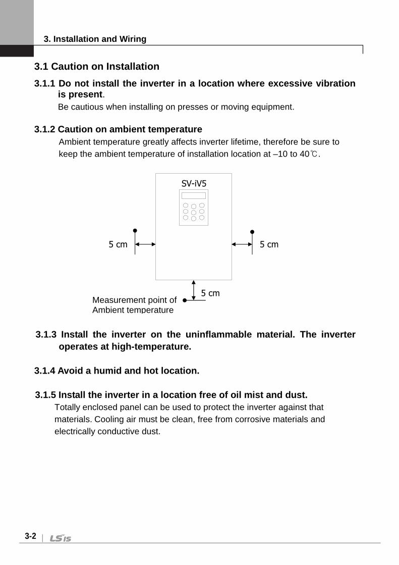
3.1.2 Caution on ambient temperature
Ambient temperature greatly affects inverter lifetime, therefore be sure to keep the ambient temperature of installation location at –10 to 40.
3.1.3 Install the inverter on the uninflammable mat erial. The inverter operates at high-temperature.
3.1.4 Avoid a humid and hot location.
3.1.5 Install the inverter in a location free of oi l mist and dust.
Totally enclosed panel can be used to protect the inverter against that materials. Cooling air must be clean, free from corrosive materials and electrically conductive dust.
Measurement point of Ambient temperature
5 cm
5 cm
5 cm
SV-iV5

3. Installation and Wiring
3-3
3.1.6 Secure the installation space enough to prote ct the inverter against the overheating.
At least the room that 30 cm from upper and lower of inverter and 20 cm from left and right of inverter is required for installing more than 30 kW products.
3.1.7 Special care should be taken in case the inve rter is to be installed in
the panel. In case more than 2 inverters are to be installed or ventilation fan is to be installed in the panel, make sure that inverter and ventilation fan is properly installed. If they are poorly installed, it causes the increase of an ambient temperature and less effective ventilation. Therefore, be sure to keep the ambient temperature of inverter below the allowable temperature.
3.1.8 Install the inverter tightly not to get loose using proper sized bolt or
screw.
Min. 5 cm
Min. 10 cm
Min. 5cm
SV-iV5
Min. 10 cm
3. Installation and Wiring
3-4
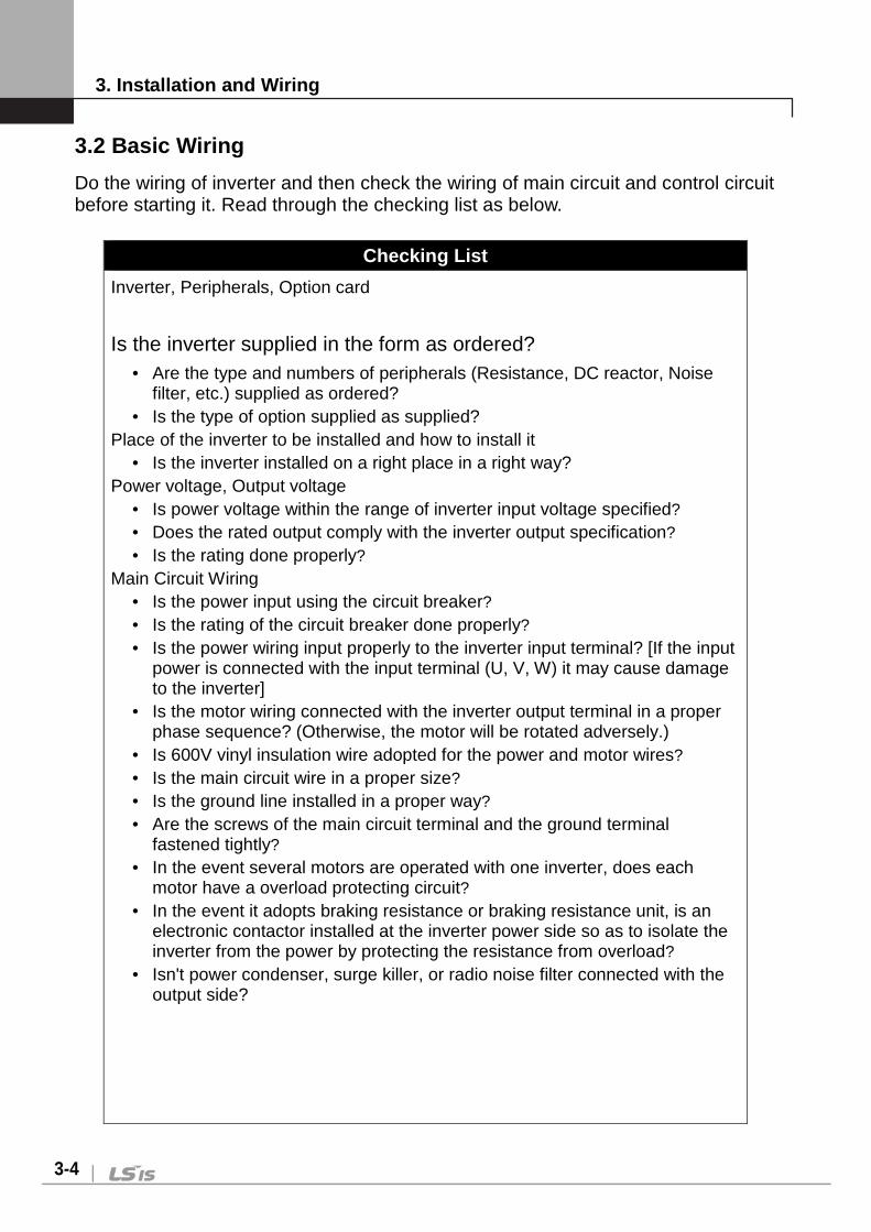
3.2 Basic Wiring
Do the wiring of inverter and then check the wiring of main circuit and control circuit before starting it. Read through the checking list as below.
Checking List
Inverter, Peripherals, Option card
Is the inverter supplied in the form as ordered?
Are the type and numbers of peripherals (Resistance, DC reactor, Noise filter, etc.) supplied as ordered?
Is the type of option supplied as supplied? Place of the inverter to be installed and how to install it
Is the inverter installed on a right place in a right way? Power voltage, Output voltage
Is power voltage within the range of inverter input voltage specified? Does the rated output comply with the inverter output specification? Is the rating done properly?
Main Circuit Wiring Is the power input using the circuit breaker? Is the rating of the circuit breaker done properly? Is the power wiring input properly to the inverter input terminal? [If the input
power is connected with the input terminal (U, V, W) it may cause damage to the inverter]
Is the motor wiring connected with the inverter output terminal in a proper phase sequence? (Otherwise, the motor will be rotated adversely.)
Is 600V vinyl insulation wire adopted for the power and motor wires? Is the main circuit wire in a proper size? Is the ground line installed in a proper way? Are the screws of the main circuit terminal and the ground terminal
fastened tightly? In the event several motors are operated with one inverter, does each
motor have a overload protecting circuit? In the event it adopts braking resistance or braking resistance unit, is an
electronic contactor installed at the inverter power side so as to isolate the inverter from the power by protecting the resistance from overload?
Isn't power condenser, surge killer, or radio noise filter connected with the output side?

3. Installation and Wiring
3-5
Checking List
Control Circuit Wiring
Is a twisted pair shielded wire adopted for the inverter control circuit wiring? Is the covered wire with shield connected with the ground terminal? In the event it is operated in 3-Wire sequence, is the control circuit wiring
done after the parameter of multi-function contact input terminal is modified?
Is the wiring of the optional devices done properly? Aren't there any wiring mis-connected? Are the inverter control circuit terminal screws fastened tightly? Aren't there any wire fragments or screw left? Doesn't the remaining wire connected with the terminal contact the
terminals nearby? Is the control circuit wiring isolated from the main circuit wiring in the duct
or control panel? Doesn't the length of wiring exceed 300m ? (In the case of the produce of
3.7kW or less, the entire length of wiring should be 100m or less) Doesn't the wiring of safety input exceed 30m?

3. Installation and Wiring
3-6
AC Power Input Type SV022, 037, 055, 075, 110, 150, 185, 220iV5-2(DB) SV022, 037, 055, 075, 110, 150, 185, 220iV5-4(DB)
Note 1) It is used when inverter control circuit is energized from auxiliary power source (220 VAC) separated from main power supply. Use insulated transformer to separate from main power supply. (Transformer capacity: Above 100VA recommended) Only 11~22kW-2(Press) and 5.5~22kW-4(Press/Mold) supported (Other products will be released later.)
Main Power Circuit
Control Circuit

3. Installation and Wiring
3-7
AC Power Input Type SV300, 370iV5-2 SV300, 370, 450, 550, 750, 900, 1100, 1320, 1600, 2200, 2800, 3150, 3750iV5-4 Note: AC Fans for 300~2200iV5-4 series should be changed the input power
source of transformer 1st tap corresponding with that of inverter. (Factory default is 380VAC)
Note 1) It is used when inverter control circuit is energized from auxiliary power
source (220 VAC) without main power supply. Use insulated transformer to separate from main power supply. (Transformer capacity: above 100VA recommended)
Main Power Circuit
Control Circuit

3. Installation and Wiring
3-8
AC Power Input Type SV5000iV5-4
Note: AC220V (50/60 Hz) must be supplied to FAN1 and FAN2 because 500kW-4 type of inverter has an AC fan of 220V internally. If not use AC220V power, the inverter is not operated because of ‘FAN PWR’ until the trip is released after inputting of AC220V. The order of power supply is described as below.
(The order of power on: 220VAC for fan Main power source of 3-phase AC input Run) (The order of power off: Stop Main power source of 3-phase AC input 220VAC for fan)
Note 1) It is used when inverter control circuit is energized from auxiliary power
source (220 VAC) without main power supply. Use insulated transformer to separate from main power supply. (Transformer capacity: above 100VA recommended)
Main Power Circuit
Control Circuit
3. Installation and Wiring
3-9
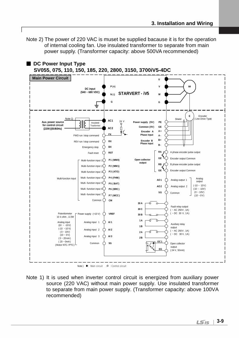
Note 2) The power of 220 VAC is muset be supplied bacause it is for the operation of internal cooling fan. Use insulated transformer to separate from main power supply. (Transformer capacity: above 500VA recommended)
DC Power Input Type
SV055, 075, 110, 150, 185, 220, 2800, 3150, 3700iV5-4DC
PE
P (+)
N (-)
U
V
W
FX
P1 (MM0)
P2 (MM1)
P3 (ATO)
CM
VREF
AI 1
5G
IM
GE
A +
RA
GE
RB
E
GE
Multi- function input 1
Multi- function input 2
Multi- function input 3
Common
Potentiometer10 k ohm , 1/ 2W
Multi-function input
G
Encoder APhase input
Note ) : Main circuit , : Control circuit
Shield
P4 (FHM )
P5 ( BAT)
P6 (BRC )
P7 (MCC )
STARVERT - iV5
Multi - function input 4
Multi - function input 5
Multi - function input 6
Multi - function input 7
AI 2
AI 3
Power supply (+10 V)
Analog input 1
Analog input 2
Analog input 3
Common
Analog input(10 ~ -10V)(-10 ~10 V)
( 0 ~ 10V)(10 ~ 0V)
( 0 ~ 20mA )( 20 ~ 0mA )
(Motor NTC / PTC)
Encoder BPhase input
Power supply (5V)
Common (0V)
Open collectoroutput
AO 1
AO 2
5G
Analog output 1
Analog output 2
Common
Analogoutput
( -10 ~ 10V)(10 ~ -10V)(0 ~ 10V)(10 ~ 0V)
30 A
30 C
30 B
1A
1B
2B
2A
Fault relay output( ~ AC 250V, 1A)( ~ DC 30 V, 1A)
Auxiliary relayoutput( ~ AC 250V, 1A)( ~ DC 30 V, 1A)
Open collectoroutput( 24 V, 50mA)
OC 1
EG
B+
A -
B -
A phase encoder pulse output
B phase encoder pulse output
Encoder output Common
Encoder output Common
AC1
AC2
Aux. power sourcefor control circuit
InsulatedTrasformer
Note 1)
RX
BX
RST
FWD run /stop command
REV run / stop command
Emergency stop
Fault reset
24 V
(50/60Hz)(220V)
Encoder( Line Drive Type)
DC input(540 ~ 680 VDC)
G
Note 1) It is used when inverter control circuit is energized from auxiliary power
source (220 VAC) without main power supply. Use insulated transformer to separate from main power supply. (Transformer capacity: above 100VA recommended)
Main Power Circuit
3. Installation and Wiring
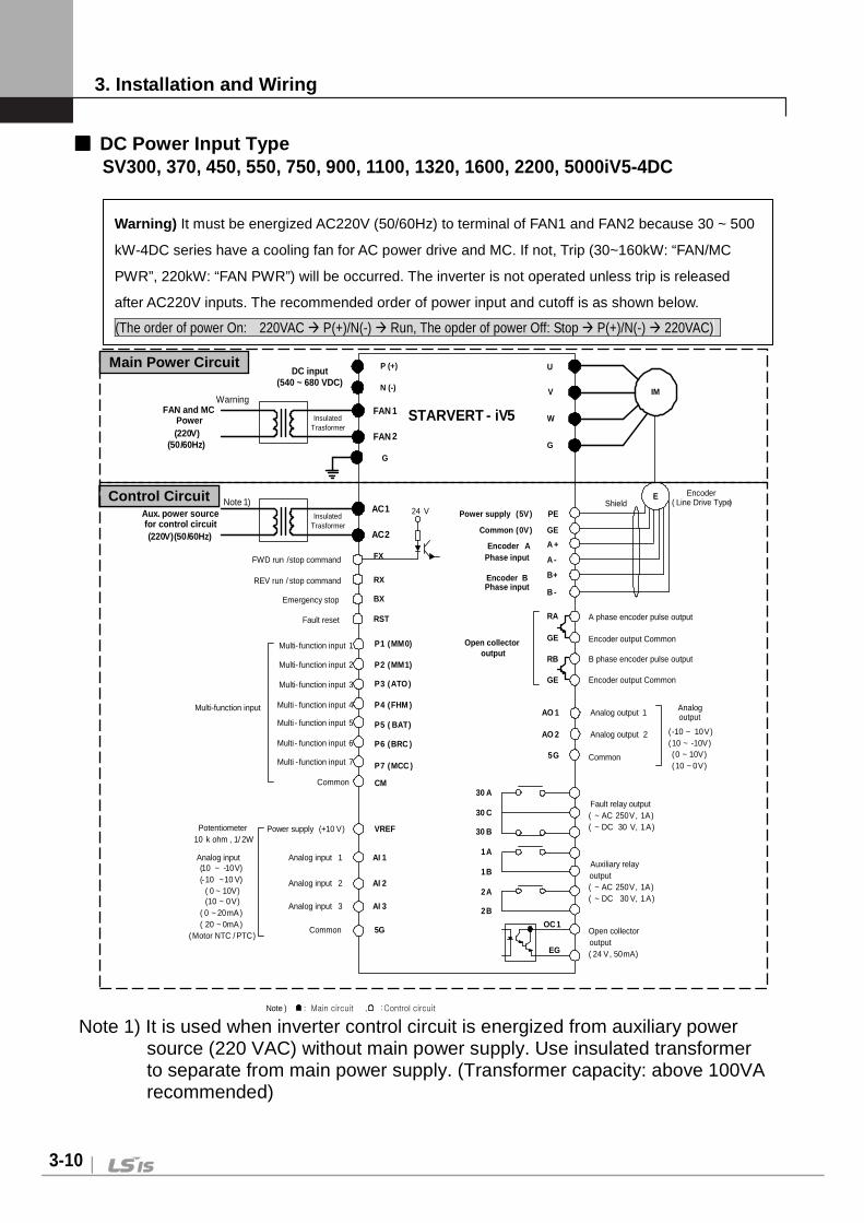
3-10
DC Power Input Type SV300, 370, 450, 550, 750, 900, 1100, 1320, 1600, 2200, 5000iV5-4DC
PE
P (+)
N (-)
U
V
W
FX
P1 (MM0)
P2 (MM1)
P3 (ATO)
CM
VREF
AI 1
5G
IM
GE
A +
RA
GE
RB
E
GE
Multi- function input 1
Multi- function input 2
Multi- function input 3
Common
Potentiometer10 k ohm , 1/ 2W
Multi-function input
G
Encoder APhase input
Note ) : Main circuit , : Control circuit
Shield
P4 (FHM )
P5 ( BAT)
P6 (BRC )
P7 (MCC )
STARVERT - iV5
Multi - function input 4
Multi - function input 5
Multi - function input 6
Multi - function input 7
AI 2
AI 3
Power supply (+10 V)
Analog input 1
Analog input 2
Analog input 3
Common
Analog input(10 ~ -10V)(-10 ~10 V)
( 0 ~ 10V)(10 ~ 0V)
( 0 ~ 20mA)( 20 ~ 0mA)
(Motor NTC / PTC)
Encoder BPhase input
Power supply (5V)
Common (0V)
Open collectoroutput
AO 1
AO 2
5G
Analog output 1
Analog output 2
Common
Analogoutput
( -10 ~ 10V)(10 ~ -10V)(0 ~ 10V)(10 ~ 0V)
30 A
30 C
30 B
1A
1B
2B
2A
Fault relay output( ~ AC 250V, 1A)( ~ DC 30 V, 1A)
Auxiliary relayoutput( ~ AC 250V, 1A)( ~ DC 30 V, 1A)
Open collectoroutput( 24 V, 50mA)
OC 1
EG
B+
A -
B -
A phase encoder pulse output
B phase encoder pulse output
Encoder output Common
Encoder output Common
AC1
AC2
Aux. power sourcefor control circuit
InsulatedTrasformer
Note 1)
RX
BX
RST
FWD run /stop command
REV run / stop command
Emergency stop
Fault reset
24 V
(50/60Hz)(220V)
Encoder( Line Drive Type)
DC input(540 ~ 680 VDC)
FAN 1
FAN 2
InsulatedTrasformer
WarningFAN and MC
Power
(50/60Hz)(220V)
G
Note 1) It is used when inverter control circuit is energized from auxiliary power source (220 VAC) without main power supply. Use insulated transformer to separate from main power supply. (Transformer capacity: above 100VA recommended)
Warning) It must be energized AC220V (50/60Hz) to terminal of FAN1 and FAN2 because 30 ~ 500
kW-4DC series have a cooling fan for AC power drive and MC. If not, Trip (30~160kW: “FAN/MC
PWR”, 220kW: “FAN PWR”) will be occurred. The inverter is not operated unless trip is released
after AC220V inputs. The recommended order of power input and cutoff is as shown below.
(The order of power On: 220VAC P(+)/N(-) Run, The opder of power Off: Stop P(+)/N(-) 220VAC)
Control Circuit
Main Power Circuit

3. Installation and Wiring
3-11
Note 2) The power of 220VAC is must be supplied for the operation of internal cooling fan and/or Magnetic contactor. Use insulated transformer to separate from main power supply. (30 ~ 160 kW: for the operation of FAN and MC, 220/500kW: for the operation of FAN) (Transformer capacity: above 30~75kW(100VA), 90~160kW(150VA), 220/500kW(500VA) recommended )
3.3 Power Circuit Terminal 3.3.1 Power circuit terminal arrangement
(1) AC power input type
CAUTION
Be sure that “N” is not Neutral Line but DCN(-) and P is DCP(+).
SV022, 037, 055, 075, 110, 150, 185, 220iV5-2(DB)
SV022, 037, 055, 075, 110, 150, 185, 220iV5-4(DB)
R S T U V W G N(-) B2 B1 P(+)
SV110, 150, 185, 220iV5-2(DB)(MD)
SV110, 150, 185, 220iV5-4(DB)(MD ) *(MD) : Mold Type
R S T U V W N(-) B2 B1 P(+)
SV300, 370iV5-2
SV300, 370, 450, 550, 750iV5-4
R S T G U V W P1(+) P2(+) N(-)
G

3. Installation and Wiring
3-12
SV900, 1100, 1320, 1600, 2200iV5-4
R S T G U V W P1(+) P2(+) N(-)
SV2800, 3150, 3750, 5000 iV5-4
R(L1) S(L2) T(L3) P1(+) P2(+) N(-) G U V W
(2) DC power input type SV055, 075iV5-4DC
U V W N(-) P(+) G
SV110, 150, 185, 220iV5-4DC
G U V W P(+) N(-)
SV300, 370,450,550,750,900,1100,1320,1600,2200iV5-4DC
FAN1 FAN2
SV2800, 3150, 3750, 5000iV5-4DC
P(+) N(-) U V W G
G U V W P(+) N(-)

3. Installation and Wiring
3-13
3.3.2 Power circuit terminal description
(1) AC power input type Name Function Description
R, S, T 3 Phase input power supply
Connected to 3 phase input power supply
U, V, W Inverter Output Connected to 3 phase induction motor
G Grounding Used for inverter frame earth
B1, B2 Braking Resistor Connected to braking resistor
P1(+), P2(+)
DC Reator and DB Unit
Used for DC Reactor, DB Unit and DC link common connection
P(+) DC Link common DC link common connection
N(-) DB Unit Used for DB Unit and DC link common connection
(2) DC power input type
Name Function Description
P(+), N(-)
DC input power Connected to DC input power source Connected from DC power suupy (PWM converter) within max. 30m
U, V, W Inverter Output Connected to 3-phase induction motor
G Grounding Used for inverter frame earth
FAN1, FAN2
Internal cooling fan and MC drive power source
Connected to single-phase 220V AC power source note1)
Note 1) In case of 500kW product, it is applied at AC input type.
3.3.3 Cautions to be required for wiring to power c ircuit terminal ① Connect terminals (R, S and T) to 3 phase input power supply after checking
inverter nameplate attached on the inverter. Never connect terminals (U, V and W) to 3 phase input power supply. It results in lethal damage to the inverter. Input
Voltage
R S T G U V W

3. Installation and Wiring
3-14
② Never connect the phase advancing capacitor to the inverter output. If already installed, remove the phase advancing capacitor clearly.
③ Cable between inverter output and motor should be less than 30m long. If cable gets
long, surge voltage appears across motor terminals depending on the cable parameters. Especially, in 400V class motor case, insulation withstanding voltage may be decreased. Use an insulation-enforced motor when 400V class motor is used.
Distance between inverter and motor Up to 50m Up to 100m Over 100m
Permitted Carrier Frequency Below 10kHz Below 5kHz
Below 2.5kHz
(In case of below 3.7 kW, use the cable of output within 100 m)
④ Crimp terminal with insulation cap should be used for the input power supply and the motor.
⑤ After finishing wiring, be certain to remove all the wire or cable scraps inside the inverter.
⑥ Use the shield cable or twist-paired wire for control circuit terminal. Do not put them into the same wiring duct for the power terminal.
⑦ When wiring is changed after operating the inverter, be sure to check LCD window on the keypad or charge lamp is turned off. Capacitors inside inverter are charged with high voltage and it may result in lethal injury.
⑧ Below 22kW inverter, B1 and B2 on the power terminal should not be connected to anything else other than DB resistors.
Phase
advancing capacitor
SV-iV5

3. Installation and Wiring
3-15
3.3.4 Main power circuit wire sizes and grounding w ire size ① Main Power Circuit Wire Sizes
If wiring for the main power terminal is not performed properly, it may cause severe damage to inverter or lethal injury to inverter operator. (Standards of IEC 60227-3 or UL508C)
Inverter Capacity
Wire Size
mm 2 AWG or kcmil
R, S, T U, V, W R, S, T U, V, W
200V
2.2 kW 2.5 2.5 12 12
3.7 kW 4 4 10 10
5.5 kW 6 6 8 8
7.5 kW 10 10 6 6
11 kW 16 16 4 4
15 kW 25 25 3 3
18.5 kW 35 35 2 2
22 kW 35 35 2 2
30 kW 50 50 1/0 1/0
37 kW 70 70 2/0 2/0
400V
2.2/3.7 kW 2.5 2.5 12 12
5.5 kW 4 4 10 10
7.5 kW 4 4 10 10
11 kW 6 6 8 8
15 kW 10 10 6 6
18.5 kW 16 16 4 4
22 kW 16 16 4 4
30 kW 35 25 3 3
37 kW 25 25 3 3
45 kW 50 35 2 2
55 kW 50 50 1 1
75 kW 70 70 2/0 2/0
90 kW 120 120 4/0 4/0
110 kW 150 150 300 300
132 kW 185 185 350 350

3. Installation and Wiring
3-16
Inverter Capacity
Wire Size
mm 2 AWG or kcmil
R, S, T U, V, W R, S, T U, V, W
160 kW 240 240 500 500
220 kW 400 400 800 800
280 kW 2 X 240 2 X 240 2 X 500 2 X 500
315 kW 2 X 240 2 X 240 2 X 500 2 X 500
375 kW 2 X 300 2 X 300 2 X 600 2 X 600
500 kW 2 x 400 2 x 400 2 x 800 2 x 800
1) Apply the rated torque to terminal screws. Loose screws can cause of short circuit or malfunction. Tightening the screws too much can damage the terminals and cause a short circuit or malfunction.
② Grounding Wire Size and Caution to be taken Be sure to ground the motor and the inverter to prevent electric shock injury.
(200V class: ground impedance 100Ω, 400V class: ground impedance 10Ω) Connect the inverter ground to the ground terminal exclusively used for the
inverter. Do not use the case of inverter of sash screw for ground. It is strongly recommended that as thick a grounding wire as possible be
used and wire be short.
Motor Capacity Ground wire size( mm²)
200V Class 400V Class
2.2 ~ 3.7 kW 4 2.5
5.5 ~ 7.5 kW 6 4
11 ~ 15 kW 16 10
18.5 ~ 22 kW 25 16
30 ~ 37 kW 25 16
45 ~ 75 kW - 25
90 ~ 132 kW - 35
160 ~ 220 kW - 95
280 ~ 315 kW - 185
375 ~ 500 kW - 240

3. Installation and Wiring
3-17
3.3.5 Wiring DC Reactor (Option) (AC power input: 3 0kW and higher) 3.3.6 Wiring DB Unit (Option) (AC power input: 30kW and higher)
3.3.7 Wiring guide when using both of DC reactor (O ption) and DB
Unit(option) (AC power input: 30kW and higher)
DC Reactor P1(+) P2(+)
G U V W N
P1(+)P2(+)N(-)
DB resistor
DB UNIT
P/B1 N B2 G
G U V
P1 P2 N
DB resistor
DB UNIT
DC Reactor
G U V W
G N B2 P/B1

3. Installation and Wiring
3-18
3.4 Control Board and Terminal 3.4.1 Control circuit terminal arrangement SV022 ~ 5000iV5

3. Installation and Wiring
3-19
3.4.2 Control circuit terminal function description
Item Name Function Description
Con
tact
Inpu
t
FX Forward Run/Stop
Command Forward/Reverse RUN Command is ON
when closed to CM in NPN input mode. Motor stops when FX/RX is ON or OFF at the
same time. RX Reverse Run/Stop
Command
BX Emergency Stop ON when closed to CM in NPN input mode,
Free-run to Stop and deceleration to stop. It does not trigger fault alarm signal.
RST Fault Reset Resets when fault condition is cancelled.
P1 (MM0)
Multi-function input contact
A function can be selected among 46 different functions as shown below. (Multi-step speed 1 / 2 / 3, Jog, MOP Up / Down / Save / Clear, Analog Hold, Main Drive, 2nd function, Accel./Decel. Time selection, 3 Wire RUN, External trip (B contact), Power failure prevention, Reverse rotation prevention, Process PI Disable, Timer input, Soft start cancel, ASR P/PI Gain switch-over, ASR P/PI switch-over, Flux command value switch-over, Pre-excitation, Speed/Torque control, Torque limit ON/Off, Torque bias ON/Off, Battery operation On/Off, Low voltage trip detection prevention, etc.)
P2 (MM1)
P3 (AT0)
P4 (FHM)
P5 (BAT)
P6 (BRC)
P7 (MCC)
CM COMMON
In NPN input mode, it turns On when each contact is closed to CM terminal.
In PNP input mode, it turns On when each contact is closed to external 24V input.
Ana
log
Inpu
t VREF Power supply for
analog setting Reference voltage by variable resistor ( +
10V ) : 10kΩ
AI1 Voltage/ Current
Signal Input Voltage input (-1010V, 10-10V, 010V,
100V)

3. Installation and Wiring
3-20
Item Name Function Description
AI2 Motor NTC is selectable function. Jumper setting in Voltage Input: Jumper set
as default) AI1, AI2: Jumper set on left side,
AI3: Switch set on left(“V”) side Jumper setting in Current Input AI1, AI2: Jumper set on right side S/W setting in motor NTC (Higen motor) AI3: switch set on right (“Them”) side. Selectable 17 functions as following: (Speed, Process PID controller, Process PI
controller feedback, Draw, Torque, Magnetic flux, Torque bias, Torque limit, Motor NTC, etc.)
AI3/ Them
Voltage input Motor NTC Input
5G COMMON COMMON terminal for Analog input
Enc
oder
Inpu
t
PE P/S (Power supply) for Pulse
Encoder
+5V Line Drive Power
GE 0V
A+ Encoder A-phase signal
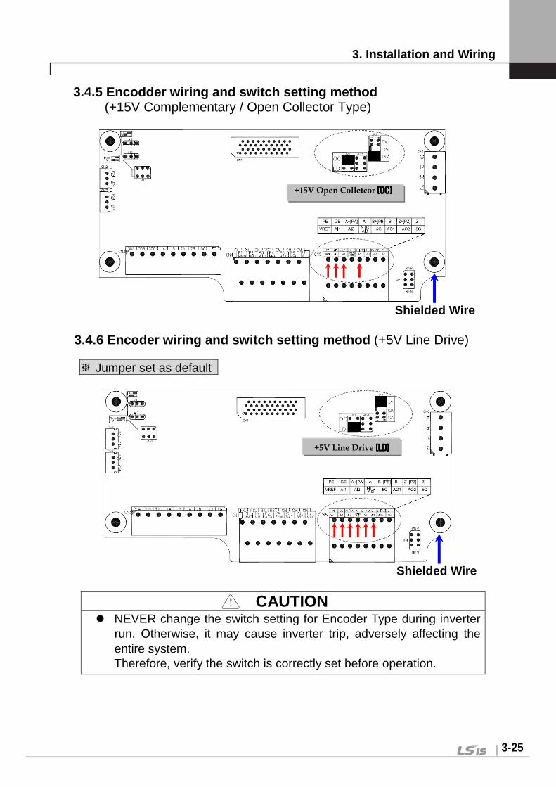
A, B signal for Line Drive Type Encoder. Set the JP2 switch at “P5” on I/O PCB and
set the JP4 switch to “LD” for the use of Line Drive.
※※※※ Jumper set as default
A-
B+ Encoder B-phase signal B-
PE P/S for Open Collector
+15V Open Collector Power
GE 0V
PA Encoder
A-phase signal
A, B signal for Complementary or Open Collector Type Encoder.
Set the JP2 switch at “P15” on I/O PCB and set the JP4 switch to “OC” for the use of Open Collector.
PB Encoder
B-phase signal
Z+ (PZ)
Encoder Z-phase signal
Caution) The usages of Z-phase signal are as follows and its functions will be available soon.
Use for Z-phase pulse provided encoders. Z+ and Z- signals are used for Line Drive
type, so set the JP5 switch to “LD”. PZ signal is used for Open Collector type, so
set the JP5 switch to “OC”.
Z-

3. Installation and Wiring
3-21
Item Name Function Description
Enc
oder
Out
put RA
Encoder signal output : A-phase
Encoder A, B phase signal output – Open Collector Type Note1)
GE Output Common
RB Encoder signal output : B-phase
GE Output Common
Ana
log
Out
put
AO1 Analog Output 1
-10V 10V, 10 -10V, 0 10V, 10 0V output
Selectable among 39 functions (Analog input value, Pre Ramp Reference, Post ramp reference, ASR Input Reference, Motor Rotating Speed, Speed Deviation, ASR Output, Torque bias, Positive Trq Limit, Negative Trq Limit, Regeneration Trq Limit, Torque Reference, Torque current ref., Torque current, Flux reference, Flux Current ref. , Flux Current, ACR output of axis Q, ACR output of axis D, Voltage reference of axis D, Voltage reference of axis Q, Output current, Output voltage, Output power, DC LINK voltage, Process PI reference, Process PI Feedback, Process PI output, Motor temperature, Motor temperature, Inverter temperature, Inverter i2t)
AO2 Analog Output 2
5G COMMON COMMON terminal for Analog Output
Rel
ay O
utpu
t
1A Multi-function relay output 1 (A Contact)
Selectable among the following 22 functions; (Inverter ready, Zero speed detection, Seed detection, Speed detection (ABS), Speed arrival, Timer out, Low voltage alarm, run, regenerating, Motor overheat warning, Inverter overheat warning, Speed agree, Torque detection, Torque limit detection, Overload warning, Stop, Steady run, Brake output, WEB brake, UP to speed, False core, MC output)
1B
2A Multi-function relay output 2 (A Contact) 2B
OC1 Open Collector
Output EG
30A Fault alarm A contact
Outputs when fault occurs. Deactivated in BX condition.
3. Installation and Wiring
3-22
Item Name Function Description
30B Fault alarm B contact
30C COMMON COMMON for A, B
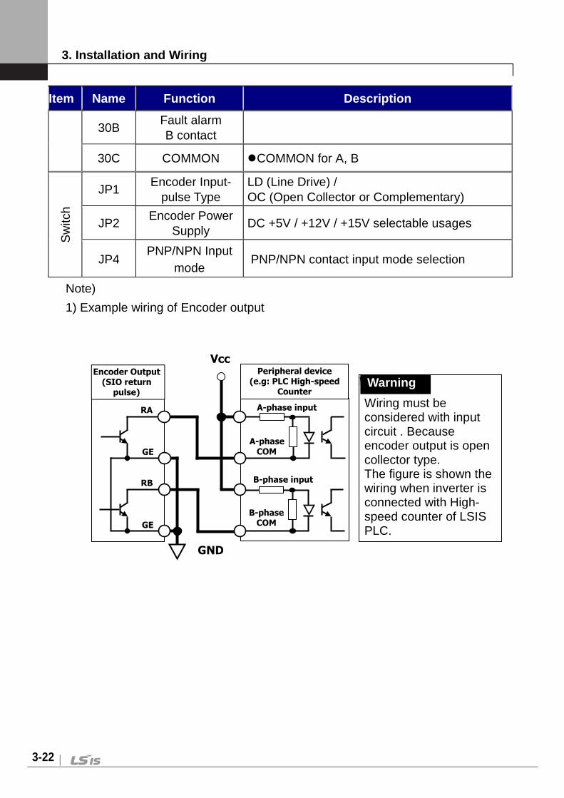
Sw
itch
JP1 Encoder Input-
pulse Type LD (Line Drive) / OC (Open Collector or Complementary)
JP2 Encoder Power Supply
DC +5V / +12V / +15V selectable usages
JP4 PNP/NPN Input mode
PNP/NPN contact input mode selection
Note)
1) Example wiring of Encoder output
Warning!
Wiring must be considered with input circuit . Because encoder output is open collector type. The figure is shown the wiring when inverter is connected with High-speed counter of LSIS PLC.
Vcc
Encoder Output (SIO return
pulse)
RA
GE
RB
GE
Peripheral device (e.g: PLC High-speed
Counter
A-phase input
A-phase COM
B-phase input
B-phase COM
GND
Warning

3. Installation and Wiring
3-23
Additional Functions of Extended I/O(EXTN _ I/O) Co ntrol board terminal
Item Name Function Description
Ana
log
Inpu
t
AI1 Voltage Input Current Input
Extended I/O(EXTN_I/O) board is added analog input AI4, AI5.
How to use terminal Pin : - Voltage Input : AI1, AI2,AI3, AI4, AI5
- Current Input : AI1, AI2, AI3, AI4 - Motro NTC input : AI5
Note) Jumper setting and functions are explained at I/O control terminal description.
AI2
AI3
AI4
AI5/ Them
Voltage Input Motor
NTC Input
5G COMMON COMMON terminal for Analog Input

3. Installation and Wiring
3-24
3.4.3 Wiring the control circuit terminal
① Shield wire or vinyl insulated wire are highly recommended to be used for
the control circuit terminal. ② Be sure to use twisted shield wire if wiring distance gets too long. ③ Wire should be at least as thick as 0.2 ~ 0.8 mm2 (18 ~ 26 AWG). ④ Screwing torque limit should be kept under 5.2 lb-in. ⑤ Maximum interrupting capacity of auxiliary contact 1, 2 is of AC 250V/1A, DC
30V/1A. ⑥ Maximum interrupting capacity of fault alarm relay A, B contact is of AC
250V/1A, DC 30V/1A. ⑦ Open collector output 1, 2, 3 and encoder output can be used below
maximum of 24V/100mA. ⑧ Wires for the control circuit terminal should be separated from ones for the
power circuit terminal, if possible and in case wires for both control circuit terminal and the power circuit one cross each other, they should be crossed at right angles (90°).
3.4.4 Caution on wiring pulse encoder
1) Check-up of the coupling and alignment of motor and encoder shaft ① Be sure to mount the pulse encoder at the location where it rotates at the
same speed as the motor does. (e.g. on the opposite shaft of load side of motor, on the opposite shaft of motor at traction machine)
② In case there is speed slip between the motor shaft and encoder shaft, the motor may not start or it causes mechanical vibration.
③ Poor alignment of motor and encoder shaft results in torque ripple and causes mechanical vibration which has the same frequency as the motor speed at the constant speed region.
2) Wiring the pulse encoder ① Be sure to use twist paired shield wire and ground shield wire to screw for
earth on the I/O PCB. ② Signal wires should be separated from the power lines, if possible.
Electromagnetic noise may affect the pulse encoder output signals.
Wires for Control Circuit Min. distance : 10cm
Wires for Main Circuit
Min. distance : 10cm
3. Installation and Wiring
3-25
3.4.5 Encodder wiring and switch setting method (+15V Complementary / Open Collector Type)
Shielded Wire
3.4.6 Encoder wiring and switch setting method (+5V Line Drive)
※ Jumper set as default
Shielded Wire
CAUTION
NEVER change the switch setting for Encoder Type during inverter run. Otherwise, it may cause inverter trip, adversely affecting the entire system. Therefore, verify the switch is correctly set before operation.
+5V Line Drive (LD)(LD)(LD)(LD)
+15V Open Colletcor (OC)(OC)(OC)(OC)
3. Installation and Wiring
3-26
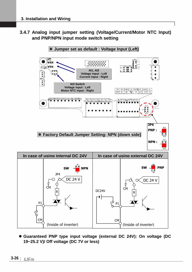
3.4.7 Analog input jumper setting (Voltage/Current/Motor NTC Input) and PNP/NPN input mode switch setting
※※※※ Jumper set as default : Voltage Input (Left)
※※※※ Factory Default Jumper Setting: NPN (down side) Guaranteed PNP type input voltage (external DC 24V) : On voltage (DC
19~25.2 V)/ Off voltage (DC 7V or less)
AI1, AI2 Voltage input : Left
Current input : Right
AI3 Switch Voltage input : Left
Motor NTC input : Right
DC 24 V
P1
CM
CM
JP4
NPN SW JP4
R
(Inside of inverter)
P1
CM
CM DC24V
(Inside of inverter)
R
DC 24 V
PNP SW
JP4
In case of using i nternal DC 24V In case of using external DC 24V
JP4
PNP :
NPN :

3. Installation and Wiring
3-27
CAUTION NEVER change the jumper setting during inverter run. Otherwise, it may
cause inverter trip, adversely affecting the entire system. Motor NTC input for Analog Input 3 (AI3) is ONLY available when OTIS
Motor is connected. If user use a motor other than Higen motor with different NTC specification and use this function, it will lead to motor overheat and damage to the motor.
Do not change the setting of PNP/NPN input switch during inverter operation. It can influence to the system since contact input is changed. Set the switch correctly before inverter operation.
3.5 Terminal of the Auxiliary Power Supply 3.5.1 The position of the terminal SV055 ~ 075iV5-4(Press) (for AC products) SV110 ~ 750iV5(Press) (for AC/DC products)
Terminal of the Auxiliary Power Supply

3. Installation and Wiring
3-28
SV055 ~ 075iV5-4(Mold)
SV110 ~ 220iV5-4(Mold)
SV900 ~ 2200iV5(Press) (for AC/DC products)
Terminal of the Auxiliary Power Supply
Terminal of the Auxiliary Power Supply

3. Installation and Wiring
3-29
SV2800 ~ 5000iV5(Press) (for AC/DC products)
3.5.2 Function description of auxiliary terminal bl ock Symbol Terminal Name Terminal Description Input Power
AC1, C2 Auxiliary power
input Inputs single-phase AC input source
220V (-10 ~ +10%), 50/60Hz
3.5.3 Wiring and Precaution of auxiliary terminal b lock ① Connect the auxiliary power supply through insulated transformer separated
with main power supply. ② User polyvinyl chloride insulated wire for auxiliary power cable. ③ Use the cable above 0.5mm2 (20 AWG).
Terminal of the Auxiliary Power Supply

4. Trial Operation
4-1
Chapter 4 - Trial Operation 4.1 Keypad Operation LCD Keypad can display up to 32 alphanumeric characters and monitor or set parameter values to operate the inverter and the motor properly. As follows are keypad view and explanation on each key/LED on the keypad.
<Keypad View>
Items Name Function Description
Key
MODE Mode Enables to move to the other groups (Initial Screen →DIO → PAR → FUN…) and go to the first code in the same group.
PROG Program Enables to modify setting values.
ENT Enter Enables to move to the other groups (Initial Screen ← DIO ← PAR ← FUN…) and save the changed setting values.
(Up) Up Moves to the next code or increments setting values. (Down) Down Moves to the next code or decrements setting values.
SHIFT/ESC Shift/ESC Acts as Shift key in a setting mode and as ESC key in other mode.
REV Reverse RUN
Reverse RUN command is enabled.
STOP/ RESET
Stop/Reset Stop key during inverter operation. Resets fault when inverter returns to normal after fault has occurred.
FWD Forward RUN
Forward RUN command is enabled.
LED
(REV) Reverse RUN
Lit when motor is in reverse revolution. Blinks on acceleration/deceleration, lit in a constant speed.
(STOP/RESET) Stop/Reset Lit when the motor stops. Blinks when fault has occurred.
(FWD) Forward RUN
Lit when motor is in forward revolution. Blinks on acceleration/deceleration, lit in a constant speed.
0.0rpm SPD Tq 0.0% 0.0A

4. Trial Operation
4-2
4.2 Keypad LCD Display 4.2.1 LCD Start-up display
No. Function Description
1 Motor speed Real motor speed in RPM (Revolution Per Minute)
2 Motor control Mode
SPD : Speed control mode TRQ : Torque control mode WEB : WEB control mode SLS : Sensorless control mode BX : Emergency stop BAT : Battery-operated mode
3 Generating torque Displays % ratio to the rated torque of a motor.
4 Output current Inverter output current in RMS 4.2.2 Group display
No. Function Description
1 Parameter group Displays the name of each parameter group. There are DIS, DIO, PAR, FUN, CON, AIO, USR and 2nd group, etc..
2 Code name Displays a code name to be set.
3 Code Number Displays a code number to be set.
4 Code data and unit Displays a code data and a code unit to be set.
0.0rpm SPD Tq 0.0% 0.0A
3 4
2 1
FUN Speed1
13 0.0rpm
3 4
2 1

4. Trial Operation
4-3
4.3 Setting of Parameter Values In case inverter is to be in use using a keypad, proper parameter values can be set depending on the load and operation condition. First, move on to the code in a group where is intended to change parameter value. Cursor () blinks by pressing [PROG] key. Parameter value can be set using (SHIFT/ESC)], [(Up)] and [(Down)] keys and then can be saved by entering [ENT] key. Note) In some cases, data will not be changed for the following two reasons. * Some data cannot be changed during inverter operation. * Parameter data lock function is set. (PAR_04 [Parameter Lock] is enabled) Example) In case the 1st acceleration time is to be changed from 10(sec) to
15(sec), it can be set as shown below.
FUN Acc Time-1
40 10.00 sec
FUN Acc Time-1
40 10.00 sec
FUN Acc Time-1
40 10.00 sec
FUN Acc Time-1
40 15.00 sec
FUN Acc Time-1
40 15.00 sec
0.0rpm SPD
Tq 0.0% 0.0A
FUN Jump code
00 1
FUN Jump code
00 40
Initial Display
Move to FUN Group by using [MODE] Key
Acc time 1 is settable.
Press [PROG] Key Enter 40 by [(SHIFT/ESC)], [(Up)], [(Down)] Key [ENT]
Press [PROG] Key.
Setting Mode(Cursor() appears and blinks)
Move the Cursor() to the position to be changed using
[(SHIFT/ESC)] key.
Set the data using [(Up)], [(Down)] key.
Save the changed data by pressing [ENT] key.
(Cursor disappears.)

4. Trial Operation
4-4
4.4 Data Groups SV-iV5 series inverters use LCD keypad for user’s convenience. Data groups are divided into 12 groups for easy access depending on the inverter application.
Name LCD keypad (on the upper left) Description
Display group DIS
Motor speed, Motor control mode, Generating torque, Output current, User selection display, Process PID output/reference/feed-back value, Fault display, User group display setting and so on.
Digital I/O group
DIO Digital Input /Output parameters and so on.
Parameter group PAR
Parameter initialization, Parameter read / write / lock /password, Constant which is motor related, Auto-tuning and so on.
Function group
FUN Operating frequency, Operation mode, Stop mode, Acceleration /deceleration time and pattern, Carrier frequency, Electronic thermal selection and so on.
Control group CON
Control mode, ASR PI gain, Process PID gain, Draw control setting, Droop control related constants, Torque control related constants, V/F control related constants and so on.
Exterior group EXT
Built-in 485 communication parameter and communication parameter when the exterior option board is installed.
Analog I/O group
AIO Analog Input /Output Parameter and so on.
User group USR User macro function, macro function save, macro function recall
2nd function group 2nd 2)
2nd motor control mode, 2nd motor accel./decel. time, 2nd motor parameters and so on.
Elevator group
E/L 2) It is displayed when EL_I/O option board is installed, Elevator operation function setting parameter and so on.
Synchronous group SYNC 2)
It is displayed when SYNC_I/O option board is installed. Synchronous operation function setting parameter and so on.
WEB group WEB 2) Diameter and Tension control setting parameter while WEB control.
Sensorless control group
SLS 2) Open Loop control setting parameter which is not using the position sensor as encoder, resolver and, etc..
1) Group name: It is displayed when option board is installed, Refer to the option manual for more details.
2) It is displayed when the option board is installed and CON (control) mode is changed to it. Refer to the user manual related to the option board.

4. Trial Operation
4-5
Group transfer in the keypad For transfer to another group, [MODE] key is used and (Up), (Down) key is used to move up and down in the same group.
Display group I/O group Parameter gro up Function group Control group
In these group transfers, User Group, 2nd Group, AIO Group, EXT group and
WEB Group are omitted.
MOD
E
MODE
0.0rpm SPD Tq 0.0% 0.0A
DIO Jump code 00 1
PAR Jump code 00 1
MOD
E
DIO P1 define 01 Not Used
PAR Para. init 01 --- No ---
FUN Run/Stop Src 01 Terminal 1
DIS Out Amps RMS 02 0.0 A
DIO P2 define 02 Not Used
PAR Para. read 02 --- No ---
FUN Spd Ref Sel 02 Analog
DIO P3 define 03 Not Used
PAR Para. write 03 --- No ---
FUN Stop mode 03 Decel
PIDOUT 0.0% * 0.0% 0.0%
DIO P4 define 04 Not Used
PAR Para. lock 04 0
FUN Max Speed 04 1800.0 rpm
DIS Faults 05 -------
DIO P5 define 05 Not Used
PAR Password 05 0
FUN Speed 0 12 0.0 rpm
DIO Lost Command 97 None
PAR Inertia LPF 38 0.100 ms
FUN AuxSpeedMod 85 Absolute
MODE MODE
MODE
FUN Jump code 00 1
MOD
E
MOD
E
MOD
E
MOD
E
DIS Power 03 0.0 kW
DIS Usr Grp Disp 06 Not Used
DIS Ai1 Value 01 0.0 %
MODE MODE
MODE MODE MODE
MODE MODE MODE MODE
MODE MODE MODE MODE
MODE MODE MODE MODE
MODE C
O
N
T
R
O
L
G
R
O
U
P
MODE

4. Trial Operation
4-6
4.5 Auto-Tuning Parameters such as stator resistance (Rs), stator leakage inductance (sL ), flux current (IF), rotor time constant (τr) and stator self-inductance (Ls) are indispensable for obtaining an excellent control performance in the vector control and are automatically measured and set using auto-tuning function. SV-iV5 features two types of Auto-tuning: 1) Rotational Auto Tuning
2) Standstill Auto Tuning 4.5.1 Motor and encoder parameter setting for auto- tuning
The Motor capacity, Basic speed, Rating voltage, Pole number, Efficiency, Rating slip and Rating current on the nameplate of the motor and the pulse number of encoder should be set before operation.
LCD Display Description
Enter the motor capacity. Basic capacity is same with Inverter capacity Enter directly in the PAR_08 after selecting “User Define” if there is no Motor capacity.
Enter the motor capacity directly at PAR_08
incase that select “User Define” at PAR_07.
Set the pulse numbers per revolution of pulse
encoder coupled to the motor shaft.
Set the motor base speed. Note) It is not rating current of name plate.
Base Speed = 120 X Base Frequency/ Pole number
Set the rated voltage of the motor.
(Voltage value on the name plate)
Set the number of poles of the motor.
Set the efficiency of the motor. If you cannot find the efficiency in name plate, Do not set the Efficiency.
Set the rated slip speed of the motor.
(Rated slip=synchronous speed–rated speed)
Set the rated current of the motor.
PAR Moto r se lec t 07 kW
PAR Base Speed 17 rpm
PAR Po le number 19 [ ]
PAR Ra ted Vo l t 18 V
PAR Rated -Curr 22 A
PAR Rated -S l ip 21 rpm
PAR Enc Pu lse 10 [ ] [ ] [ ]
PAR Eff ic iency 20 %
PAR UserMoto rSe l 08 kW

4. Trial Operation
4-7
4.5.2 Rotational auto-tuning
1) Precautions
CAUTION Be sure to remove the load connected to the motor shaft before performing rotational auto-tuning. Otherwise, it may lead to damage to the motor or bodily injury. DB resistor should be installed because the inverter repeats abrupt Accel/Decel many times to find the motor constant (Tr) during tuning.
2) Rotational Auto-tuning procedure
LCD Display Description Tuning Time
Set it to “ Rotational ”. -
Auto-tuning starts when it is set to “ ALL1 ”.
-
Checks whether the encoder wiring is properly done and an encoder works well by rotating the motor at 1500 rpm in forward direction.
30 ~ 35(Sec)
Stator resistance (Rs) is measured without rotating the motor.
10 ~ 20(Sec)
The leakage inductance (sL) of the motor is measured without rotating the motor.
5 ~ 20(Sec)
The flux current (IF) is measured by rotating the motor at 1500 rpm.
30 ~ 60(Sec)
Stator self-inductance (Ls) is measured by rotating the motor at 1500 rpm.
50 ~ 60(Sec)
PAR AutoTuneType 24 Ro ta t iona l
PAR Auto tuning 25 ALL1
PAR Auto tuning 25 Enc Tes t ing
PAR Auto tuning 25 Rs Tun ing
PAR Auto tuning 25 sL Tun ing
PAR Auto tuning 25 IF Tun ing
PAR Auto tuning 25 Ls Tun ing

4. Trial Operation
4-8
LCD Display Description Tuning Time
Accel/Decel is performed repeatedly to find motor constant (Tr) so that DB Resistor should be connected before starting tuning. Otherwise, “Over Voltage ” trip will occur.
20 ~ 60(Sec)
When auto-tuning is complete successfully, “None” is displayed. If error occurs during auto-tuning, “[][] Error” is displayed. In this case, verify motor parameters and encoder setting is done properly and redo the auto-tuning. If the problem persists, contact LS representative.
Total 3 ~ 5 (Min.) is
required
FWD/REV LED on keypad will blink during Auto-tuning. If setting PAR_24 (Auto tuning) to “ ALL2 ”, all procedure is same as “ALL1”
except Encoder Testing will be skipped. Motor constants of each can be selected and separately tuned.
(Encoder Test, Rs Tuning, Lsigma, Flux Curr, Ls Tuning, Tr Tuning) If encoder phase (A, B) or inverter output wiring is switched during Auto-tuning,
“ Enc AB Chgd ” message will be displayed. In this case, changing PAR_11 (Enc Dir Set) setting from “A Phase Lead” to “B Phase Lead” (or oppositely) will erase the need for changing the wiring.
PAR Auto tuning 25 Tr Tun ing
PAR Auto tuning 25 None
PAR Auto tuning 25 [ ] [ ] E r ro r
4. Trial Operation
4-9
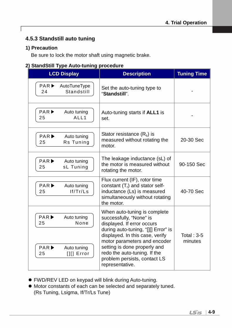
4.5.3 Standstill auto tuning
1) Precaution Be sure to lock the motor shaft using magnetic brake.
2) StandStill Type Auto-tuning procedure
LCD Display Description Tuning Time
Set the auto-tuning type to “Standstill ”. -
Auto-tuning starts if ALL1 is set. -
Stator resistance (Rs) is measured without rotating the motor.
20-30 Sec
The leakage inductance (sL) of the motor is measured without rotating the motor.
90-150 Sec
Flux current (IF), rotor time constant (Tr) and stator self-inductance (Ls) is measured simultaneously without rotating the motor.
40-70 Sec
When auto-tuning is complete successfully, “None” is displayed. If error occurs during auto-tuning, “[][] Error” is displayed. In this case, verify motor parameters and encoder setting is done properly and redo the auto-tuning. If the problem persists, contact LS representative.
Total : 3-5 minutes
FWD/REV LED on keypad will blink during Auto-tuning. Motor constants of each can be selected and separately tuned.
(Rs Tuning, Lsigma, If/Tr/Ls Tune)
PAR AutoTuneType 24 Stands t i l l
PAR Auto tuning 25 ALL1
PAR Auto tuning 25 Rs Tun ing
PAR Auto tuning 25 sL Tun ing
PAR Auto tuning 25 I f /Tr /Ls
PAR Auto tuning 25 None
PAR Auto tuning 25 [ ] [ ] E r ro r

4. Trial Operation
4-10
4.6 Pulse Encoder Check 4.6.1 The definition of forward rotation
Forward rotation is of counter-clockwise from the side view of motor shaft.
4.6.2 Forward rotation check Be sure to check if positive(+) speed is displayed when inverter power is on and rotates the motor in the forward direction.
4.6.3 Reverse rotation check
Be sure to check if negative(-) speed is displayed when inverter power is on and rotates the motor in the reverse direction.
If speed is displayed 0.0 rpm or unchanged or speed polarity is reversed, check if wiring for the pulse encoder is properly done.
In case the motor shaft cannot be rotated with hands, refer to next chapter.
Motor
+[][].[]rpm SPD
Tq % A
-[][].[]rpm SPD
Tq % A

4. Trial Operation
4-11
4.7 Operation by Keypad 4.7.1 Parameter setting for keypad operation to rot ate the motor at 100 rpm
① RUN/STOP command setting by keypad
② Operating speed reference setting by keypad
③ Operating speed setting
4.7.2 Forward / Reverse Run (FWD / REV) ①①①① Low speed operation Check if motor speed is +100 rpm in the start-up LCD screen after pressing
[FWD] key.
Check if motor speed is –100 rpm in the start-up LCD screen after pressing
[REV] key.
The following table describes the cases of abnormal rotation due to the
incorrect wiring of encoder and/or motor.
Command Rotating direction
Speed display Torque display Wiring Status
FWD Forward +100.0(rpm) Below +10% Normal
REV Reverse -100.0(rpm) Below -10% FWD Forward -10 ~ -40(rpm) 150%(Torque Limit) Encoder wiring
reversed
Abn
orm
al REV Reverse 10 ~ 40(rpm) -150%(Torque Limit)
FWD Reverse -10 ~ -40(rpm) 150%(Torque Limit) Phase V and W wiring reversed REV Forward 10 ~ 40(rpm) -150%(Torque Limit)
FWD Reverse +100.0(rpm) Below +10% Encoder and Motor
all reversed REV Forward -100.0(rpm) Below -10%
If A and B phase are reversed, be sure to replace A with B phase wire after checking the pulse encoder wiring. Or user does not need to change wiring if PAR_11(Enc Dir Set) setting value is changed from “A Phase Lead” to “B Phase Lead”.
If Motor wires are reversed, be sure to replace V with W phase wire after checking the motor output wiring.
Torque display is on the basis of the no load operation.
FUN Run/Stop Src
01 Keypad
FUN Spd Ref Sel
02 Keypad1
FUN Speed 0
12 100.0 rpm
+100.0rpm SPD
Tq % A
-100.0rpm SPD
Tq % A
4. Trial Operation
4-12
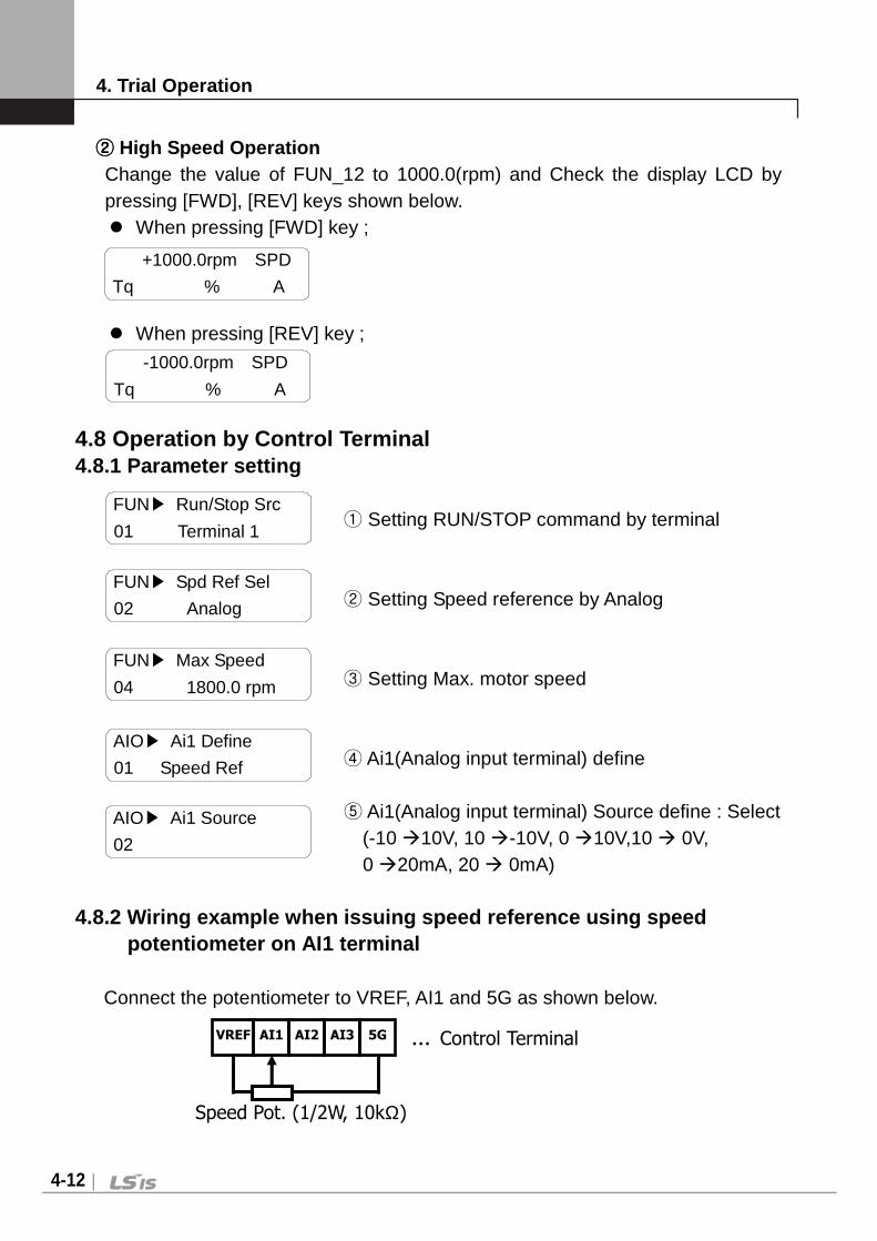
②②②② High Speed Operation Change the value of FUN_12 to 1000.0(rpm) and Check the display LCD by pressing [FWD], [REV] keys shown below. When pressing [FWD] key ;
When pressing [REV] key ; 4.8 Operation by Control Terminal 4.8.1 Parameter setting ① Setting RUN/STOP command by terminal ② Setting Speed reference by Analog ③ Setting Max. motor speed ④ Ai1(Analog input terminal) define
⑤ Ai1(Analog input terminal) Source define : Select (-10 10V, 10 -10V, 0 10V,10 0V,
0 20mA, 20 0mA)
4.8.2 Wiring example when issuing speed reference u sing speed potentiometer on AI1 terminal
Connect the potentiometer to VREF, AI1 and 5G as shown below.
+1000.0rpm SPD
Tq % A
-1000.0rpm SPD
Tq % A
FUN Run/Stop Src
01 Terminal 1
FUN Spd Ref Sel
02 Analog
FUN Max Speed
04 1800.0 rpm
AIO Ai1 Define
01 Speed Ref
AIO Ai1 Source
02
VREF AI1 AI2 AI3 … Control Terminal 5G
Speed Pot. (1/2W, 10kΩ)

4. Trial Operation
4-13
4.8.3 Adjusting Ai1 Gain and Bias (example of analo g input Ai1 setting) ①①①① Out Y2(Gain) Adjustment of Analog input
Apply 10V or 20mA between AI1 ~ 5G (for setting by potentiometer, adjust it to Max).
Adjust the other multi analog input terminals in same manner.
Key Handling
Loader Display Description
Initial LCD display
PROG Pressing [PROG] key, shows in upper side the percent of input to output and in low side the gain value be set presently.
If you try to adjust the gain to show 100.00%, Press [(Up)] key repeatedly and set to be 102.00%.
ENT After adjusting Gain, if you enter [ENT] key, the adjusted gain value is saved.
②②②② Out Y1(Bias) Adjustment of Analog input Apply 0V or 0mA between AI1 ~ 5G
(for setting by potentiometer, adjust it to Min). Adjust the other multi analog input terminals in same manner.
Key Handling
Loader Display Description
Initial LCD display
PROG
Pressing [PROG] key, shows in upper side the percent of input to output and in low side the Bias value be set presently.
If you try to adjust the Bias to show 0.00%, Press [(Up)] key repeatedly and set to be 0.00%.
ENT After adjusting Bias, if you enter [ENT] key, the adjusted Bias value is saved.
AIO Ai1 Out Y2 06 100.00 %
AIOAi1 98.00 % 06 Gain 100.00 %
AIOAi1 100.00 % 06 Gain 102.00 %
AIO Ai1 Out Y2 06 102.00 %
AIO Ai1 Out Y1 04 0.00 %
AIOAi1 0.18 % 04 Bias 0.00 %
AIOAi1 0.00 % 04 Bias 0.18 %
AIO Ai1 Out Y1 04 0.18 %
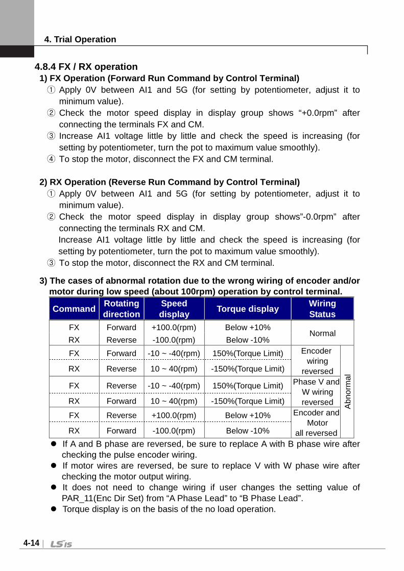
4. Trial Operation
4-14
4.8.4 FX / RX operation 1) FX Operation (Forward Run Command by Control Ter minal) ① Apply 0V between AI1 and 5G (for setting by potentiometer, adjust it to
minimum value). ② Check the motor speed display in display group shows “+0.0rpm” after
connecting the terminals FX and CM. ③ Increase AI1 voltage little by little and check the speed is increasing (for
setting by potentiometer, turn the pot to maximum value smoothly). ④ To stop the motor, disconnect the FX and CM terminal.
2) RX Operation (Reverse Run Command by Control Ter minal) ① Apply 0V between AI1 and 5G (for setting by potentiometer, adjust it to
minimum value). ② Check the motor speed display in display group shows”-0.0rpm” after
connecting the terminals RX and CM. Increase AI1 voltage little by little and check the speed is increasing (for setting by potentiometer, turn the pot to maximum value smoothly).
③ To stop the motor, disconnect the RX and CM terminal.
3) The cases of abnormal rotation due to the wrong wiring of encoder and/or motor during low speed (about 100rpm) operation by control terminal.
Command Rotating direction
Speed display
Torque display Wiring Status
FX Forward +100.0(rpm) Below +10% Normal
RX Reverse -100.0(rpm) Below -10%
FX Forward -10 ~ -40(rpm) 150%(Torque Limit) Encoder wiring
reversed
Abn
orm
al RX Reverse 10 ~ 40(rpm) -150%(Torque Limit)
FX Reverse -10 ~ -40(rpm) 150%(Torque Limit) Phase V and W wiring reversed RX Forward 10 ~ 40(rpm) -150%(Torque Limit)
FX Reverse +100.0(rpm) Below +10% Encoder and Motor
all reversed RX Forward -100.0(rpm) Below -10%
If A and B phase are reversed, be sure to replace A with B phase wire after checking the pulse encoder wiring.
If motor wires are reversed, be sure to replace V with W phase wire after checking the motor output wiring.
It does not need to change wiring if user changes the setting value of PAR_11(Enc Dir Set) from “A Phase Lead” to “B Phase Lead”.
Torque display is on the basis of the no load operation.

4. Trial Operation
4-15
Operation Example (1)
Speed Setting via Keypad + Run/Stop via Terminal (F X/RX)
[Operation condition] -. Control mode : Speed control -. Ref. Speed : 1500[rpm] setting via keypad -. Accel/Decel time : Accel - 10[sec], Decel - 20[sec] -. Run/Stop Src : Run/Stop via FX/RX terminal, Control terminal: NPN mode
[Wiring] RRRR
SSSS
TTTT
GGGG
UUUU
VVVV
WWWW
FXFXFXFXRXRXRXRX
BXBXBXBX
RSTRSTRSTRST
PPPP1111PPPP2222
PPPP3333PPPP4444
CMCMCMCM
VREFVREFVREFVREF
AIAIAIAI1111
5555GGGG
PEPEPEPE
30303030AAAA
30303030CCCC
30303030BBBB
1111AAAA
1111BBBB
IMIMIMIM3333PPPPACACACAC
INPUTINPUTINPUTINPUT
SSSS////WWWWEEEE
GEGEGEGE
EncoderEncoderEncoderEncoder
AAAA++++AAAA----BBBB++++BBBB----
2222AAAA
2222BBBB
OCOCOCOC1111
EGEGEGEG
PPPP5555PPPP6666
PPPP7777
AIAIAIAI2222
AIAIAIAI3333
Step Parameter
setting Code Description
1 RUN/STOP
source select FUN_01 Set it to 0 “Terminal 1”.
2 Speed setting
method FUN_02 Set it to 1 “Keypad1”.
3 Ref. Speed
setting FUN_12 Set speed command 1500[rpm] via Keypad.
4 Accel/Decel
time FUN_40 FUN_41
Set Accel time to 10 [sec] in FUN_40. Set Decel time to 20 [sec] in FUN_41.
5 Terminal FX -
Motor starts to rotate in Forward direction at 1500[rpm] with Accel time 10 [sec] when FX terminal is turned ON. Motor decelerates to stop with Decel time 20[sec] when FX terminal is turned OFF.
6 Terminal RX -
When RX terminal is turned ON motor starts to rotate in Reverse direction at 1500[rpm] with Accel time 10 [sec]. When it is OFF, motor decelerates to stop with Decel time 20 [sec].

4. Trial Operation
4-16
Operation Example (2)
Analog Voltage Input(AI1) + Run/Stop via Terminal (FX/RX)
[Operation condition] -. Control mode : Speed control -. Ref. Speed : 1500[rpm] analog input via AI1 (Potentiometer) -. Accel/Decel time : Accel - 10[sec], Decel - 20[sec] -. Run/Stop Src : Run/Stop via FX/RX terminal, Control terminal: NPN mode
[Wiring] RRRR
SSSS
TTTT
GGGG
UUUU
VVVV
WWWW
FXFXFXFXRXRXRXRX
BXBXBXBX
RSTRSTRSTRST
PPPP1111PPPP2222PPPP3333
PPPP4444
CMCMCMCM
VREFVREFVREFVREF
AIAIAIAI1111
5555GGGG
PEPEPEPE
30303030AAAA
30303030CCCC
30303030BBBB
1111AAAA
1111BBBB
IMIMIMIM3333PPPPACACACAC
INPUTINPUTINPUTINPUT
PotentiometerPotentiometerPotentiometerPotentiometer10101010kkkkΩ1111////2222WWWW
SSSS////WWWWEEEE
GEGEGEGE
EncoderEncoderEncoderEncoder
AAAA++++AAAA----BBBB++++BBBB----
2222AAAA
2222BBBB
OCOCOCOC1111
EGEGEGEG
PPPP5555PPPP6666
PPPP7777
AIAIAIAI2222
AIAIAIAI3333
Step Parameter setting Code Description
1 RUN/STOP
source select FUN_01 Set it to 0 “Terminal 1”.
2 Speed setting
method FUN_02 Set it to 0 “Analog”.
3 Analog Input 1
definition AIO_01 Set it to 1 “Speed Ref”.
4 Analog Input 1 Input Method
definition AIO_02 Set it to 2 “0 → 10V”.
5 Ref. Speed
setting DIS_01
Set speed command 1500[rpm] via AI1(Potentionmeter) in DIS_01 PreRamp Ref.
6 Accel/Decel
time FUN_40 FUN_41
Set Accel time to 10 [sec] in FUN_40. Set D cel time to 20 [sec] in FUN_41.
7 Terminal FX -
Motor starts to rotate in Forward direction at 1500[rpm] with Accel time 10 [sec] when FX terminal is turned ON. Motor decelerates to stop with Decel time 20[sec] when FX terminal is turned OFF.
8 Terminal RX -
When RX terminal is turned ON motor starts to rotate in Reverse direction at 1500[rpm] with Accel time 10 [sec]. When it is OFF, motor decelerates to stop with Decel time 20 [sec].

4. Trial Operation
4-17

5. Function Code Table
5-1
Chapter 5 - Function Code Table * The number of page is for User’s manual uploaded at LSIS website. You can download the User’s manual which is described detailed function of parameter from website. (http://www.lsis.com)
5.1. Display Group (DIS_[][])
* ‘ – ‘ mark of communication adrress indicates communication exclusion.
* Setting during Inverter operation (Yes : possible, No : impossible)
CODE No.
Comm. Addr.
CODE NAME LCD DISPLAY SETTING DATA Adjustment
During Run 1) RANGE UNIT DEFAULT
DIS_00 - Motor Speed/Control Mode
OutputTorque/Output Current 0.0 rpm SPD Tq 0.0% 0.0A
- -
DIS_01 - User Display 1
Ai1 Value %
PreRamp Ref
Yes
Ai2 Value %
Ai3 Value %
Ai4 Value1) %
Ai5 Value 1) %
PreRamp Ref rpm
PostRamp Ref rpm
ASR Inp Ref rpm
Motor Speed rpm
Motor SpdEst rpm
Speed Dev rpm
ASR Out %
Torque Bias %
PosTrq Limit %
NegTrq Limit - %
RegTrq Limit %
Torque Ref %
IqeRef A
Iqe A
Flux Ref %
Ide Ref A
Ide A
ACR_Q Out V
ACR_D Out V
VdeRef V
VqeRef V
Out Amps RMS A
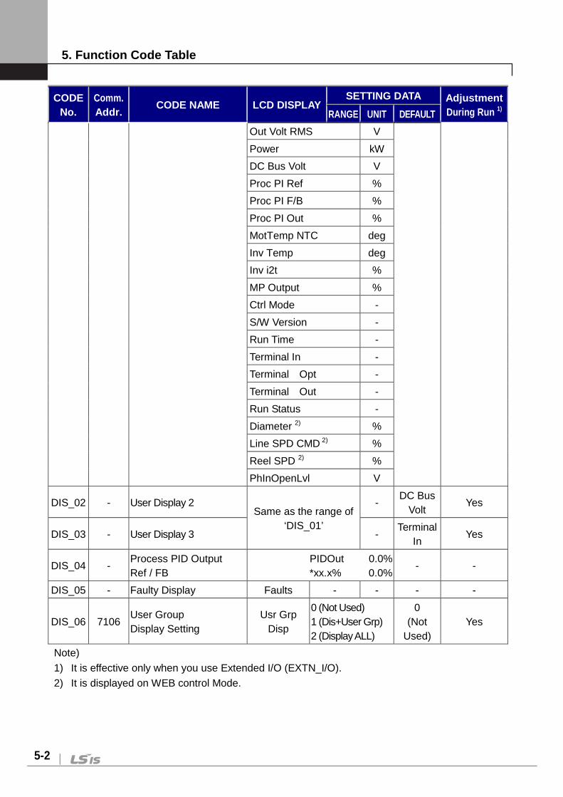
5. Function Code Table
5-2
CODE No.
Comm. Addr.
CODE NAME LCD DISPLAY SETTING DATA Adjustment
During Run 1) RANGE UNIT DEFAULT
Out Volt RMS V
Power kW
DC Bus Volt V
Proc PI Ref %
Proc PI F/B %
Proc PI Out %
MotTemp NTC deg
Inv Temp deg
Inv i2t %
MP Output %
Ctrl Mode -
S/W Version -
Run Time -
Terminal In -
Terminal Opt -
Terminal Out -
Run Status -
Diameter 2) %
Line SPD CMD 2) %
Reel SPD 2) %
PhInOpenLvl V
DIS_02 - User Display 2 Same as the range of
‘DIS_01’
- DC Bus
Volt Yes
DIS_03 - User Display 3 - Terminal
In Yes
DIS_04 - Process PID Output Ref / FB
PIDOut 0.0% *xx.x% 0.0%
- -
DIS_05 - Faulty Display Faults - - - -
DIS_06 7106 User Group Display Setting
Usr Grp Disp
0 (Not Used) 1 (Dis+User Grp) 2 (Display ALL)
0 (Not
Used) Yes
Note)
1) It is effective only when you use Extended I/O (EXTN_I/O).
2) It is displayed on WEB control Mode.
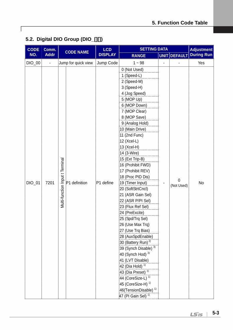
5. Function Code Table
5-3
5.2. Digital DIO Group (DIO_[][])
CODE NO.
Comm. Addr CODE NAME LCD
DISPLAY SETTING DATA Adjustment
During Run RANGE UNIT DEFAULT
DIO_00 - Jump for quick view Jump Code 1 ~ 98 - - Yes
DIO_01 7201
Mul
ti-fu
nctio
n In
put t
Ter
min
al
P1 definition P1 define
0 (Not Used)
- 0
(Not Used) No
1 (Speed-L) 2 (Speed-M) 3 (Speed-H) 4 (Jog Speed) 5 (MOP Up) 6 (MOP Down) 7 (MOP Clear) 8 (MOP Save) 9 (Analog Hold) 10 (Main Drive) 11 (2nd Func) 12 (Xcel-L) 13 (Xcel-H) 14 (3-Wire) 15 (Ext Trip-B) 16 (Prohibit FWD) 17 (Prohibit REV) 18 (Proc PID Dis) 19 (Timer Input) 20 (SoftStrtCncl) 21 (ASR Gain Sel) 22 (ASR P/PI Sel) 23 (Flux Ref Sel) 24 (PreExcite) 25 (Spd/Trq Sel) 26 (Use Max Trq) 27 (Use Trq Bias) 28 (AuxSpdEnable) 30 (Battery Run) 2) 39 (Synch Disable) 3) 40 (Synch Hod) 3) 41 (LVT Disable) 42 (Dia Hold) 1) 43 (Dia Preset) 1) 44 (CoreSize-L) 1) 45 (CoreSize-H) 1) 46(TensionDisable) 1) 47 (PI Gain Sel) 1)

5. Function Code Table
5-4
CODE NO.
Comm. Addr CODE NAME
LCD DISPLAY
SETTING DATA Adjustment During Run RANGE UNIT DEFAULT
48 (PID ITerm Clr) 1) 49 (Taper Disable) 1) 50 (Stall Enable) 1) 51 (Boost Enable) 1) 52 (Quick Stop) 1) 53 (Jog Web Fwd) 1) 54 (Jog Web Rev) 1) 55 (Under Wind) 1) 56 (Unwinder) 1)
DIO_02 7202
Mul
ti-fu
nctio
n In
put T
erm
inal
P2 definition P2 define
Same as the range of ‘DIO_1’
- 0
(Not Used) No
DIO_03 7203 P3 definition P3 define - 0
(Not Used) No
DIO_04 7204 P4 definition P4 define - 0
(Not Used) No
DIO_05 7205 P5 definition P5 define - 0
(Not Used) No
DIO_06 7206 P6 definition P6 define - 0
(Not Used) No
DIO_07 7207 P7 definition P7 define - 0
(Not Used) No
DIO_08 - Negative function of multi-function input terminal
Neg Func. In
0000000~ 1111111 bit 0000000 No
DIO_09 7209 Multi-function Input LPF time constant
Terminal LPF
0 ~ 2000 - 5 Yes
DIO_10 -
Negative function of multi-function auxiliary output terminal
Neg Func. Out
00000~ 11111 bit 00000 No
DIO_41 7229
Mul
ti-fu
nctio
n A
uxili
ary
outp
ut
Definition of AX1 AX1 Define
0 (Not Used)
- 0
(Not Used) Yes
1 (INV Ready)
2 (Zero Spd Det)
3 (Spd Det.)
4 (Spd Det(ABS))
5 (Spd Arrival)
6 (Timer Out)
7 (LV Warn)
8 (Run)
9 (Regenerating)
10 (Mot OH Warn)
11 (Inv OH Warn)
12 (Spd Agree)
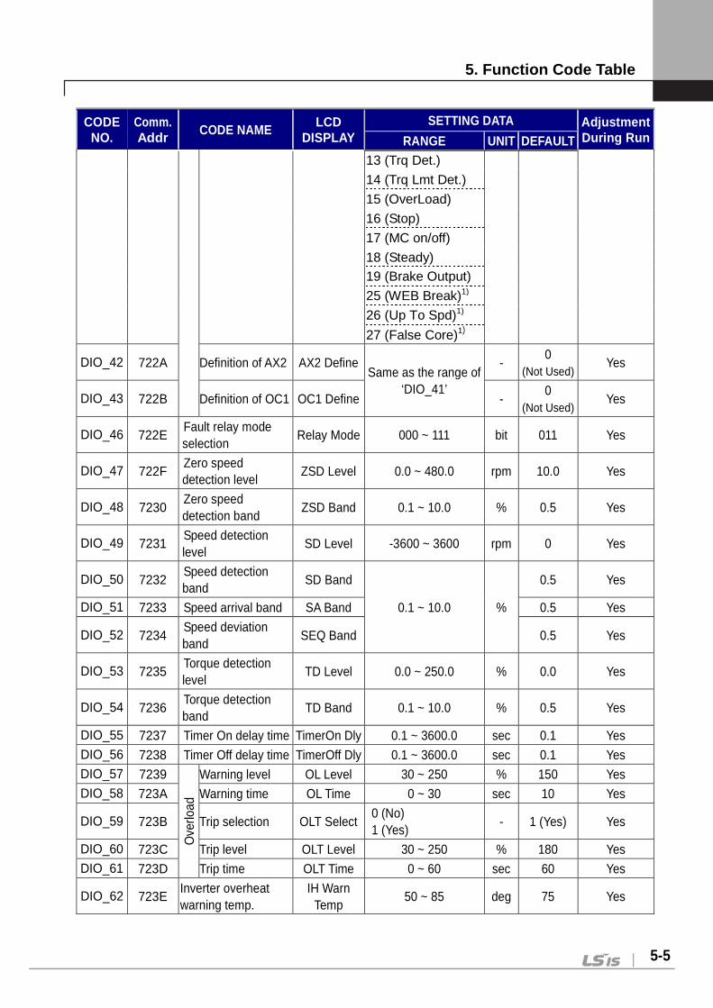
5. Function Code Table
5-5
CODE NO.
Comm. Addr CODE NAME
LCD DISPLAY
SETTING DATA Adjustment During Run RANGE UNIT DEFAULT
13 (Trq Det.)
14 (Trq Lmt Det.)
15 (OverLoad)
16 (Stop)
17 (MC on/off)
18 (Steady) 19 (Brake Output)
25 (WEB Break)1)
26 (Up To Spd)1)
27 (False Core)1)
DIO_42 722A Definition of AX2 AX2 Define Same as the range of
‘DIO_41’
- 0
(Not Used) Yes
DIO_43 722B Definition of OC1 OC1 Define - 0
(Not Used) Yes
DIO_46 722E Fault relay mode selection
Relay Mode 000 ~ 111 bit 011 Yes
DIO_47 722F Zero speed detection level
ZSD Level 0.0 ~ 480.0 rpm 10.0 Yes
DIO_48 7230 Zero speed detection band
ZSD Band 0.1 ~ 10.0 % 0.5 Yes
DIO_49 7231 Speed detection level
SD Level -3600 ~ 3600 rpm 0 Yes
DIO_50 7232 Speed detection band
SD Band
0.1 ~ 10.0 %
0.5 Yes
DIO_51 7233 Speed arrival band SA Band 0.5 Yes
DIO_52 7234 Speed deviation band
SEQ Band 0.5 Yes
DIO_53 7235 Torque detection level
TD Level 0.0 ~ 250.0 % 0.0 Yes
DIO_54 7236 Torque detection band
TD Band 0.1 ~ 10.0 % 0.5 Yes
DIO_55 7237 Timer On delay time TimerOn Dly 0.1 ~ 3600.0 sec 0.1 Yes DIO_56 7238 Timer Off delay time TimerOff Dly 0.1 ~ 3600.0 sec 0.1 Yes DIO_57 7239
Ove
rload
Warning level OL Level 30 ~ 250 % 150 Yes DIO_58 723A Warning time OL Time 0 ~ 30 sec 10 Yes
DIO_59 723B Trip selection OLT Select 0 (No) 1 (Yes)
- 1 (Yes) Yes
DIO_60 723C Trip level OLT Level 30 ~ 250 % 180 Yes DIO_61 723D Trip time OLT Time 0 ~ 60 sec 60 Yes
DIO_62 723E Inverter overheat warning temp.
IH Warn Temp
50 ~ 85 deg 75 Yes

5. Function Code Table
5-6
CODE NO.
Comm. Addr CODE NAME
LCD DISPLAY
SETTING DATA Adjustment During Run RANGE UNIT DEFAULT
DIO_63 723F Inverter overheat warning band
IH Warn Band
0 ~ 10 deg 5 Yes
DIO_64 7240 Motor overheat warning temp.
MH Warn Temp
75 ~ 130 deg 120 Yes
DIO_65 7241 Motor overheat warning band
MH Warn Band
0 ~ 10 deg 5 Yes
DIO_67 7243 MC ON delay time 4)
MC Timer Off
100~50000 msec 1000 No
DIO_68 7244 MC OFF delay time 4)
MC Timer Off
100~50000 msec 1000 No
DIO_95 725F Inverter station address
Inv Number
1~250 1 No
DIO_96 7260 485 BaudRate 485
BaudRate
0 (1200)
bps 9600 No
1 (2400)
2 (4800)
3 (9600)
4 (19200)
5 (384000)
DIO_97 7261 How to Run at Lost command
Lost Command
0 (None)
- 0
(None) No 1 (FreeRun)
2 (Stop)
DIO_98 7262
Decision time when communication command is lost. 4)
Comm. Timer
10~300 sec 10 No
Note)
1) Displayed WEB Control mode setting.
2) It can be set at 5.5 ~ 22 kW-2/4 class.
3) It will be displayed as CON_02 sets to ‘Synchro’ when Synchronization option board is
installed.
4) It will be displayed when the definition of multi-funtion output sets as ‘MC On/Off’.
5) It will be displayed RS-485 communication option board is installed. Refer to the user manual
for RS485/Modbus-RTU option board (iP5A/iV5).
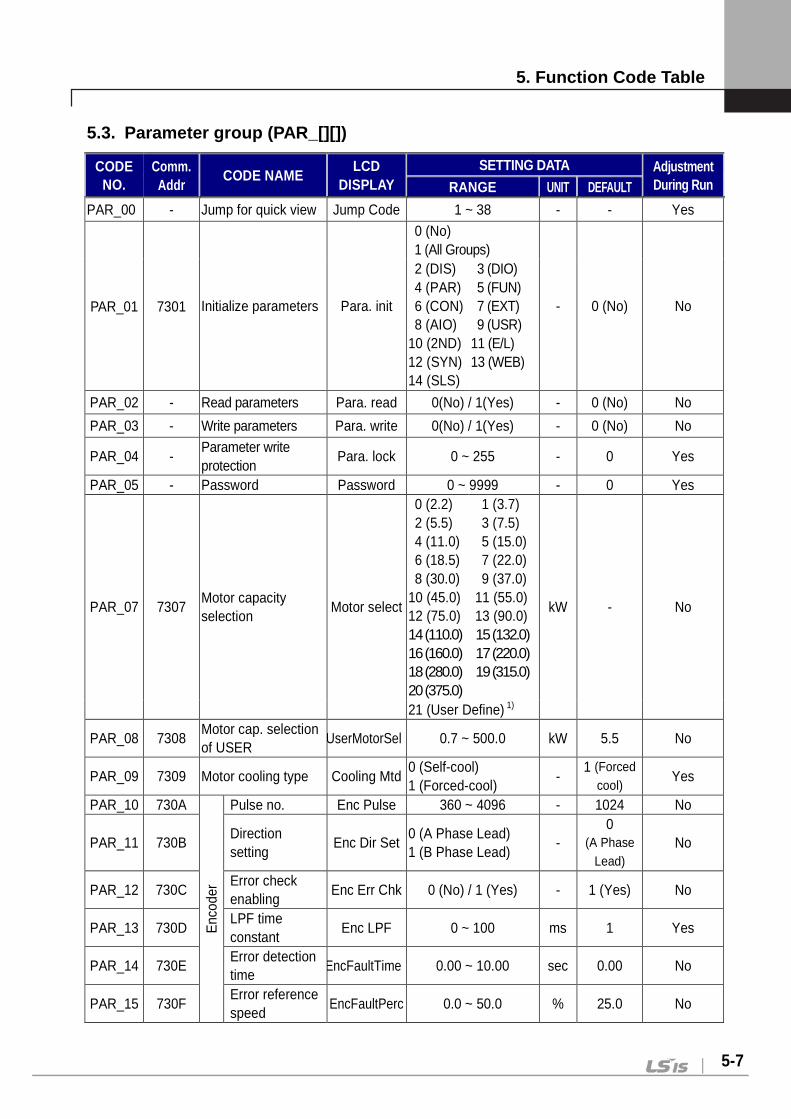
5. Function Code Table
5-7
5.3. Parameter group (PAR_[][])
CODE NO.
Comm. Addr
CODE NAME LCD
DISPLAY SETTING DATA Adjustment
During Run RANGE UNIT DEFAULT
PAR_00 - Jump for quick view Jump Code 1 ~ 38 - - Yes
PAR_01 7301 Initialize parameters Para. init
0 (No) 1 (All Groups)
- 0 (No) No
2 (DIS) 4 (PAR) 6 (CON) 8 (AIO)
10 (2ND) 12 (SYN) 14 (SLS)
3 (DIO) 5 (FUN) 7 (EXT) 9 (USR)
11 (E/L) 13 (WEB)
PAR_02 - Read parameters Para. read 0(No) / 1(Yes) - 0 (No) No
PAR_03 - Write parameters Para. write 0(No) / 1(Yes) - 0 (No) No
PAR_04 - Parameter write protection
Para. lock 0 ~ 255 - 0 Yes
PAR_05 - Password Password 0 ~ 9999 - 0 Yes
PAR_07 7307 Motor capacity selection
Motor select
0 (2.2) 2 (5.5) 4 (11.0) 6 (18.5) 8 (30.0)
10 (45.0) 12 (75.0) 14 (110.0) 16 (160.0) 18 (280.0) 20 (375.0)
1 (3.7) 3 (7.5) 5 (15.0) 7 (22.0) 9 (37.0)
11 (55.0) 13 (90.0) 15 (132.0) 17 (220.0) 19 (315.0)
kW - No
21 (User Define) 1)
PAR_08 7308 Motor cap. selection of USER
UserMotorSel 0.7 ~ 500.0 kW 5.5 No
PAR_09 7309 Motor cooling type Cooling Mtd 0 (Self-cool) 1 (Forced-cool)
- 1 (Forced
cool) Yes
PAR_10 730A
Enc
oder
Pulse no. Enc Pulse 360 ~ 4096 - 1024 No
PAR_11 730B Direction setting
Enc Dir Set 0 (A Phase Lead) 1 (B Phase Lead)
- 0
(A Phase Lead)
No
PAR_12 730C Error check enabling
Enc Err Chk 0 (No) / 1 (Yes) - 1 (Yes) No
PAR_13 730D LPF time constant
Enc LPF 0 ~ 100 ms 1 Yes
PAR_14 730E Error detection time
EncFaultTime 0.00 ~ 10.00 sec 0.00 No
PAR_15 730F Error reference speed
EncFaultPerc 0.0 ~ 50.0 % 25.0 No
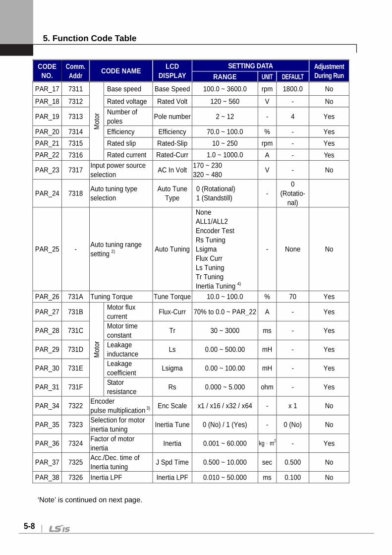
5. Function Code Table
5-8
CODE NO.
Comm. Addr
CODE NAME LCD
DISPLAY SETTING DATA Adjustment
During Run RANGE UNIT DEFAULT
PAR_17 7311 M
otor
Base speed Base Speed 100.0 ~ 3600.0 rpm 1800.0 No
PAR_18 7312 Rated voltage Rated Volt 120 ~ 560 V - No
PAR_19 7313 Number of poles
Pole number 2 ~ 12 - 4 Yes
PAR_20 7314 Efficiency Efficiency 70.0 ~ 100.0 % - Yes
PAR_21 7315 Rated slip Rated-Slip 10 ~ 250 rpm - Yes
PAR_22 7316 Rated current Rated-Curr 1.0 ~ 1000.0 A - Yes
PAR_23 7317 Input power source selection
AC In Volt 170 ~ 230 320 ~ 480
V - No
PAR_24 7318 Auto tuning type selection
Auto Tune Type
0 (Rotational) 1 (Standstill)
- 0
(Rotatio- nal)
PAR_25 - Auto tuning range setting 2)
Auto Tuning
None ALL1/ALL2 Encoder Test Rs Tuning Lsigma Flux Curr Ls Tuning Tr Tuning Inertia Tuning 4)
- None No
PAR_26 731A Tuning Torque Tune Torque 10.0 ~ 100.0 % 70 Yes
PAR_27 731B
Mot
or
Motor flux current
Flux-Curr 70% to 0.0 ~ PAR_22 A - Yes
PAR_28 731C Motor time constant
Tr 30 ~ 3000 ms - Yes
PAR_29 731D Leakage inductance
Ls 0.00 ~ 500.00 mH - Yes
PAR_30 731E Leakage coefficient
Lsigma 0.00 ~ 100.00 mH - Yes
PAR_31 731F Stator resistance
Rs 0.000 ~ 5.000 ohm - Yes
PAR_34 7322 Encoder pulse multiplication 3)
Enc Scale x1 / x16 / x32 / x64 - x 1 No
PAR_35 7323 Selection for motor inertia tuning
Inertia Tune 0 (No) / 1 (Yes) - 0 (No) No
PAR_36 7324 Factor of motor inertia
Inertia 0.001 ~ 60.000 kg·m2 - Yes
PAR_37 7325 Acc./Dec. time of Inertia tuning
J Spd Time 0.500 ~ 10.000 sec 0.500 No
PAR_38 7326 Inertia LPF Inertia LPF 0.010 ~ 50.000 ms 0.100 No
‘Note’ is continued on next page.
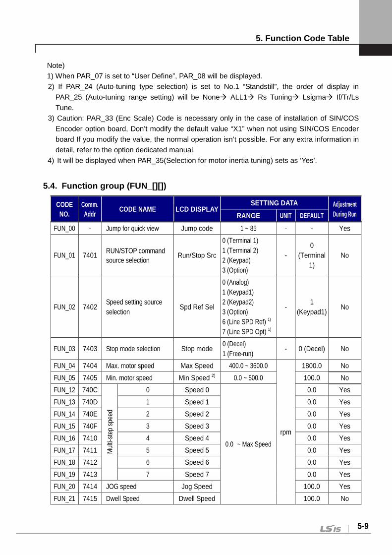
5. Function Code Table
5-9
Note)
1) When PAR_07 is set to “User Define”, PAR_08 will be displayed.
2) If PAR_24 (Auto-tuning type selection) is set to No.1 “Standstill”, the order of display in
PAR_25 (Auto-tuning range setting) will be None ALL1 Rs Tuning Lsigma If/Tr/Ls
Tune.
3) Caution: PAR_33 (Enc Scale) Code is necessary only in the case of installation of SIN/COS
Encoder option board, Don’t modify the default value “X1” when not using SIN/COS Encoder
board If you modify the value, the normal operation isn’t possible. For any extra information in
detail, refer to the option dedicated manual.
4) It will be displayed when PAR_35(Selection for motor inertia tuning) sets as ‘Yes’.
5.4. Function group (FUN_[][])
CODE NO.
Comm. Addr
CODE NAME LCD DISPLAY SETTING DATA Adjustment
During Run RANGE UNIT DEFAULT
FUN_00 - Jump for quick view Jump code 1 ~ 85 - - Yes
FUN_01 7401 RUN/STOP command source selection
Run/Stop Src
0 (Terminal 1) 1 (Terminal 2) 2 (Keypad) 3 (Option)
- 0
(Terminal 1)
No
FUN_02 7402 Speed setting source selection
Spd Ref Sel
0 (Analog) 1 (Keypad1) 2 (Keypad2) 3 (Option) 6 (Line SPD Ref) 1) 7 (Line SPD Opt) 1)
- 1
(Keypad1) No
FUN_03 7403 Stop mode selection Stop mode 0 (Decel) 1 (Free-run)
- 0 (Decel) No
FUN_04 7404 Max. motor speed Max Speed 400.0 ~ 3600.0
rpm
1800.0 No
FUN_05 7405 Min. motor speed Min Speed 2) 0.0 ~ 500.0 100.0 No
FUN_12 740C
Mul
ti-st
ep s
peed
0 Speed 0
0.0 ~ Max Speed
0.0 Yes
FUN_13 740D 1 Speed 1 0.0 Yes
FUN_14 740E 2 Speed 2 0.0 Yes
FUN_15 740F 3 Speed 3 0.0 Yes
FUN_16 7410 4 Speed 4 0.0 Yes
FUN_17 7411 5 Speed 5 0.0 Yes
FUN_18 7412 6 Speed 6 0.0 Yes
FUN_19 7413 7 Speed 7 0.0 Yes
FUN_20 7414 JOG speed Jog Speed 100.0 Yes
FUN_21 7415 Dwell Speed Dwell Speed 100.0 No
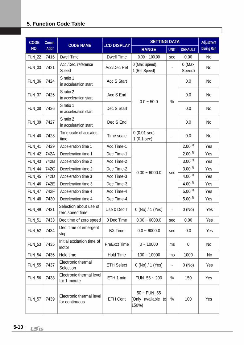
5. Function Code Table
5-10
CODE NO.
Comm. Addr
CODE NAME LCD DISPLAY SETTING DATA Adjustment
During Run RANGE UNIT DEFAULT
FUN_22 7416 Dwell Time Dwell Time 0.00 ~ 100.00 sec 0.00 No
FUN_33 7421 Acc./Dec. reference Speed
Acc/Dec Ref 0 (Max Speed) 1 (Ref Speed)
- 0 (Max Speed)
No
FUN_36 7424 S ratio 1 in acceleration start
Acc S Start
0.0 ~ 50.0 %
0.0 No
FUN_37 7425 S ratio 2 in acceleration start
Acc S End 0.0 No
FUN_38 7426 S ratio 1 in acceleration start
Dec S Start 0.0 No
FUN_39 7427 S ratio 2 in acceleration start
Dec S End 0.0 No
FUN_40 7428 Time scale of acc./dec. time
Time scale 0 (0.01 sec) 1 (0.1 sec)
- 0.0 No
FUN_41 7429 Acceleration time 1 Acc Time-1
0.00 ~ 6000.0 sec
2.00 2) Yes
FUN_42 742A Deceleration time 1 Dec Time-1 2.00 2) Yes
FUN_43 742B Acceleration time 2 Acc Time-2 3.00 2) Yes
FUN_44 742C Deceleration time 2 Dec Time-2 3.00 2) Yes
FUN_45 742D Acceleration time 3 Acc Time-3 4.00 2) Yes
FUN_46 742E Deceleration time 3 Dec Time-3 4.00 2) Yes
FUN_47 742F Acceleration time 4 Acc Time-4 5.00 2) Yes
FUN_48 7430 Deceleration time 4 Dec Time-4 5.00 2) Yes
FUN_49 7431 Selection about use of zero speed time
Use 0 Dec T 0 (No) / 1 (Yes) - 0 (No) Yes
FUN_51 7433 Dec.time of zero speed 0 Dec Time 0.00 ~ 6000.0 sec 0.00 Yes
FUN_52 7434 Dec. time of emergent stop
BX Time 0.0 ~ 6000.0 sec 0.0 Yes
FUN_53 7435 Initial excitation time of motor
PreExct Time 0 ~ 10000 ms 0 No
FUN_54 7436 Hold time Hold Time 100 ~ 10000 ms 1000 No
FUN_55 7437 Electronic thermal Selection
ETH Select 0 (No) / 1 (Yes) - 0 (No) Yes
FUN_56 7438 Electronic thermal level for 1 minute
ETH 1 min FUN_56 ~ 200 % 150 Yes
FUN_57 7439 Electronic thermal level for continuous
ETH Cont 50 ~ FUN_55
(Only available to 150%)
% 100 Yes

5. Function Code Table
5-11
CODE NO.
Comm. Addr
CODE NAME LCD DISPLAY SETTING DATA Adjustment
During Run RANGE UNIT DEFAULT
FUN_58 743A Switching frequency select
PWM Freq 2.5 ~ 10.0 4) kHz According to inverter capacity
No
FUN_59 743B Power on Run selection Power-on Run 0 (No) / 1 (Yes) - 0 (No) Yes
FUN_60 743C Restart after fault reset RST Restart 0 (No) / 1 (Yes) - 0 (No) Yes
FUN_61 743D Number of auto restart try
Retry Number 0 ~ 10 - 0 Yes
FUN_62 743E Delay time before Auto restart
Retry Delay 0.0 ~ 60.0 sec 1.0 Yes
FUN_63 743F Wait time for Restart upon Stop
Restart Time5) 0.00 ~ 10.00 sec 0.00 No
FUN_64 7440 Overspeed Detection Time
OverSpdLevel 100.0 ~ 130.0 % 120.0 No
FUN_65 7441 Electronic thermal level for 1 minute
OverSpd Time 0.00 ~ 2.00 sec 0.00 No
FUN_66 7442
Bra
ke
Open Time 6) BKOpen Time 0.00 ~ 30.00 sec 0.00 No
FUN_67 7443 Open Speed 6) BKOpen Spd 0.0 ~ 500.0 rpm 0.0 No
FUN_68 7444 Open Current 6) Release Curr 0.0 ~ 150.0 % 20.0 No
FUN_69 7445 Close Time 6) BKClose Time 0.00 ~ 30.00 sec 0.00 No
FUN_70 7446 Close Speed 6) BKClose Spd 0.0 ~ 500.0 rpm 0.0 No
FUN_71 7447
Reg
erne
ratio
n pr
even
tion
Run selection RegenAvd Sel 0 (No) / 1 (Yes) - 0 (No) No
FUN_72 7448 Run voltage level 7)
RegenAvd Lvl 600(300) ~ 800(400)
V 700(350) No
FUN_73 7449 Speed limitation 7) CompFreq Lmt 0.0 ~ 500.0 rpm 100.0 No
FUN_74 744A Speed P gain 7) RegenAvd P 0.0 ~ 300.0 % 50.0 Yes
FUN_75 744B Speed I gain 7) RegenAvd I 20 ~ 30000 ms 500 Yes
FUN_76 744C Speed in battery-operated mode 8)
Batt. Speed 2.5 ~ 200.0 rpm 50.0 No
FUN_77 744D Battery input voltage 8) Batt. Volt 12 ~ PAR_18 V 48 No
FUN_78 744E Check of input phase-open
PhInOpenChk 0 (No) / 1 (Yes) - 1 (Yes) No
FUN_79 7450 Check level of input phase-open
PhInOpenLvl 2.0 ~ 100.0 V 3.0 Yes
FUN_80 7451 Check of output phase-open
PhOutOpenChk 0 (No) / 1 (Yes) - 1 (Yes) No
FUN_81 7452 Max. auxiliary speed AuxSpeedMax 0.0~500.0 rpm 10.0 Yes

5. Function Code Table
5-12
CODE NO.
Comm. Addr
CODE NAME LCD DISPLAY SETTING DATA Adjustment
During Run RANGE UNIT DEFAULT
FUN_82 7453 Calculation method of
auxiliary speed AuxSpeedType 0 ~ 1 - 0 No
FUN_83 7454 Acc. time of auxiliary
speed AuxAccTime 0.00 ~ 600.00 sec 2.00 No
FUN_84 7455 Dec. time of auxiliary
speed AuxDecTime 0.00 ~ 600.00 sec 2.00 No
FUN_85 7456 Absolute/Relative mode
for auxiliary speed AuxSpeedMode
0(Absolute) /1(Relative)
- 0
(Absolute) No
FUN_86 7457 Speed in short floor
operation mode ShortFlr Spd 0.0~Max Speed rpm 0.0 No
FUN_87 7458 Time of short floor operation mode
ShortFlrTime 0.00~100.00 sec 0.00 No
FUN_88 7459 Low Voltage2 Selection LV2 Enable 0 (No) / 1 (Yes) - 0 (No) Yes
Note)
1) It will be displayed when WEB control mode is set.
2) It will be displayed when CON_01 is set to Sensorless.
3) A default value of a time of acceleration and deceleration is different from the setting capacity
of inverter.
4) Minimum/Maximum values are different from the capacity of inverter.
5) It will be displayed when FUN_03 (Stop method) is set to ‘Free-run’.
6) It will be displayed when the definition of DIO_41 to DIO_43 (Auxiliary output terminal of
multi-funtion) is set to ‘Brake Output’.
7) It will be displayed when FUN_71 is set to ‘Yes’.
8) It can set for only 5.5 ~ 22 kW/2/4 products in case ‘Battery Run’ of multi-function input
terminal (P1 ~ P&) is turned On.

5. Function Code Table
5-13
5.5. Control group (CON_[][])
CODE NO.
Comm. Addr.
CODE NAME LCD DISPLAY SETTING DATA Adjustment
During Run RANGE UNIT DEFAULT
CON_00 - Jump for quick view Jump Code 1 ~ 80 - - Yes
CON_01 7501 Control mode setting Control Mode 1 (Speed) 2 (Torque) 3 (Sensorless)
- 1 (Speed) No
CON_02 - Application mode setting
Application
General Vect Elevator 1)
Synchro 2) WEB Control
- General
Vect No
CON_03 7503
AS
R
P Gain 1 ASR P Gain1 0.1 ~ 200.0 % 50.0 Yes
CON_04 7504 I Gain 1 ASR I Gain1 0 ~ 50000 ms 300 Yes
CON_05 7505 LPF time constant 1
ASR LPF1 0 ~ 20000 ms 0 Yes
CON_06 7506 P Gain 2 ASR P Gain2 0.1 ~ 200.0 % 5.0 Yes
CON_07 7507 I Gain 2 ASR I Gain2 0 ~ 50000 ms 3000 Yes
CON_08 7508 LPF time constant 2
ASR LPF2 0 ~ 20000 ms 0 Yes
CON_09 7509 Ramp time for ASR gain switch-over
ASR RAMP 10 ~ 10000 ms 1000 Yes
CON_10 750A Target Speed after ASR gain switch-over
ASR TarSpd 0.0 ~ 3600.0 rpm 0.0 No
CON_11 750B
Pro
cess
ID
Reference (Loader)
Proc PID Ref -100.0 ~ 100.0 % 0.0 Yes
CON_12 750C Ramp time PID Ramp 0.00 ~ 600.0 sec 0.00 No
CON_14 750E P gain Proc PID Kp 0.0 ~ 999.9 % 0.0 Yes
CON_15 750F I gain Proc PID Ki 0.0 ~ 100.0 % 0.0 Yes
CON_16 7510 D gain PROC PID Kd 0.0 ~ 100.0 % 0.0 Yes
CON_17 7511 Positive limit Proc Pos Lmt -100.0 ~ 100.0 % 100 Yes
CON_18 7512 Negative limit Proc Neg Lmt -100.0 ~ 100.0 % 100 Yes
CON_19 7513 Output LPF time constant
Proc Out LPF 0 ~ 500 ms 0 Yes
CON_20 7514 Output gain Proc OutGain -250.0 ~ 250.0 % 0.0 Yes
CON_21 7515 Type selection Proc PID Src 0 (Base Speed) 1 (Ref Speed) 2 (SpeedSet)
0
(Base Speed)
No
CON_22 7516 Speed Set setting3)
PID SpeedSet 1.00 ~ FUN_04 rpm 100.0 No
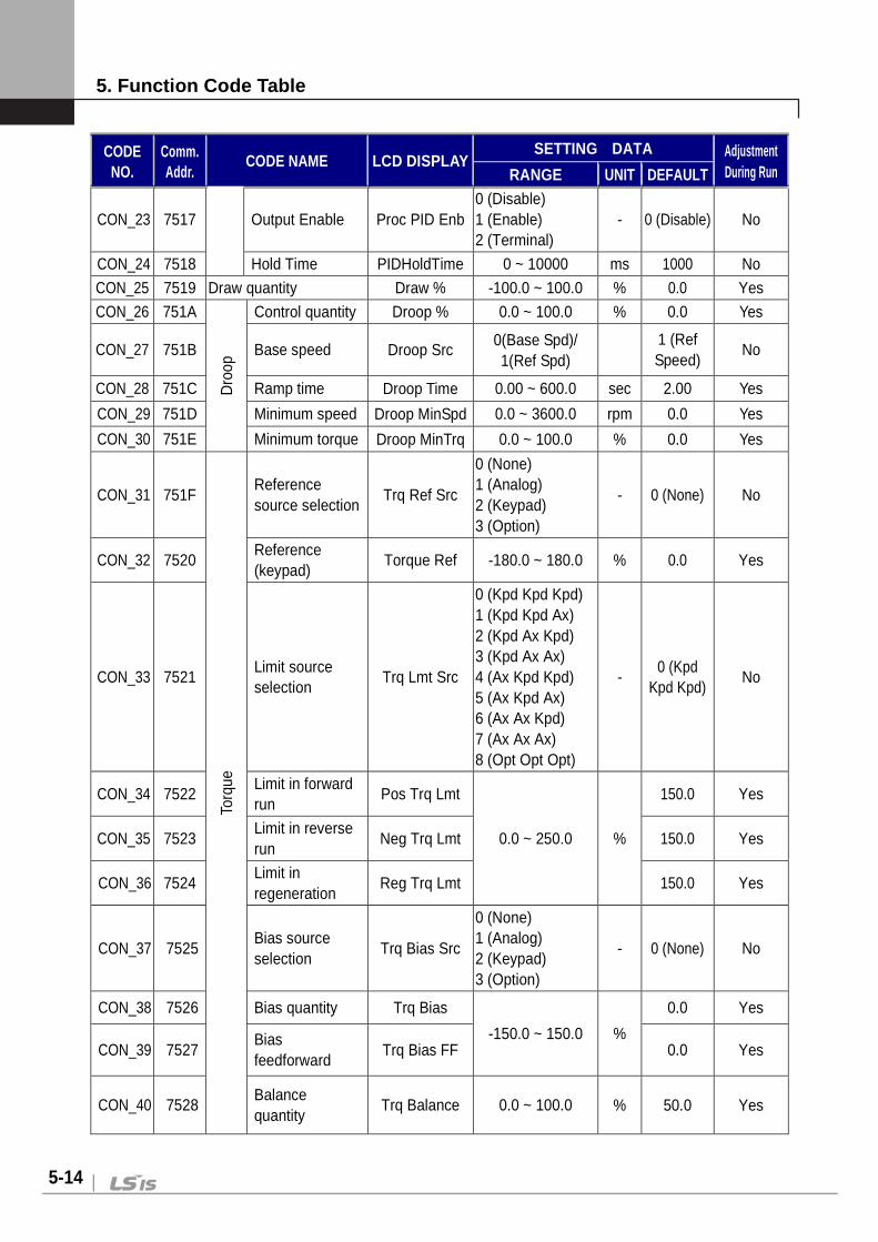
5. Function Code Table
5-14
CODE NO.
Comm. Addr.
CODE NAME LCD DISPLAY SETTING DATA Adjustment
During Run RANGE UNIT DEFAULT
CON_23 7517 Output Enable Proc PID Enb 0 (Disable) 1 (Enable) 2 (Terminal)
- 0 (Disable) No
CON_24 7518 Hold Time PIDHoldTime 0 ~ 10000 ms 1000 No
CON_25 7519 Draw quantity Draw % -100.0 ~ 100.0 % 0.0 Yes
CON_26 751A
Dro
op
Control quantity Droop % 0.0 ~ 100.0 % 0.0 Yes
CON_27 751B Base speed Droop Src 0(Base Spd)/ 1(Ref Spd)
1 (Ref Speed)
No
CON_28 751C Ramp time Droop Time 0.00 ~ 600.0 sec 2.00 Yes
CON_29 751D Minimum speed Droop MinSpd 0.0 ~ 3600.0 rpm 0.0 Yes
CON_30 751E Minimum torque Droop MinTrq 0.0 ~ 100.0 % 0.0 Yes
CON_31 751F
Torq
ue
Reference source selection
Trq Ref Src
0 (None) 1 (Analog) 2 (Keypad) 3 (Option)
- 0 (None) No
CON_32 7520 Reference (keypad)
Torque Ref -180.0 ~ 180.0 % 0.0 Yes
CON_33 7521 Limit source selection
Trq Lmt Src
0 (Kpd Kpd Kpd) 1 (Kpd Kpd Ax) 2 (Kpd Ax Kpd) 3 (Kpd Ax Ax) 4 (Ax Kpd Kpd) 5 (Ax Kpd Ax) 6 (Ax Ax Kpd) 7 (Ax Ax Ax) 8 (Opt Opt Opt)
- 0 (Kpd
Kpd Kpd) No
CON_34 7522 Limit in forward run
Pos Trq Lmt
0.0 ~ 250.0 %
150.0 Yes
CON_35 7523 Limit in reverse run
Neg Trq Lmt 150.0 Yes
CON_36 7524 Limit in regeneration
Reg Trq Lmt 150.0 Yes
CON_37 7525 Bias source selection
Trq Bias Src
0 (None) 1 (Analog) 2 (Keypad) 3 (Option)
- 0 (None) No
CON_38 7526 Bias quantity Trq Bias
-150.0 ~ 150.0 %
0.0 Yes
CON_39 7527 Bias feedforward
Trq Bias FF 0.0 Yes
CON_40 7528 Balance quantity
Trq Balance 0.0 ~ 100.0 % 50.0 Yes

5. Function Code Table
5-15
CODE NO.
Comm. Addr.
CODE NAME LCD DISPLAY SETTING DATA Adjustment
During Run RANGE UNIT DEFAULT
CON_54 7536
Spe
ed S
earc
h
Speed Search selection
Speed Search 0000~ 1111 (Bit setting)
- 0100 No
CON_75 754B Speed Search time 4)
SS Time 10 ~ 60000 ms 300 No
CON_76 754C Speed Search P gain 4)
SS P Gain 1.0 ~ 300.0 % 100.0 Yes
CON_77 754D Speed Search I gain 4)
SS I Gain 1.0 ~ 300.0 % 100.0 Yes
CON_78 754E Speed Search LPF 4)
SS LPF 0.1 ~ 300.0 ms 33.3 Yes
CON_79 754F Speed limit of Speed/Torque switch-over
Spd Lmt Src 0.1 ~
Max Speed rpm 1800.0 No
CON_80 7550 Speed bias of speed/torque
SpdLmtBias 100.0 ~
Max Speed rpm 100.0 No
Note)
1) It will be displayed only when the E/L_IO board is installed.
2) It will be displayed only when the SYNC_IO board is installed.
3) It will be displayed when CON_21 (Process PID type) is set to SpeedSet.
4) It will be displayed when CON_01 is set to Sensorless.
5.6. User group (USR_[][])
CODE NO.
Comm. Addr.
CODE NAME LCD DISPLAY SETTING DATA Adjustment
During RunRANGE UNIT DEFAULT
USR_00 - Select Code number Jump Code 1 ~ 67 - - Yes
USR_01 -
Initialize to the initial
value adequate to the
application
Macro Init User Define
E/L -
User
Define No
USR_02 - User data save User Save No / Yes - No No
USR_03 - Recall saved User
Data. User Recall No / Yes -- No No
USR_04 - User Group Data User Grp - - - No

5. Function Code Table
5-16
5.7. Second motor Group (2nd_[][])
CODE NO.
Comm. Addr. CODE NAME LCD DISPLAY
SETTING DATA Adjustment During Run RANGE UNIT DEFAULT
2nd_00 - Jump for quick view Jump Code 1 ~ 37 - - Yes
2nd_01 7801
2nd
Mot
or
Control mode setting 2nd Ctl Mode 1 (Speed) 2 (Torque) - 1 (Speed) No
2nd_02 7802 Max. speed 2nd Max Spd 400.0 ~ 3600.0 rpm 1800.0 No
2nd_04 7804 Multi-step speed 0 2nd Spd 0 0.0 ~ 2nd_02 rpm 0.0 Yes
2nd_05 7805 S ratio 1 in acceleration start
2nd Acc S St
0.0 ~ 50.0 %
0.0 No
2nd_06 7806 S ratio 2 in acceleration end
2nd Acc S Ed 0.0 No
2nd_07 7807 S ratio 1 in deceleration start
2nd Dec S St 0.0 No
2nd_08 7808 S ratio 2 in deceleration end
2nd Dec S Ed 0.0 No
2nd_09 7809 Acc./Dec. time scale Time scale 2
0 (0.01 sec) 1 (0.1 sec)
- 0 (0.01
sec) No
2nd_10 780A Acceleration time 2nd Acc time 0.00 ~ 6000.0 sec
10.00 Yes
2nd_11 780B Deceleration time 2nd Dec time 10.00 Yes
2nd_12 780C Cooling method 2nd Cool Mtd 0 (Self-cool) 1 (Forced-cool) - 0
(Self-cool) Yes
2nd_13 780D Encoder pulse no. 2nd Enc # 360 ~ 4096 - 1024 No
2nd_14 780E Encoder direction setting 2nd Enc Dir 0 (A Phase Lead)
1 (B Phase Lead) - 0 (A Phase Lead) No
2nd_15 780F Encoder error check enable 2nd Enc chk 0 (No)
1 (Yes) - 1 (Yes) No
2nd_16 7810 Encoder LPF time constant 2nd Enc LPF 0 ~ 100 ms 1 Yes
2nd_18 7812 Base speed 2nd BaseSpd 300.0 ~ 3600.0 rpm 1800.0 No
2nd_19 7813 Capacity selection Motor select Refer to ‘PAR_07’ kW 2 (5.5) No
2nd_20 7814 User defined motor selection UserMotorSel 1) 0.7 ~ 500 kW 5.5 No
2nd_21 7815 Rated voltage 2nd R-Volt 120 ~ 560 V - No
2nd_22 7816 Number of poles 2nd Pole # 2 ~ 12 - 4 No
2nd_23 7817 Efficiency 2nd Mot Eff. 70 ~ 100 % - Yes
2nd_24 7818 Rated slip 2nd R-Slip 10 ~ 250 rpm - Yes
2nd_25 7819 Rated current 2nd R-Curr 1.0 ~ 1000.0 A - Yes
2nd_26 781A Flux current 2nd Flx Cur 0.0 ~ 70% of 2nd_25 A - Yes
2nd_27 781B Motor time constant 2nd Mot Tr 30 ~ 3000 ms - Yes
2nd_28 781C Leakage nductance 2nd Mot Ls 0.00 ~ 500.00 mH - Yes
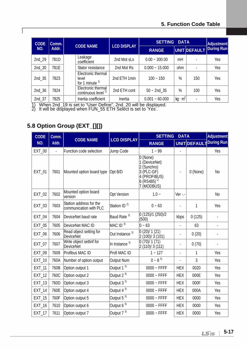
5. Function Code Table
5-17
CODE NO.
Comm. Addr. CODE NAME LCD DISPLAY
SETTING DATA Adjustment During Run RANGE UNIT DEFAULT
2nd_29 781D Leakage coefficient 2nd Mot sLs 0.00 ~ 300.00 mH - Yes
2nd_30 781E Stator resistance 2nd Mot Rs 0.000 ~ 15.000 ohm - Yes
2nd_35 7823 Electronic thermal level for 1 minute 2)
2nd ETH 1min 100 ~ 150 % 150 Yes
2nd_36 7824 Electronic thermal continuous level 2) 2nd ETH cont 50 ~ 2nd_35 % 100 Yes
2nd_37 7825 Inertia coefficient Inertia 0.001 ~ 60.000 kg·m2 - Yes 1) When 2nd_19 is set to “User Define”, 2nd_20 will be displayed. 2) It will be displayed when FUN_55 ETH Select is set to ‘Yes’.
5.8 Option Group (EXT_[][])
CODE NO.
Comm. Addr.
CODE NAME LCD DISPLAY SETTING DATA Adjustment
During Run RANGE UNIT DEFAULT
EXT_00 - Function code selection Jump Code 1 ~ 99 - Yes
EXT_01 7601 Mounted option board type Opt B/D
0 (None) 1 (DeviceNet) 2 (Synchro) 3 (PLC-GF) 4 (PROFIBUS) 6 (RS485) 1) 7 (MODBUS)
- 0 (None) No
EXT_02 7602 Mounted option board version Opt Version 1.0 ~ Ver -.- No
EXT_03 7603 Station address for the communication with PLC Station ID 2) 0 ~ 63 - 1 Yes
EXT_04 7604 DeviceNet baud rate Baud Rate 3) 0 (125)/1 (250)/2 (500) kbps 0 (125) -
EXT_05 7605 DeviceNet MAC ID MAC ID 3) 0 ~ 63 - 63 -
EXT_06 7606 Read object setting for DeviceNet Out Instance 3) 0 (20)/ 1 (21)
2 (100)/ 3 (101) - 0 (20) -
EXT_07 7607 Write object settinf for DeviceNet In Instance 3) 0 (70)/ 1 (71)
2 (110)/ 3 (111) - 0 (70) -
EXT_09 7609 Profibus MAC ID Profi MAC ID 1 ~ 127 - 1 Yes
EXT_10 760A Number of option output Output Num 0 ~ 8 5) - 3 Yes
EXT_11 760B Option output 1 Output 1 5) 0000 ~ FFFF HEX 0020 Yes
EXT_12 760C Option output 2 Output 2 5) 0000 ~ FFFF HEX 000E Yes
EXT_13 760D Option output 3 Output 3 5) 0000 ~ FFFF HEX 000F Yes
EXT_14 760E Option output 4 Output 4 5) 0000 ~ FFFF HEX 000A Yes
EXT_15 760F Option output 5 Output 5 5) 0000 ~ FFFF HEX 0000 Yes
EXT_16 7610 Option output 6 Output 6 5) 0000 ~ FFFF HEX 0000 Yes
EXT_17 7611 Option output 7 Output 7 5) 0000 ~ FFFF HEX 0000 Yes

5. Function Code Table
5-18
CODE NO.
Comm. Addr.
CODE NAME LCD DISPLAY SETTING DATA Adjustment
During Run RANGE UNIT DEFAULT
EXT_18 7612 Option output 8 Output 8 5) 0000 ~ FFFF HEX 0000 Yes EXT_19 7613 Number of option input Input Num 0 ~ 8 6) - 2 Yes EXT_20 7614 Option input 1 Input 1 6) 0000 ~ FFFF HEX 0502 No EXT_21 7615 Option input 2 Input 2 6) 0000 ~ FFFF HEX 0500 No EXT_22 7616 Option input 3 Input 3 6) 0000 ~ FFFF HEX 0000 No EXT_23 7617 Option input 4 Input 4 6) 0000 ~ FFFF HEX 0000 No EXT_24 7618 Option input 5 Input 5 6) 0000 ~ FFFF HEX 0000 No EXT_25 7619 Option input 6 Input 6 6) 0000 ~ FFFF HEX 0000 No EXT_26 761A Option input 7 Input 7 6) 0000 ~ FFFF HEX 0000 No EXT_27 761B Option input 8 Input 8 6) 0000 ~ FFFF HEX 0000 No
EXT_30 761E 485 communication mode Parity/Stop 1)
0 (8None/1Stop) 1 (8None/2Stop) 2 (8Even/1Stop) 3 (8Odd/1Stop)
- 0
(8None/ 1Stop)
Yes
EXT_31 761F Delay time of 485 communication response Delay Time 1) 2 ~ 1000 ms 5 Yes
EXT_32 7620 Station address for built-in 485 Int485 St ID 1 ~ 250 - 2 Yes
EXT_33 7621 Built-in 485 baudrate Int485 Baud
0 (1200 bps) 1 (2400 bps) 2 (4800 bps) 3 (9600 bps) 4 (19200 bps) 5 (38400 bps)
- 3 (9600 bps) Yes
EXT_34 7622 Built-in 485 communication mode Int485 Mode
0 (8None/1Stop) 1 (8None/2Stop) 2 (8Even/1Stop) 3 (8Odd/1Stop)
- - Yes
EXT_35 7623 Delay time for built-in 485 communication response Int485 Delay 2 ~ 1000 - 0 (None) Yes
EXT_36 7624 Run method when the command of built-in 485 is lost.
Int485 LostC 0 (None) 1 (FreeRun) 2 (Stop)
- - Yes
EXT_37 7625 Decision time for losing the command of built-in 485 Int485 LostT 1.0 ~ 30.0 - - Yes
EXT_98 7662 Profibus data swap Selection SWAP Sel 0 (No) / 1 (Yes) - 0 (No) No
EXT_99 7663 Update for communication parameter changes Comm UpDate 4) 0 (No) / 1 (Yes) - 0 (No) No
1) It will be displayed when RS-485 communication option board is installed.
2) It will be displayed when PLC-GF communication option board is installed.
3) It will be displayed when DeviceNet communication option board is installed.
4) Itwill be displayed when Profibus communication option b oard is installed.
5) From EXT_11 to EXT_18 (Option ouput) are displayed according to the number from EXT_11.
6) From EXT_20 to EXT_27 (Option input) are displayed according to the number from EXT_19.
Refer to the appropriate option manual.
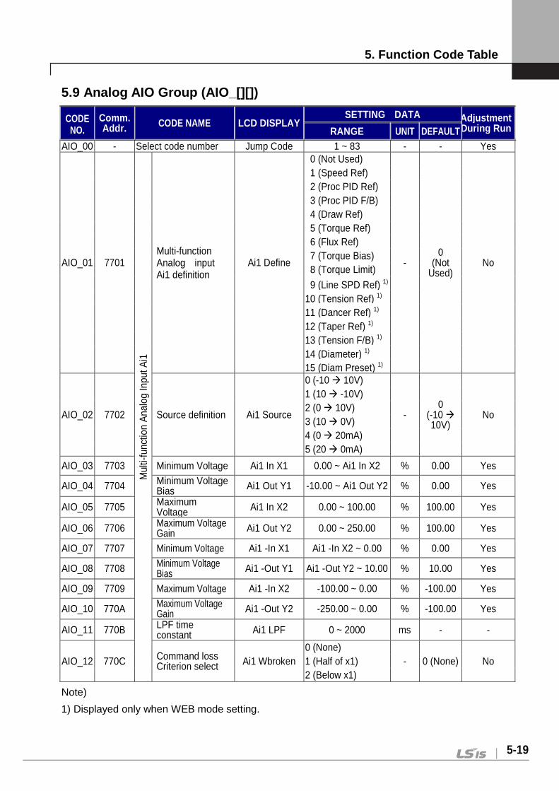
5. Function Code Table
5-19
5.9 Analog AIO Group (AIO_[][])
CODE NO.
Comm. Addr. CODE NAME LCD DISPLAY
SETTING DATA Adjustment During Run RANGE UNIT DEFAULT
AIO_00 - Select code number Jump Code 1 ~ 83 - - Yes
AIO_01 7701
Mul
ti-fu
nctio
n A
nalo
g In
put A
i1
Multi-function Analog input Ai1 definition
Ai1 Define
00 (Not Used)
- 0
(Not Used)
No
01 (Speed Ref) 02 (Proc PID Ref) 03 (Proc PID F/B) 04 (Draw Ref) 05 (Torque Ref) 06 (Flux Ref) 07 (Torque Bias) 08 (Torque Limit)
09 (Line SPD Ref) 1) 10 (Tension Ref) 1) 11 (Dancer Ref) 1) 12 (Taper Ref) 1) 13 (Tension F/B) 1) 14 (Diameter) 1) 15 (Diam Preset) 1)
AIO_02 7702 Source definition Ai1 Source
0 (-10 10V)
- 0
(-10 10V)
No
1 (10 -10V) 2 (0 10V) 3 (10 0V) 4 (0 20mA) 5 (20 0mA)
AIO_03 7703 Minimum Voltage Ai1 In X1 0.00 ~ Ai1 In X2 % 0.00 Yes
AIO_04 7704 Minimum Voltage Bias Ai1 Out Y1 -10.00 ~ Ai1 Out Y2 % 0.00 Yes
AIO_05 7705 Maximum Voltage Ai1 In X2 0.00 ~ 100.00 % 100.00 Yes
AIO_06 7706 Maximum Voltage Gain Ai1 Out Y2 0.00 ~ 250.00 % 100.00 Yes
AIO_07 7707 Minimum Voltage Ai1 -In X1 Ai1 -In X2 ~ 0.00 % 0.00 Yes
AIO_08 7708 Minimum Voltage Bias Ai1 -Out Y1 Ai1 -Out Y2 ~ 10.00 % 10.00 Yes
AIO_09 7709 Maximum Voltage Ai1 -In X2 -100.00 ~ 0.00 % -100.00 Yes
AIO_10 770A Maximum Voltage Gain Ai1 -Out Y2 -250.00 ~ 0.00 % -100.00 Yes
AIO_11 770B LPF time constant Ai1 LPF 0 ~ 2000 ms - -
AIO_12 770C Command loss Criterion select Ai1 Wbroken
0 (None) - 0 (None) No 1 (Half of x1)
2 (Below x1)
Note)
1) Displayed only when WEB mode setting.

5. Function Code Table
5-20
CODE NO.
Comm. Addr.
CODE NAME LCD DISPLAY SETTING DATA Adjustment
During Run RANGE UNIT DEFAULT
AIO_13 770D M
ulti-
func
tion
Ana
log
Inpu
t Ai2
Multi-function Analog input Ai2 Definition Ai2 Define
Refer to AIO_01~12
AIO_14 770E Source definition Ai2 Source
AIO_15 770F Minimum Voltage Ai2 In X1
AIO_16 7710 Minimum Voltage Bias Ai2 Out Y1
AIO_17 7711 Maximum Voltage Ai2 In X2
AIO_18 7712 Maximum Voltage Gain Ai2 Out Y2
AIO_19 7713 Minimum Voltage Ai2 -In X1
AIO_20 7714 Minimum Voltage Bias Ai2 -Out Y1
AIO_21 7715 Maximum Voltage Ai2 -In X2
AIO_22 7716 Maximum Voltage Gain Ai2 -Out Y2
AIO_23 7717 LPF time constant Ai2 LPF
AIO_24 7718 Loss command Criterion select Ai2 Wbroken
AIO_25 7719
Mul
ti-fu
nctio
n A
nalo
g In
put A
i3
Multi-function Analog input Ai3 Definition Ai3 Define
Refer to AIO_01 ∫
Possible to select NTC motor
17 (Use Mot NTC)
0 (Not
Used) No
AIO_26 771A Source Definition Ai3 Source
0 (-10 10V)
- 0
(-10 10V)
No 1 (10 -10V) 2 (0 10V) 3 (10 0V)
AIO_27 771B Minimum Voltage Ai3 In X1
Refer to AIO_03~12
AIO_28 771C Minimum Voltage Bias
Ai3 Out Y1
AIO_29 771D Maximum Voltage Ai3 In X2
AIO_30 771E Maximum Voltage Gain
Ai3 Out Y2
AIO_31 771F Minimum Voltage Ai3 -In X1
AIO_32 7720 Minimum Voltage Bias
Ai3 -Out Y1
AIO_33 7721 Maximum Voltage Ai3 -In X2
AIO_34 7722 Maximum Voltage Gain
Ai3-Out Y2
AIO_35 7723 Input LPF time constant
Ai3 LPF
AIO_36 7724 Multi-function Analog input Command loss criterion select
Ai3 Wbroken

5. Function Code Table
5-21
CODE NO.
Comm. Addr. Code Name LCD DISPLAY SETTING DATA Adjustment
During Run RANGE UNIT DEFAULT
AIO_37 7725
Mul
ti-fu
nctio
n A
nalo
g In
put A
i4
Multi-function Analog input Ai4 Definition 1) Ai4 Define
AIO_38 7726 Source Definition 1) Ai4 Source
AIO_39 7727 Minimum Voltage 1) Ai4 In X1
AIO_40 7728 Minimum Voltage Bias 1) Ai4 Out Y1
AIO_41 7729 Maximum Voltage 1) Ai4 In X2
AIO_42 772A Maximum Voltage Gain 1) Ai4 Out Y2
AIO_43 772B Minimum Voltage 1) Ai4 -In X1
AIO_44 772C Minimum Voltage Bias 1) Ai4 -Out Y1
AIO_45 772D Maximum Voltage 1) Ai4 -In X2
AIO_46 772E Maximum Voltage Gain 1) Ai4 -Out Y2
AIO_47 772F Output LPF time constant1) Ai4 LPF
AIO_48 7730 Command loss criterion select1) Ai4 Wbroken
AIO_49 7731
Mul
ti-fu
nctio
n A
nalo
g In
put A
i5
Multi-function Analog input Ai5 Definition 1)
Ai5 Define
Refer to AIO_01 ∫
When using EXTN_I/O motor NTC/PTC function is
available at Ai5 17(Use Mot NTC)
0 (Not
Used) No
AIO_50 7732 Source Definition 1) Ai5 Source
0 (-10 10V)
- 0 (-10
10V) No 1 (10 -10V)
2 (0 10V) 3 (10 0V)
AIO_51 7733 Minimum Voltage 1) Ai5 In X1
Refer to AIO_03~12.
AIO_52 7734 Minimum Voltage Bias 1) Ai5 Out Y1
AIO_53 7735 Maximum Voltage 1) Ai5 In X2
AIO_54 7736 Maximum Voltage Gain 1) Ai5 Out Y2
AIO_55 7737 Minimum Voltage 1) Ai5 -In X1
AIO_56 7738 Minimum Voltage Bias 1) Ai5 -Out Y1
AIO_57 7739 Maximum Voltage1) Ai5 -In X2
AIO_58 773A Maximum Voltage Gain 1) Ai5 -Out Y2
AIO_59 773B Input LPF time constant 1) Ai5 LPF
AIO_60 773C Command loss criterion select 1) Ai5 Wbroken
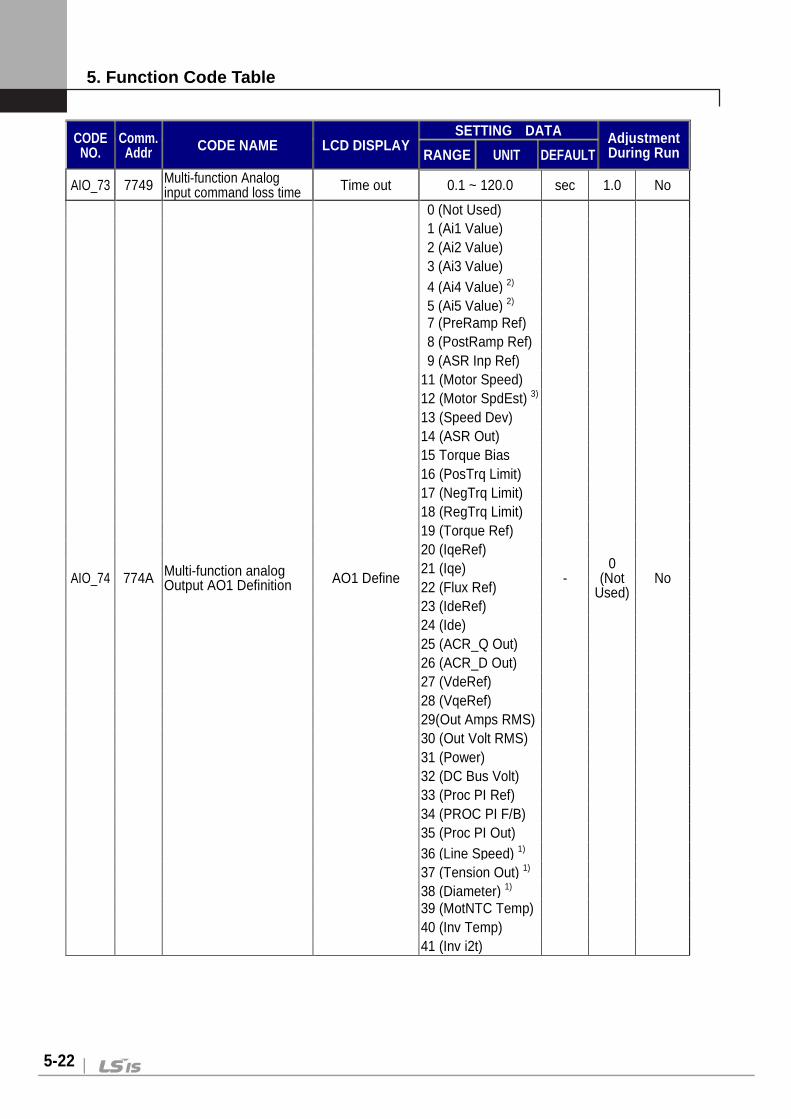
5. Function Code Table
5-22
CODE NO.
Comm. Addr CODE NAME LCD DISPLAY
SETTING DATA Adjustment During Run RANGE UNIT DEFAULT
AIO_73 7749 Multi-function Analog input command loss time Time out 0.1 ~ 120.0 sec 1.0 No
AIO_74 774A Multi-function analog Output AO1 Definition AO1 Define
0 (Not Used)
- 0
(Not Used)
No
1 (Ai1 Value) 2 (Ai2 Value) 3 (Ai3 Value) 4 (Ai4 Value) 2) 5 (Ai5 Value) 2) 7 (PreRamp Ref) 8 (PostRamp Ref) 9 (ASR Inp Ref)
11 (Motor Speed) 12 (Motor SpdEst) 3) 13 (Speed Dev) 14 (ASR Out) 15 Torque Bias 16 (PosTrq Limit) 17 (NegTrq Limit) 18 (RegTrq Limit) 19 (Torque Ref) 20 (IqeRef) 21 (Iqe) 22 (Flux Ref) 23 (IdeRef) 24 (Ide) 25 (ACR_Q Out) 26 (ACR_D Out) 27 (VdeRef) 28 (VqeRef) 29(Out Amps RMS) 30 (Out Volt RMS) 31 (Power) 32 (DC Bus Volt) 33 (Proc PI Ref) 34 (PROC PI F/B) 35 (Proc PI Out) 36 (Line Speed) 1) 37 (Tension Out) 1) 38 (Diameter) 1) 39 (MotNTC Temp) 40 (Inv Temp) 41 (Inv i2t)

5. Function Code Table
5-23
CODE NO.
Comm. Addr. CODE NAME LCD
DISPLAY
Setting Data Adjustment During Run Range Unit Default
AIO_75 774B M
ulti-
func
tion
Ana
log
Inpu
t AO
1 Source Definition AO1 Source
0 (-10 10V) 1 (10 -10V) 2 (0 10V) 3 (10 0V)
- 0 (-10 10V) No
AIO_76 774C Bias AO1 Bias -100.0 ~ AIO_77 % 0.0 No AIO_77 774D Gain AO1 Gain 0.0 ~ 500.0 % 100.0 No AIO_78 774E Bias AO1 Bias AIO_79 ~ 0.0 % 0.0 Yes
AIO_79 774F Gain AO1 Gain 0.0 ~ -500.0 % -100.0 Yes
AIO_80 7750 Absolute value setting AO1 ABS 0 (No) / 1 (Yes) - 0 (No) No
AIO_81 7751 Definition AO2 Define
Refer to AIO_74~78
AIO_82 7752 Source Definition AO2 Source AIO_83 7753 Bias AO2 Bias AIO_84 7754 Gain AO2 Gain AIO_85 7755 Bias AO2 Bias AIO_86 7756 Gain AO2 Gain
AIO_87 7757 Absolute value setting AO2 ABS
Note)
1) Displayed only when WEB mode setting.
2) It is available when Extension I/O (EXTN_I/O) is applied.
3) It will be displayed when CON_01 is set to ‘Sensorless’.

5. Function Code Table
5-24
5.10 Sensorless control Group (SLS_[][]) 1)
CODE NO.
Comm. Addr. CODE NAME LCD DISPLAY
Setting Data Adjustment During Run Range Unit Default
SLS_00 - Function code selection Jump Code 1 ~ 23 Yes
SLS_01 7D01 Flux estimation time with sensorless control Flux BD Time 100 ~ 60000 ms 500 Yes
SLS_02 7D02 P gain for flux estimation FlxEst PGain 0.1 ~ 999.9 % 100.0 Yes
SLS_03 7D03 I gain for flux estimation FlxEst IGain 0.0 ~ 999.9 % 100.0 Yes
SLS_04 7D04 cut-off frequency for sensorless ASR ASR Cut-Off 1.0 ~ 600.0 20.0 Yes
SLS_05 7D05 Sensorless ASR P gain 1 ASR P Gain1 0.1 ~ 999.9 % 100.0 Yes
SLS_06 7D06 Sensorless ASR I gain 1 ASR I Gain1 0.1 ~ 999.9 % 100.0 Yes
SLS_07 7D07 Sensorless ASR LPF 1 ASR LPF1 0 ~ 20000 ms 0 Yes
SLS_08 7D08 Sensorless ASR P gain 2 ASR P Gain2 0.1 ~ 999.9 % 50.0 Yes
SLS_09 7D09 Sensorless ASR I gain 2 ASR I Gain2 0.1 ~ 999.9 % 50.0 Yes
SLS_10 7D0A Sensorless ASR LPF 2 ASR LPF2 0 ~ 20000 ms 0 Yes
SLS_11 7D0B Switch-over ramp for sensorless ASR ASR RAMP 10 ~ 10000 ms 1000 Yes
SLS_12 7D0C Sensorless ASR target speed ASR TarSpd 0.0 ~ 3600.0 rpm 0.0 No
SLS_13 7D0D Sensorless P gain SpdEst PGain 0.1 ~ 999.9 % 100.0 Yes
SLS_14 7D0E Sensorless I gain SpdEst IGain 0.1 ~ 999.9 % 100.0 Yes
SLS_15 7D0F Cut-off frequency for sensorless ACR ACR Cut-off 10.0 ~ 3000.0 1200.0 Yes
SLS_16 7D10 Regerneration avoidance selection ZeroAvd Sel 0 (No) / 1 (Yes) 1 (Yes) No
SLS_17 7D11 P gain of sensored speed controller SensoredKp 0 ~ 10.0000 0.0000 No
SLS_18 7D12 I gain of sensored speed controller SensoredKi 0 ~ 10.0000 0.0000 No
SLS_19 7D13 P gain of sensorless speed controller SensorlessKp 0 ~ 10.0000 0.0000 No
SLS_20 7D14 I gain of sensorless speed controller SensorlessKi 0 ~ 10.0000 0.0000 No
SLS_21 7D15 Command of flux estimation FluxEst Ref 0.0000 ~ 6.5535 0.0000 No
SLS_22 7D16 Feedback of flux estimation FluxEst Fbk 0.0000 ~ 6.5535 0.0000 No
SLS_23 7D17 Rs scale Rs Scale 100.0 ~ 200.0 % 120.0 Yes
1) It will be displayed when CON_01 is set to Sensorless.
6. Inspection and Replacement
6-1
Chapter 6 – Inspection and replacement LS Vector Inverter, STARVERT-iV5, is an industrial electronic product that adopts up-to-date semiconductor device. It may have a failure caused by the ambient environment such as temperature, humidity, vibration, etc. or an excessive use of the component over its duration. It requires a routine checking to prevent such failure in advance. 6.1 Precautions
CAUTION Before starting the maintenance work, the operator must check out
the power input of the inverter. Large-capacity electrolytic condenser in the power electronic circuit
remains charged with power even after the power is off. So be sure to start the maintenance work after you acknowledged the power has been completely discharged using a proper tester.
Be sure to use a rectifier type volt meter to obtain an accurate voltage when directly measuring the output voltage of inverter. General volt meter or digital volt meter may result in spurious operation or indicate wrong value due to high frequency PWM output voltage of the inverter.
6.2 Checking Points
Electronic product is not intended for a permanent use. When it exceeds the duration even under the normal service environment, the product may have trouble in its operation due to change in the nature of the parts. To prevent such circumstance, it requires a routine and regular checking.
Especially if you use it under the following environment, have it checked with a shorter interval than the regular checking.
When the temperature is relatively high in the installed place
When the product is operated with a frequent start and stop
When the input AC power and load vary seriously
When it has severe vibration or shock
When there is corrosive gas, combustible gas, oil sludge, dust, salts, metal powder, etc

6. Inspection and Replacement
6-2
CAUTION The failure of the device used in the inverter may not be predicted
in advance. The failure of the device may cause the error of input power fuse or the fault trip. If you are suspicious of the failure of device, please contact our sales representative.
6.3 Routine Checking
Are
a
Che
ckin
g po
ints
Des
crip
tion
How
to
Che
ck
Judg
men
t C
riter
ion
Inst
rum
ent
Ove
rvie
w
Am
bien
t
envi
ronm
ent
Check ambient temperature, humidity, existence of dust, etc..
See the Caution for Safety.
Ambient temperature should be -10 ~ +40 degree C; Freezing is not allowed; Ambient humidity to be 50% or less; Dew is not allowed. T
empe
ratu
re m
eter
, H
umid
ity m
eter
, R
ecor
der
Ent
ire
syst
em
Isn't there any vibration or unusual sound?
Judgement by visual or auditory sense.
There must be no unusual record. -
Pow
er,
Vol
tage
Is the main circuit voltage normal
Check the voltage among R, S, and T phases on the inverter terminal .block
-
Dig
ital
Mul
ti M
eter
/Tes
ter
Mai
n ci
rcui
t
Fla
t con
dens
er 1) Isn't the liquid
inside leaked?
2) Isn't the safety vent protruded? No sagging phenomenon?
Check 1) and 2) by eyes.
There must be no unusual result from 1) and 2).
-
Coo
ling
syst
em
Coo
ling
fan
1) Isn't there any unusual vibration or unusual sound?
1) Turn it using hand with the power Off.
1) Rotate it softly -

6. Inspection and Replacement
6-3
Are
a
Che
ckin
g po
ints
Des
crip
tion
How
to
Che
ck
Judg
men
t C
riter
ion
Inst
rum
ent
Inve
rter
, Mot
or
Do they have excessive heat?
1) Check if it is from overload or not.
2) Fasten the screw tightly.
3) Check if the inverter's heat sink is polluted.
4) Check the ambient temperature.
There must be no unusual record.
Tem
pera
ture
met
er
Indi
cato
r
Met
er
Is the indicator value normal
Check the indicator value on the display of the panel surface.
Check the value under the regulation and standard value.
Vol
t Met
er,
Cur
rent
M
eter
, etc
.
Mot
or
Ent
ire s
yste
m
1) Isn't there any unusual vibration or unusual sound?
2) Isn't there any unusual smell?
1) Check by ear, hand, and eye.
2) Check overheat, damage, etc.
3) Check the area connected with the machine.
4) Measure the vibration of the motor.
5) Fasten the screw on the junction tightly.
There must be no unusual record. -
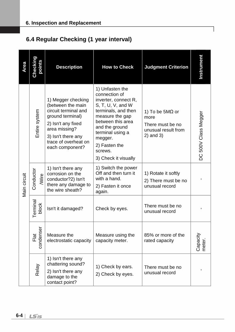
6. Inspection and Replacement
6-4
6.4 Regular Checking (1 year interval)
Are
a
Che
ckin
g po
ints
Description How to Check Judgment Criterion
Inst
rum
ent
Mai
n ci
rcui
t
Ent
ire s
yste
m
1) Megger checking (between the main circuit terminal and ground terminal)
2) Isn't any fixed area missing?
3) Isn't there any trace of overheat on each component?
1) Unfasten the connection of inverter, connect R, S, T, U, V, and W terminals, and then measure the gap between this area and the ground terminal using a megger.
2) Fasten the screws.
3) Check it visually
1) To be 5MΩ or more
There must be no unusual result from 2) and 3)
DC
500
V C
lass
Meg
ger
Con
duct
or
/Wire
1) Isn't there any corrosion on the conductor?2) Isn't there any damage to the wire sheath?
1) Switch the power Off and then turn it with a hand.
2) Fasten it once again.
1) Rotate it softly
2) There must be no unusual record
-
Ter
min
al
bloc
k
Isn't it damaged? Check by eyes. There must be no unusual record
-
Fla
t co
nden
ser
Measure the electrostatic capacity
Measure using the capacity meter.
85% or more of the rated capacity
Cap
acity
m
eter
.
Rel
ay
1) Isn't there any chattering sound?
2) Isn't there any damage to the contact point?
1) Check by ears.
2) Check by eyes.
There must be no unusual record
-
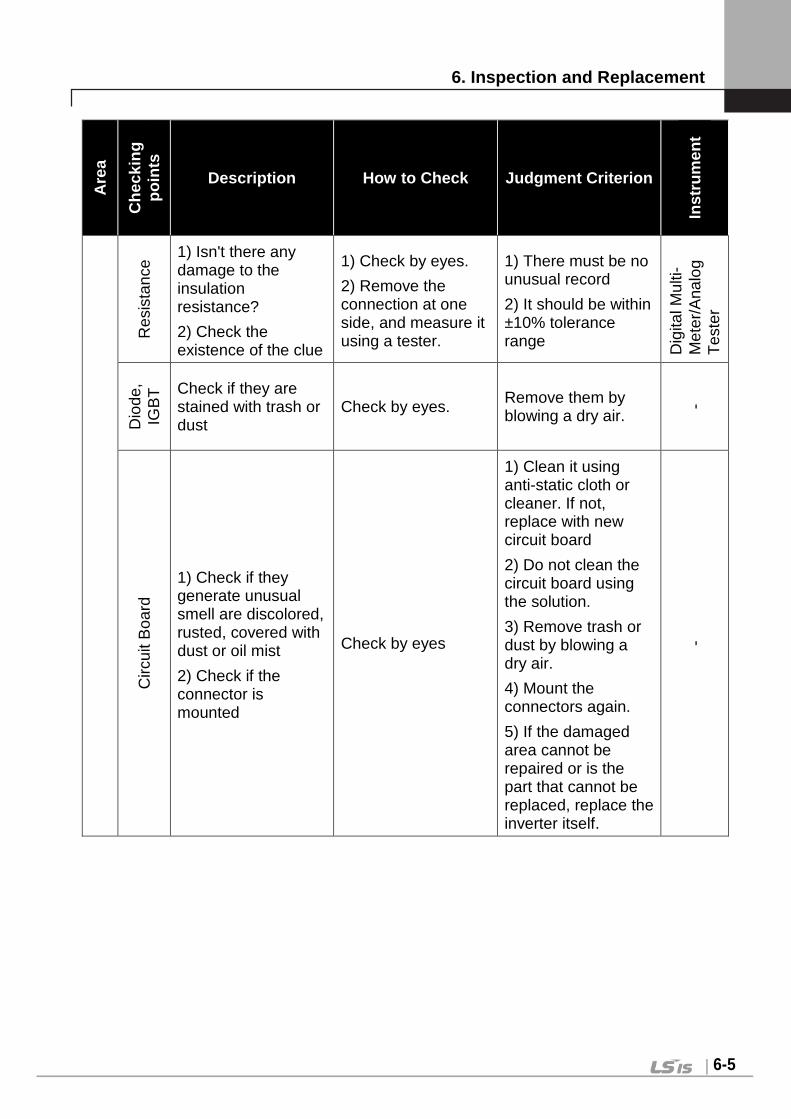
6. Inspection and Replacement
6-5
Are
a
Che
ckin
g po
ints
Description How to Check Judgment Criterion
Inst
rum
ent
Res
ista
nce
1) Isn't there any damage to the insulation resistance?
2) Check the existence of the clue
1) Check by eyes.
2) Remove the connection at one side, and measure it using a tester.
1) There must be no unusual record
2) It should be within ±10% tolerance range D
igita
l Mul
ti-M
eter
/Ana
log
Tes
ter
Dio
de,
IGB
T Check if they are
stained with trash or dust
Check by eyes. Remove them by blowing a dry air.
-
Circ
uit B
oard
1) Check if they generate unusual smell are discolored, rusted, covered with dust or oil mist
2) Check if the connector is mounted
Check by eyes
1) Clean it using anti-static cloth or cleaner. If not, replace with new circuit board
2) Do not clean the circuit board using the solution.
3) Remove trash or dust by blowing a dry air.
4) Mount the connectors again.
5) If the damaged area cannot be repaired or is the part that cannot be replaced, replace the inverter itself.
-

6. Inspection and Replacement
6-6
Are
a
Che
ckin
g po
ints
Description How to Check Judgment Criterion
Inst
rum
ent
Con
trol
circ
uit p
rote
ctin
g ci
rcui
t
Ope
ratio
n
1) Check the unbalance of the output voltage during the operation of inverter
2) Display circuit must not have any unusual phenomenon after the sequence protecting operation test is done
1) Measure the voltage among the U, V, and W at the Inverter output terminal.
2) Have the inverter protecting circuit output shorted out or open it by force.
1) Balance of inter-phase voltage
200V (400V) Use: Within 4V(8V)
2) Unusual circuit to be operated in sequence
Dig
ital M
ulti-
Met
er/
DC
type
Vol
t Met
er
Coo
ling
Sys
tem
Coo
ling
fan,
C
oolin
g pi
n
1) Isn't there any looseness on the junction?
2) Isn't cooling pin or cooling fan covered with dust
1) Fasten it once again.
2) Check with eyes and then remove dust
1) There must be no unusual record
2) There must be no dust
-
Indi
cato
r
Met
er
Is the indicator value normal?
Check the indicator value on the display of the panel surface.
Check the value under the regulation and standard value
Vol
t Met
er/
Cur
rent
M
eter
, etc
.
6.5 Meggar Test ① For Exterior main circuit, remove all cables from inverter terminals to
ensure that test voltage is not applied to the inverter. ② Use DC 500V meggar and isolate the main power before starting
measurement. If the test voltage is connected to the control circuit, remove all connection cables to the control circuit.
③ Perform the Meggar test only between the common cables connected to the main circuit and ground.

6. Inspection and Replacement
6-7
6.6 Regular Checking (2 year interval)
Are
a
Che
ckin
g po
ints
Description How to Check Judgment Criterion
Inst
rum
ent
Mai
n ci
rcui
t
Ent
ire s
yste
m
Megger Checking (between the main circuit terminal and the ground terminal
Unfasten the connection of the inverter, and then measure the gap among R, S, T, U, V, and W terminals and this area after having them shorted out.
5MΩ or more
DC
500
V C
lass
M
egge
r
Mot
or
Res
ista
nce
Insu
latio
n Megger checking (between the output terminal and the ground terminal)
Unfasten the connection among U, V, and W, and then bind the motor wiring.
5MΩ or more
500V
Cla
ss
Meg
ger
6.7 Replacement Interval and Maintenance of the Key Components
Inverter constitutes a number of electronic parts including semiconductor device. The parts used in the inverter are subject to change as time elapses for its construction or nature. Therefore without any replacement of parts, it may cause failure or deterioration in the performance the inverter. For this reason, it requires regular replacement of the parts.
Name of parts Standard interval for replacement Symptoms How to Replace and
Countermeasure
Cooling Fan 2 ~ 3 years Poor Rotation Replacement into new part
DC Link condenser 5 years Reduction in
Capacity Replacement into new
part
Control Panel Flat Condenser 5 years Reduction in
Capacity Replacement into new
part
Control Board Relay - Poor Operation Replacement into new part

6. Inspection and Replacement
6-8
Name of parts Standard interval for replacement Symptoms How to Replace and
Countermeasure
Braking Resistance - Reduction in
Capacity Replacement into new
part
Duration of the key components is based on the continuous operation at a rated load. Therefore the duration is subject to change depending on the service condition and ambient environment.
6.8 How to Check at Diode Module & IGBT Inspection
1. Remove the power source wire (R, S, T) and the motor output wire (U, V, W) connected from the outside
2. Check and determine whether R, S, T, U, V, W, B1 (or P/L1), N of the inverter terminal block are turned on or not by changing the polarity of the tester between each other.
3. Perform the test after making sure that the electrolytic condenser is discharged.
4. When they are not turned on, they will indicate several mega resistance values. It may indicate several mega resistance values when it is turned on for a moment owing to the influence of electrolytic condenser. When they are turned on, it indicates several Ω ~ dozens of Ω. The indicator value varies depending on the type of module, the type of tester, etc., but such values are shown in a similar range when it is sound product.

7. Troubleshooting and Maintenance
7-1
Chapter 7 – Troubleshooting and maintenance 7.1 Fault Display
CAUTION When a fault occurs, the inverter turns off its output and displays the fault status described below. In this case, the cause must be corrected before the fault can be cleared. If protective function keeps active, it could lead to reduction in product life and damage to the equipment.
Protective function
Keypad display Description
Over Current OC-U OC-V OC-W
The inverter turns off its output when the output current of the inverter flows more than 200% of the inverter rated current.
Ground Fault Protection
Ground Fault
The inverter turns off its output when a ground fault occurs and the ground fault current is more than the internal setting value of the inverter. Over current trip function may protect the inverter when a ground fault occurs due to a low ground fault resistance.
Over voltage protection
Over Voltage
The inverter turns off its output if the DC voltage of the main circuit increases higher than the rated value (200V class: 400V DC, 400V class: 820 V DC) when the motor decelerates or when regenerative energy flows back to the inverter due to a regenerative load. This fault can also occur due to a surge voltage generated at the power supply system.
Low Voltage Protection
Low Voltage
The inverter turns off its output if the DC voltage is below the detection level (200V class: 180Vdc, 400V class: 360Vdc) because insufficient torque or over heating of the motor can occurs when the input voltage of the inverter drops.
Overload Protection Over Load
The inverter turns off its output if the output current of the inverter flows at 180% of the inverter rated current for more than the current limit time (S/W).
Inverter Overload Inv OLT
The inverter turns off its output when the rated current of the inverter flows more than regulation level (150% for 1 minute-Inversely proportional to time).
Heat Sink Over Heat
InvOver Heat
The inverter turns off its output if the heat sink over heats due to a damaged cooling fan or an alien substance in the cooling fan by detecting the temperature of the heat sink.
OHD Open The inverter turns off its output when OHD is opened and

7. Troubleshooting and Maintenance
7-2
Protective function
Keypad display Description
*1) the heat sink is overheated.
Inverter NTC Thermistor
Open
InvThem OP
When inverter NTC Thermistor is open, inverter stops its output.
Motor overheat MotOver Heat
When motor temp exceeds 150 , inverter stops its output to protect motor from overheated.
Motor Thermistor
Error
MotThem Err
When there is an error in Thermistor that measures the temperature of motor, inverter stops its output. (Error—NTC: open , PTC: short-circuit)
Electronic Thermal E-Thermal
The internal electronic thermal of the inverter determines the over heating of the motor. If the motor is overloaded the inverter turns off the output. The inverter cannot protect the motor when driving a multi-pole motor or when driving multiple motors, so consider thermal relays or other thermal protective devices for each motor. Overload capacity: 150% for 1 min.
External fault B Ext Trip-B Use this function if the user needs to turn off the output by an external fault signal.
IGBT Short Arm Short
Arm Short-DB
Inverter output is stopped when IGBT Arm short or output short occurs. (Arm Short-DB is only come under SV110~220iV5)(
Fuse Open Fuse Open The inverter turns off its output by opening the fuse when something is wrong with the main circuit IGBT to protect the wiring from being damaged from short currents
Encoder Error Encoder Err
1) Displayed when Encoder signal fault occurs.(H/W) 2) Displayed when there is a discord of detection time
standard of motor error of PAR-14.(S/W)
BX protection (Instant Cut
Off) BX
Used for the emergency stop of the inverter. The inverter instantly turns off the output when the BX terminal is turned ON, and returns to regular operation when the BX terminal is turned OFF. Take caution when using this function.
Motor overspeed
Over Speed Displayed when motor rotates over 120% its rated speed.
Communication Error
COM Error CPU Error
Displayed when the inverter cannot communicate with the keypad.

7. Troubleshooting and Maintenance
7-3
Protective function
Keypad display Description
H/W Error HW–Diag Displayed when CPU has a problem, and then the inverter blocks the IGBT gating signals.
FAN Lock*1) FAN Lock The inverter turns off its output when there is an Fan Lock.
Encoder Power Error*1)
Enc Power When there is an error in Encoder power source, the inverter turns off its output. Converted to initial screen and displayed “EPR” on the right upper side.
Input Phase Open Input PO
It cuts off the output from the inverter in a condition that a power is not supplied to a phase among the 3-phase input on the enough loads.
Output Phase Open
Output PO It cuts off the output from the inverter through detecting the status of flowing of the current.
AC FAN and M/C Power
Fault
FAN/MC PWR
Displayed when the step down transformer for AC FAN and M/C power input or Input fuse connected to transformer has a fault. (AC input type 30~160kW)
It cuts off the output to prevent the inverter from damage when the power of 220V has not supplied to AC FAN and M/C. (DC input type 230~160kW)
AC FAN Power Fault
FAN PWR
Displayed when the step down transformer for AC FAN and M/C power input or input fuse for transformer has a fault. (AC input type 220kW)
It cuts off the output to prevent the inverter from damage when the power of 220V has not supplied to AC FAN. (DC input type 220kW and AC/DC input type 500kW)
*1) It only comes under SV2800~5000iV5.

7. Troubleshooting and Maintenance
7-4
7.2 Monitoring Fault Condition
7.2.1 Monitoring fault display
Code LCD display Description
DIS_05 OC-U Current fault displayed. (U-phase overcurrent)
Check the current fault display before pressing reset key. pressing [PROG] key and [(Up)],[(Down)] shows operating status at the time of the fault such as output frequency, current, voltage, F/B value, torque current reference/actual value, dc link voltage, input/output terminal status, operating status and run time) and the fault contents. Press [ENT] key to exit. Pressing [RESET] key will store the value in DIS_05 [Last Fault1].
7.2.2 Monitoring previous faults
Previous 2 faults are saved in DIS_05 “Last fault 1/2“. Last fault 1 is more recent fault than Last fault 2. Refer to “7.2.1 monitoring fault display” to check the fault contents.
Code LCD display Description
DIS_05 Last Fault1 Previous fault 1
DIS_05 Last Fault2 Previous fault 2
DIS_05 “ Fault Clear” removes Last Fault1, Last Fault2 data. 7.3 Fault Reset
There are 3 ways to reset the inverter. After performing this, the number of
automatic restart is initialized.
1) Use [RESET] key on the keypad.
2) Short the RST-CM terminal to reset.
3) Cycle the power (turn the power OFF and turn it ON).
7.4 Fault Remedy 7.4.1 Check the below diagnosis before troubleshoot ing.
1) Is the wiring of a motor and an inverter conducted correctly?
Refer to Main Circuit Terminal.
2) Is the Encoder-type jumper on I/O PCB set correctly?
Refer to Encoder wiring

7. Troubleshooting and Maintenance
7-5
If encoder type is either Complementary or Open collector, slide JP4
switch to “OC” and slide JP2 switch to “P15”. If encoder type is Line
Drive, slid the JP4 switch to “LD” and slide JP2 switch to “P5”.
Factory default: Line Drive Type
3) Is motor rotating direction set correctly?
Refer to Monitoring Encoder operation.
STARVERT-iV5 defines Forward rotation when motor rotates in
clockwise from the view of Rear Bracket (Motor FAN) .
4) Is inverter operating correctly in no load condition?
Refer to Operation via Keypad and Control Terminal.
7.4.2 Check list before installation Check 1) ~ 9) before installation. Check 10) ~ 16) when problem has occurred
during use.
1) The Motor Does Not Rotate
① Is red lamp blinking ?
Check whether other trips occur in DIS_05.
If fault occurs, press [RESET] key to clear trip status and try operation.
Check whether BX (Emergency stop) signal is applied on keypad and input
terminal defined as BX is ON in DIS_03. If so, release BX and try
operation.
② RUN/STOP method is properly set?
Check FUN_01 RUN/STOP method setting matches the actual operation
mode (RUN/STOP via keypad or terminal). If FUN_01 is set to terminal but
operation is not performed, change it to keypad mode and try operation. If
FUN_02 is set to Keypad but operation is not performed, change it to
Terminal and try operation. If either way cannot work, refer to No. 6).
2) The motor does not rotate when Green lamp on [RE V], [FWD] key is ON.
① Is inverter U, V, W output correctly wired to motor U, V, W output?
Refer to Main circuit terminal.
DIS Terminal In 03 0010000000

7. Troubleshooting and Maintenance
7-6
② Is the motor shaft jammed by brake or other mechanical devices?
check the directly connected brake’s relay on time and brake open time.
③ On DIS_01 PreRamp Ref, is speed reference displayed not “0”?
set the desired speed reference if it is set to “0”. If it is incorrectly set,
refer to No. 7).
④ Is PAR_07 [motor rating] properly set?
check the motor nameplate and setting matches.
⑤ Is PAR_16 [motor speed] properly set?
check the motor nameplate and setting matches.
⑥ Is PAR_22 [motor rated current] properly set?
check the motor nameplate and setting matches.
⑦ Is PAR_26 [motor flux current] properly set?
If LG-OTIS vector motor is not used, consult LS representative or set the correct value in accordance with application. However, it cannot set to exceed PAR_22 [motor rated current]. Normally it is 30~40 % of rated motor current.
⑧ Is PAR_21 [motor rated slip] properly set? check the motor nameplate and setting matches. ⑨ Is PAR_27 [Motor secondary time constant (Tr) properly set? if motor is not LG-OTIS vector motor, perform the Auto-tuning or set this
correctly. If it is incorrectly set, inverter performance will be dramatically deteriorated.
⑩ Is PAR_19 [number of motor poles] properly set? check the motor nameplate and setting matches. ⑪ CON_28 [Torque limit setting] is set to “ Kpd Kpd Kpd “. Is CON_29 ~
CON_31 setting correct? CON_29 ~ CON_31 marks upper limit in inverter output torque. For the
application lower torque limit is required, when torque shortage occurs, increase this value a little. STARVERT-iV5 ‘s overload capacity is 150%/1 min. when using torque limit over 150%, time and the number of use should be limited.
⑫ When CON_28 [torque limit setting] Analog or Option, the corresponding input value is properly set?
CON_28 is set to Analog, one of Ai1/Ai2/Ai3 should be defined as “Torque limit”. If set to Option, refer to Option manual for proper setting.
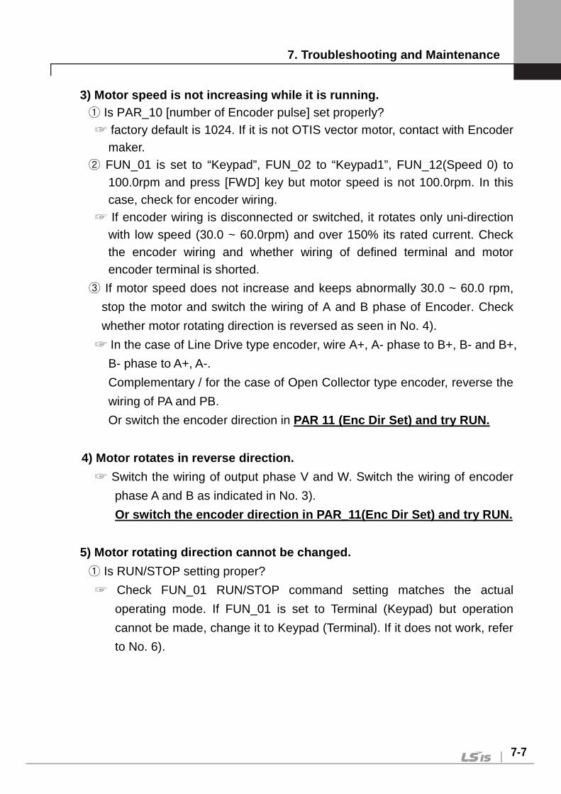
7. Troubleshooting and Maintenance
7-7
3) Motor speed is not increasing while it is runnin g. ① Is PAR_10 [number of Encoder pulse] set properly? factory default is 1024. If it is not OTIS vector motor, contact with Encoder
maker. ② FUN_01 is set to “Keypad”, FUN_02 to “Keypad1”, FUN_12(Speed 0) to
100.0rpm and press [FWD] key but motor speed is not 100.0rpm. In this case, check for encoder wiring.
If encoder wiring is disconnected or switched, it rotates only uni-direction with low speed (30.0 ~ 60.0rpm) and over 150% its rated current. Check the encoder wiring and whether wiring of defined terminal and motor encoder terminal is shorted.
③ If motor speed does not increase and keeps abnormally 30.0 ~ 60.0 rpm,
stop the motor and switch the wiring of A and B phase of Encoder. Check
whether motor rotating direction is reversed as seen in No. 4).
In the case of Line Drive type encoder, wire A+, A- phase to B+, B- and B+,
B- phase to A+, A-.
Complementary / for the case of Open Collector type encoder, reverse the
wiring of PA and PB.
Or switch the encoder direction in PAR 11 (Enc Dir Set) and try RUN.
4) Motor rotates in reverse direction.
Switch the wiring of output phase V and W. Switch the wiring of encoder
phase A and B as indicated in No. 3).
Or switch the encoder direction in PAR_11(Enc Dir S et) and try RUN.
5) Motor rotating direction cannot be changed.
① Is RUN/STOP setting proper?
Check FUN_01 RUN/STOP command setting matches the actual
operating mode. If FUN_01 is set to Terminal (Keypad) but operation
cannot be made, change it to Keypad (Terminal). If it does not work, refer
to No. 6).

7. Troubleshooting and Maintenance
7-8
② Is one of the terminal defined as FWD/REV Run Disable ON?
Check one of DIO_01 ~ DIO_07 terminals is defined as “Prohibit FWD” or
“Prohibit REV”. If so, check input terminal status in DIS_01 ~ DIS_03. If
rotating direction is not changed, check the terminal is ON.
6) Keypad or terminal malfunctions.
① When [REV], [FWD], [STOP] key on the keypad is lit Red or Green,
Refer to 1) if RUN/STOP is not activated by Keypad or Terminal. If setting
change is not available, PAR_04 may set to prohibit parameter write. To
release this setting, enter 12 in PAR_04. If problem persists, contact LS
representatives.
② When [STOP] key is blinking,
This marks trip condition or BX active status. Check any other trips occur
in DIS_05. Reset the trip and try run. Check BX signal is ON on the
keypad and input terminal signal in DIS_01 ~ DIS_03. Reset BX and try
run.
③ When green lamp on [REV], [FWD] key is blinking,
It marks accel/decel is in operation. If inverter keeps operation in this
condition, it means load capacity calculation is incorrect and exceeds
inverter rating. Refer to No. 16).
7) Operating speed does not change during run. ① Is FUN_02 speed setting proper?
Speed setting methods in STARVERT-iV5 are Analog input, Keypad and
Option. Select appropriate one among them.
② Is DIS_01(PreRamp Ref) setting the correct value?
Current speed ref. Values are displayed in DIS_01 ~ DIS_03. Check the
displayed value matches the setting value. If speed is not variable, check
the encoder. Refer to No. 13).
③ Speed setting method is “Keypad” and speed ref displayed DIS_01 ~
DIS_03 is not correct.
Check terminal setting in DIO_01 ~ DIO_07 defined as Multi-step speed
setting.
④ When speed setting method is Analog and DIS_01 ~ DIS_03 display is not

7. Troubleshooting and Maintenance
7-9
desired value,
Check one of Ai1 ~ Ai3 is defined as “Speed Ref.”.
8) Motor keeps rotating at OV condition when speed setting is via Analog
input. ① When AIO_11 Definition of Ai1 input is set to “Speed Ref”,
Adjust the Ai1_Bias at AIO_14. (Setting unit: %).
The displayed value is speed command. Set the desired value (ex : 0.0%)
and press [ENTER] key.
② Follow the same steps to check Ai2 ~ Ai3.
9) Motor detects speed reference but motor rpm is s howing decreasing while motor is overheated or hunting.
① Check the motor wiring.
There is a possibility of incorrect motor wiring when motor is 220V / 380V
dual rating. Motor does not normally rotate when pole number setting is
incorrect. However, motor may get damaged in case of miswiring. If this
problem occurs, contact motor sales office. Refer to Power terminal
description in this manual. ② Is motor capacity set correctly? Check PAR_07 motor rating selection is set the same as motor in use.
See the nameplate for motor rating. ③ Is motor parameter set correctly? Motor parameters vary by manufacturer. STARVERT-iV5 setting is based
on OTIS vector motor as default. Motor parameters should be changed when other makers’ motor is used.
10) Nothing displayed on the LCD?
① Is the connection of inverter and keypad tight? Check the inverter and Keypad connection. ② Is input power turned on? Check inverter power is applied. If nothing is displayed on the LCD in this
condition, contact LS representatives.

7. Troubleshooting and Maintenance
7-10
11) Motor speed oscillates and speed is not constan t during constant Run.
① Is encoder wired using twisted shield cable? encoder signal wiring should be conducted with Twisted Shield Cable.
Otherwise, speed may oscillate at low speed (or high speed) due to encoder input noise, leading to motor vibration or abnormal motor sound at stop.
② Is the connection of inverter and motor and encoder grounding proper? Check the grounding of inverter and encoder is connected. This could
occur when not connected. Fixed screw for the connection of encoder grounding and the inverter is located on the right bottom side of the control PCB. Loosen the fixed screw and insert the ground wire of the encoder and tighten the screw. (Refer to encoder wiring diagram). For grounding the motor, use G of the inverter Main terminal.
③ Connect inverter panel grounding connected with motor grounding to the building grounding. If not, incorrect motor speed may be input due to encoder input noise. ④ Is too large speed gain assigned to the inverter while motor load is light? Motor oscillates at stop when PI gain is set much larger than the actual
load in CON_03 and CON_04. Therefore, gain should be set accordingly. Responsiveness increases when P gain is set higher and I lower but system may become unstable. Gain value varies system but generally set 30 ~ 70% for P gain and set 100 ~ 500ms for I gain.
⑤ Increase PAR_13 Enc LPF setting value.
⑥ Is there slip present at the connection of encoder and motor shaft?
Poor encoder and motor connection may generate slip. Check the
connection is tight.
12) Parameter change is not saved.
Turn the power off and turn it on. If problem persists, contact LS
representatives.

7. Troubleshooting and Maintenance
7-11
13) “Fuse Open” trip occurs constantly.
① Is the input (line) voltage normal?
Check the line voltage input. If phase to phase unbalance exceeds
2%(greater than 6V for 380V input), an AC reactor should be provided.
Otherwise, inverter may get damaged and A/S fee will be charged during
Warranty period.
② Is the phase sequence of the output terminal U, V, W correct?
Check the level of the input signal.
③ Is the motor insulation damaged?
Various types of malfunction occur when the insulation is damaged. In
general, operation stops at a certain speed (and more), overload or “OC-
U (V, W)” trip occurs during regenerating. Or motor overheating and
rotating speed oscillates. This condition persists for a while and then
“Fuse Open” trip occurs. It marks motor insulation is damaged. In this
case, replace the motor.
14) Motor input current is too large. Check the motor wiring. ①
Check the motor wiring for the use of 220V / 380V transition type motor. (Refer to Main circuit terminal)
② Are motor and inverter capacity set correctly? ③ Is the setting of motor constants appropriate?
Refer to No. 2) and No. 9) and check the motor and inverter setting.
15) OC-U (V, W) trip occurs frequently during opera tion. (Motor input
current is oscillating.)
① Check the encoder installation.
If encoder connection is poor, motor vibration affects encoder and
incorrect encoder signal is input to the inverter. Vector inverter controls
the speed from Encoder F/B value so it follows the input signal whether
correct or not, increasing inverter current. If so, contact motor maker or
encoder commission company.
② Is there no inverter output phase loss?

7. Troubleshooting and Maintenance
7-12
③ Is the motor insulation not damaged?
Refer to No. 13) and check the inverter and motor.
16) Accel/Decel cannot be made properly and green l amp in [REV], [FWD]
key is blinking. (load and frequency reference sign al is oscillating.)
① Check motor wiring.
FUN_40 ~ FUN_47 Accel/Decel time and DIS_00 motor load. ②
Blinking Green lamp marks motor is accelerating or decelerating. If the
rotating speed oscillates and green lamp is blinking, it marks inverter
output torque shortage due to mis-calculation of load. In this case,
increase the torque limit to enable inverter to accelerate/decelerate
within its rating. If load is set too high, it will shorten inverter life or
damage to the unit.
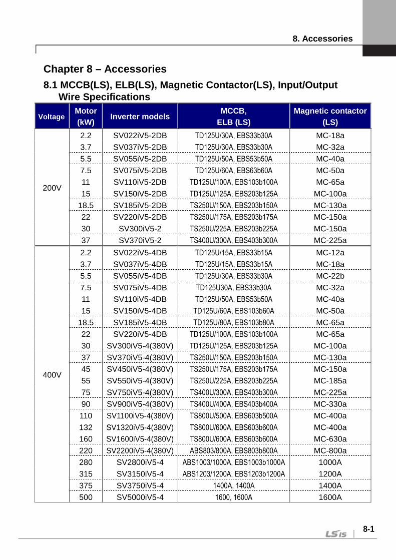
8. Accessories
8-1
Chapter 8 – Accessories 8.1 MCCB(LS), ELB(LS), Magnetic Contactor(LS), Inpu t/Output
Wire Specifications
Voltage Motor (kW)
Inverter models MCCB,
ELB (LS) Magnetic contactor
(LS)
200V
2.2 SV022iV5-2DB TD125U/30A, EBS33b30A MC-18a
3.7 SV037iV5-2DB TD125U/30A, EBS33b30A MC-32a
5.5 SV055iV5-2DB TD125U/50A, EBS53b50A MC-40a
7.5 SV075iV5-2DB TD125U/60A, EBS63b60A MC-50a
11 SV110iV5-2DB TD125U/100A, EBS103b100A MC-65a
15 SV150iV5-2DB TD125U/125A, EBS203b125A MC-100a
18.5 SV185iV5-2DB TS250U/150A, EBS203b150A MC-130a
22 SV220iV5-2DB TS250U/175A, EBS203b175A MC-150a
30 SV300iV5-2 TS250U/225A, EBS203b225A MC-150a
37 SV370iV5-2 TS400U/300A, EBS403b300A MC-225a
400V
2.2 SV022iV5-4DB TD125U/15A, EBS33b15A MC-12a
3.7 SV037iV5-4DB TD125U/15A, EBS33b15A MC-18a
5.5 SV055iV5-4DB TD125U/30A, EBS33b30A MC-22b
7.5 SV075iV5-4DB TD125U30A, EBS33b30A MC-32a
11 SV110iV5-4DB TD125U/50A, EBS53b50A MC-40a
15 SV150iV5-4DB TD125U/60A, EBS103b60A MC-50a
18.5 SV185iV5-4DB TD125U/80A, EBS103b80A MC-65a
22 SV220iV5-4DB TD125U/100A, EBS103b100A MC-65a
30 SV300iV5-4(380V) TD125U/125A, EBS203b125A MC-100a
37 SV370iV5-4(380V) TS250U/150A, EBS203b150A MC-130a
45 SV450iV5-4(380V) TS250U/175A, EBS203b175A MC-150a
55 SV550iV5-4(380V) TS250U/225A, EBS203b225A MC-185a
75 SV750iV5-4(380V) TS400U/300A, EBS403b300A MC-225a
90 SV900iV5-4(380V) TS400U/400A, EBS403b400A MC-330a
110 SV1100iV5-4(380V) TS800U/500A, EBS603b500A MC-400a
132 SV1320iV5-4(380V) TS800U/600A, EBS603b600A MC-400a
160 SV1600iV5-4(380V) TS800U/600A, EBS603b600A MC-630a
220 SV2200iV5-4(380V) ABS803/800A, EBS803b800A MC-800a
280 SV2800iV5-4 ABS1003/1000A, EBS1003b1000A 1000A
315 SV3150iV5-4 ABS1203/1200A, EBS1203b1200A 1200A
375 SV3750iV5-4 1400A, 1400A 1400A
500 SV5000iV5-4 1600, 1600A 1600A

8. Accessories
8-2
※※※※ Please refer to our LSIS MCCB, ELB and MC catalog for the your order. The product indicated with only current will be rel eased in the near future. 8.2 AC input fuse, AC reactor, DC reactor
Voltage Motor (kW)
Inverter models AC
input fuse
AC reactor DC reactor
200V
2.2 SV022iV5-2DB 25 A 0.88 mH, 14 A − 3.7 SV037iV5-2DB 40 A 0.56 mH, 20 A − 5.5 SV055iV5-2DB 40 A 0.39 mH, 30 A − 7.5 SV075iV5-2DB 50 A 0.28 mH, 40 A − 11 SV110iV5-2DB 70 A 0.20 mH, 59 A − 15 SV150iV5-2DB 100 A 0.15 mH, 75 A −
18.5 SV185iV5-2DB 100 A 0.12 mH, 96 A − 22 SV220iV5-2DB 125 A 0.10 mH, 112 A − 30 SV300iV5-2 150A 0.08 mH, 134 A 0.35 mH, 152 A 37 SV370iV5-2 200A 0.07 mH, 160 A 0.30 mH, 180 A
400V
2.2 SV022iV5-4DB 10 A 3.23 mH, 7.5 A − 3.7 SV037iV5-4DB 20 A 2.34 mH, 10 A − 5.5 SV055iV5-4DB 20 A 1.22 mH, 15 A − 7.5 SV075iV5-4DB 30 A 1.14 mH, 20 A − 11 SV110iV5-4DB 35 A 0.81 mH, 30 A − 15 SV150iV5-4DB 45 A 0.61 mH, 38 A −
18.5 SV185iV5-4DB 60 A 0.45 mH, 50 A − 22 SV220iV5-4DB 70 A 0.39 mH, 58 A − 30 SV300iV5-4(380V) 100 A 0.33 mH, 67 A 1.19 mH, 76 A 37 SV370iV5-4(380V) 100 A 0.27 mH, 82 A 0.98 mH, 93 A 45 SV450iV5-4(380V) 100 A 0.22 mH, 100 A 0.89 mH, 112 A 55 SV550iV5-4(380V) 150 A 0.15 mH, 121 A 0.75 mH, 135 A 75 SV750iV5-4(380V) 200 A 0.13 mH, 167 A 0.44 mH, 187 A 90 SV900iV5-4(380V) 250 A 0.11 mH, 201 A 0.35 mH, 225 A 110 SV1100iV5-4(380V) 300 A 0.09 mH, 245 A 0.30 mH, 274 A 132 SV1320iV5-4(380V) 400 A 0.08 mH, 290 A 0.26 mH, 324 A 160 SV1600iV5-4(380V) 400 A 0.06 mH, 357 A 0.22 mH, 399 A 220 SV2200iV5-4(380V) 800A 0.029mH, 799 A 0.1mH, 530 A 280 SV2800iV5-4 900A 0.029mH, 799 A 0.090mH, 836 A 315 SV3150iV5-4 1000A 0.024mH, 952 A 0.076mH, 996 A 375 SV3750iV5-4 1200A 0.024mH, 952 A 0.064mH, 1195 A 500 SV5000iV5-4 1600A 0.021mH, 1248A -
※ For 2.2~22kW, DC reactor standard is not provided, for not having DC reactor wiring terminal.
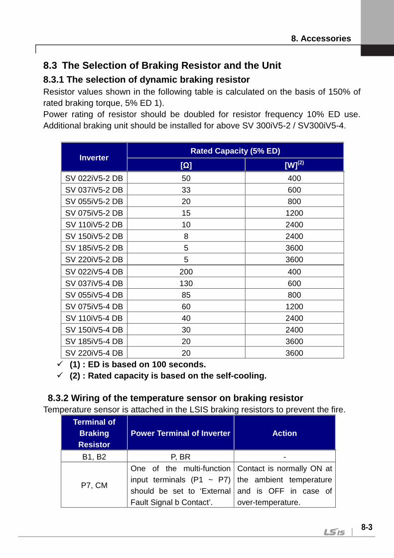
8. Accessories
8-3
8.3 The Selection of Braking Resistor and the Unit 8.3.1 The selection of dynamic braking resistor Resistor values shown in the following table is calculated on the basis of 150% of rated braking torque, 5% ED 1). Power rating of resistor should be doubled for resistor frequency 10% ED use. Additional braking unit should be installed for above SV 300iV5-2 / SV300iV5-4.
Inverter Rated Capacity (5% ED)
[ΩΩΩΩ] [W] (2)
SV 022iV5-2 DB 50 400
SV 037iV5-2 DB 33 600
SV 055iV5-2 DB 20 800
SV 075iV5-2 DB 15 1200
SV 110iV5-2 DB 10 2400
SV 150iV5-2 DB 8 2400
SV 185iV5-2 DB 5 3600
SV 220iV5-2 DB 5 3600
SV 022iV5-4 DB 200 400
SV 037iV5-4 DB 130 600
SV 055iV5-4 DB 85 800
SV 075iV5-4 DB 60 1200
SV 110iV5-4 DB 40 2400
SV 150iV5-4 DB 30 2400
SV 185iV5-4 DB 20 3600
SV 220iV5-4 DB 20 3600
(1) : ED is based on 100 seconds. (2) : Rated capacity is based on the self-cooling.
8.3.2 Wiring of the temperature sensor on braking r esistor
Temperature sensor is attached in the LSIS braking resistors to prevent the fire. Terminal of
Braking Resistor
Power Terminal of Inverter Action
B1, B2 P, BR -
P7, CM
One of the multi-function input terminals (P1 ~ P7) should be set to ‘External Fault Signal b Contact’.
Contact is normally ON at the ambient temperature and is OFF in case of over-temperature.

8. Accessories
8-4
8.3.3 Braking unit ① SV037DBH-2 : 37kW/200V Class Braking Unit (10% ED) ② SV037DBH-4 : 37kW/400V Class Braking Unit (10% ED) ③ SV075DBH-4 : 75kW/400V Class Braking Unit (10% ED) ④ SV075DB-4 : 75kW/400V Class Braking Unit (100% ED) ⑤ SV220DB-4 : 220kW/400V Class Braking Unit (100% ED)
- The Combination of two braking unit for 400V class is possible for more than SV900iV5-4 capacity.
- When ED is more than 10%, Use the braking unit for 100% ED (Ex: vertical load such as carne, hoist).
- When the inverter capacity is more than 220kW, use the braking unit for SV2200DB-4 (100% ED).
- Refer to description manual included in braking unit product for the use of 100% ED braking unit.
8.3.4 Combination of braking unit
SV[][][]
iV5-2 SV[][][][]iV5-4
300/370 300/370 450/550/750 900/1100/
1320/1600 2200
2800/3150/
3750
200V 37kW 1 - - - - -
400V
37kW - 1 - - - -
75kW - - 1 2 - -
220kW - - - - 1 2
Note)
1. Example) Combine two braking units of 75kW-400V Class for SV-900iV5-4(90kW) Class.
2. Refer to the Braking Unit user manual that came with the braking unit. 3. Please contact to LSIS customer service center about above 200kW.
Inverter
Braking
unit

8. Accessories
8-5
8.3.5 Braking resistor for braking unit
Braking Unit 100% of Braking Torque, 10% ED
Resistance [ ΩΩΩΩ] Rated Power [kW]
37kW-200V 3 5 37kW-400V 12 5 75kW-400V 6 10 75kW-400V 6 Refer to extra manual in the case of
100% ED braking unit. 220kW-400V 2
8. Accessories
8-6
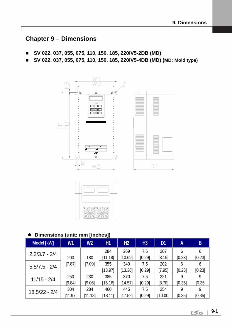
9. Dimensions
9-1
Chapter 9 – Dimensions SV 022, 037, 055, 075, 110, 150, 185, 220iV5-2DB (MD) SV 022, 037, 055, 075, 110, 150, 185, 220iV5-4DB (MD) (MD: Mold type)
Dimensions (unit: mm [inches])
Model [kW] W1 W2 H1 H2 H3 D1 A B
2.2/3.7 - 2/4 200
[7.87] 180
[7.09]
284 [11.18]
269 [10.69]
7.5 [0.29]
207 [8.15]
6 [0.23]
6 [0.23]
5.5/7.5 - 2/4 355 [13.97]
340 [13.38]
7.5 [0.29]
202 [7.95]
6 [0.23]
6 [0.23]
11/15 - 2/4 250 [9.84]
230 [9.06]
385 [15.16]
370 [14.57]
7.5 [0.29]
221 [8.70]
9 [0.35]
9 [0.35
18.5/22 - 2/4 304 [11.97]
284 [11.18]
460 [18.11]
445 [17.52]
7.5 [0.29]
254 [10.00]
9 [0.35]
9 [0.35]

9. Dimensions
9-2
SV055, 075, 110, 150, 185, 220iV5-2 DB SV055, 075, 110, 150, 185, 220iV5-4 DB SV055, 075, 110, 150, 185, 220iV5-4 DC (DC: DC powe r input type)
ECTOR
ONTROL
Dimensions (unit: mm [inches]) *DC has a same dimension as AC.
Model [kW] W1 W2 H1 H2 H3 D1 A B
5.5/7.5 - 2/4 234.4 [9.22]
180 [7.08]
406.2 [15.9]
391.2 [15.4]
7.5 [0.29]
221.1 [8.7]
6 [0.23]
6 [0.23]
11/15/18.5/22 - 2/4 335
[13.1] 284
[11.1] 526
[20.7] 509
[20.0] 10
[0.39] 248.6 [9.78]
9 [0.35]
9 [0.35]

9. Dimensions
9-3
SV300, 370iV5-2 SV300, 370, 450, 550, 750iV5-4 SV300, 370, 450, 550, 750iV5-4 DC (DC: DC power inp ut type)
Dimensions (unit: mm [inches]) *DC has a same dimension as AC.
Model [kW] W1 W2 H1 H2 H3 D1 A B
30/37 – 2/4 350
[13.7]] 270
[10.6] 680
[26.7] 660
[26.0] 12
[0.47] 308.2 [12.1]
10 [0.39]
10 [0.39]
45/55/75 - 4 375
[14.7] 275
[10.8] 780
[30.7] 758.5 [29.8]
11 [0.43]
326 [12.8]
11 [0.43]
11 [0.43]

9. Dimensions
9-4
SV900, 1100, 1320, 1600iV5-4 SV900, 1100, 1320, 1600iV5-4 (DC: DC power input ty pe)
Dimensions (unit : mm[inches]) *DC has a same dimension as AC .
Model [kW] W1 W2 H1 H2 H3 D1 A B
90/110 - 4 530
[20.8] 430
[16.9] 780
[30.7] 760
[29.9] 11.5
[0.45] 335
[13.2] 13
[0.51] 13
[0.51]
132/160 - 4 530
[20.8] 430
[16.9] 1000 [39.3]
980 [38.5]
11.5 [0.45]
345 [13.5]
13 [0.51]
13 [0.51]

9. Dimensions
9-5
SV2200iV5-4 SV2200iV5-4DC (DC: DC power input type)
STARVERT-iV5
Dimensions (unit : mm[inches]) *DC has a same dimension as AC.
Model [kW] W1 W2 H1 H2 H3 D1 A B
220 - 4 680
[26.77] 540
[21.26] 998
[39.29] 968.5 [38.13]
17.5 [0.68]
403 [15.87]
14 [0.55]
14 [0.55]
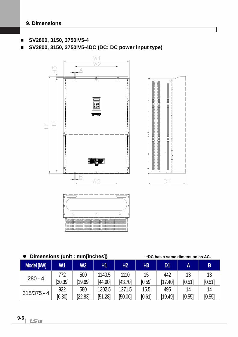
9. Dimensions
9-6
SV2800, 3150, 3750iV5-4 SV2800, 3150, 3750iV5-4DC (DC: DC power input type)
Dimensions (unit : mm[inches]) *DC has a same dimension as AC.
Model [kW] W1 W2 H1 H2 H3 D1 A B
280 - 4 772
[30.39] 500
[19.69] 1140.5 [44.90]
1110 [43.70]
15 [0.59]
442 [17.40]
13 [0.51]
13 [0.51]
315/375 - 4 922
[6.30] 580
[22.83] 1302.5 [51.28]
1271.5 [50.06]
15.5 [0.61]
495 [19.49]
14 [0.55]
14 [0.55]

9. Dimensions
9-7
SV5000iV5-4 SV5000iV5-4DC (DC: DC power input type)
Dimensions (unit : mm[inches]) *DC has a same dimension as AC.
Model [kW] W1 W2 W3 W4 H1 H2 H3 H4 D1 A B
500kW - 4 1200
(47.25) 1050
(41.34) 75
(2.95) 350
(13.78) 1330
(52.36) 1280
(50.39) 20
(0.79) 1225
(48.23) 550
(21.65) 26
(10.24) 13
(0.51)

ADDITIONAL UL MARKING
1. Short Circuit Rating “Suitable For Use On A Circuit Capable Of Delivering Not More Than Table1* RMS Symmetrical Amperes, 240 for rated 240V drives or 480 for rated 480V drives Volts Maximum,” or equivalent.
Table1* Inverter Capacity Rating
200/400V Class: 5.5kW, 7.5kW, 11kW, 15kW, 18.5 kW, 22kW, 30kW, 37kW 5,000A 400V Class: 45kW, 55kW, 75kW, 90kW, 110kW, 132kW 10,000A 400V Class: 160kW, 220kW 18,000A
2. SHORT CIRCUIT FUSE/BREAKER MARKING Use Class H or K5 UL Listed Input Fuse and UL Listed Breaker Only. See the table below for the Voltage and Current rating of the fuses and the breakers.
Input [V]
Inverter [kW]
External Fuse Breaker Internal Fuse Current
[A] Voltage
[V] Current
[A] Voltage
[V] Current
[A] Voltage [Vac/dc] Manufacturer Model
Number
200 Class
5.5 40 500 50 220 60 250
Hinode Elec
250GH-60 7.5 50 500 60 220 60 250 250GH-60 11 70 500 100 220 125 250 250GH-125 15 100 500 100 220 150 250 250GH-150
18.5 100 500 225 220 175 250 250GH-175 22 125 500 225 220 225 250 250GH-225 30 150 500 225 220 250 250 250GH-250S 37 200 500 225 220 250 250 250GH-250S
400 Class
5.5 20 500 30 460 35 660 660GH-35 7.5 30 500 30 460 35 660 660GH-35 11 35 500 50 460 63 660 660GH-63 15 45 500 60 460 80 660 660GH-80
18.5 60 500 100 460 100 660 660GH-100 22 70 500 100 460 125 660 660GH-125 30 100 500 100 460 125 600 600FH-125S 37 100 500 225 460 150 600 600FH-150S 45 100 500 225 460 200 600 600FH-200S 55 150 500 225 460 200 600 600FH-200S 75 200 500 225 460 125 600 600FH-125S 90 250 500 400 460 200 600 600FH-200S 110 300 500 400 460 200 600 600FH-200S 132 400 500 400 460 300 600 600FH-300S 160 400 500 400 460 300 600 600FH-300S 220 ― ― 600 460 600 600 600SPF-600UL
3. FIELD WIRING TERMINAL
1) Use Copper wires only with Copper conductors, 75 2) Input and motor output terminal blocks are intended only for use with ring
type connectors. 4. CAUTION-Risk of Electric Shock
“Before opening the cover, disconnect all power and wait at least 10 minutes” Units suitable only for use in a pollution degree 2 environment. Be sure to mount the inverter in a forced-ventilated operating panel.

EC DECLARATION OF CONFORMITY
We, the undersigned, Representative: LSIS Co., Ltd.
Address: LS Tower, 127, LS-ro, Dongan-gu, Anyang-si, Gyeonggi-do,
Korea Manufacturer: LSIS Co., Ltd. Address: 56, Samseong 4-gil, Mokcheon-eup, Dongnam-gu, Cheonan-si, Chungcheongnam-do, Korea Certify and declare under our sole responsibility that the following apparatus: Type of Equipment: Inverter (Power Conversion Equipment) Model Name: STARVERT-iV5 series Trade Mark: LSIS Co., Ltd.
Conforms with the essential requirements of the directives: 2014/35/EU Directive of the European Parliament and of the Council on the harmonisation of the laws of the Member States relating to the making available on the market of electrical equipment designed for use within certain voltage limits 2014/30/EU Directive of the European Parliament and of the Council on the harmonisation of the laws of the Member States relating to electromagnetic compatibility Based on the following specifications applied:
EN 61800-3:2004 EN 61800-5-1:2007
and therefore complies with the essential requirements and provisions of the 2014/35/CE and 2014/30/CE Directives. Place: Cheonan, Chungnam, Korea

EMI / RFI POWER LINE FILTERS LS inverters, iV5 series
CAUTION
THE LS RANGE OF POWER LINE FILTERS FF ( Footprint ) - FE ( Standard ) SERIES, HAVE BEEN SPECIFICALLY DESIGNED WITH HIGH FREQUENCY LG INVERTERS. THE USE OF LS FILTERS, WITH THE INSTALLATION ADVICE OVERLEAF HELP TO ENSURE TROUBLE FREE USE ALONG SIDE SENSITIVE DEVICES AND COMPLIANCE TO CONDUCTED EMISSION AND IMMUNITY STANDARS TO EN 50081.
RECOMMENDED INSTALLATION INSTRUCTIONS To conform to the EMC directive, it is necessary that these instructions be followed as closely as possible. Follow the usual safety procedures when working with electrical equipment. All electrical connections to the filter, inverter and motor must be made by a qualified electrical technician. 1- ) Check the filter rating label to ensure that the current, voltage rating and part number are correct. 2- ) For best results the filter should be fitted as closely as possible to the incoming mains supply of
the wiring enclousure, usually directly after the enclousures circuit breaker or supply switch. 3- ) The back panel of the wiring cabinet of board should be prepared for the mounting dimensions of
the filter. Care should be taken to remove any paint etc... from the mounting holes and face area of the panel to ensure the best possible earthing of the filter.
4- ) Mount the filter securely. 5- ) Connect the mains supply to the filter terminals marked LINE, connect any earth cables to the
earth stud provided. Connect the filter terminals marked LOAD to the mains input of the inverter using short lengths of appropriate gauge cable.
6- ) Connect the motor and fit the ferrite core ( output chokes ) as close to the inverter as possible.
Armoured or screened cable should be used with the 3 phase conductors only threaded twice through the center of the ferrite core. The earth conductor should be securely earthed at both inverter and motor ends. The screen should be connected to the enclousure body via and earthed cable gland.
7- ) Connect any control cables as instructed in the inverter instructions manual. IT IS IMPORTANT THAT ALL LEAD LENGHTS ARE KEPT AS SHORT AS POSSIBLE AND THAT INCOMING MAINS AND OUTGOING MOTOR CABLES ARE KEPT WELL SEPARATED.
RFI FILTERS
IN CASE OF A LEAKAGE CURRENT PROTECTIVE DEVICES IS USED ON POWER SUPPLY, IT MAY BE FAULT AT POWER-ON OR OFF. IN AVOID THIS CASE, THE SENSE CURRENT OF PROTECTIVE DEVICE SHOULD BE LARGER THAN VALUE OF LAKAGE CURRENT AT WORST CASE IN THE BELOW TABLE.

X (1) Industrial environment EN 50081-2 (A class) EN61000-6-4: 02 (2) Domestic and industrial environment EN50081-1 (B class) EN61000-6-3: 02
iV5 series / Footprint Filters
INVERTER POWER CODE CURRENT VOLTAGE LEAKAGE CURRENT
DIMENSIONS L W H
MOUNTING Y X WEIGHT MOUNT FIG OUTPUT
CHOKES THREE PHASE NOM. MAX.
SV022iV5-2 (DB) 2.2kW FFV5-T020-(x) 20A 250VAC 0.5mA 27mA 329x199.5x60 315x160 1.8Kg. M5 A FS-2
SV037iV5-2 (DB) 3.7kW SV055iV5-2 (DB) 5.5kW FFV5-T030-(x) 30A 250VAC 0.5mA 27mA 451x234.5x60 437x190 2.1Kg. M5 A FS-2 SV075iV5-2 (DB) 7.5kW FFV5-T050-(x) 50A 250VAC 0.5mA 27mA 451x234.5x60 437x190 2.6Kg. M5 A FS-2 SV110iV5-2 (DB) 11kW
- 100A 250VAC 0.5mA 27mA - - - - - - SV150iV5-2 (DB) 15kW SV185iV5-2 (DB) 18kW
- 120A 250VAC 0.5mA 27mA - - - - - - SV220iV5-2 (DB) 22kW SV300iV5-2 (DB) 30kW - 150A 250VAC 0.5mA 27mA - - - - - - SV370iV5-2 (DB) 37kW - 180A 250VAC 0.5mA 27mA - - - - - - SV022iV5-4 (DB) 2.2kW
FFV5-T011-(x) 11A 380VAC 0.5mA 27mA 329x199.5x60 315x160 1.5Kg. M5 A FS-2 SV037iV5-4 (DB) 3.7kW SV055iV5-4 (DB) 5.5kW
FFV5-T030-(x) 30A 380VAC 0.5mA 27mA 451x234.5x60 437x190 2Kg. M5 A FS-2 SV075iV5-4 (DB) 7.5kW SV110iV5-4 (DB) 11kW
FFV5-T051-(x) 51A 380VAC 0.5mA 27mA 605x335x65 579.5x265 2.5Kg. M8 A FS-2 SV150iV5-4 (DB) 15kW SV185iV5-4 (DB) 18kW FFV5-T060-(x) 60A 380VAC 0.5mA 27mA 605x335x65 579.5x265 2.8Kg. M8 A FS-2 SV220iV5-4 (DB) 22kW FFV5-T070-(x) 70A 380VAC 0.5mA 27mA 605x335x65 579.5x265 2.8Kg. M8 A FS-3 SV300iV5-4 (DB) 30kW FFV5-T071-(x) 71A 380VAC 0.5mA 27mA 756x350x65 730.5x281 3Kg. M8 A FS-3 SV370iV5-4 (DB) 37kW - 100A 380VAC 0.5mA 27mA - - - - - - SV450iV5-4 (DB) 45kW
- 120A 380VAC 0.5mA 27mA - - - - - - SV550iV5-4 (DB) 55kW SV750iV5-4 (DB) 75kW - 170A 380VAC 0.5mA 27mA - - - - - - SV900iV5-4 (DB) 90kW - 230A 380VAC 0.5mA 27mA - - - - - - SV1100iV5-4 (DB) 110kW
- 400A 380VAC 0.5mA 27mA - - - - - - SV1320iV5-4 (DB) 132kW SV1600iV5-4 (DB) 160kW
- 600A 380VAC 0.5mA 27mA - - - - - - SV2200iV5-4 (DB) 220kW SV2800iV5-4 (DB) 280kW
- 1000A 380VAC 0.5mA 27mA - - - - - - SV3150iV5-4 (DB) 315kW SV3750iV5-4 (DB) 375kW
SV055iV5-2DB (MD) 5.5kW FFV5-T031-(x) 31A 250VAC 0.5mA 27mA 400x199.5x60 386x160 2Kg. M5 A FS-2 SV075iV5-2DB (MD) 7.5kW FFV5-T052-(x) 52A 250VAC 0.5mA 27mA 400x199.5x60 386x160 2.5Kg. M5 A FS-2 SV110iV5-2DB (MD) 11kW
- 100A 250VAC 0.5mA 27mA - - - - A FS-2 SV150iV5-2DB (MD) 15kW SV185iV5-2DB (MD) 18kW
- 120A 250VAC 0.5mA 27mA - - - - A FS-2 SV220iV5-2DB (MD) 22kW SV055iV5-4DB (MD) 5.5kW
FFV5-T031-(x) 31A 380VAC 0.5mA 27mA 400x199.5x60 386x160 2Kg. M5 A FS-2 SV075iV5-4DB (MD) 7.5kW SV110iV5-4DB (MD) 11kW
FFV5-T053-(x) 53A 380VAC 0.5mA 27mA 466x258x65 440.5x181 2.5Kg. M5 A FS-2 SV150iV5-4DB (MD) 15kW SV185iV5-4DB (MD) 18kW FFV5-T061-(x) 61A 380VAC 0.5mA 27mA 541x312x65 515.5x235 2.6Kg. M8 A FS-2 SV220iV5-4DB (MD) 22kW FFV5-T072-(x) 72A 380VAC 0.5mA 27mA 541x312x65 515.5x235 2.8Kg. M8 A FS-3

iV5 series / Standard Filters
INVERTER POWER CODE CURRENT VOLTAGE LEAKAGE CURRENT
DIMENSIONS L W H
MOUNTING Y X WEIGHT MOUNT FIG. OUTPUT
CHOKES
THREE PHASE NOM. MAX.
SV022iV5-2 (DB) 2.2kW FE-T020-(x) 20A 250VAC 0.5mA 27mA 270x140x60 258x106 2.2Kg. --- B FS-2
SV037iV5-2 (DB) 3.7kW SV055iV5-2 (DB) 5.5kW FE-T030-(x) 30A 250VAC 0.5mA 27mA 270x140x60 258x106 2.4Kg. --- B FS-2 SV075iV5-2 (DB) 7.5kW FE-T050-(x) 50A 250VAC 0.5mA 27mA 270x140x90 258x106 3.2Kg. --- B FS-2 SV110iV5-2 (DB) 11kW
FE-T100-(x) 100A 250VAC 0.5mA 27mA 425x200x130 408x166 13.8Kg. --- B FS-3 SV150iV5-2 (DB) 15kW SV185iV5-2 (DB) 18kW
FE-T120-(x) 120A 250VAC 0.5mA 27mA 425x200x130 408x166 13.8Kg. --- B FS-3 SV220iV5-2 (DB) 22kW SV300iV5-2 (DB) 30kW FE-T150-(x) 150A 250VAC 0.5mA 27mA 480x200x160 468x166 15Kg. --- B FS-3 SV370iV5-2 (DB) 37kW FE-T170-(x) 170A 250VAC 0.5mA 27mA 480x200x160 468x166 16Kg. --- B FS-3 SV022iV5-4 (DB) 2.2kW FE-T012-(x) 12A 380VAC 0.5mA 27mA 250x110x60 238x76 1.6Kg. --- B FS-2 SV037iV5-4 (DB) 3.7kW SV055iV5-4 (DB) 5.5kW
FE-T030-(x) 30A 380VAC 0.5mA 27mA 270x140x60 258x106 2.4Kg. --- B FS-2 SV075iV5-4 (DB) 7.5kW SV110iV5-4 (DB) 11kW
FE-T050-(x) 50A 380VAC 0.5mA 27mA 270x140x90 258x106 3.2Kg. --- B FS-2 SV150iV5-4 (DB) 15kW SV185iV5-4 (DB) 18kW FE-T060-(x) 60A 380VAC 0.5mA 27mA 270x140x90 258x106 3.5Kg. --- B FS-2 SV220iV5-4 (DB) 22kW
FE-T070-(x) 70A 380VAC 0.5mA 27mA 350x180x90 338x146 7.5Kg. --- B FS-3 SV300iV5-4 (DB) 30kW SV370iV5-4 (DB) 37kW FE-T100-(x) 100A 380VAC 1.3mA 150mA 425x200x130 408x166 13.8Kg. --- B FS-3 SV450iV5-4 (DB) 45kW
FE-T120-(x) 120A 380VAC 1.3mA 150mA 425x200x130 408x166 13.8Kg. --- B FS-3 SV550iV5-4 (DB) 55kW SV750iV5-4 (DB) 75kW FE-T170-(x) 170A 380VAC 1.3mA 150mA 480x200x160 468x166 16Kg. --- B FS-3 SV900iV5-4 (DB) 90kW FE-T230-(x) 230A 380VAC 1.3mA 150mA 580x250x205 560x170 22.6Kg. --- B FS-4 SV1100iV5-4 (DB) 110kW
FE-T400-(x) 400A 380VAC 1.3mA 150mA 392x260x116 240x235 10.3Kg. --- C FS-4 SV1320iV5-4 (DB) 132kW SV1600iV5-4 (DB) 160kW
FE-T600-(x) 600A 380VAC 1.3mA 150mA 392x260x116 240x235 10.3Kg. --- C FS-4 SV2200iV5-4 (DB) 220kW SV2800iV5-4 (DB) 280kW
FE-T1000-(x) 1000A 380VAC 1.3mA 150mA 460x280x166 290x255 18Kg. --- C FS-4 SV3150iV5-4 (DB) 315kW
SV3750iV5-4 (DB) 375kW SV055iV5-2DB (MD) 5.5kW FE-T030-(x) 30A 250VAC 0.5mA 27mA 270x140x60 258x106 2.4Kg. --- B FS-2 SV075iV5-2DB (MD) 7.5kW FE-T050-(x) 50A 250VAC 0.5mA 27mA 270x140x90 258x106 3.2Kg. --- B FS-2 SV110iV5-2DB (MD) 11kW
FE-T100-(x) 100A 250VAC 0.5mA 27mA 425x200x130 408x166 13.8Kg. --- B FS-3 SV150iV5-2DB (MD) 15kW SV185iV5-2DB (MD) 18kW
FE-T120-(x) 120A 250VAC 0.5mA 27mA 425x200x130 408x166 13.8Kg. --- B FS-3 SV220iV5-2DB (MD) 22kW SV055iV5-4DB (MD) 5.5kW
FE-T030-(x) 30A 380VAC 0.5mA 27mA 270x140x60 258x106 2.4Kg. --- B FS-2 SV075iV5-4DB (MD) 7.5kW SV110iV5-4DB (MD) 11kW
FE-T050-(x) 50A 380VAC 0.5mA 27mA 270x140x90 258x106 3.2Kg. --- B FS-2 SV150iV5-4DB (MD) 15kW SV185iV5-4DB (MD) 18kW FE-T060-(x) 60A 380VAC 0.5mA 27mA 270x140x90 258x106 3.5Kg. --- B FS-2 SV220iV5-4DB (MD) 22kW FE-T070-(x) 70A 380VAC 0.5mA 27mA 350x180x90 338x146 7.5Kg. --- B FS-3
X (1) Industrial environment EN 50081-2 (A class) EN61000-6-4 :02
(2) Domestic and industrial environment EN50081-1 (B class) EN61000-6-3 :02


UL mark
The UL mark applies to products in the United States and Canada. This mark indicates that UL has tested and
evaluated the products and determined that the products satisfy the UL standards for product safety. If a
product received UL certification, this means that all components inside the product had been certified for UL
standards as well.
Suitable for Installation in a Compartment Handing Conditioned Air
CE mark
The CE mark indicates that the products carrying this mark comply with European safety and environmental
regulations. European standards include the Machinery Directive for machine manufacturers, the Low Voltage
Directive for electronics manufacturers and the EMC guidelines for safe noise control.
Low Voltage Directive
We have confirmed that our products comply with the Low Voltage Directive (EN 61800-5-1).
EMC Directive
The Directive defines the requirements for immunity and emissions of electrical equipment used within the
European Union. The EMC product standard (EN 61800-3) covers requirements stated for drives.
EAC mark
The EAC (EurAsian Conformity) mark is applied to the products before they are placed on the market of
the Eurasian Customs Union member states.
It indicates the compliance of the products with the following technical regulations and requirements of
the Eurasian Customs Union:
Technical Regulations of the Customs Union 004/2011 “On safety of low voltage equipment”
Technical Regulations of the Customs Union 020/2011 “On electromagnetic compatibility of technical products”

Warranty
Maker LSIS Co., Ltd. Installation
(Start-up) Date
Model No. SV-iV5 New Controller Warranty
Period
Customer Information
Name Address
Tel.
Sales Office (Distributor)
Name
Address Tel.
This product has been manufactured through a strict quality management and inspection process by LS Technical Team. The warranty period is 18 months from the date manufactured, provided that, the warranty period is subject change depending on the terms and condition of the agreement under separate cover.
FOC Service
If there is any failure in the product during the afore-mentioned warranty period you can have it repaired FOC by requesting our distributor or designated service center subject that you are found to have used it under our recommended environment. For further details, please refer to out company's regulation.
Charged Service
In the event of any of the following cases, the service will be charged.
- The failure occurred from the consumer's improper storage, handling, and careless handling
- The failure occurred from the consumer's error in the design of software or hardward
- The failure occurred from the error of power source and the defect of the connector
- The failure occurred from the force majeure (fire, flood, gas disaster, earthquake, etc.)
- The product was modified or repaired at the discretion of the consumer in the place other than our Distributor or the Service Center.
- The name plate provided by LS is not attached on the product
- The product was used in an improper way or beyond the operating range.
Repair Warranty Period for the Discontinued Model
- For the product discontinued, the repair service will be provided with charge for five years from the date discontinued.
Waiver of the warranty for the mechanical loss, etc.
LSIS Co., Ltd. doesn't bear any responsibility to indemnify indirect, special, incidental, or consequential loss (including the indemnification of sales loss, loss profit, etc.

Revision History
No. Date Edition Changes
1 July, 2011 First Release New controller ver. 3.00 released
2 April, 2013 2 nd Edition Ver. 3.20 / Short floor operation, Profibus data Swap function added
LSIS regards the environmental preservation as a high priority, and all our employees do our best for the environmental preservation fresh earth.
LS inverter is designed for preserving environment.
When you disuse the products, you can recycle by separating them to iron, aluminum, bronze, and synthetic plastic (cover).
Environment management Disposable product
