safety instructions iwaki pneumatic drive bellows pump ... · pump structure & operating...
TRANSCRIPT

©2011 IWAKI CO., LTD.
Thank you for choosing our product.
Please read through this instruction manual before use.
This instruction manual describes important precautions and instruc-
tions for the product. Always keep it on hand for quick reference.
Instruction manual
FS-100HT2
Iwakipneumatic drive bellows pump
Safe
ty in
stru
ctio
ns
Overv
iew
Insta
llatio
nO
pera
tion
Main
ten
an
ce
Specification
2
Order confirmation
Open the package and check that the product conforms to your order. If any problem or
inconsistency is found, immediately contact your distributor.
a. Check if the delivery is correct.
Check the nameplate to see if the information such as model codes are as ordered.
* Electrical wiring changes with the controllers.
b. Check if the required number of accessories is provided.
<Attached accessories>
A FDC-1 controller and two QEV-15V quick exhaust valves
c. Check if the delivery is damaged or deformed.
Check for transit damage and loose bolts.
Order confirmation
3Contents
Contents
Order confirmation ..........................................................................................................................................2
Safety instructions .................................................................... 5
Warning ..........................................................................................................................................................6
Caution ...........................................................................................................................................................7
Precautions for use ......................................................................................................................................9
Overview ...................................................................................10
Introduction ................................................................................................................................................. 10
Pump structure & Operating principle ...................................................................................................... 10
Part names ................................................................................................................................................... 11
Pump ........................................................................................................................................................ 11
Operating conditions .................................................................................................................................. 12
Pump stroke ............................................................................................................................................. 12
Supply air pressure range ........................................................................................................................ 12
Liquid temperature range ......................................................................................................................... 12
Liquid characteristics ............................................................................................................................... 12
Do not run the pump with the following liquid ..................................................................................... 12
Use care handling the following liquids: .............................................................................................. 12
Operation and Stoppage .......................................................................................................................... 13
During operation ................................................................................................................................. 13
When stopping the pump .................................................................................................................... 13
During stoppage .................................................................................................................................. 13
Air exhaust port ........................................................................................................................................ 13
Leak sensor .............................................................................................................................................. 13
Ambient temperature ................................................................................................................................ 13
Pump surface temperature....................................................................................................................... 13
Noise from pump ...................................................................................................................................... 13
Identification codes .................................................................................................................................... 14
Installation ...............................................................................15
Pump mounting ........................................................................................................................................... 15
Liquid line piping ........................................................................................................................................ 17
Suction line ............................................................................................................................................... 18
Flooded suction ................................................................................................................................... 18
Filtration (suction line end) .................................................................................................................. 18
When installing a valve on the suction line: ........................................................................................ 18
4 Contents
Discharge line .......................................................................................................................................... 19
Pulsation reduction ............................................................................................................................. 19
When installing a valve on the discharge line: .................................................................................... 19
Filtration (circulation) ........................................................................................................................... 19
Filtration (discharge line end) .............................................................................................................. 19
Depressurization at pump stop ........................................................................................................... 19
Degassing ................................................................................................................................................20
Air line piping .............................................................................................................................................. 21
Supply air port I.D. .............................................................................................................................. 21
Air line piping diagram ..............................................................................................................................22
Composite effective cross-sectional area ................................................................................................ 24
Effective cross-sectional area ............................................................................................................. 24
Preventive measures against condensation ....................................................................................... 24
Electric wiring .............................................................................................................................................25
Installation ................................................................................................................................................25
Lead wires ........................................................................................................................................... 25
Extension of leak sensor wires ...........................................................................................................25
Installation of proximity switch wires ................................................................................................... 25
Extension of proximity switch wires ....................................................................................................25
Wiring diagram .........................................................................................................................................26
Operation ................................................................................. 27
Before operation .........................................................................................................................................27
Pump operation ...........................................................................................................................................28
Starting the pump .....................................................................................................................................28
Flow rate adjustment ................................................................................................................................29
Stoppage ..................................................................................................................................................29
Maintenance ............................................................................ 30
Troubleshooting ..........................................................................................................................................30
Inspection ....................................................................................................................................................33
Daily inspection ........................................................................................................................................33
Periodic inspection ...................................................................................................................................33
Wear part list ............................................................................................................................................34
Specification/Outer dimension ..................................................................................................................35
Specification .............................................................................................................................................35
Pump ...................................................................................................................................................35
Outer dimension .......................................................................................................................................35
FS-100HT2 ..........................................................................................................................................35
Part names ...............................................................................................................................................36
FS-100HT2 ..........................................................................................................................................36
5
Safe
ty in
stru
ctio
ns
Safety instructions
Read through this section before use. This section describes important
information for you to prevent personal injury or property damage.
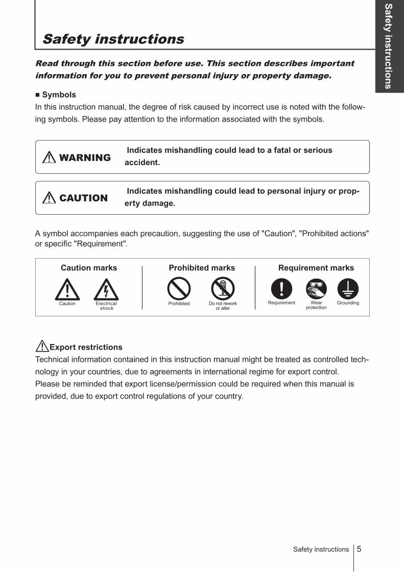
Symbols
In this instruction manual, the degree of risk caused by incorrect use is noted with the follow-
ing symbols. Please pay attention to the information associated with the symbols.
Indicates mishandling could lead to a fatal or serious
accident.WARNING
A symbol accompanies each precaution, suggesting the use of "Caution", "Prohibited actions"
or specific "Requirement".
Indicates mishandling could lead to personal injury or prop-
erty damage.CAUTION
Caution marks Prohibited marks Requirement marks
Safety instructions
ProhibitedElectrical
shock
Caution Do not rework
or alter
Requirement Wearprotection
Export restrictions
Technical information contained in this instruction manual might be treated as controlled tech-
nology in your countries, due to agreements in international regime for export control.
Please be reminded that export license/permission could be required when this manual is
provided, due to export control regulations of your country.
Grounding
6
WARNING
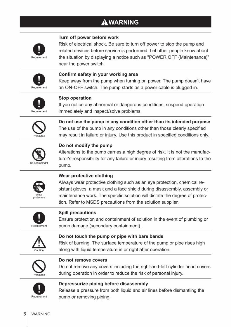
WARNING
Turn off power before work
Risk of electrical shock. Be sure to turn off power to stop the pump and
related devices before service is performed. Let other people know about
the situation by displaying a notice such as "POWER OFF (Maintenance)"
near the power switch.
Confirm safety in your working area
Keep away from the pump when turning on power. The pump doesn't have
an ON-OFF switch. The pump starts as a power cable is plugged in.
Stop operation
If you notice any abnormal or dangerous conditions, suspend operation
immediately and inspect/solve problems.
Do not use the pump in any condition other than its intended purpose
The use of the pump in any conditions other than those clearly specified
may result in failure or injury. Use this product in specified conditions only.
Do not modify the pump
Alterations to the pump carries a high degree of risk. It is not the manufac-
turer's responsibility for any failure or injury resulting from alterations to the
pump.
Wear protective clothing
Always wear protective clothing such as an eye protection, chemical re-
sistant gloves, a mask and a face shield during disassembly, assembly or
maintenance work. The specific solution will dictate the degree of protec-
tion. Refer to MSDS precautions from the solution supplier.
Spill precautions
Ensure protection and containment of solution in the event of plumbing or
pump damage (secondary containment).
Do not touch the pump or pipe with bare bands
Risk of burning. The surface temperature of the pump or pipe rises high
along with liquid temperature in or right after operation.
Do not remove covers
Do not remove any covers including the right-and-left cylinder head covers
during operation in order to reduce the risk of personal injury.
Depressurize piping before disassembly
Release a pressure from both liquid and air lines before dismantling the
pump or removing piping.
Requirement
Do not remodel
Wearprotectors
Requirement
Requirement
Requirement
Caution
Requirement
Prohibited
Prohibited

7
Safe
ty in
stru
ctio
ns
CAUTION
Qualified personnel only
The pump should be handled or operated by qualified personnel with a
full understanding of the pump. Any person not familiar with the product
should not take part in the operation or maintenance of the pump.
Use specified power only
Do not apply any power other than that specified on the nameplate. Other-
wise, failure or fire may result. Ensure the pump is properly grounded.
Ventilation
Fumes or vapours can be hazardous with certain solutions. Ensure proper
ventilation at the operation site.
Do not install or store the pump:
• In a flammable atmosphere.
• In a dusty/humid environment.
• In a corrosive atmosphere.
Do not stand on the pump
Do not use the pump as a platform. Injury or damage may result when the
pump turns over.
Flushing before operation
Flush the inside of the pump and piping with pure water or the liquid to be
delivered before the start of operation.
Do not run the pump with the following liquid:
• Liquid that easily crystallizes
• Slurry
• Low conductivity hydrocarbon liquid
Use care handling the following liquid:
• Stripper (the pump must be in explosion proof.)
• Solvent
• Hydrazine
• Fuming sulfuric acid
Static electricity
When low electric conductivity liquids such as ultra-pure water and fluor
inactive liquid (e.g. FluorinertTM) are handled, the static electricity may be
generated in the pump and may cause static discharge. Take counter-
measures to remove the static electricity.
CAUTION
Requirement
Requirement
Requirement
Requirement
Requirement
Prohibited
Prohibited
Prohibited
Requirement
8
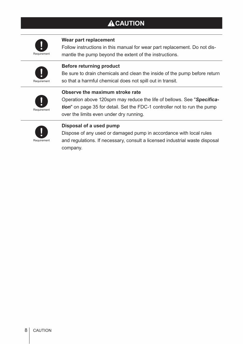
CAUTION
Wear part replacement
Follow instructions in this manual for wear part replacement. Do not dis-
mantle the pump beyond the extent of the instructions.
Before returning product
Be sure to drain chemicals and clean the inside of the pump before return
so that a harmful chemical does not spill out in transit.
Observe the maximum stroke rate
Operation above 120spm may reduce the life of bellows. See "Specifica-
tion" on page 35 for detail. Set the FDC-1 controller not to run the pump
over the limits even under dry running.
Disposal of a used pump
Dispose of any used or damaged pump in accordance with local rules
and regulations. If necessary, consult a licensed industrial waste disposal
company.
Requirement
Requirement
Requirement
Requirement
CAUTION

9
Safe
ty in
stru
ctio
ns
Precautions for use
Precautions for use
• During transit:
–Do not hit/wet the package.
–Do not place the package lateral/up side down.
– Keep the package dry.
– Do not stack the package on top of another.
• Electrical work should be performed by a qualified electrician. Otherwise,
personal injury or property damage could result.
• Do not install the pump:
–In a flammable atmosphere.
–In a dusty/humid place.
– In a corrosive atmosphere.
• Allow sufficient space around the pump for easy access and maintenance.
• Use care handling the pump. Do not drop. An impact may affect pump
performance. Do not use a pump that has been damaged to avoid the risk
of electrical damage or shock.
• The pump and controller are not waterproof. Do not operate the pump and
controller while wet with solution or water. Failure or injury may result. Im-
mediately dry off the pump and controller if they get wet.
• Do not close discharge line during operation. Solution may leak or piping
may break.
• Solution in the discharge line may be under pressure. Release the pres-
sure from the discharge line before disconnecting plumbing or disassembly
of the pump to avoid solution spray.
• Wear protective clothing when handling or working with pumps. Consult
solution MSDS for appropriate precautions. Do not come into contact with
residual solution.
• Do not leave the pump with any chemical in the bellows for a long period.
Some chemical gas can penetrate the bellows and corrode metal parts.
Run the pump for ten minutes a day for replacing gas when the pump is
going to be suspended two or three days.
Caution
Caution
Caution
Caution
Caution
Caution
Requirement
Requirement
Caution

10
Overview
Introduction
Pump characteristics, features and part names are described in this sec-
tion.
Introduction
Pump structure & Operating principle
An Iwaki FS-100HT2 pneumatic drive bellows pump has fluoric wet ends and is designed for semiconductor
manufacturing processes.
Principle of operation
The pump unit has two air chambers and a pair of bellows. The reciprocating motion of the bellows in the air
chambers introduces/delivers solution.
Suction process
Either bellows takes in solution via the inlet as it expands.
Discharge process
The bellows lets out solution via the inlet as it contracts.
: Liquid flow
: Supply air
Air OUT
Air chamber
Pump head
Air IN
BellowsOUT
IN
OUT
IN
Air IN Air OUT

11
Overv
iew
Part names
Part names
Pump
*Do not clean the pump or nameplate with a solvent such as benzine or thinner.
*Two or more personnel must be required to lift and move this pump.
Spec label
Stud boltHold the pump by the lower
stud bolts to lift it up.
Inlet
Outlet
Proximity switch cable port
OUT label
BaseAlways anchor the pump through the base.
Leak sensor cable port
Supply air port
IN label

12 Operating conditions
Operating conditions
Pump stroke
Observe the maximum stroke rate of 120spm, or the pump can take in a large amount of air, resulting dry run-
ning.
* Use the FDC-1 controller and set the maximum allowable speed.
Supply air pressure range
Observe the allowable supply air pressure range at each liquid temperature below.
Liquid temperature Supply air pressure
10-100ºC 0.15-0.5MPa
101-140ºC 0.15-0.4MPa
141-180ºC 0.15-0.3MPa
* Try to use the minimum allowable supply air pressure to protect the filter and bellows and reduce the risk of solution
spray.
* A flow rate changes with supply air pressure. Use a regulator to keep the pressure constant.
Liquid temperature range
Observe the allowable liquid temperature range of 10-180ºC. Note sharp temperature fluctuation (heat shock)
may reduce the life of the pump. Contact us for detail.
Liquid characteristics
Do not run the pump with the following liquid
• Liquid that easily crystallizes
• Slurry
• Low conductivity hydrocarbon liquid
* Crystallization or the delivery of slurry remarkably shorten the lives of valves and bellows.
* Delivery of low conductivity hydrocarbon liquid can cause ESD damage.
Use care handling the following liquid:
• Stripper
• Solvent
• Hydrazine
• Fuming sulfuric acid
* Some strippers cause cracks on the PFA bellows and piping, and therefore a warranty period is shortened. Contact us for
detail.
* An explosion-proof construction is required for the delivery of solvents. Contact us for detail.
13
Overv
iew
Operating conditions
Operation and Stoppage
During operation
Make sure a suction and a discharge line are fully opened.
When stopping the pump
• Before stopping the pump, release discharge line pressure. Otherwise, the bellows may deform.
• Do not close a discharge valve as stopping the pump, or an impact pressure may deform the bellows or con-
necting plate.
During stoppage
• Do not pressurize both the right and left air chambers at the same time, or the bellows may deform.
• Always check the specification of the double solenoid valve before installation. Some types (pressure centre
types) are designed to pressurize both the right and left air chambers at the same time.
• Do not leave the pump with any chemical in the bellows for a long period. Some chemical gas can penetrate
the bellows and corrode metal parts.
Air exhaust port
Do not narrow an air exhaust line (for example by reducing the tube I.D.). Or the residual pressure in the pump
may deform the bellows.
* Always observe the minimum composite effective cross-sectional area. Do not extend the air exhaust port too far away
from the solenoid valve (SV) or the quick exhaust valve (QEV). Otherwise, increased pipe resistance may break the limit.
Leak sensors
The sensors occasionally fails to detect leakage depending on operating conditions. Contact us for detail.
Ambient temperature
Observe the allowable operating ambient temperature range of 10-60ºC.
Pump surface temperature
Risk of burning. The surface temperature of the pump or pipe rises high along with liquid temperature in or
right after operation. e.g. cylinder surface temperature rises up to 80ºC when liquid temperature is 180ºC and
ambient temperature is 60ºC.
Noise from pump
Exhaust noise accompanies pump operation. Provide noise insulation as necessary. e.g. a noise level rises up
to 79.5dB (A) at 120spm and 0.5MPa (supply air pressure).
* The noise level above includes the operating noise from the pump and the SV.
14 Identification codes
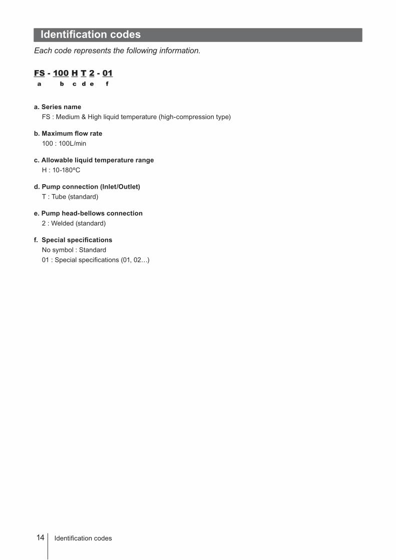
Identification codes
Each code represents the following information.
FS - 100 H T 2 - 01
a b c d e f
a. Series name
FS : Medium & High liquid temperature (high-compression type)
b. Maximum flow rate
100 : 100L/min
c. Allowable liquid temperature range
H : 10-180ºC
d. Pump connection (Inlet/Outlet)
T : Tube (standard)
e. Pump head-bellows connection
2 : Welded (standard)
f. Special specifications
No symbol : Standard
01 : Special specifications (01, 02…)
15
Insta
llatio
n
Installation
Pump mounting
Flooded
suction
*
Suction lift
This section describes the installation of the pump, piping and wiring. Read through
this section before work. To operate this pump, a 5-port solenoid valve and FDC-1
controller is needed. Always install QEVs (quick exhaust valves) to secure system
safety. Purchase separately.
Points to be observed
Observe the following points when installing the pump.
• Be sure to turn off power to stop the pump and related devices before service is per-
formed.
• Be careful for the power not to be turned on during work.
• If you notice any abnormal or dangerous conditions, suspend operation immediately and
inspect/solve problems.
• Do not install the pump in a flammable atmosphere.
Pump mounting
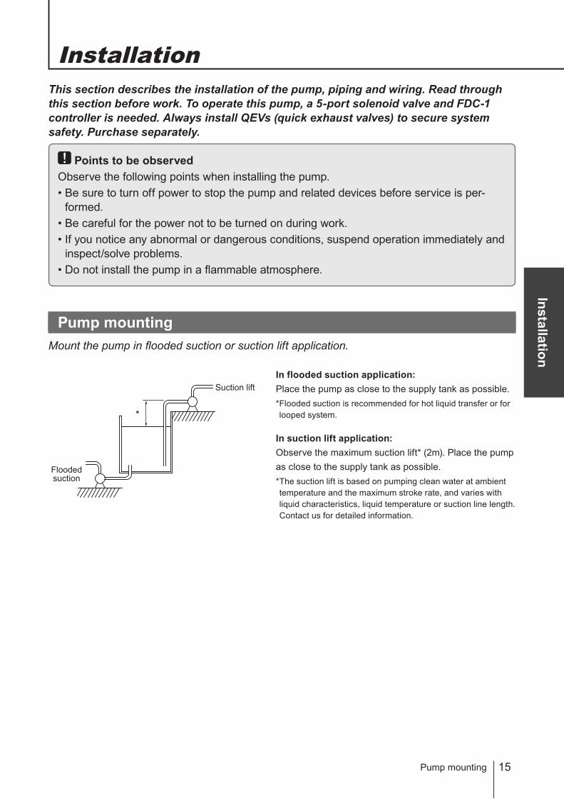
Mount the pump in flooded suction or suction lift application.
In flooded suction application:
Place the pump as close to the supply tank as possible.
* Flooded suction is recommended for hot liquid transfer or for
looped system.
In suction lift application:
Observe the maximum suction lift* (2m). Place the pump
as close to the supply tank as possible.
* The suction lift is based on pumping clean water at ambient
temperature and the maximum stroke rate, and varies with
liquid characteristics, liquid temperature or suction line length.
Contact us for detailed information.
16 Pump mounting
Select a location
Select a level location, free from vibration, that won't hold liquid. Anchor the pump so it doesn't vibrate.
See page 9 as well.
* Flooded suction application is recommended.
* Ovserve the maximum suction lift (1m) in suction lift application.
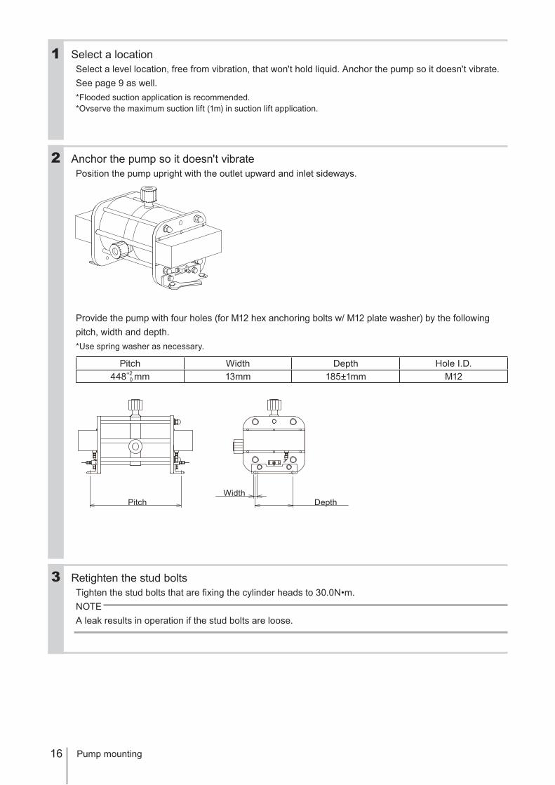
Anchor the pump so it doesn't vibrate
Position the pump upright with the outlet upward and inlet sideways.
Provide the pump with four holes (for M12 hex anchoring bolts w/ M12 plate washer) by the following
pitch, width and depth.
* Use spring washer as necessary.
Pitch Width Depth Hole I.D.
448+2
0 mm 13mm 185±1mm M12
Retighten the stud bolts
Tighten the stud bolts that are fixing the cylinder heads to 30.0N•m.
NOTE
A leak results in operation if the stud bolts are loose.
2
1
3
PitchWidth
Depth
17
Insta
llatio
n
Liquid line piping
Liquid line piping
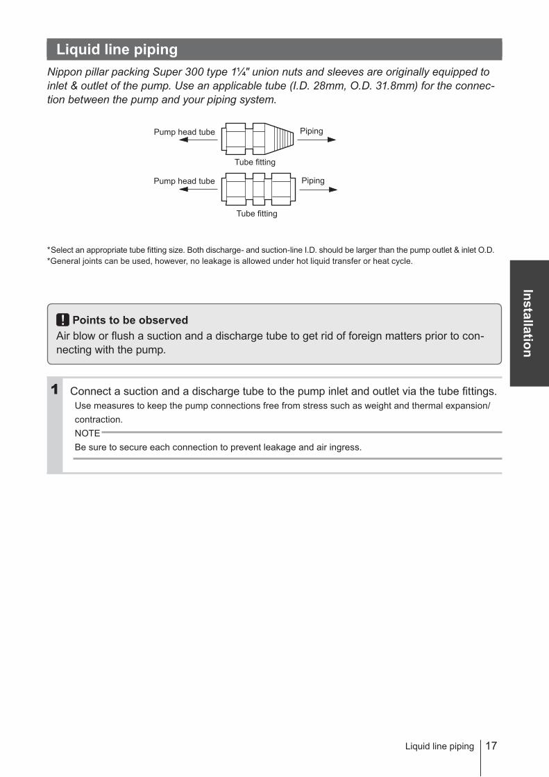
Nippon pillar packing Super 300 type 1¼" union nuts and sleeves are originally equipped to
inlet & outlet of the pump. Use an applicable tube (I.D. 28mm, O.D. 31.8mm) for the connec-
tion between the pump and your piping system.
* Select an appropriate tube fitting size. Both discharge- and suction-line I.D. should be larger than the pump outlet & inlet O.D.
* General joints can be used, however, no leakage is allowed under hot liquid transfer or heat cycle.
Points to be observed
Air blow or flush a suction and a discharge tube to get rid of foreign matters prior to con-
necting with the pump.
Connect a suction and a discharge tube to the pump inlet and outlet via the tube fittings.
Use measures to keep the pump connections free from stress such as weight and thermal expansion/
contraction.
NOTE
Be sure to secure each connection to prevent leakage and air ingress.
Pump head tube
Pump head tube
Tube fitting
Tube fitting
Piping
Piping
1
18
Suction line
Flooded suction
Have the suction line wide and shortest in flooded suction application. In suction lift application, observe the
maximum suction lift.
* The suction lift differs with the liquid’s characteristics, temperature and suction line length. For detailed information, con-
tact us.
Filtration (suction line end)
Install a filter or strainer at the suction line end to prevent particles from entering the bellows. The filter or
strainer should not increase piping resistance too much (observe the minimum composite effective cross-sec-
tional diameter.).
NOTE
If wafer fragments enter the pump, they may get stuck in the bellows and eventually cause failure. If they clog
the pump head valves, the discharge volume may reduce and the pumping operation may become unbal-
anced.
When installing a valve on the suction line:
Select a valve with an orifice equal to or larger than pipe I.D. A valve with a small orifice may increase the pipe
resistance or easily be clogged with crystals. Always open valves during operation.
NOTE
Operating the pump with a suction side valve close, negative pressure increases in the bellows and deforms
the bellows inwardly.
Liquid line piping
19
Insta
llatio
n
Liquid line piping
Discharge line
Pulsation reduction
The pipe resistance increases as a discharge line becomes longer or the number of bends increases. In
order to decrease pipe resistance, install a dampener and minimizes pulsation.
* When sending a liquid up via a riser pipe, install a check valve as well as a dampener.
When installing a valve on the discharge line:
Select a valve with an orifice equal to or larger than pipe I.D. A valve with a small orifice may increase the pipe
resistance or easily be clogged with crystals. Always open valves during operation. Do not close the valve until
the discharge pressure reaches "0" after the pump is stopped.
NOTE
Do not close a discharge valve right after stopping the pump. Impact pressure may deform the bellows.
Filtration (circulation)
Check a filtering area, filtering performance and effects on the flow before selecting a cycle filter. A desired
flow may not be obtained if selection is wrong.
NOTE
Wet the filter before use. A desired flow may not be obtained if the filter is dry. Filter dries up if it is unused for a
long period. Read the instruction manual of the filter for details.
Filtration (discharge line end)
Install a filter or strainer in a discharge line not to release foreign matters or wafer fragments. The filter or
strainer should not increase piping resistance too much (observe the minimum composite effective cross-sec-
tional diameter.).
Depressurization at pump stop
When stopping the pump, be sure to release discharge pressure by opening the filter, the air vent valve or
through a return circuit.
NOTE
Stopping the pump without releasing discharge pressure may deform the bellows.

20
Degassing
Gas bubbles are generated when a strong acid is fed into the reaction tank or liquid is transferred through a
narrow tube. If such bubbles enter the bellows, the pump runs dry, increasing stroke rate or disturbing liquid
transfer. Take a proper step for degassing.
Plan A (Install a baffle to remove gas bubbles)
In flooded suction application
Install a baffle in a overflow tank to separate air
from the liquid.
In suction lift application
Install a baffle to the bottom of the reaction tank.
And then place the end of suction line under the baf-
fle to suck liquid only.
Plan B (Install an automatic valve)
Periodic degassing
Program an automatic valve to open periodically
regardless of dry running. For example, the valve
opens for ten seconds every two minutes.
* Some filtering area may be too small to release air.
Select a suitable filter size.
* Program an open time according to the system perform-
ance.
Pinpoint degassing
Install an air detector at the pump inlet and set the
auto valve to open timely.
Another detector at the pump outlet will help detect
bellows rupture.
Bubbles go up.
Baffle
Overflowtank
P
Reaction tank
Reaction
tank Bubbles are
sucked.
Baffle
Prevents bubbles.
P P
H2O2,O3,H2O
Air vent line
Auto valve
Filter
PumpOverflow tank
Heater
Reaction tank
P
Liquid line piping
21
Insta
llatio
n
Air line piping
Points to be observed
Observe the following points when building up a supply air line.
• A fluctuation of supply air pressure affects the stroke rate and the flow rate. Install a
regulator to maintain the supply air pressure constant.
• Install a safety valve to observe the maximum supply air pressure at each liquid temper-
ature range. 0.5MPa at 10-100°C, 0.4MPa at 101-140°C and 0.3MPa at 141-180°C.
• Release the exhaust air into the open air. Narrowing the air exhaust port makes air less
likely to be expelled. As a result the bellows may deform inwardly. Select necessary air
devices with reference to the air line piping diagram on page 22.
• To reduce exhaust noise, release the exhaust air through the duct of the plant facility to
the air, or attach silencers to exhaust ports.
• The air consumption increases as installing two or more pumps and the number of
pumps increases. Optimise the air compressor capacity and air line I.D. taking account
of composite effective cross-sectional area.
• Supply air should be free from moisture and dust. If the supply air is contaminated with
water, oil or dust, the pump may fail in starting. If liquid enters the air chambers, the
electrodes may detect it and sounds an alarm.
• Long, narrow or bent supply air tubing prevents air from being expelled from the air
chamber, deforming the bellows inwardly, or stroke rate from increasing, reducing a
liquid flow.
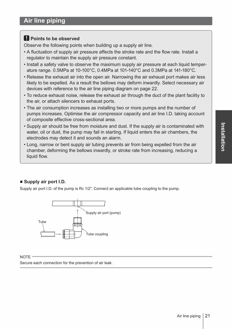
Supply air port I.D.
Supply air port I.D. of the pump is Rc 1/2". Connect an applicable tube coupling to the pump.
NOTE
Secure each connection for the prevention of air leak.
Air line piping
Tube
Supply air port (pump)
Tube coupling
22 Air line piping
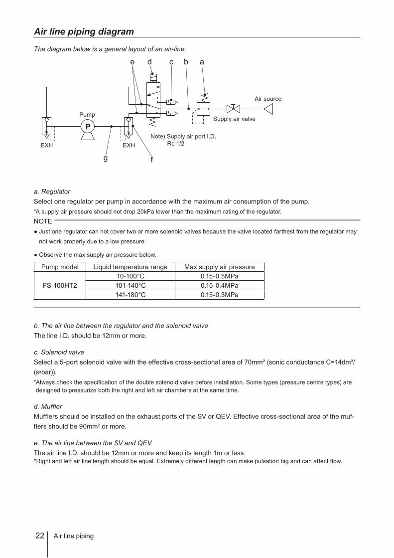
Air line piping diagram
The diagram below is a general layout of an air-line.
a. Regulator
Select one regulator per pump in accordance with the maximum air consumption of the pump.
* A supply air pressure should not drop 20kPa lower than the maximum rating of the regulator.
NOTE
Just one regulator can not cover two or more solenoid valves because the valve located farthest from the regulator may
not work properly due to a low pressure.
Observe the max supply air pressure below.
Pump model Liquid temperature range Max supply air pressure
FS-100HT2
10-100°C 0.15-0.5MPa
101-140°C 0.15-0.4MPa
141-180°C 0.15-0.3MPa
b. The air line between the regulator and the solenoid valve
The line I.D. should be 12mm or more.
c. Solenoid valve
Select a 5-port solenoid valve with the effective cross-sectional area of 70mm² (sonic conductance C=14dm³/
(s•bar)).
* Always check the specification of the double solenoid valve before installation. Some types (pressure centre types) are
designed to pressurize both the right and left air chambers at the same time.
d. Muffler
Mufflers should be installed on the exhaust ports of the SV or QEV. Effective cross-sectional area of the muf-
flers should be 90mm2 or more.
e. The air line between the SV and QEV
The air line I.D. should be 12mm or more and keep its length 1m or less.
* Right and left air line length should be equal. Extremely different length can make pulsation big and can affect flow.
P
Pump
EXH EXH
Note) Supply air port I.D.
Rc 1/2
Air source
a
g f
e d c b
Supply air valve
23
Insta
llatio
n
Air line piping
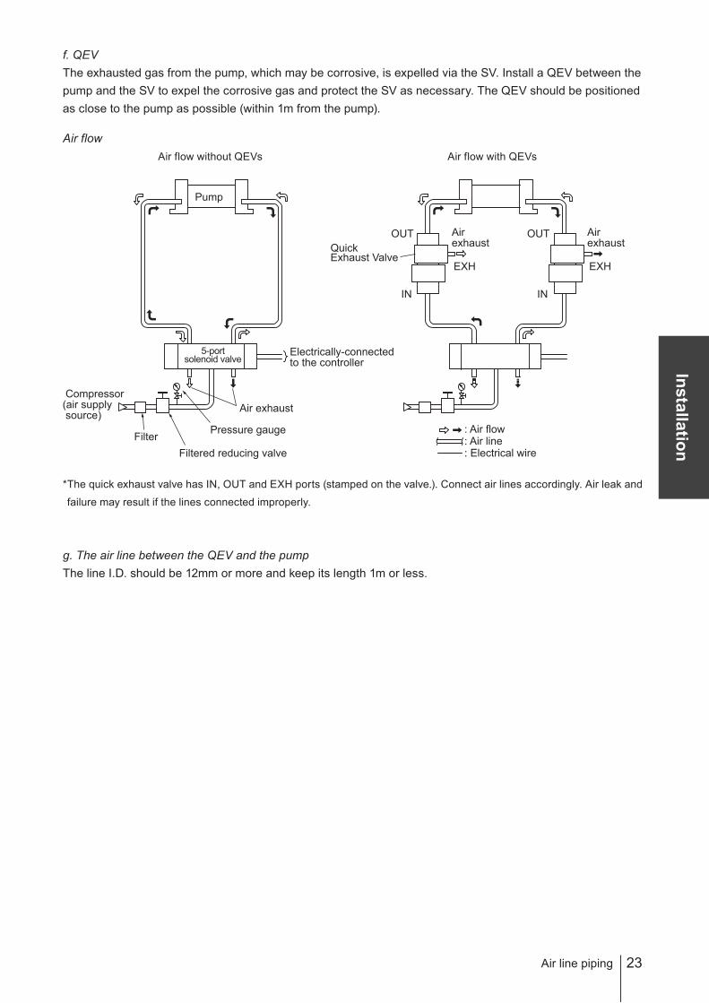
f. QEV
The exhausted gas from the pump, which may be corrosive, is expelled via the SV. Install a QEV between the
pump and the SV to expel the corrosive gas and protect the SV as necessary. The QEV should be positioned
as close to the pump as possible (within 1m from the pump).
Air flow
Air flow without QEVs Air flow with QEVs
* The quick exhaust valve has IN, OUT and EXH ports (stamped on the valve.). Connect air lines accordingly. Air leak and
failure may result if the lines connected improperly.
g. The air line between the QEV and the pump
The line I.D. should be 12mm or more and keep its length 1m or less.
Pump
5-port solenoid valve
Electrically-connectedto the controller
Air exhaust
Filtered reducing valve
Filter
Compressor (air supply source)
Pressure gauge
Air exhaust
EXH
Air exhaust
EXH
OUT
IN
OUT
IN
QuickExhaust Valve
: Air flow : Air line : Electrical wire
24
Composite effective cross-sectional area
Effective cross-sectional area
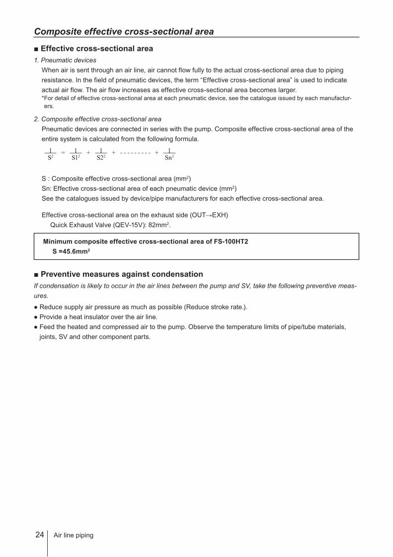
1. Pneumatic devices
When air is sent through an air line, air cannot flow fully to the actual cross-sectional area due to piping
resistance. In the field of pneumatic devices, the term “Effective cross-sectional area” is used to indicate
actual air flow. The air flow increases as effective cross-sectional area becomes larger.
* For detail of effective cross-sectional area at each pneumatic device, see the catalogue issued by each manufactur-
ers.
2. Composite effective cross-sectional area
Pneumatic devices are connected in series with the pump. Composite effective cross-sectional area of the
entire system is calculated from the following formula.
S : Composite effective cross-sectional area (mm2)
Sn: Effective cross-sectional area of each pneumatic device (mm2)
See the catalogues issued by device/pipe manufacturers for each effective cross-sectional area.
Effective cross-sectional area on the exhaust side (OUT→EXH)
Quick Exhaust Valve (QEV-15V): 82mm2.
Minimum composite effective cross-sectional area of FS-100HT2
S =45.6mm2
Preventive measures against condensation
If condensation is likely to occur in the air lines between the pump and SV, take the following preventive meas-
ures.
Reduce supply air pressure as much as possible (Reduce stroke rate.).
Provide a heat insulator over the air line.
Feed the heated and compressed air to the pump. Observe the temperature limits of pipe/tube materials,
joints, SV and other component parts.
S21 =
S121 +
S221 +
Sn21+
Air line piping

25
Insta
llatio
n
Electric wiring
Two 5-port double solenoid valves and the FDC-1 controller is required.
Points to be observed
Observe the following points during wiring work.
• Electrical work should be performed by a qualified electrician. Always observe applica-
ble codes or regulations.
• Do not perform wiring work while the power is on. Otherwise, an electrical shock or
short circuit may result. Be sure to turn off power before wiring work.
• Standard proximity switches can not be used when a flammable liquid such as solvent is
pumped. The proximity switches must be in explosion-proof specifications. Contact us or
your nearest dealer.
• Standard electrodes can not be used when a flammable liquid such as solvent is
pumped. A spark in a solvent may cause a fire.
Installation
Lead wires
5m proximity switch lead wires and 5m leak sensor lead wires are originally built in the pump but then other
lead wires for the connection between the controller and pneumatic devices are not provided. Purchase sepa-
rately.
Lead wires Required spec
FDC-1 controller power lead 115V 0.24A or more
Connection between the 5-port SV and the FDC-1 controller 24V 0.24A or more
Extension of leak sensor wires
Always keep resistance 5kΩ or less. Otherwise, the leak sensor does not work properly.
Installation of proximity switch wires
Do not lay on these wires in parallel with the power lead or combine them in a concentric cable (ex. 5 wires
cable). Otherwise, system malfunction may result.
Extension of proximity switch wires
When extending a proximity switch wire, select the following cable spec depending on cable length.
Wire length Wire spec
Shorter than 30m 0.3mm² or more
30m or longer 100Ω/km or less (conductor resistance)
Electric wiring
26 Electric wiring
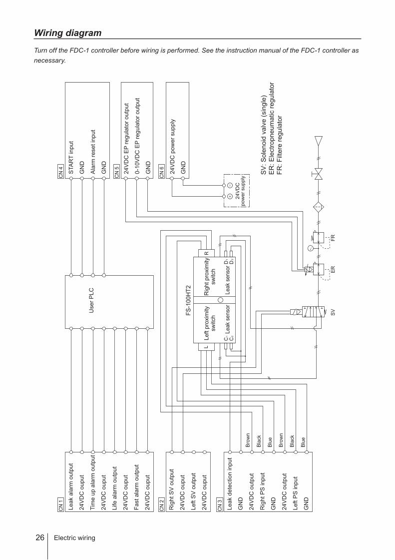
Wiring diagram
Turn off the FDC-1 controller before wiring is performed. See the instruction manual of the FDC-1 controller as
necessary.C
N 1
CN
4
CN
5
CN
3
Leak d
ete
ction input
GN
D
24V
DC
outp
ut
Rig
ht
PS
input
GN
D
24V
DC
outp
ut
Left
PS
input
GN
D
CN
2
Rig
ht
SV
outp
ut
24V
DC
ouput
Left
SV
outp
ut
24V
DC
ouput
CN
6
24V
DC
pow
er
supply
SV
: S
ole
noid
valv
e (
sin
gle
)
ER
: E
lectr
opneum
atic r
egula
tor
FR
: F
iltere
regula
tor
C1
C2
D1
D2
RL
←
Bro
wn
Bla
ck
Blu
e
Bro
wn
Bla
ck
Blu
e
FS
-100H
T2
SV
ER
FR
Left p
roxim
ity
sw
itch
Rig
ht pro
xim
ity
sw
itch
Leak
senso
rLeak
senso
r
STA
RT
input
GN
D
Ala
rm r
eset
input
GN
D
User
PLC
Leak a
larm
outp
ut
24V
DC
ouput
Tim
e u
p a
larm
outp
ut
24V
DC
ouput
Life a
larm
outp
ut
24V
DC
ouput
Fast
ala
rm o
utp
ut
24V
DC
ouput
24V
DC
pow
er
supply
GN
D
24V
DC
EP
regula
tor
outp
ut
0-1
0V
DC
EP
regula
tor
outp
ut
GN
D

27
Op
era
tion
Before operation
This section describes pump operation and programming. Run the pump
after pipework and wiring is completed.
Before operation
Always check the following items before the first-time operation or resuming operation after a
long period of stoppage.
Check if electric wiring is made correctly.
Check the wiring of proximity switches, leak sensors, solenoid valves, and electropneumatic regulators.
NOTE
A proximity switch may break. Always ensure correct wiring.
Check if air piping is made correctly.
Check if the pump is anchored securely.
Check if liquid piping is made correctly.
Check if a suction and a discharge line is open.
Check for a liquid level in the supply tank.
Check if the filter is wet.
NOTE
See manufacturer's manual for detail.
Operation
2
1
3
4
5
6
7

28 Pump operation
Pump operation
The start/stop of the pump is controlled by the FDC-1 controller in MANU mode or a user
PLC in AUTO mode. The procedure below is the example of starting the pump by keypad
operation with the FDC-1.
Points to be observed
Before operation in your system, conduct a trial run with pure water (or chemical liquid) to
flush out particles or to measure metal ion level.
Starting the pump
Supply air to the pump and open supply air lines.
Set the regulator to keep the allowable range of supply air pressure below.
Pump model Liquid temperature range Allowable supply air pressure range
FS-100HT2
10-100°C 0.15-0.5MPa
101-140°C 0.15-0.4MPa
141-180°C 0.15-0.3MPa
NOTE
Set an opening of an air valve in order for the pump not to run over the maximum stroke rate under dry
running.
Push the ENTER key, and then use the SELECT key to choose the option of "START".
Push the ENTER key, and then use the SELECT key to choose the option of "FLOW1" or
"FLOW2".
Push the ENTER key.
The pump starts to run with a flashing blue LED on the controller.
2
1
4
3
29
Op
era
tion
Pump operation
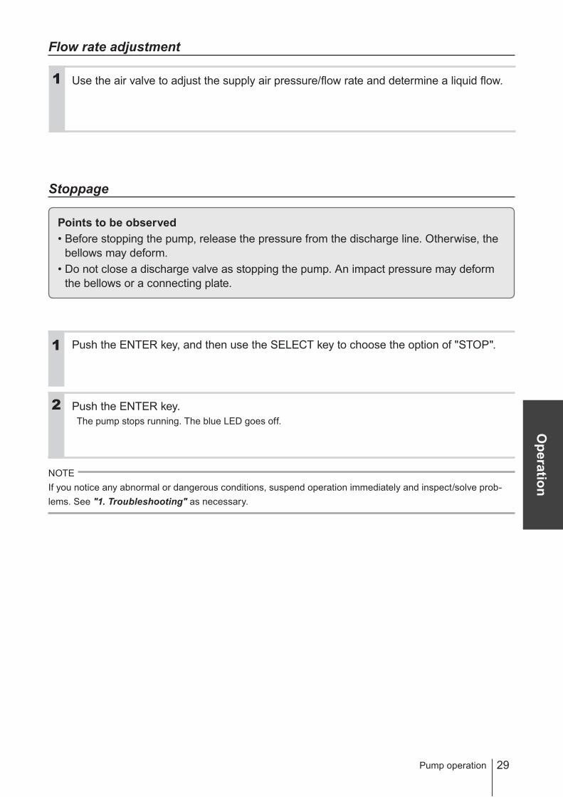
Flow rate adjustment
Use the air valve to adjust the supply air pressure/flow rate and determine a liquid flow.
Stoppage
Points to be observed
• Before stopping the pump, release the pressure from the discharge line. Otherwise, the
bellows may deform.
• Do not close a discharge valve as stopping the pump. An impact pressure may deform
the bellows or a connecting plate.
Push the ENTER key, and then use the SELECT key to choose the option of "STOP".
Push the ENTER key.
The pump stops running. The blue LED goes off.
NOTE
If you notice any abnormal or dangerous conditions, suspend operation immediately and inspect/solve prob-
lems. See "1. Troubleshooting" as necessary.
2
1
1
30 Troubleshooting
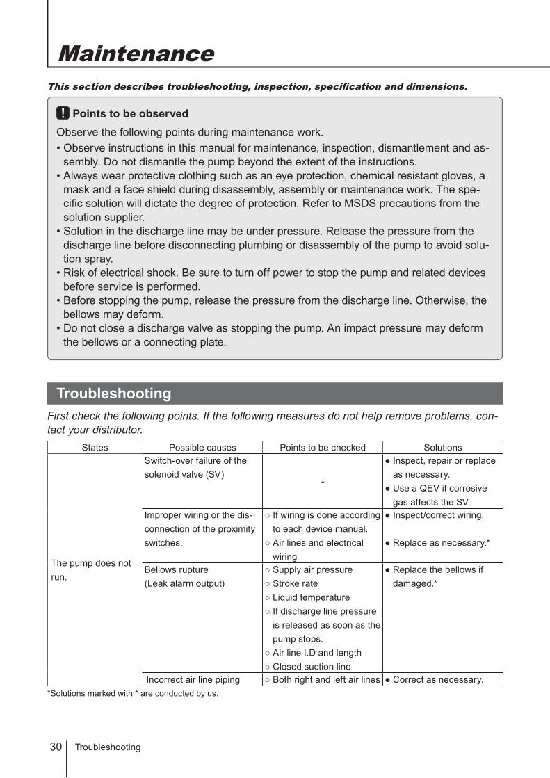
This section describes troubleshooting, inspection, specification and dimensions.
Points to be observed
Observe the following points during maintenance work.
• Observe instructions in this manual for maintenance, inspection, dismantlement and as-
sembly. Do not dismantle the pump beyond the extent of the instructions.
• Always wear protective clothing such as an eye protection, chemical resistant gloves, a
mask and a face shield during disassembly, assembly or maintenance work. The spe-
cific solution will dictate the degree of protection. Refer to MSDS precautions from the
solution supplier.
• Solution in the discharge line may be under pressure. Release the pressure from the
discharge line before disconnecting plumbing or disassembly of the pump to avoid solu-
tion spray.
• Risk of electrical shock. Be sure to turn off power to stop the pump and related devices
before service is performed.
• Before stopping the pump, release the pressure from the discharge line. Otherwise, the
bellows may deform.
• Do not close a discharge valve as stopping the pump. An impact pressure may deform
the bellows or a connecting plate.
Troubleshooting
First check the following points. If the following measures do not help remove problems, con-
tact your distributor.
States Possible causes Points to be checked Solutions
The pump does not
run.
Switch-over failure of the
solenoid valve (SV)-
Inspect, repair or replace
as necessary.
Use a QEV if corrosive
gas affects the SV.
Improper wiring or the dis-
connection of the proximity
switches.
If wiring is done according
to each device manual.
Air lines and electrical
wiring
Inspect/correct wiring.
Replace as necessary.*
Bellows rupture
(Leak alarm output)
Supply air pressure
Stroke rate
Liquid temperature
If discharge line pressure
is released as soon as the
pump stops.
Air line I.D and length
Closed suction line
Replace the bellows if
damaged.*
Incorrect air line piping Both right and left air lines Correct as necessary.
* Solutions marked with * are conducted by us.
Maintenance
31
Main
ten
an
ce
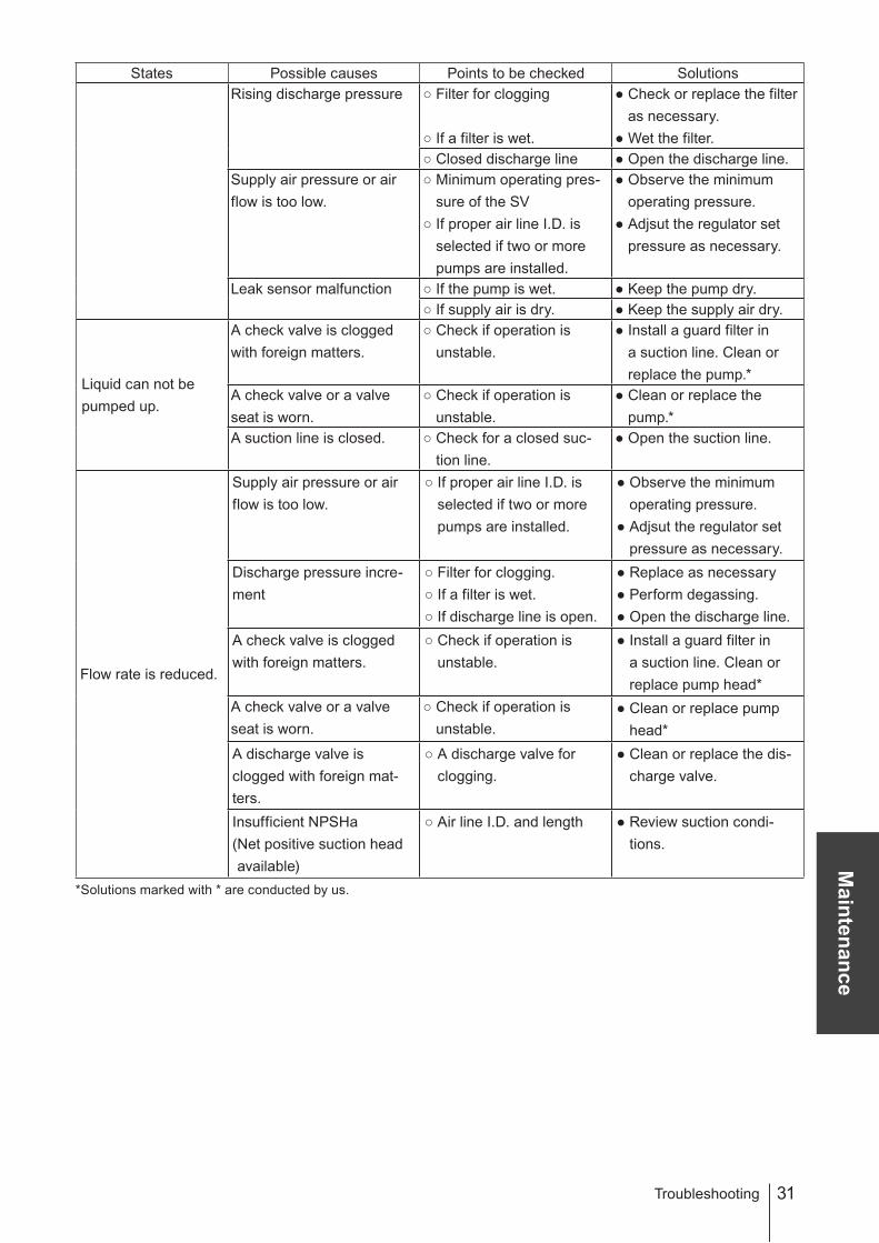
Troubleshooting
States Possible causes Points to be checked Solutions
Rising discharge pressure Filter for clogging
If a filter is wet.
Check or replace the filter
as necessary.
Wet the filter.
Closed discharge line Open the discharge line.
Supply air pressure or air
flow is too low.
Minimum operating pres-
sure of the SV
If proper air line I.D. is
selected if two or more
pumps are installed.
Observe the minimum
operating pressure.
Adjsut the regulator set
pressure as necessary.
Leak sensor malfunction If the pump is wet. Keep the pump dry.
If supply air is dry. Keep the supply air dry.
Liquid can not be
pumped up.
A check valve is clogged
with foreign matters.
Check if operation is
unstable.
Install a guard filter in
a suction line. Clean or
replace the pump.*
A check valve or a valve
seat is worn.
Check if operation is
unstable.
Clean or replace the
pump.*
A suction line is closed. Check for a closed suc-
tion line.
Open the suction line.
Flow rate is reduced.
Supply air pressure or air
flow is too low.
If proper air line I.D. is
selected if two or more
pumps are installed.
Observe the minimum
operating pressure.
Adjsut the regulator set
pressure as necessary.
Discharge pressure incre-
ment
Filter for clogging.
If a filter is wet.
If discharge line is open.
Replace as necessary
Perform degassing.
Open the discharge line.
A check valve is clogged
with foreign matters.
Check if operation is
unstable.
Install a guard filter in
a suction line. Clean or
replace pump head*
A check valve or a valve
seat is worn.
Check if operation is
unstable.
Clean or replace pump
head*
A discharge valve is
clogged with foreign mat-
ters.
A discharge valve for
clogging.
Clean or replace the dis-
charge valve.
Insufficient NPSHa
( Net positive suction head
available)
Air line I.D. and length Review suction condi-
tions.
* Solutions marked with * are conducted by us.

32
States Possible causes Points to be checked Solutions
Liquid leaks.
Bellows rupture Supply air pressure
Stroke rate
Liquid temperature
If discharge line pressure
is released as soon as
the pump stops.
Air line I.D and length
Closed suction line
Check or replace the
pump head bellows unit
as necessary*
Excessive air con-
sumption.
A shaft packing is worn. - Replace as necessary.*
Stud bolts are loose.
-
Tighten stud bolts with
rated torque. See next
page.
Unbalanced pump
operation
A pump head valve or a
valve seat is worn.-
Check, clean or replace
the pump*.
Switch-over failure of the
SV
Observe the minimum
operation pressure of the
SV.
Inspect, repair or replace
the solenoid valve.
Excessive vibration
or noise
Loose pump fixation - Tighten anchor bolts.
Stroke rate is too high. Observe the maximum
stroke rate.
Reduce supply air pres-
sure or air flow.
Foreign matters from
the pump outlet
Chemical crystal, wafer
or check valve fragments
(through long time opera-
tion)-
Do not send a liquid that
crystallizes by nature.
Clean or replace pump
head.*
Install a guard filter in a
suction/discharge line.
* Solutions marked with * are conducted by us.
Troubleshooting
33
Main
ten
an
ce
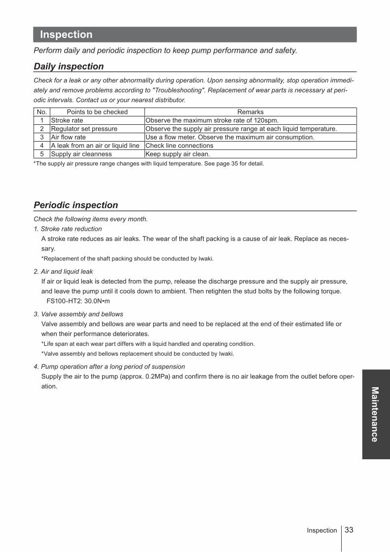
Inspection
Perform daily and periodic inspection to keep pump performance and safety.
Daily inspection
Check for a leak or any other abnormality during operation. Upon sensing abnormality, stop operation immedi-
ately and remove problems according to "Troubleshooting". Replacement of wear parts is necessary at peri-
odic intervals. Contact us or your nearest distributor.
No. Points to be checked Remarks
1 Stroke rate Observe the maximum stroke rate of 120spm.
2 Regulator set pressure Observe the supply air pressure range at each liquid temperature.
3 Air flow rate Use a flow meter. Observe the maximum air consumption.
4 A leak from an air or liquid line Check line connections
5 Supply air cleanness Keep supply air clean.
* The supply air pressure range changes with liquid temperature. See page 35 for detail.
Periodic inspection
Check the following items every month.
1. Stroke rate reduction
A stroke rate reduces as air leaks. The wear of the shaft packing is a cause of air leak. Replace as neces-
sary.
*Replacement of the shaft packing should be conducted by Iwaki.
2. Air and liquid leak
If air or liquid leak is detected from the pump, release the discharge pressure and the supply air pressure,
and leave the pump until it cools down to ambient. Then retighten the stud bolts by the following torque.
FS100-HT2: 30.0N•m
3. Valve assembly and bellows
Valve assembly and bellows are wear parts and need to be replaced at the end of their estimated life or
when their performance deteriorates.
*Life span at each wear part differs with a liquid handled and operating condition.
*Valve assembly and bellows replacement should be conducted by Iwaki.
4. Pump operation after a long period of suspension
Supply the air to the pump (approx. 0.2MPa) and confirm there is no air leakage from the outlet before oper-
ation.
Inspection
34
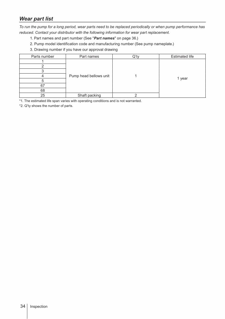
Wear part list
To run the pump for a long period, wear parts need to be replaced periodically or when pump performance has
reduced. Contact your distributor with the following information for wear part replacement.
1. Part names and part number (See "Part names" on page 36.)
2. Pump model identification code and manufacturing number (See pump nameplate.)
3. Drawing number if you have our approval drawing
Parts number Part names Q’ty Estimated life
1
Pump head bellows unit 11 year
2
3
4
5
67
68
25 Shaft packing 2
*1. The estimated life span varies with operating conditions and is not warranted.
*2. Q'ty shows the number of parts.
Inspection

35
Sp
ecifi
catio
nsSpecification/Outer dimension
Specification/Outer dimension
Specification
Information in this section is subject to change without notice.
Pump
Items Spec
Operating conditions
Max. flow rate*¹ 100L/min
Max. stroke rate 120spm
Suction lift*² 2m
Pump connection 1¼" PFA tube (I.D. 28 mm × O.D. 31.8mm)
Supply air port I.D. Rc1/2"
Max. air consumption 1208NL/min
Liquid temperature range 10-100ºC 101-140ºC 141-180ºC
Max. supply air pressure 0.15-0.5MPa 0.15-0.4MPa 0.15-0.3MPa
Allowable ambient temperature 10-60ºC
Driving method Pneumatic drive
Performance
Manufacturer KEYENCE CORPORATION
Model EZ-18T
Lead wire length 5m
Lead wire colour Brown/Black/Blue
Leak sensor Lead wire length 5m
*1. The maximum flow rate is based on pumping clean water of 25ºC.
*2. The suction lift is based on pumping clean water at an ambient temperature and the maximum spm.
Outer dimension
FS-100HT2
Weight: 47kg
448
562
13 13
185
302(51)
12
9.5
15
8.5
279.5
(81)Supply air port 2×Rc1/2
2×ø31.8×ø28.0
36 Specification/Outer dimension
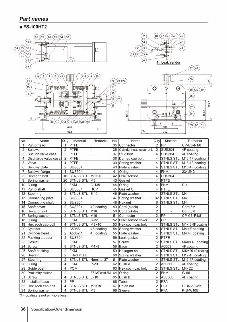
Part names
FS-100HT2
No. Name Q'ty Material Remarks No. Name Q'ty Material Remarks
1 Pump head 1 PTFE 35 Connector 2 PP CP-C8-R1/8
2 Bellows 2 PTFE 36 Cylinder head cover unit 2 SUS304 4F coating
3 Suction valve case 2 PTFE 37 Stud bolt 4 SUS304 4F coating
4 Discharge valve case 2 PTFE 38 Domed cap bolt 4 STNLS STL M16 4F coating
5 Valve 4 PTFE 39 Spring washer 4 STNLS STL M16 4F coating
6 Bellows plate 2 SUS304 40 Plate washer 4 STNLS STL M16 4F coating
7 Bellows flange 4 SUS304 41 O ring 4 FKM 234.5×2
8 Hexagon bolt 16 STNLS STL M8×20 42 Leak sensor 4 SUS304
9 Spring washer 20 STNLS STL M8 43 Gasket 4 PTFE
10 O ring 2 FKM G-135 44 O ring 4 FKM P-4
11 Pump shaft 2 SUS304 HCP 45 Gasket C 4 PTFE
12 Stop ring 2 STNLS STL E-19 46 Plate washer 4 STNLS STL M4
13 Connecting plate 2 SUS304 47 Spring washer 32 STNLS STL M4
14 Connecting shaft 2 SUS304 48 Hex nut 8 STNLS STL M4
15 Shaft cover 2 SUS304 4F coating 49 Cord (black) 2 - Cord 5M
16 Hexagon nut 2 STNLS STL M16 50 Cord (white) 2 - Cord 5M
17 Spring washer 2 STNLS STL M16 51 Connector 2 PP CP-C6-R1/8
18 O ring 2 FKM S-32 52 Leak sensor cover 2 PP
19 Hex soch cap bolt 4 STNLS STL M8×40 53 Hex soch cap bolt 4 STNLS STL M4×16 4F coating
20 Cylinder 2 A5056 4F coating 54 Spring washer 4 STNLS STL M4 4F coating
21 Cylinder head 2 A5052P 4F coating 55 Plate washer 4 STNLS STL M4 4F coating
22 Packing stopper 2 SUS304 56 Leak gasket 2 PTFE
23 Gasket 2 FKM 57 Screw 12 STNLS STL M4×8 4F coating
24 Screw 8 STNLS STL M4×8 58 Base 2 A6063 4F coating
25 Shaft packing 2 FKM 59 Hexagon bolt 4 STNLS STL M12×25 4F coating
26 Bearing 2 Filled PTFE 60 Spring washer 4 STNLS STL M12 4F coating
27 Stop ring 2 STNLS STL Nominal 37 61 Plate washer 4 STNLS STL M12 4F coating
28 O ring 4 FKM P-20 62 Bush A 2 A5056B 4F coating
29 Guide bush 4 POM 63 Hex soch cap bolt 24 STNLS STL M4×22
30 Proximity switch 2 - EZ-18T cord 5M 64 O ring 2 FKM G-55
31 Screw 4 STNLS STL 3×10 65 Bush B 4 A5056B 4F coating
32 Installed base 2 PP 66 Tube 2 PFA
33 Hex soch cap bolt 4 STNLS STL M3×18 67 Union nut 2 PFA P-UN-10WB
34 Spring washer 4 STNLS STL M3 68 Sleeve 2 PFA P-S-W10B
*4F coating is not pin-hole less.
448
13
185
302
129.5
158.5
279.5
1 5 4 20
13
25
16 17
11 27 26 64
89 7 2 41
21
10
6
18 3
59 60 61
58
66
N
57
13
22 23 24
36
38 39 40
35
562
12
(51)
(81)
67 68
14152829
323334
3031
65
19
62
63
37
4950
42
43
44
48 47 4546
51
52
56
535455
N: Leak sendor

37
Sp
ecifi
catio
nsSpecification/Outer dimension

38

39

T808 '11/12
( )Country codes
IWAKI CO.,LTD. 6-6 Kanda-Sudacho 2-chome Chiyoda-ku Tokyo 101-8558 Japan
TEL:(81)3 3254 2935 FAX:3 3252 8892
Australia IWAKI Pumps Australia Pty. Ltd. TEL : (61)2 9899 2411 FAX : 2 9899 2421 Italy IWAKI Italia S.R.L. TEL : (39)0444 371115 FAX : 0444 335350
Austria IWAKI EUROPE GmbH TEL : (49)2154 9254 0 FAX : 2154 9254 48 Korea IWAKI Korea Co.,Ltd. TEL : (82)2 2630 4800 FAX : 2 2630 4801
Belgium IWAKI Belgium n.v. TEL : (32)1367 0200 FAX : 1367 2030 Malaysia IWAKIm Sdn. Bhd. TEL : (60)3 7803 8807 FAX : 3 7803 4800
China IWAKI Pumps (Shanghai) Co., Ltd. TEL : (86)21 6272 7502 FAX : 21 6272 6929 Norway IWAKI Norge AS TEL : (47)23 38 49 00 FAX : 23 38 49 01
China IWAKI Pumps (Guandong) Co., Ltd. TEL : (86)750 3866228 FAX : 750 3866278 Singapore IWAKI Singapore Pte. Ltd. TEL : (65)6316 2028 FAX : 6316 3221
China GFTZ IWAKI Engineering & Trading (Guangzhou) TEL : (86)20 8435 0603 FAX : 20 8435 9181 Spain IWAKI Iberica Pumps, S.A. TEL : (34)943 630030 FAX : 943 628799
China GFTZ IWAKI Engineering & Trading (Beijing) TEL : (86)10 6442 7713 FAX : 10 6442 7712 Sweden IWAKI Sverige AB TEL : (46)8 511 72900 FAX : 8 511 72922
Denmark IWAKI Nordic A/S TEL : (45)48 24 2345 FAX : 48 24 2346 Switzerland IWAKI (Schweiz) AG TEL : (41)26 674 9300 FAX : 26 674 9302
Finland IWAKI Suomi Oy TEL : (358)9 2745810 FAX : 9 2742715 Taiwan IWAKI Pumps Taiwan Co., Ltd. TEL : (886)2 8227 6900 FAX : 2 8227 6818
France IWAKI France S.A. TEL : (33)1 69 63 33 70 FAX : 1 64 49 92 73 Taiwan IWAKI Pumps Taiwan (Hsin-chu) Co., Ltd. TEL : (886)3 573 5797 FAX : (886)3 573 5798
Germany IWAKI EUROPE GmbH TEL : (49)2154 9254 0 FAX : 2154 9254 48 Thailand IWAKI (Thailand) Co.,Ltd. TEL : (66)2 322 2471 FAX : 2 322 2477
Holland IWAKI EUROPE NL Branch TEL : (31)547 293 160 FAX : 547 292 332 U.K. IWAKI Pumps (UK) LTD. TEL : (44)1743 231363 FAX : 1743 366507
Hong Kong IWAKI Pumps Co., Ltd. TEL : (852)2 607 1168 FAX : 2 607 1000 U.S.A. IWAKI AMERICA Inc. TEL : (1)508 429 1440 FAX : 508 429 1386
Indonesia IWAKI Singapore (Indonesia Branch) TEL : (62)21 690 6606 FAX : 21 690 6612 Vietnam IWAKI pumps Vietnam Co.,Ltd. TEL : (84)613 933456 FAX : 613 933399