safety integrated - siemens integrity level (sil) sil 1, sil 2, sil 3 en iso 13849-1: 2006 ... e =...
TRANSCRIPT
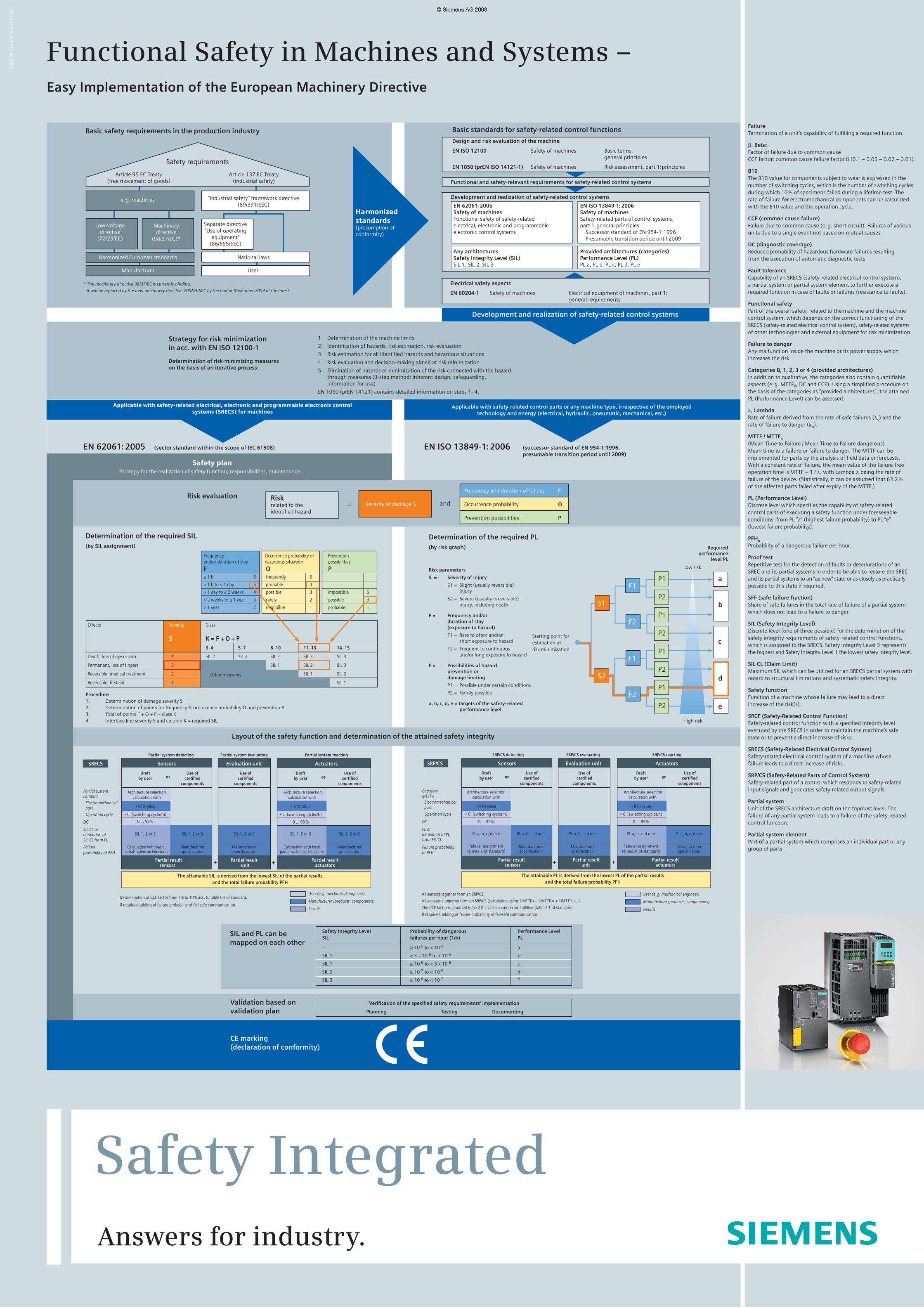
Basic safety requirements in the production industry Basic standards for safety-related control functions
Design and risk evaluation of the machine
EN ISO 12100 Safety of machines Basic terms, general principles
EN 1050 (prEN ISO 14121-1) Safety of machines Risk assessment, part 1: principles
Functional and safety-relevant requirements for safety-related control systems
Development and realization of safety-related control systems
EN 62061: 2005Safety of machines Functional safety of safety-related electrical, electronic and programmableelectronic control systems
Any architecturesSafety Integrity Level (SIL)SIL 1, SIL 2, SIL 3
EN ISO 13849-1: 2006Safety of machinesSafety-related parts of control systems, part 1: general principles Successor standard of EN 954-1: 1996 Presumable transition period until 2009
Provided architectures (categories)Performance Level (PL)PL a, PL b, PL c, PL d, PL e
Electrical safety aspects
EN 60204-1 Safety of machines Electrical equipment of machines, part 1: general requirements
1. Determination of the machine limits
2. Identifi cation of hazards, risk estimation, risk evaluation
3. Risk estimation for all identifi ed hazards and hazardous situations
4. Risk evaluation and decision-making aimed at risk minimization
5. Elimination of hazards or minimization of the risk connected with the hazard through measures (3-step method: inherent design, safeguarding,information for use)
EN 1050 (prEN 14121) contains detailed information on steps 1–4.
Strategy for risk minimization in acc. with EN ISO 12100-1
Determination of risk-minimizing measures on the basis of an iterative process:
Development and realization of safety-related control systems
Applicable with safety-related electrical, electronic and programmable electronic control systems (SRECS) for machines
Applicable with safety-related control parts or any machine type, irrespective of the employed technology and energy (electrical, hydraulic, pneumatic, mechanical, etc.)
EN 62061: 2005 (sector standard within the scope of IEC 61508) EN ISO 13849-1: 2006 (successor standard of EN 954-1:1996, presumable transition period until 2009)
Safety planStrategy for the realization of safety function, responsibilities, maintenance…
Risk evaluationSeverity of damage S
Riskrelated to the identifi ed hazard
Frequency and duration of failure F
Occurrence probability O
Prevention possibilities P
= and
Determination of the required SIL(by SIL assignment)
Procedure1. Determination of damage severity S2. Determination of points for frequency F, occurrence probability O and prevention P 3. Total of points F + O + P = class K4. Interface line severity S and column K = required SIL
a
b
c
d
e
Layout of the safety function and determination of the attained safety integrity
Safety Integrity Level Probability of dangerous Performance LevelSIL failures per hour (1/h) PL
– ≥ 10-5 to < 10-4 a
SIL 1 ≥ 3 x 10⁻⁶ to < 10-5 b
SIL 1 ≥ 10-6 to < 3 x 10⁻⁶ c
SIL 2 ≥ 10-7 to < 10-6 d
SIL 3 ≥ 10-8 to < 10-7 e
oror
CE marking (declaration of conformity)
oror
Other measures
F1
F2
F1
F2
S1
S2
P1
P2
P1
P2
P1
P2
P1
P2
+++ +
SIL and PL can be mapped on each other
Validation based on validation plan
Verifi cation of the specifi ed safety requirements’ implementation
Planning Testing Documenting
Functional Safety in Machines and Systems –Easy Implementation of the European Machinery Directive
Safety requirements
Article 95 EC Treaty(free movement of goods)
Article 137 EC Treaty(industrial safety)
e. g. machines
Low-voltage directive
(72/23/EC)
Machinery directive
(98/37/EC)*
Harmonized European standards
Manufacturer
* The machinery directive 98/37/EC is currently binding.
It will be replaced by the new machinery directive 2006/42/EC by the end of November 2009 at the latest.
”Industrial safety“ framework directive (89/391/EEC)
Separate directive ”Use of operating
equipment“ (86/655/EEC)
National laws
User
Harmonized standards(presumption of conformity)
Effects Severity Class
S K = F + O + P 3–4 5–7 8–10 11–13 14–15
Death, loss of eye or arm 4 SIL 2 SIL 2 SIL 2 SIL 3 SIL 3
Permanent, loss of fi ngers 3 SIL 1 SIL 2 SIL 3
Reversible, medical treatment 2 SIL 1 SIL 2
Reversible, fi rst aid 1 SIL 1
Frequency Occurrence probability of Preventionand/or duration of stay hazardous situation possibilities
F O P≤ 1 h 5 frequently 5
> 1 h to ≤ 1 day 5 probable 4
> 1 day to ≤ 2 weeks 4 possible 3 impossible 5
> 2 weeks to ≤ 1 year 3 rarely 2 possible 3
> 1 year 2 negligible 1 probable 1
Determination of the required PL(by risk graph)
Risk parameters
S = Severity of injury
S1 = Slight (usually reversible) injury
S2 = Severe (usually irreversible) injury, including death
F = Frequency and/or duration of stay (exposure to hazard)
F1 = Rare to often and/or short exposure to hazard
F2 = Frequent to continuous and/or long exposure to hazard
P = Possibilities of hazard prevention or damage limiting
P1 = Possible under certain conditions
P2 = Hardly possible
a, b, c, d, e = targets of the safety-related performance level
Low risk
High risk
Required performance
level PL
Starting point for estimation of risk minimization
Determination of CCF factor from 1% to 10 % acc. to table F.1 of standard.
If required, adding of failure probability of fail-safe communication.
User (e. g. mechanical engineer)
Manufacturer (products, components)
Results
Partial system detecting Partial system evaluating Partial system reacting
SRECS Sensors Evaluation unit Actuators
Draft Use of Use of Draft Use of by user certifi ed certifi ed by user certifi ed components components components
Partial system Architecture selection Architecture selectionLambda calculation with calculation with
Electromechanical part • B10 value • B10 value
Operation cycle • C (switching cycles/h) • C (switching cycles/h)
DC 0 ... 99 % 0 ... 99 %
SIL CL or SIL 1, 2 or 3 SIL 1, 2 or 3 SIL 1, 2 or 3 SIL 1, 2 or 3 SIL 1, 2 or 3derivation of
SIL CL from PL
Failure Calculation with basic Manufacturer Manufacturer Calculation with basic Manufacturerprobability of PFH partial system architectures specifi cation specifi cation partial system architectures specifi cation
Partial result Partial result Partial result sensors unit actuators
The attainable SIL is derived from the lowest SIL of the partial results and the total failure probability PFH
User (e. g. mechanical engineer)
Manufacturer (products, components)
Results
All sensors together form an SRP/CS.
All actuators together form an SRP/CS (calculation using 1/MTTFd = 1/MTTFd1 + 1/MTTFd2...).
The CCF factor is assumed to be 2 % if certain criteria are fulfi lled (table F.1 of standard).
If required, adding of failure probability of fail-safe communication.
SRP/CS detecting SRP/CS evaluating SRP/CS reacting
SRP/CS Sensors Evaluation unit Actuators
Draft Use of Use of Draft Use of by user certifi ed certifi ed by user certifi ed components components components
Category Architecture selection Architecture selectionMTTFd calculation with calculation with
Electromechanicalpart • B10 value • B10 value
Operation cycle • C (switching cycles/h) • C (switching cycles/h)
DC 0 ... 99 % 0 ... 99 %
PL or PL a, b, c, d or e PL a, b, c, d or e PL a, b, c, d or e PL a, b, c, d or e PL a, b, c, d or ederivation of PL
from SIL CL
Failure probability Tabular assignment Manufacturer Manufacturer Tabular assignment Manufacturer
or PFH (annex K of standard) specifi cation specifi cation (annex K of standard) specifi cation
Partial result Partial result Partial result sensors unit actuators
The attainable PL is derived from the lowest PL of the partial results and the total failure probability PFH
Failure Termination of a unit’s capability of fulfi lling a required function.
�, Beta:Factor of failure due to common cause CCF factor: common cause failure factor ß (0.1 – 0.05 – 0.02 – 0.01).
B10The B10 value for components subject to wear is expressed in the number of switching cycles, which is the number of switching cycles during which 10 % of specimens failed during a lifetime test. The rate of failure for electromechanical components can be calculated with the B10 value and the operation cycle.
CCF (common cause failure) Failure due to common cause (e. g. short circuit). Failures of various units due to a single event not based on mutual causes.
DC (diagnostic coverage)Reduced probability of hazardous hardware failures resulting from the execution of automatic diagnostic tests.
Fault tolerance Capability of an SRECS (safety-related electrical control system), a partial system or partial system element to further execute a required function in case of faults or failures (resistance to faults).
Functional safety Part of the overall safety, related to the machine and the machine control system, which depends on the correct functioning of the SRECS (safety-related electrical control system), safety-related systems of other technologies and external equipment for risk minimization.
Failure to danger Any malfunction inside the machine or its power supply which increases the risk.
Categories B, 1, 2, 3 or 4 (provided architectures)In addition to qualitative, the categories also contain quantifi able aspects (e. g. MTTFd, DC and CCF). Using a simplifi ed procedure on the basis of the categories as ”provided architectures“, the attained PL (Performance Level) can be assessed.
�, LambdaRate of failure derived from the rate of safe failures (�
S) and the
rate of failure to danger (�D).
MTTF / MTTFd
(Mean Time to Failure / Mean Time to Failure dangerous)Mean time to a failure or failure to danger. The MTTF can be implemented for parts by the analysis of fi eld data or forecasts. With a constant rate of failure, the mean value of the failure-free operation time is MTTF = 1 / �, with Lambda � being the rate of failure of the device. (Statistically, it can be assumed that 63.2 % of the affected parts failed after expiry of the MTTF.)
PL (Performance Level)Discrete level which specifi es the capability of safety-related control parts of executing a safety function under foreseeable conditions: from PL ”a“ (highest failure probability) to PL ”e“ (lowest failure probability).
PFHD
Probability of a dangerous failure per hour.
Proof testRepetitive test for the detection of faults or deteriorations of an SREC and its partial systems in order to be able to restore the SREC and its partial systems to an ”as new“ state or as closely as practically possible to this state if required.
SFF (safe failure fraction) Share of safe failures in the total rate of failure of a partial system which does not lead to a failure to danger.
SIL (Safety Integrity Level) Discrete level (one of three possible) for the determination of the safety integrity requirements of safety-related control functions, which is assigned to the SRECS. Safety Integrity Level 3 represents the highest and Safety Integrity Level 1 the lowest safety integrity level.
SIL CL (Claim Limit)Maximum SIL which can be utilized for an SRECS partial system with regard to structural limitations and systematic safety integrity.
Safety functionFunction of a machine whose failure may lead to a direct increase of the risk(s).
SRCF (Safety-Related Control Function)Safety-related control function with a specifi ed integrity level executed by the SRECS in order to maintain the machine’s safe state or to prevent a direct increase of risks.
SRECS (Safety-Related Electrical Control System) Safety-related electrical control system of a machine whose failure leads to a direct increase of risks.
SRP/CS (Safety-Related Parts of Control System) Safety-related part of a control which responds to safety-related input signals and generates safety-related output signals.
Partial systemUnit of the SRECS architecture draft on the topmost level. The failure of any partial system leads to a failure of the safety-related control function.
Partial system elementPart of a partial system which comprises an individual part or any group of parts.
E20
00
1-Y
29
0-M
10
3-V
1-7
60
0
Safety IntegratedAnswers for industry.