safety lockout system - rockwell...
TRANSCRIPT

Safety Lockout SystemBulletin 1000
User Manual

Important User Information Because of the variety of uses for the products described in this publication, those responsible for the application and use of this control equipment must satisfy themselves that all necessary steps have been taken to assure that each application and use meets all performance and safety requirements, including any applicable laws, regulations, codes and standards.
The illustrations, charts, sample programs and layout examples shown in this guide are intended solely for purposes of example. Since there are many variables and requirements associated with any particular installation, Allen-Bradley does not assume responsibility or liability (to include intellectual property liability) for actual use based upon the examples shown in this publication.
Allen-Bradley publication SGI-1.1, Safety Guidelines for the Application, Installation and Maintenance of Solid-State Control (available from your local Allen-Bradley office), describes some important differences between solid-state equipment and electromechanical devices that should be taken into consideration when applying products such as those described in this publication.
Reproduction of the contents of this copyrighted publication, in whole or part, without written permission of Rockwell Automation, is prohibited.
Throughout this manual we use notes to make you aware of safety considerations:
Attention statements help you to:
• identify a hazard
• avoid a hazard
• recognize the consequences
Allen-Bradley is a trademark of Rockwell Automation
ATTENTION
!Identifies information about practices or circumstances that can lead to personal injury or death, property damage or economic loss.
IMPORTANT Identifies information that is critical for successful application and understanding of the product.

European Communities (EC) Directive Compliance
If this product has the CE mark it is approved for installation within the European Union and EEA regions. It has been designed and tested to meet the following directives.
EMC Directive
This product is tested to meet the Council Directive 89/336/EC Electromagnetic Compatibility (EMC) by applying the following standards, in whole or in part, documented in a technical construction file:
• EN 50081-2 EMC — Generic Emission Standard, Part 2 — Industrial Environment
• EN 50082-2 EMC — Generic Immunity Standard, Part 2 — Industrial Environment
This product is intended for use in an industrial environment.
Low Voltage Directive
This product is tested to meet Council Directive 73/23/EEC Low Voltage, by applying the safety requirements of EN 61131-2 Programmable Controllers, Part 2 — Equipment Requirements and Tests. For specific information required by EN 61131-2, see the appropriate sections in this publication, as well as the Allen-Bradley publication Industrial Automation Wiring and Grounding Guidelines For Noise Immunity, publication 1770-4.1.
This equipment is classified as open equipment and must be mounted in an enclosure during operation to provide safety protection.

Notes:

Table of Contents
Preface Purpose of the Safety Lockout System . . . . . . . . . . . . . . . . . . . Preface-1Safety Requirements and Guidelines . . . . . . . . . . . . . . . . . . . . . Preface-1Definitions . . . . . . . . . . . . . . . . . . . . . . . . . . . . . . . . . . . . . . . . . Preface-1Description of Use . . . . . . . . . . . . . . . . . . . . . . . . . . . . . . . . . . . Preface-2Simplified Wiring Diagram andSequence of Operation . . . . . . . . . . . . . . . . . . . . . . . . . . . . . . . Preface-2Application . . . . . . . . . . . . . . . . . . . . . . . . . . . . . . . . . . . . . . . . . Preface-4Specifications . . . . . . . . . . . . . . . . . . . . . . . . . . . . . . . . . . . . . . . Preface-4
Chapter 1 Installation Instructions
Chapter 2 Commissioning Box and Switch
Chapter 3 Operational ProcedureComponent Function and Description . . . . . . . . . . . . . . . . . . . . . . . . 3-1Servicing . . . . . . . . . . . . . . . . . . . . . . . . . . . . . . . . . . . . . . . . . . . . . . . . 3-3
Chapter 4 SLS Sequence of Operation
Chapter 5 Troubleshooting GuideTroubleshooting Guide . . . . . . . . . . . . . . . . . . . . . . . . . . . . . . . . . . . . 5-1SLS Test Procedure . . . . . . . . . . . . . . . . . . . . . . . . . . . . . . . . . . . . . . . 5-3
Appendix A Certification Documentation
Appendix B References
i Publication 1000-UM001B-US-P - July 2000

Table of Contents ii
Notes:
Publication 1000-UM001B-US-P - July 2000

Preface
Purpose of the Safety Lockout System
The purpose of the Safety Lockout System (SLS) is to provide a highly reliable and long-lived system for the isolation of a multi-motor machine (or portion thereof) with such isolation operable from multiple remote locations.
Safety Requirements and Guidelines
The SLS is one subsystem in the machine control system. As is true in installing any machine control system, it is necessary to follow the instructions that accompany the control system. It is further necessary to follow the requirements of the relevant regulatory bodies. These can include NFPA 70 (The National Electrical Code), NFPA 70E, NFPA 79, relevant OSHA requirements and relevant State and Local codes.
• EN 50081-2 EMC — Generic Emission Standard, Part 2 — Industrial Environment
• EN 50082-2 EMC — Generic Immunity Standard, Part 2 — Industrial Environment
Definitions Safety lockout system (SLS) — Isolation system designed to meet lockout/tagout requirements by the use of remote lockout switches, voltage supervision monitor and an isolation contactor having positive guided auxiliary contacts.
SLS box — SLS enclosure and components other than the SLS switches.
SLS switch — remote lockout switch with verification light.
Expansion box — provisions for more than four (4) SLS switches.
Positive guidance — per IEC 947-5-1 is a performance relationship between contacts of different types (i.e., N.O. and N.C.)
1 Publication 1000-UM001B-US-P - July 2000

Preface 2
Description of Use The SLS switch should not be used to initiate normal stopping of the system. The normal system stop function(s) should be used to stop the system and then, when necessary, the remote SLS switch can be used to initiate the isolation of the system. When the SLS switch is operated for the purpose of isolation, a white SAFE light will illuminate when the system is isolated. The illumination of the SAFE light is the control indication that the electrical power to the equipment on the machine fed through the SLS is de-energized and isolated.
An SLS service technician must investigate, correct and log any abnormality.
Simplified Wiring Diagram and Sequence of Operation
After using the normal stop function, the machine operator can turn the SLS switch from the ON to the OFF position and then lock the SLS switch in the OFF position. This will cause the isolation contactor (IC) to drop out and arm the SAFE pilot light. The voltage supervision relay (VSR) will then monitor the load side of the isolation contactor for voltages greater than 10V and will monitor the position of the isolation contactor through its normally closed positively guided auxiliary contact. If the voltage check is OK and the IC auxiliary contact is closed, the VSR’s safety contacts will close, illuminating the SAFE pilot light.
Publication 1000-UM001B-US-P - July 2000

Preface 3
Figure P.1 Typical SLS System Layout
PVSROFF ON
SLS SW
IC
SAFE
PVSR
IC
IC
INCOMING
LINES
MOTION BUSOR
HAZARD
Publication 1000-UM001B-US-P - July 2000

Preface 4
Figure P.2 Typical SLS System Layout
PLC
SLS EXPANSIONBOX
SLS BOX
PE
GRD INCOMING LINES
MAINDISC
DRIVE DRIVE DRIVE
STARTER
STARTER
STARTER
MAINENCLOSURE
TO MOTION BUS ONMACHINE OR HAZARD TO NON-MOTION BUS
ON MACHINE ORNON-HAZARD
TO
SLS
SWITCHES
Publication 1000-UM001B-US-P - July 2000

Preface 5
Application The SLS is an isolation system designed to provide disconnection and isolation. This means that the SLS provides the isolation necessary for work on machine elements electrically powered through the SLS and for work on the electrical equipment powered by SLS. However, the forgoing speaks to the capability of the SLS, not necessarily its use as assigned by management for a given purpose.
Since the SLS illuminates the SAFE light, it is imperative that the SLS be applied only where it disables all forms of energy and after a risk analysis has been performed.
Specifications A. Electrical Ratings• Supply Voltage 480V, 60 Hz and 400V, 50 Hz• Contactor Ampacity 30, 85
(in conformance with clause 5.7.1 of NFPA 79: 1997, and clause 4.3.2 of EN 60204-1: 1997)
B. Estimated system life• SLS box
– Electrical 1,000,000 operations– Mechanical 10,000,000 operations
• SLS switch– Electrical 200,000 operations– Mechanical 200,000 operations
C. Environmental• Storage temperature –30…+85°C• Operating temperature, Ambient –10…+40°C• Relative humidity, Non-Condensing 90% RH
D. Electromagnetic Interference
Compliant with EMC Directives
E. Reliability
System reliability is indicated by FMEA analysis.
F. Safety Lockout System
Certified by TUV (Northbrook, IL) for category 4 EN 954-1: 1996, and EN 60204-1
Publication 1000-UM001B-US-P - July 2000

Preface 6
G. Construction
The SLS box enclosure is primarily provided to prevent tampering with the SLS components and circuitry and, as such, is designed and listed per UL 508A to be installed inside another enclosure. The SLS box is constructed with a large transparent viewing window in the cover necessary to easily observe the status of the LED indicators. Both the SLS box and the SLS switch are provided with special holes placed to accommodate tamper-resistant sealing.
H. Construction Rating (for SLS switch only)
NEMA4/IP65
Publication 1000-UM001B-US-P - July 2000

Chapter 1
Installation Instructions
A. The SLS box enclosure has no environmental rating. Its purpose is to prevent tampering with the safety system and allow viewing of the components. The SLS box shall be mounted in a parent enclosure of suitable environmental rating with sufficient space to allow free opening of its door and convenient wiring of its connectors.
B. After installation the SLS system must be tested for proper operation and certified as such by a SLS trained service technician, who then seals the SLS box and the SLS switches. The engineer responsible for the process or machine shall keep a service logbook of this and all future servicing. Servicing is to be performed only by SLS qualified technicians.
C. SLS cable and cable installation specification1. Cable must be installed so that it is protected from physical damage.
This may require conduit.2. Cable must have a shield with a drain wire connected to ground at
the SLS box.3. Cable insulated for 600V is recommended.4. Cable shall have copper conductors only.5. Maximum SLS switch circuit length (total length of wire run):
#14 AWG (2.5 mm2) = 4600 ft (1403 m)#16 AWG (1.5 mm2) = 2600 ft (793 m)#18 AWG (0.75 mm2) = 1300 ft (397 m)
6. Individual conductors within a cable shall be color coded or otherwise clearly marked.Suggested source and type of cable:
For SLS switches — Alpha wire Xtra-Guard 2 Part #25450/9 for #14 AWG 0.64" O.D., Part #25440/9 for #16 AWG 0.61" O.D., and Part #25430/9 for #18 AWG 0.55" O.D.(SLS switch cable must not be run with power conductors.)
D. SLS box ground bus must be bonded to the system ground bus in the main enclosure as follows:1. For 85 A SLS box with Pilz relay (Cat. No. 1000-NXSLSV85) use
#8 AWG (10 mm2).2. For 30 A SLS box with Pilz relay (Cat. No. 1000-NXSLSV30) use
#10 AWG (6 mm2).
1 Publication 1000-UM001B-US-P - July 2000

1-2 Installation Instructions
Note: If the Class J fuses protecting the SLS box are smaller than that specified, the equipment grounding conductor may be reduced to that as shown in Table 250-95 of the NEC.
E. This SLS box has Harting connectors for four SLS switches with safe light (Cat. No. 1000-NXSLS). If less than that four are needed for an installation, jumper out the unneeded SLS switches in the male end of the Harting connector. Refer to wiring diagram Y-155798.
Example: If SLS #4 is not needed, remove the hood on the male Harting SLS connector and install a jumper between pins #3 and #8 on the insert and install another jumper between pins #4 and #9 on the insert. This will jumper out the missing SLS switch #4. Re-install the hood and clamp the male Harting connector back in the SLS #4 position.
F. If an installation requires more than four SLS switches, an expansion box(es) can be installed to increase the total number of SLS switches. Refer to drawings Y-156773 and Y-157131.
G. The SLS enclosure must be bolted to the mounting plate of an enclosure in the vertical position. Refer to drawing YD-24475 for mounting dimensions.
H. The SLS box must be protected upstream from the isolation contactor by a Class J time delay fuse. Maximum available fault current is 42 KA at 480V. In order to ensure IEC 947-4-1 Type 2 or better protection, fuses are to be sized per NEC Article 430 part D, but shall not exceed the following:
85 A contactor size = 100 A max.30 A contactor size = 30 A max.
I. Power wire size and terminal torque
J. SLS switch installation1. Mount in the vertical plane per drawing YD-24492.2. Use conduit and hub or strain relief cord grip.3. Connect SLS cable to terminal blocks that correspond to the pin
numbers on the Harting connectors per drawing Y-156328.
Table 1.A
SLS Rating Cat. No. Power Wire Size Terminal Torque
30 A with Pilz relay 1000-NXSLSV30 #14…#6 AWG(2.5…16 mm2)
31 lb-in. (3.5 Nm)+0%…5%
85 A with Pilz relay 1000-NXSLSV85 #14…#2 AWG(2.5…50 mm2)
52 lb-in. (6 Nm)+0%…5%
Publication 1000-UM001B-US-P - July 2000

Chapter 2
Commissioning Box and Switch
This procedure is to be followed at first time startup and any subsequent SLS service.
A. Inspection1. Visually inspect enclosure and components for damage that may
have occurred in installation or shipment. Look for loose wires or damaged components.
2. For first time installation, remove adhesive protective paper cover from SLS box window.
3. Check incoming and outgoing three phase power lines for proper selection and sizing. Select per NEC article 430 part B and size per NEC table 310-16, 75°C column. Note that the preferred wire, MTW, is rated 90°C, but it must be sized per the 75°C column.
4. Check incoming and outgoing lines along with associated line voltage control wires that attach to the isolation contactor for proper torque. Refer to wiring diagram for values. Also check that the lugs do not crimp down on the wire insulation.
5. Check to see that the proper class J time delay fuse is installed ahead of the SLS box. Refer to wiring diagram notes and see item H under “Installation Instructions”.
6. Check to see that the proper size grounding conductor has been installed between the ground bus in the main enclosure and the ground bus in the SLS box (refer to item D under “Installation Instructions”). Refer to NEC Table 250-66 for sizing.
7. Verify that the SLS switches are connected to the SLS box and that unneeded SLS switches are jumpered out in the Harting connectors as per item E under “Installation Instructions”.
8. Inspect SLS cable installation for protection against damage. Refer to item C under “Installation Instructions”.
9. If required, check to see that white phenolic nameplate on the SLS switch cover is engraved as specified. Also check to see that screws that secure this nameplate to cover are resealed on the inside of cover when nameplate is replaced. This is to ensure NEMA Type 4 (IP65) watertight construction.
10.Verify that the control transformer primary and secondary is connected per the system voltage per note #4 on wiring diagram Y-155798. Refer to Appendix A.
1 Publication 1000-UM001B-US-P - July 2000

2-2 Commissioning Box and Switch
B. Verification of SLS operation1. Turn all SLS switches to the ON position.2. Check the machine to see that damage or injury will not occur if the
machine is started.3. Energize the motion bus that the SLS box contactor controls.4. Check for machine operation and by operating with the normal start
and stop functions. Check to see that the signals to the PLC and drive are correct. Leave machine in the stopped mode.
5. Observe LEDs in SLS box for the following conditions:• Power supply DC ON = on.• VSR — POWER = on.• Safety relay 1SR — POWER ON, CH1, CH2, K1, K2 = on.• Safety relay SR — POWER ON, CH1, CH2, K1, K2 = on.• LED terminal blocks — PLUS = on, 12 = off, MINUS = on.
6. All SLS switch SAFE lights should be off.7. Check voltage on secondary of CCT.8. Measure DC voltage on power supply output. If necessary, adjust to
27V.9. One at a time, check the operation of each SLS switch by turning it
to the OFF position. Then check for the following:• SAFE light on.• IC dropped out.• 1CR dropped out (refer to cross bar).• Safety relay dropped out, LED — POWER ON = on, CH1, CH2,
K1, K2 = off.• VSR indicates safe condition. LED — POWER = on, six phase
voltages = off.• LED T.B. — PLUS = on, 12 = on, MINUS = on
C. To provide an indication of tampering, seal the SLS box, theSLS switches and the Harting connectors with a tamper-resistant indicating seal. There are holes in the right hand side of the enclosures for this and in the Harting connectors.
D. A service log shall be kept for each SLS box that keeps track of the following:1. Serial number of SLS box2. Date of commissioning3. Name of SLS commissioning technician4. Name of the SLS service technician5. Description of service performed6. Date of service
Publication 1000-UM001B-US-P - July 2000

Chapter 3
Operational Procedure
The machine operator should not use the SLS to perform a normal stop function. The SLS should only be used to isolate the system. Machine access is allowed only after the SLS switch is locked and tagged in the OFF position and the white SAFE light is illuminated to verify that the system is indeed isolated. If the white SAFE light fails to illuminate when the SLS switch is turned to the OFF position, the machine cannot be considered isolated nor safe. The operator should not enter the machine, but should contact a SLS qualified service technician.
Component Function and Description
Table 3.A SLS Box
Component Cat. No. Source Description Repairable Function
Enclosure 32267-121-51 Allen-Bradley See-through cover Provides segregation and protection of the SLS components.
Mounting plate 32267-122-02 Allen-Bradley Mounts equipment.
Control transformer
B075-1017-GA Micron 480/400 – 120/110V No Provides 120V for control circuit.
Primary fuse block 1492-FB2C30-L Allen-Bradley Class CC rejection type with blown fuse indication
No Secures fuse and indicates status.
Primary fuses KLDR Allen-Bradley or Littlefuse
Class CC fuse No Protects CCT primary.
Secondary fuse block
1492-FB1C30-L Allen-Bradley Class CC rejection type with blown fuse indication
No Secures and indicates status.
Secondary fuse KLDR Allen-Bradley or Littlefuse
Class CC fuse No Protects CCT secondary.
Power supply PS5R-C/50W 24V IDEC Current limiting 24V DC with LED
No Provides current limited 24V DC for SLS circuit.
Safety contactor 100S-C85D04C Allen-Bradley 85 A IEC safety contactor, 120V coil
No Provides isolation and status through N.C. positive guided auxiliary.
2 N.O. auxiliary 100-SA20 Allen-Bradley 2 N.O. auxiliary No Provides control circuits with positive guidance and monitoring of power poles.
Surge suppressor 100-FSC280 Allen-Bradley 120V RC type No Absorbs coil spikes.
1 Publication 1000-UM001B-US-P - July 2000

3-2 Operational Procedure
Pilz relay PU3Z 24VDV Pilz Voltage supervision and contactor monitoring safety relay
No Monitors position of contactor and voltage on load side of contactor.
Safety relay SR 700-ZBL220Z24 Allen-Bradley 24V safety relay No Checks for cable integrity and for operation of the SLS switch.
Safety relay 1SR Allen-Bradley 24V safety relay Yes Serves as E-stop, pilot relay, and PLC interface.
1CR 700-CF220DJ Allen-Bradley 24V DC control relay Yes Keeps safe light out if the SR safety relay faults.
Protective cover 100-SCCA Allen-Bradley Protective cover No Prevents manual operation.
Terminal blocks 1492-H1 Allen-Bradley Terminal blocks No Provides connections.
LED terminal blocks
1492-HM2V24 Allen-Bradley LED terminal blocks No Provides indication of voltage presence.
Harting connectors See Renewal Parts List
Harting Plug-in connectors Yes Provides quick connection and indication of tampering if sealed.
Table 3.A SLS Box (Continued)
Component Cat. No. Source Description Repairable Function
Table 3.B SLS Switch
Component Cat. No. Source Description Repairable Function
Enclosure 32267-132-51 Allen-Bradley NEMA Type 4 SS enclosure
Provides protection for SLS components. Allows for tamper indication if sealed.
Mounting plate 32267-133-01 Allen-Bradley Mounts components
Operating handle 194R-HS4 Allen-Bradley Lockable position indicating operating handle
No Operates and provides for lockout. Enclosure cannot be opened when locked out.
Pilot light 800H-QR24W Allen-Bradley White 24V DC pilot light Yes Signals SAFE.
SLS switch 194E-A25-1753 Allen-Bradley 3-pole disconnect switch No Provides redundant signal through safety relay.
SLS switch auxiliary contact
194E-A-P11 Allen-Bradley Auxiliary contact No Provides SLS status to PLC.
Publication 1000-UM001B-US-P - July 2000

Operational Procedure 3-3
Servicing A. Servicing is only to be performed by qualified SLS technician.
B. Due to the nature of this controller and the type of equipment used, most all components are deemed non-repairable and should be replaced (not repaired) if they are not functioning properly.
C. Refer to Allen-Bradley wiring diagram Y-156594. This is a schematic for the 700-ZBL220Z24 and should aid in further understanding of the operation of the SLS switches and the safety relays. Refer toAppendix A.
D. Reference to renewal parts list.
For renewal parts identification and placement refer to Allen-Bradley document #49103-063-01 (SLS box) and #49000-064-01(SLS switch). Refer to Appendix A.
E. Refer to Allen-Bradley drawaing Y-156386 for test set-up.
F. The entire SLS box may be returned to the factory for repair and/or testing. Consult your local Allen-Bradley Sales Office regarding a Product Service Report (PSR) to initiate a factory repair.
Publication 1000-UM001B-US-P - July 2000

3-4 Operational Procedure
Notes:
Publication 1000-UM001B-US-P - July 2000

Chapter 4
SLS Sequence of Operation
The following is the sequence of operation for the SLS box and the SLS switch as shown on Y-155798 Rev. M and Y-156328 Rev. B. The intention is to provide an understanding of circuit operation and equipment function. This will be an aid in troubleshooting because if the sequence stops or is incomplete, the suspected part or failure may be narrowed down and identified. Assumptions are made that the SLS has been installed properly, no fuses are blown, power is on, all equipment is functioning correctly and all SLS switches are in the ON position
A. Status1. IC is open.2. Power supply LED is on.3. Pilz PU3Z power LED on.4. All SLS switch SAFE lights are off.5. All safety relay LEDs are on.6. 1CR is energized (refer to cross bar).7. Blown fuse pilot lights are off.8. TB LEDs between + and – are on.
B. The remote 24V DC signal is applied to 1SR at TB#34 and TB#35 causing it to close the circuit between wires #4 and #5.
C. Since the safety relay 1SR is energized and its contacts between #13 and #14 are closed, IC will be energized, actuating the IC auxiliary contacts and sending power to the motion bus.
1 Publication 1000-UM001B-US-P - July 2000

4-2 SLS Sequence of Operation
D. If an operator moves the SLS switch from ON to OFF, the following will happen:1. The safety relay circuit between terminals S10 and S11, and S21 and
S2 will open up to de-energize the safety relay, causing the safety contacts terminals #13 and #14 between wires #1 and #3 to open up. In addition, safety relay auxiliary contacts between terminals #33 and #34 and #43 and #44 will open dropping out 1CR. This will cause IC to open up. Note: If one of the contacts on the SLS switch does not open, or if there is a short in the cable to the SLS switch, only one of the safety relay contacts K1 or K2 will drop out IC. But, the safety relay will lock up and not allow a re-start. Now, since one of the safety relay auxiliary contacts K1 or K2 will remain closed, 1CR will remain energized, preventing the SAFE pilot light from illuminating. Also, if the contacts IC and 1CR between terminals S41 and S42 on the safety relay have not re-closed, the safety relay will not allow a restart.
2. After IC has dropped out, the VSR will check for voltages greater than 10V on the load side of IC through its redundant and broken wire sensing circuit. The VSR will also check to see that the N.C. positively guided auxiliary contact between wire #7 and #8 on IC is closed. If these two conditions are met, the VSR will close the safety contacts between its terminals #13 and #14.
3. Since the auxiliary contact of IC between ++ and wire #10 is closed, the 1CR contact between wires #10 and #11 is closed, the safety contacts between wire #11 and #12 are closed, and the SLS switch contact between wire #12 and the SAFE pilot light is closed, the SAFE pilot light will illuminate. The TB led between wire #12 and – is on.
E. The SAFE pilot light will not come on with the SLS switch in the off position if:1. The VSR detects a voltage greater than 10V on the load side IC.2. The VSR detects that the positively guided N.C. auxiliary IC contact
between wires #7 and #8 has not re-closed.3. A safety relay auxiliary contact does not allow 1CR to drop out and
close circuit between wires #10 and #11.4. The IC auxiliary contact between wires PLUS and #10 does not
re-close.
Publication 1000-UM001B-US-P - July 2000

SLS Sequence of Operation 4-3
F. If the SLS switch is moved back to the ON position the following will happen:1. The SLS switch contacts between the safety relay terminals S10 and
S11, and S21 and B2 will close to energize the safety relay. This causes the safety contacts between terminals #13 and #14 between wires #1 and #3 to close.Note: The SLS switch contacts must close at approximately the same time or the safety relay will lock up. This may denote an SLS switch or cable failure. Also, the contacts IC and 1CR between terminals S41 and S42 must be closed or the safety relay will not energize. This may indicate a failure of IC, 1CR, the SLS switch or the cable. Plus, safety relay auxiliary contacts between terminals #33 and #34, and #43 and #44 will close energizing 1CR.
2. Since 1SR between wires #4 and #5 is closed along with 1CR between wires #3 and #4, and the safety relay SR output contacts between terminals #13 and #14 are also closed, IC will close its output power contacts.
3. The PVSR will detect a voltage and see that the circuit between terminals Y4 and Y5 is open, causing the safety contacts between terminals #13 and #14 PVSR to open.
4. All contacts in series with the SAFE light should now be open and the SAFE light will now be off. The TB led betweenwire #12 and – will be off.
Publication 1000-UM001B-US-P - July 2000

4-4 SLS Sequence of Operation
Notes:
Publication 1000-UM001B-US-P - July 2000
Chapter 5
Troubleshooting Guide
Troubleshooting Guide
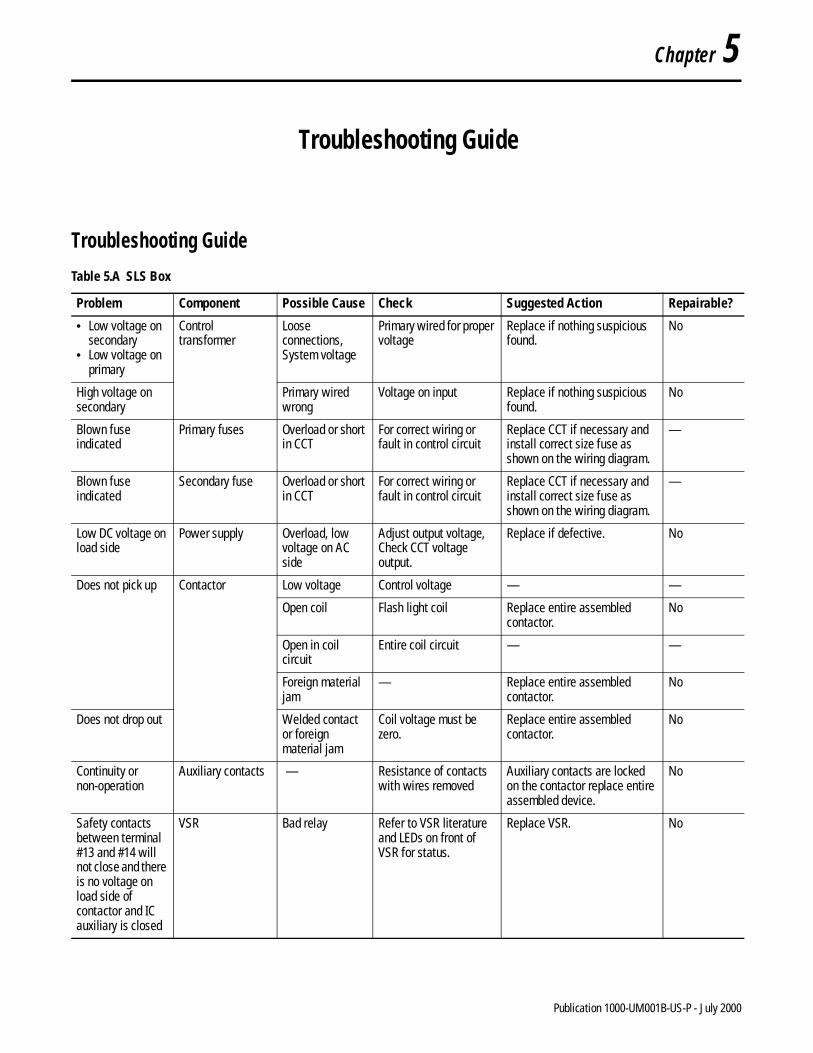
Table 5.A SLS Box
Problem Component Possible Cause Check Suggested Action Repairable?
• Low voltage on secondary
• Low voltage on primary
Control transformer
Loose connections,System voltage
Primary wired for proper voltage
Replace if nothing suspicious found.
No
High voltage on secondary
Primary wired wrong
Voltage on input Replace if nothing suspicious found.
No
Blown fuse indicated
Primary fuses Overload or short in CCT
For correct wiring or fault in control circuit
Replace CCT if necessary and install correct size fuse as shown on the wiring diagram.
—
Blown fuse indicated
Secondary fuse Overload or short in CCT
For correct wiring or fault in control circuit
Replace CCT if necessary and install correct size fuse as shown on the wiring diagram.
—
Low DC voltage on load side
Power supply Overload, low voltage on AC side
Adjust output voltage,Check CCT voltage output.
Replace if defective. No
Does not pick up Contactor Low voltage Control voltage — —
Open coil Flash light coil Replace entire assembled contactor.
No
Open in coil circuit
Entire coil circuit — —
Foreign material jam
— Replace entire assembled contactor.
No
Does not drop out Welded contact or foreign material jam
Coil voltage must be zero.
Replace entire assembled contactor.
No
Continuity or non-operation
Auxiliary contacts — Resistance of contacts with wires removed
Auxiliary contacts are locked on the contactor replace entire assembled device.
No
Safety contacts between terminal #13 and #14 will not close and there is no voltage on load side of contactor and IC auxiliary is closed
VSR Bad relay Refer to VSR literature and LEDs on front of VSR for status.
Replace VSR. No
1 Publication 1000-UM001B-US-P - July 2000

5-2 Troubleshooting Guide
Safety contacts between terminals #13 and #14 will not close
Safety relay SR Bad SLS switch SLS switch Replace SLS switch. No
Fault, opens or short in SLS cable
SLS cable Repair or replace cable. No
1CR jammed on 1CR for operation Replace if necessary. No
IC jammed on For operation Replace entire contactor ass’y. No
Power circuit to safety relay open
Power LED off Reset power supply. —
Failed safety relay
LEDs during operation Replace. No
Safety relay 1SR Power circuit to safety relay open
Power LED off Reset power supply. No
Failed safety relay
LEDs during operation Replace. No
Won’t pick up 1CR Open coil Flash light coil Replace. No
Open circuit to coil
— — —
Welded contacts — Replace. No
Won’t drop out Welded contacts — Replace. No
Foreign material jam
— Replace. No
Table 5.A SLS Box (Continued)
Problem Component Possible Cause Check Suggested Action Repairable?
Publication 1000-UM001B-US-P - July 2000

Troubleshooting Guide 5-3
SLS Test Procedure If an SLS box needs to be removed from the main control panel, it can be tested as follows.
Wiring diagram: Y-155798 Rev. M = SLS box Y-156328 Rev. B = SLS switchY-156386 Rev. B = test procedure control panel
In addition to the normal Allen-Bradley test procedure, the following should also be done:
1. Connect test control panel per Y-156386 Rev. B at PLC connector and power test panel with 24V DC separate control.
2. Connect four SLS switches wired per Y-156328 Rev. B.
3. Apply 480V or 400V three-phase to line side of isolation contactor.
4. Turn the four SLS switches to ON position.
5. Energize 1SR with selector switch on test control panel.
6. Observe all LEDs in SLS box for condition. Observe pilot lights on test control panel for condition. SR, 1SR, IC, and 1CR should be energized.
7. All SLS switch SAFE lights should be off.
8. Measure DC voltage on power supply output. If necessary, adjust to 27V.
9. Check voltage on secondary of CCT.
Table 5.B SLS Switch
Problem Component Possible Cause Check Suggested Action Repairable?
Does not illuminate with all other circuitry checking OK
Pilot light Burned out bulbLoose connections
Connections Replace bulb.Tighten connections.
Yes
Contacts do not operate properly
SLS switch Bad switch Continuity and operation Replace. No
Handle mechanism
For operation Replace. No
Contacts do not operate properly
SLS switch auxiliary contact
Bad contact Continuity and operation Replace. No
Publication 1000-UM001B-US-P - July 2000

5-4 Troubleshooting Guide
10. One at a time, check operation of SLS switches by turning to OFF position, and check for the following:a. SAFE light on.b. IC dropped out.c. 1CR dropped out.d. Safety relay SR dropped oute. VSR indicates safe condition.
11. VSR voltage sensing broken wire detection test.a. With power off, remove one voltage-sensing wire from the VSR.
Then, with all SLS switches in the ON position, apply power and turn a SLS switch off. The result should be that the safe light does not illuminate (after cycling an SLS switch) and the system fault LED is on. The VSR voltage hazard LED will now turn on. Turn power off, reconnect voltage sensing wire and repeat check with the VSR redundant voltage sensing circuit.
b. Each separately, do the same test with the two N* circuits. (No initial fault on VSR, only when the SLS switch is turned to off does the system fault light come on.)
12. Safety relay cable shorting checksa. With all power off, install a shorting jumper on Allen-Bradley safety
relay 700-ZBL between terminals S10 and S11. Then power up the system with all SLS switches in the ON position. Turn a SLS switch to the OFF position. The SAFE light should not come on. Observe that CH2 and K1 LEDs are off on the safety relay. Turn off all power and remove shorting jumper.
b. With all power off, install a shorting jumper on Allen-Bradley safety relay 700-ZBL between terminals S21 and B2. Then power up the system with all SLS switches in the ON position. Turn a SLS switch to the OFF position. The SAFE light should not come on. Observe that CH1 and K2 LEDs are off on safety relay. Turn off all power and remove shorting jumper.
Publication 1000-UM001B-US-P - July 2000

Troubleshooting Guide 5-5
13. IC contactor monitoring test.a. With all power off disconnect wire #7 on the IC auxiliary terminal
#81. b. Apply power with all SLS switches in the ON position. Turn one SLS
switch to OFF. The safe light should not come ON because the VSR contacts K2 and K1 between terminals #13 and #14 should not close. The VSR will not show a fault light.
c. Turn off power and reconnect wire # 7 at terminal #81 on the IC contactor auxiliary.
d. Apply power and cycle the 4 SLS switches to confirm system operation.
14. Voltage sensing test. The object is to determine whether the VSR contacts K2 and K1 between terminals #13 and #14 remain open if a voltage is present on the load side of the contactor.a. To prepare, remove 3-phase power, primary and secondary fusing
and apply 120V to wire #1 and #2 to power control circuit. Also, apply 3-phase voltage to load side of contactor.
b. All SLS switches in ON position.c. Turn SLS switch (s) to off. With voltage above 10V applied to the
load side of contactor, the VSR should show a voltage hazard LED and should not allow a SAFE light to come on.
Test is complete. Disconnect all power, remove metering, remove test SLS switches, install Harting connectors for shipment, remove test control panel, re-install primary and secondary fusing, check for loose connections and check to see if all jumpers are removed.
Publication 1000-UM001B-US-P - July 2000

5-6 Troubleshooting Guide
Notes:
Publication 1000-UM001B-US-P - July 2000

Appendix A
Certification Documentation
A. Listed as an open type controller per UL508A
B. TUV Reinland verification of FMEA = checking condition of the SAFE light
C. Declaration of conformity = CE marked. Self-certified to meet EN 60204-1: 1997
D. SUVA letter stating that MCS control devices 1CR and IC have positively guided auxiliary contacts that meet the requirements of IEC 947-5-1
E. TUV Reinland certified to meet the requirements of category 4 EN 954-1: 1996 in relationship to the SAFE light
Documents
Table A.A
Description Allen-Bradley Drawing Number Revision
SLS box wiring diagram Y-155798 sheet 1, 2, and 3 Rev. M
SLS box dimension drawing YD-24475 Rev. 5
SLS box renewal parts list 49000-063-01 Rev. 3
SLS switch wiring diagram Y-156328 Rev. B
SLS switch dimension drawing YD-24492 Rev. 3
SLS switch renewal parts list 49000-064-01 Rev. 3
Test procedure wiring diagram Y-156386 Rev. B
Allen-Bradley schematic wiring diagram for 700-ZBL safety relay
Y-156594 Rev. B
SLS box composite assembly 49103-588-01 Rev. D
4 SLS switch expansion box Y-156773 Consult your local Allen-Bradley Sales Office.
10 SLS switch expansion box Y-157131
4 SLS dimensions —
10 SLS dimensions —
LED explanation sheet 49000-082-01 Rev. A
1 Publication 1000-UM001B-US-P - July 2000

A-2 Certification Documentation
Diagrams
Figure A.1 Bulletin 194E SLS Switch Renewal Parts
Publication 1000-UM001B-US-P - July 2000

Certification Documentation A-3
Table A.B Bulletin 194E SLS Switch Renewal Parts
Item Description Part Number Amount
1 A-B Enclosure 32267-132-51 1
2 A-B Mounting Plate 32267-133-01 1
3 194R Operating Handle — Black 194R-HS4 1
4 Phenolic Nameplate H-26553 1
4A #4-40 x 0.187 Pan Hd. Stain. St. Screw 28010-068-01 2
5 800H Pilot Light 800H-QR24W 1
5A 800H Nameplate Engrv. SAFE 800H-W100E 1
6 194E 25 A Load Switch 194E-A25-1753 1
6A 194E Auxiliary Contact 1 N.O. - 1 N.C. 194E-A-P11 1
6B 194E Adapter Kit 194E-G3675 1
6C A-B Operating Shaft 31013-314-01 1
7 Terminal Block Stand-Off (See Note) 40164-416-01 1
7A Terminal Block Mtg. Rail (See Note) 1492-DR3 1
7B Terminal Blocks 1492-WM3 8
7C Grounding Terminal Block 1492-WMG3 1
7D End Barrier 42164-017-01 1
7E Partition Plate 1492-PPM3 1
7F End Anchor 1492-EA15 1
8 Cap Plug 28470-007-01 1
9 Trademark Plate H-18742 1
10 Wiring Diagram Y-156328 Rev. B 1
Publication 1000-UM001B-US-P - July 2000

A-4 Certification Documentation
Figure A.2 Bulletin 100, 85 A SLS Box with Pilz Relay (Cat. No. 1000-NXSLSV85) Renewal Parts
Table A.C Bulletin 100, 85 A SLS Box with Pilz Relay (Cat. No. 1000-NXSLSV85) Renewal Parts
Item Description Part Number Amount
1 A-B Enclosure 32267-121-51 1
2 A-B Mounting Plate 32267-122-02 1
3 Panduit Panel Channel E.5x2WH6 1
3A Panduit Cover C.5WH6 1
4 Heyco Bushing SB-200-26 2
5 Ground Bus N70-12-1 1
6 Micron Transformer B075-1017-GA 1
7 Primary Fuse Block 1492-FB2C30-L 1
Publication 1000-UM001B-US-P - July 2000

Certification Documentation A-5
8 Primary Fuses Kldr 0.75 A 25183-272-11 2
9 Secondary Fuse Block 1492-FB1C30-L 1
10 Secondary Fuse Kldr 0.75 A 25183-272-11 1
11 50 W Idec Power Supply PS5R-D24 1
12 100S-85 A MCS Contactor 100S-C85D04C 1
12A MCS Surge Suppressor 100-FSC280 1
12B MCS Auxiliary 2 N.O. 100-SA20 1
13 Pilz Relay PU3Z 24V 1
14 Timing Relay 700-FEA1SU22 1
15 Safety Relay 440R-ZBL220Z24 2
16 MCS Relay 700-CF220D 1
16A Protective Cover 100-SCCA 1
16B MCS Surge Suppressor 100-FSC280 1
17 Terminal Blocks 1492-H1 39
18 End Barrier 1492-N36 1
19 End Anchors 1492-N23 2
20 LED Terminal Blocks 1492-HM2V24 3
21 End Barrier 1492-NM40 3
22 Harting Insert Screw 09330102601 4
23 Harting Insert Screw 09330102701 4
24 Harting Hood 09300100422 4
25 Harting Base 09300100301 4
26 Sealcon CD21AAGY 4
26A Sealcon CD29AAGY 1
27 Harting Male Insert Screw 09330242601 1
28 Harting Female Insert Screw 09330242701 1
29 Harting Hood 09300240421 1
30 Harting Base 09300240301 1
31 A-B Logo 40009-100-52 1
32 Wiring Diagram Y-155798 Rev. M 1
33 User Manual Pub. 1000-UM001A-US-P 1
34 LED Explanation Sheet 49000-082-01 1
35 Warning Label 32005-374-01 1
Table A.C Bulletin 100, 85 A SLS Box with Pilz Relay (Cat. No. 1000-NXSLSV85) Renewal Parts (Continued)
Item Description Part Number Amount
Publication 1000-UM001B-US-P - July 2000

A-6 Certification Documentation
Figure A.3 Composite Assembly of a Bulletin 194E SLS Switch
Publication 1000-UM001B-US-P - July 2000

Certification Documentation A-7
Table A.D Composite Assembly of a Bulletin 194E SLS Switch
Item Description Part Number Amount
1 Encl. w/Mtg. Plt. (Ref. 32267-132-51)(Ref. 32267-133-01)
Eng. Data 1
2 194R Operating Handle — Black 194R-HS4 1
3 Phenolic Nameplate H-26553 1
3A #4-40 x 0.187 Pan Hd. Stain. St. Screw 28010-068-01 2
4 800H Pilot Light 800H-QR24W 1
4A 800H Nameplate Engrv. SAFE 800H-W100E 1
5 194E 25 A Load Switch 194E-A25-1753 1
5A 194E Auxiliary Contact 1 N.O. - 1 N.C. 194E-A-P11 1
5B 194E Adapter Kit 194E-G3675 1
5C Operating Shaft 31013-314-01 1
6 Terminal Block Stand-Off (See Note) 40164-416-01 1
6A Terminal Block Mtg. Rail (See Note) 1492-DR3 1
6B Terminal Blocks 1492-WM3 8
6C Grounding Terminal Block 1492-WMG3 1
6D End Barrier 42164-017-01 1
6E Partition Plate 1492-PPM3 1
6F End Anchor 1492-EA15 1
7 Cap Plug 28470-007-01 1
8 Nameplate Stamp w/Serial No. H-25932 1
9 Trademark Plate H-18742 1
10 Wiring Diagram Y156328 1
11 Renewal Parts List 49000-064-01 1
Publication 1000-UM001B-US-P - July 2000

A-8 Certification Documentation
Figure A.4 Composite Assembly of a Bulletin 100, 85 A SLS Box with Pilz Relay (Cat. No. 1000-NXSLSV85)
Table A.E Composite Assembly of a Bulletin 100, 85 A SLS Box with Pilz Relay (Cat. No. 1000-NXSLSV85)
Item Description Part Number Amount
1 Encl. w/Mtg. Plt. (Ref. 32267-121-51)(Ref. 32267-122-02)
Eng. Data 1
2 Nameplate 49103-449-01 1
3 Panel Channel (Panduit E.5x2WH6) Eng. Data 1
3A Cover (Panduit C.5WH6) Eng. Data 1
4 Heyco Bushing SB-200-26 Eng. Data 2
5 Ground Bus N70-12-1 Eng. Data 1
6 Micron Transformer B075-1017-GA Eng. Data 1
7 Primary Fuse Block 1492-FB2C30-L 1
Publication 1000-UM001B-US-P - July 2000

Certification Documentation A-9
8 Primary Fuses Kldr 0.75 A 25183-272-11 2
9 Secondary Fuse Block 1492-FB1C30-L 1
10 Secondary Fuse Kldr 0.75 A 25183-272-11 1
11 50 W Idec Power Supply PS5R-D24 Eng. Data 1
12 100S-85 A MCS Contactor 100S-C85D04C 1
12A MCS Surge Suppressor 100-FSC280 1
12B MCS Auxiliary 2 N.O. 100-SA20 1
13 Pilz Relay PU3Z Eng. Data 1
14 Timing Relay 700-FEA1SU22 1
15 Safety Relay 440R-ZBL220Z24 2
16 MCS Relay 700-CF220D 1
16A Protective Cover 100-SCCA 1
16B MCS Surge Suppressor 100-FSC280 1
17 Terminal Blocks 1492-H1 39
18 End Barrier 1492-N36 1
19 End Anchors 1492-N23 2
20 LED Terminal Blocks 1492-HM2V24 3
21 End Barrier 1492-NM40 3
22 Harting Insert Screw #09330102601 Eng. Data 4
23 Harting Insert Screw #09330102701 Eng. Data 4
24 Harting Hood #09300100422 Eng. Data 4
25 Harting Base #09300100301 Eng. Data 4
26 Sealcon #CD21AAGY Eng. Data 4
26A Sealcon #CD29AAGY Eng. Data 1
27 Harting Male Insert Screw #09330242601 Eng. Data 1
28 Harting Female Insert Screw #09330242701 Eng. Data 1
29 Harting Hood #09300240421 Eng. Data 1
30 Harting Base #09300240301 Eng. Data 1
31 A-B Logo 40009-100-52 1
32 UL Label 40006-315-01 1
33 Wiring Diagram Y-155798 1
34 CE Mark 44006-076-05 1
35 Category 4 per IEC 954 Label (Ref. 32005-371-01) Get from Eng. 1
36 Ground Symbol Label Make at Assembly 1
37 Renewal Parts List 49000-063-01 1
38 User Manual Pub. 1000-UM001A-US-P
1
39 LED Explanation Sheet 49000-082-01 1
40 Warning Label (Ref. 32005-374-01) Get from Eng. 1
Table A.E Composite Assembly of a Bulletin 100, 85 A SLS Box with Pilz Relay (Cat. No. 1000-NXSLSV85) (Continued)
Item Description Part Number Amount
Publication 1000-UM001B-US-P - July 2000

A-10 Certification Documentation
Figure A.5 Bulletin 440R-ZBL220 Safety Relay Schematic
Publication 1000-UM001B-US-P - July 2000

Certification Documentation A-11
Figure A.6 Test Panel Schematic
Publication 1000-UM001B-US-P - July 2000

A-12 Certification Documentation
Figure A.7 Safety Lockout System Box Schematic
Publication 1000-UM001B-US-P - July 2000
Certification Documentation A-13
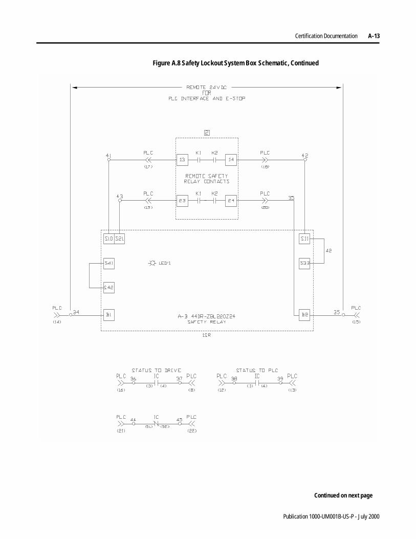
Figure A.8 Safety Lockout System Box Schematic, Continued
Continued on next page
Publication 1000-UM001B-US-P - July 2000

A-14 Certification Documentation
Figure A.9 Safety Lockout System Box Connection Diagram
Publication 1000-UM001B-US-P - July 2000

Certification Documentation A-15
Figure A.10 SLS Box with Pilz Relay, 30 A (Cat. No. 1000-NXSLSV30) and 85 A (Cat. No. 1000-NXSLSV85) Dimension Drawing
Publication 1000-UM001B-US-P - July 2000

A-16 Certification Documentation
Figure A.11 SLS Switch, NEMA Type 4 Stainless Dimension Drawing
Publication 1000-UM001B-US-P - July 2000

Certification Documentation A-17
Figure A.12 Safety Lockout System Switch Connection Diagram
Publication 1000-UM001B-US-P - July 2000

A-18 Certification Documentation
Figure A.13 LED Explanation
Publication 1000-UM001B-US-P - July 2000

Certification Documentation A-19
Table A.F LED Explanation
Item Description Indicator Explanation
1 Power Supply LED DC on when 120V is applied
2 Control Transformer Sec. Fuse
Blown Fuse
On when fuse is blown
3 Control Transformer (2) Pri. Fuses
Blown Fuse
On when fuse is blown
4 Safety Relay 1SR LED • POWER on when 24V DC is applied• CH1 on when circuit S10 to S11 is closed• CH2 on when circuit S21 to B2 is closed• K1 on when internal relay K1 is energized• K2 on when internal relay K2 is energized
5 Safety Relay SR LED • POWER on when 24V DC is applied• CH1 on when circuit S10 to S11 is closed
because all SLS switches are in the ON position
• CH2 on when circuit S10 to S11 is closed because all SLS switches are in the ON position
• K1 on when internal relay K1 is energized• K2 on when internal relay K2 is energized
6 Pilz Relay PVSR LED • POWER on when 24V DC is applied• VL1-L2 on voltage L1 to L2 is above 10V• VL2-L3 on voltage L2 to L3 is above 10V• VL1-L3 on voltage L1 to L3 is above 10V• VL1-N on voltage L1 to ground is above 10V• VL2-N on voltage L2 to ground is above 10V• VL3-N on voltage L3 to ground is above 10V• SYSTEM FAILURE on when one of the eight
voltage sensing connections is open or there is an internal fault in the PU3Z
• VOLTAGE HAZARD on when measured voltage is greater than 10V
7 ++ Terminal Block LED On when the timer contact is closed
8 – Terminal Block LED On when the 24V DC power supply output is on
9 12 Terminal Block LED On when IC and 1CR are off, PVSR output is closed, and an SLS switch is off
10 Timing Relay TR LED On when time delay is complete and output N.O. contact is closed
Publication 1000-UM001B-US-P - July 2000

A-20 Certification Documentation
Notes:
Publication 1000-UM001B-US-P - July 2000

Appendix B
References
A. NFPA 70E 1995 edition, NFPA 79 1997 edition
B. IEC 947, 60204-1, 954-1
1 Publication 1000-UM001B-US-P - July 2000

B-2 References
Notes:
Publication 1000-UM001B-US-P - July 2000

References B-3
Notes:
Publication 1000-UM001B-US-P - July 2000

B-4 References
Notes:
Publication 1000-UM001B-US-P - July 2000

Back Cover

Publication 1000-UM001B-US-P - July 2000 2© 1999 Rockwell International Corporation. Printed in the U.S.A.