safety manager safety manual - certipedia€¦ · safety manager safety manual 1 the safety manual...
TRANSCRIPT

Safety Manager
Safety ManualEP-SM.MAN.6283
Issue 1.0
20 February 2013
Release 151
ii
Notice
This document contains Honeywell proprietary information. Information contained herein is to be used solely for the purpose submitted, and no part of this document or its contents shall be reproduced, published, or disclosed to a third party without the express permission of Honeywell Safety Management Systems.
While this information is presented in good faith and believed to be accurate, Honeywell disclaims the implied warranties of merchantability and fitness for a purpose and makes no express warranties except as may be stated in its written agreement with and for its customer.
In no event is Honeywell liable to anyone for any direct, special, or consequential damages. The information and specifications in this document are subject to change without notice.
Specific products described in this document are covered by U.S. Patent Nos. D514075, D518003, D508469, D516047, D519470, D518450, D518452, D519087 and any foreign patent equivalents.
Copyright 2012 – Honeywell Safety Management Systems, a division of Honeywell Aerospace B.V.
Honeywell trademarks
Experion PKS®, PlantScape®, SafeBrowse®, TotalPlant® and TDC 3000® are U.S. registered trademarks of Honeywell International Inc.
Other trademarks
Microsoft and SQL Server are either registered trademarks or trademarks of Microsoft Corporation in the United States and/or other countries.
Trademarks that appear in this document are used only to the benefit of the trademark owner, with no intention of trademark infringement.
Document Release Issue Date
EP-SM.MAN.6283 151 1.0 February 2013

iii
Conventions
Symbols
The following symbols are used in Safety Manager documentation:
Attention
This symbol is used for information that emphasizes or supplements important points of the main text.
Tip
This symbol is used for useful, but not essential, suggestions.
Note
This symbol is used to emphasize or supplement important points of the main text.
Caution
This symbol warns of potential damage, such as corruption of the database.
Warning
This symbol warns of potentially hazardous situations, which, if not avoided, could result in serious injury or death.
ESD
This symbol warns for danger of an electro-static discharge to which equipment may be sensitive.

iv
Fonts
The following fonts are used in Safety Manager documentation:
Emphasis
• “... inform the reader on how to perform the task in terms of...”
• “...see the Overview Guide”
Emphasised text is used to:
• emphasise important words in the text,
• identify document titles.
Label
“The Advanced tab of the Properties dialog has..”
This font is used to identify labels and titles of (popup) dialogs.
Labels are used for Dialog box labels, menu items, names of properties, and so on.
Steps
Take the following steps:
1. Create a plant and set its properties.
2. ....
This font is used to identify steps.
Steps indicate the course of action that must be adhered to, to achieve a certain goal.
User Variable
..create the My Projects folder and store the readme.txt file here.
..press the Tab key..
Next press Enter to..
This font is used to:
1. identify a user variable, a filename, an object or view.
2. highlight the keys the user should press on the keyboard.
User variable is a variable, an object or a view that the reader can call-up to view or to manipulate.
Value
“Low is the fault reaction state for digital inputs and digital outputs.”
This font is used to indicate a value.
Value is a variable that the reader must resolve by choosing a pre-defined state.
Variable
“The syntax is: filename [-s] [-p]“
This font is used to identify a variable.
Variables are used in syntax and code examples.
http://www.honeywellsms.com This font is used to identify a URL, directing a reader to a website that can be referred to.

Safety Manager Safety Manual v
Contents
1 The Safety Manual 1Content of Safety Manual . . . . . . . . . . . . . . . . . . . . . . . . . . . . . . . . . . . . . . . . . . . . . . . . . . . . . . . 1
References . . . . . . . . . . . . . . . . . . . . . . . . . . . . . . . . . . . . . . . . . . . . . . . . . . . . . . . . . . . . . 2Basic skills and knowledge . . . . . . . . . . . . . . . . . . . . . . . . . . . . . . . . . . . . . . . . . . . . . . . . . . . . . . 3
Prerequisite skills. . . . . . . . . . . . . . . . . . . . . . . . . . . . . . . . . . . . . . . . . . . . . . . . . . . . . . . . 3Training . . . . . . . . . . . . . . . . . . . . . . . . . . . . . . . . . . . . . . . . . . . . . . . . . . . . . . . . . . . . . . . 3
Safety standards for Process & Equipment Under Control (PUC, EUC) . . . . . . . . . . . . . . . . . . . 4Safety Integrity level (SIL) . . . . . . . . . . . . . . . . . . . . . . . . . . . . . . . . . . . . . . . . . . . . . . . . 4Application design conform IEC 61131-3. . . . . . . . . . . . . . . . . . . . . . . . . . . . . . . . . . . . . 4The IEC 61508 and IEC 61511 standards . . . . . . . . . . . . . . . . . . . . . . . . . . . . . . . . . . . . . 5
2 Safety Manager functions, architectures and standards 9Safety Manager functions . . . . . . . . . . . . . . . . . . . . . . . . . . . . . . . . . . . . . . . . . . . . . . . . . . . . . . . 9Safety Manager basic architectures . . . . . . . . . . . . . . . . . . . . . . . . . . . . . . . . . . . . . . . . . . . . . . . . 9
Dual Modular Redundant (DMR) architecture . . . . . . . . . . . . . . . . . . . . . . . . . . . . . . . . 10Quadruple Modular Redundant (QMR) architecture . . . . . . . . . . . . . . . . . . . . . . . . . . . 11Watchdog architecture in mixed IO configurations - QMR architecture . . . . . . . . . . . . 12Safety Manager A.R.T. . . . . . . . . . . . . . . . . . . . . . . . . . . . . . . . . . . . . . . . . . . . . . . . . . . 13
Certification. . . . . . . . . . . . . . . . . . . . . . . . . . . . . . . . . . . . . . . . . . . . . . . . . . . . . . . . . . . . . . . . . 14Standards compliance . . . . . . . . . . . . . . . . . . . . . . . . . . . . . . . . . . . . . . . . . . . . . . . . . . . . . . . . . 16
3 Safety Manager fault detection and reaction 21Introduction . . . . . . . . . . . . . . . . . . . . . . . . . . . . . . . . . . . . . . . . . . . . . . . . . . . . . . . . . . . . . . . . . 21
Diagnostic Test Interval. . . . . . . . . . . . . . . . . . . . . . . . . . . . . . . . . . . . . . . . . . . . . . . . . . 22Controller configurations and states . . . . . . . . . . . . . . . . . . . . . . . . . . . . . . . . . . . . . . . . 22Fault Reaction and IO states . . . . . . . . . . . . . . . . . . . . . . . . . . . . . . . . . . . . . . . . . . . . . . 23Shutdown by application or manual intervention . . . . . . . . . . . . . . . . . . . . . . . . . . . . . . 24
Fault detection and reaction of the system . . . . . . . . . . . . . . . . . . . . . . . . . . . . . . . . . . . . . . . . . 25SM Controller faults . . . . . . . . . . . . . . . . . . . . . . . . . . . . . . . . . . . . . . . . . . . . . . . . . . . . . . . . . . 28
QPP faults . . . . . . . . . . . . . . . . . . . . . . . . . . . . . . . . . . . . . . . . . . . . . . . . . . . . . . . . . . . . 28USI faults. . . . . . . . . . . . . . . . . . . . . . . . . . . . . . . . . . . . . . . . . . . . . . . . . . . . . . . . . . . . . 30BKM faults . . . . . . . . . . . . . . . . . . . . . . . . . . . . . . . . . . . . . . . . . . . . . . . . . . . . . . . . . . . 30PSU faults . . . . . . . . . . . . . . . . . . . . . . . . . . . . . . . . . . . . . . . . . . . . . . . . . . . . . . . . . . . . 31Communication faults . . . . . . . . . . . . . . . . . . . . . . . . . . . . . . . . . . . . . . . . . . . . . . . . . . . 31
SM universal IO module faults . . . . . . . . . . . . . . . . . . . . . . . . . . . . . . . . . . . . . . . . . . . . . . . . . . 33Universal IO module faults . . . . . . . . . . . . . . . . . . . . . . . . . . . . . . . . . . . . . . . . . . . . . . . 33
SM chassis IO faults . . . . . . . . . . . . . . . . . . . . . . . . . . . . . . . . . . . . . . . . . . . . . . . . . . . . . . . . . . 35

Contents
vi Release 151, Issue 1.0
Digital input faults (chassis based) . . . . . . . . . . . . . . . . . . . . . . . . . . . . . . . . . . . . . . . . . 35Analog input faults (chassis based) . . . . . . . . . . . . . . . . . . . . . . . . . . . . . . . . . . . . . . . . . 36Digital output faults (chassis based) . . . . . . . . . . . . . . . . . . . . . . . . . . . . . . . . . . . . . . . . 37Analog output faults (chassis based) . . . . . . . . . . . . . . . . . . . . . . . . . . . . . . . . . . . . . . . . 38
SM universal IO channel faults . . . . . . . . . . . . . . . . . . . . . . . . . . . . . . . . . . . . . . . . . . . . . . . . . . 39Digital input faults (remote) . . . . . . . . . . . . . . . . . . . . . . . . . . . . . . . . . . . . . . . . . . . . . . 39Analog input faults (remote) . . . . . . . . . . . . . . . . . . . . . . . . . . . . . . . . . . . . . . . . . . . . . . 40Digital output faults (remote) . . . . . . . . . . . . . . . . . . . . . . . . . . . . . . . . . . . . . . . . . . . . . 40Analog output faults (remote) . . . . . . . . . . . . . . . . . . . . . . . . . . . . . . . . . . . . . . . . . . . . . 41
Compare error handling . . . . . . . . . . . . . . . . . . . . . . . . . . . . . . . . . . . . . . . . . . . . . . . . . . . . . . . 41IO compare errors and system response . . . . . . . . . . . . . . . . . . . . . . . . . . . . . . . . . . . . . 42Compare error detection and synchronization. . . . . . . . . . . . . . . . . . . . . . . . . . . . . . . . . 43
Calculation errors . . . . . . . . . . . . . . . . . . . . . . . . . . . . . . . . . . . . . . . . . . . . . . . . . . . . . . . . . . . . 46
4 Safety Manager special functions 47On-line modification . . . . . . . . . . . . . . . . . . . . . . . . . . . . . . . . . . . . . . . . . . . . . . . . . . . . . . . . . 47SafeNet communication . . . . . . . . . . . . . . . . . . . . . . . . . . . . . . . . . . . . . . . . . . . . . . . . . . . . . . 49
Networks . . . . . . . . . . . . . . . . . . . . . . . . . . . . . . . . . . . . . . . . . . . . . . . . . . . . . . . . . . . . . 49Protocol versus response time . . . . . . . . . . . . . . . . . . . . . . . . . . . . . . . . . . . . . . . . . . . . . 49
Reset . . . . . . . . . . . . . . . . . . . . . . . . . . . . . . . . . . . . . . . . . . . . . . . . . . . . . . . . . . . . . . . . . . . . . . 51System response towards a safety related reset. . . . . . . . . . . . . . . . . . . . . . . . . . . . . . . . 52
Simulation mode . . . . . . . . . . . . . . . . . . . . . . . . . . . . . . . . . . . . . . . . . . . . . . . . . . . . . . . . . . . . . 53
5 General guidelines for TÜV-approved applications 55General . . . . . . . . . . . . . . . . . . . . . . . . . . . . . . . . . . . . . . . . . . . . . . . . . . . . . . . . . . . . . . . . . . . . 55F&G applications . . . . . . . . . . . . . . . . . . . . . . . . . . . . . . . . . . . . . . . . . . . . . . . . . . . . . . . . . . . . 59
List of abbreviations 61

Safety Manager Safety Manual 1
1The Safety Manual
Content of Safety ManualThe Safety Manual is a reference guide providing detailed information regarding safety aspects in Safety Manager.
A reference guide is a Safety Manager related guide and does not describe tasks in terms of how to perform the task in terms of steps to follow. A reference guide can provide input to support decisions required to achieve a certain objective.
Guide subjects
Safety Manual • “Safety Manager functions, architectures and standards” on page 9
• “Safety Manager fault detection and reaction” on page 21
• “Safety Manager special functions” on page 47
• “General guidelines for TÜV-approved applications” on page 55

1 – The Safety Manual
2 Release 151, Issue 1.0
ReferencesThe following guides may be required as reference materials:
Guide Description
The Overview Guide This guide describes the general knowledge required, the basic functions of, and the tasks related to Safety Manager.
The Planning and Design Guide
This guide describes the tasks related to planning and designing a Safety Manager project.
The Installation and Upgrade Guide
This guide describes the tasks related to installing, replacing and upgrading hardware and software as part of a Safety Manager project.
The Troubleshooting and Maintenance Guide
This guide describes the tasks related to troubleshooting and maintaining Safety Manager.
The System Administration Guide
This guide describes the task related to administrating the computer systems used in a Safety Manager project.
The Hardware Reference This guide specifies the hardware components that build a Safety Manager project.
The Withdrawn Hardware Reference
This guide specifies all withdrawn hardware components and identifies alternatives for maintaining Safety Manager projects containing withdrawn hardware.
The Software Reference This guide specifies the software functions that build a Safety Manager project and contains guidelines on how to operate them.
The On-line Modification Guide
This guide describes the theory, steps and tasks related to upgrading Safety Builder and embedded software and modifying an application online in a redundant Safety Manager.

Basic skills and knowledge
Safety Manager Safety Manual 3
Basic skills and knowledgeBefore performing tasks related to Safety Manager you need to:
• Understand basic Safety Manager concepts as explained in the Overview Guide and the Glossary.
• Have a thorough understanding of the Safety Manual.
• Have had appropriate training related to Safety Manager that certifies you for your tasks (see the Planning and Design Guide).
Prerequisite skillsWhen you perform tasks related to Safety Manager, it is assumed that you have appropriate knowledge of:
• Site procedures
• The hardware and software you are working with. These may i.e. be: computers, printers, network components, Controller and Station software.
• Microsoft Windows operating systems.
• Programmable logic controllers (PLCs).
• Applicable safety standards for Process & Equipment Under Control.
• Application design conform IEC 61131-3.
• The IEC 61508 and IEC 61511 standards.
This guide assumes that you have a basic familiarity with the process(es) connected to the equipment under control and that you have a complete understanding of the hazard and risk analysis.
TrainingMost of the skills mentioned above can be achieved by appropriate training. For more information, contact your Honeywell SMS representative or see:
• http://www.automationcollege.com.

1 – The Safety Manual
4 Release 151, Issue 1.0
Safety standards for Process & Equipment Under Control (PUC, EUC)
Safety Integrity level (SIL)The IEC 61508 standard specifies 4 levels of safety performance for safety functions. These are called safety integrity levels. Safety integrity level 1 (SIL1) is the lowest level of safety integrity, and safety integrity level 4 (SIL4) the highest level. If the level is below SIL1, the IEC 61508 and IEC 61511 do not apply.
Safety Manager can be used for processing multiple SIFs simultaneously demanding a SIL1 up to and including SIL3.
To achieve the required safety integrity level for the E/E/PE safety-related systems, an overall safety life cycle is adopted as the technical framework (as defined in IEC 61508).
Application design conform IEC 61131-3The IEC 61131 standard defines, as a minimum set, the basic programming elements, syntactic and semantic rules for the most commonly used programming languages, including graphical languages of:
• Ladder Diagram,
• Functional Block Diagram and,
• Textual languages of Instruction List and structured Text;
For more information see the IEC web site.
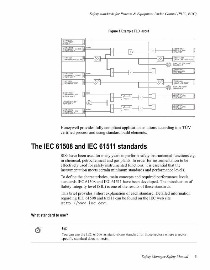
Figure 1 on page 5 shows how Safety Manager uses the graphical programming method, based on Functional Block Diagram as defined by the IEC 61131-3.
Safety standards for Process & Equipment Under Control (PUC, EUC)
Safety Manager Safety Manual 5
Honeywell provides fully compliant application solutions according to a TÜV certified process and using standard build elements.
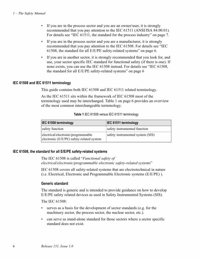
The IEC 61508 and IEC 61511 standardsSISs have been used for many years to perform safety instrumented functions e.g. in chemical, petrochemical and gas plants. In order for instrumentation to be effectively used for safety instrumented functions, it is essential that the instrumentation meets certain minimum standards and performance levels.
To define the characteristics, main concepts and required performance levels, standards IEC 61508 and IEC 61511 have been developed. The introduction of Safety Integrity level (SIL) is one of the results of these standards.
This brief provides a short explanation of each standard. Detailed information regarding IEC 61508 and 61511 can be found on the IEC web site http://www.iec.org.
What standard to use?
Figure 1 Example FLD layout
Tip:
You can use the IEC 61508 as stand-alone standard for those sectors where a sector specific standard does not exist.
1 – The Safety Manual
6 Release 151, Issue 1.0
• If you are in the process sector and you are an owner/user, it is strongly recommended that you pay attention to the IEC 61511 (ANSI/ISA 84.00.01). For details see “IEC 61511, the standard for the process industry” on page 7.
• If you are in the process sector and you are a manufacturer, it is strongly recommended that you pay attention to the IEC 61508. For details see “IEC 61508, the standard for all E/E/PE safety-related systems” on page 6.
• If you are in another sector, it is strongly recommended that you look for, and use, your sector specific IEC standard for functional safety (if there is one). If none exists, you can use the IEC 61508 instead. For details see “IEC 61508, the standard for all E/E/PE safety-related systems” on page 6
IEC 61508 and IEC 61511 terminology
This guide contains both IEC 61508 and IEC 61511 related terminology.
As the IEC 61511 sits within the framework of IEC 61508 most of the terminology used may be interchanged. Table 1 on page 6 provides an overview of the most common interchangeable terminology.
IEC 61508, the standard for all E/E/PE safety-related systems
The IEC 61508 is called “Functional safety of electrical/electronic/programmable electronic safety-related systems”
IEC 61508 covers all safety-related systems that are electrotechnical in nature (i.e. Electrical, Electronic and Programmable Electronic systems (E/E/PE) ).
Generic standard
The standard is generic and is intended to provide guidance on how to develop E/E/PE safety related devices as used in Safety Instrumented Systems (SIS).
The IEC 61508:
• serves as a basis for the development of sector standards (e.g. for the machinery sector, the process sector, the nuclear sector, etc.).
• can serve as stand-alone standard for those sectors where a sector specific standard does not exist.
Table 1 IEC 61508 versus IEC 61511 terminology
IEC 61508 terminology IEC 61511 terminology
safety function safety instrumented function
electrical/electronic/programmable electronic (E/E/PE) safety-related system
safety instrumented system (SIS)

Safety standards for Process & Equipment Under Control (PUC, EUC)
Safety Manager Safety Manual 7
SIL
IEC 61508 details the design requirements for achieving the required Safety Integrity Level (SIL).
The safety integrity requirements for each individual safety function may differ. The safety function and SIL requirements are derived from the hazard analysis and the risk assessment.
The higher the level of adapted safety integrity, the lower the likelihood of dangerous failure of the SIS.
This standard also addresses the safety-related sensors and final elements regardless of the technology used.
IEC 61511, the standard for the process industry
The IEC 61511 is called “Functional safety - Safety instrumented systems for the process industry sector”. It is also referred to as the ANSI/ISA 84.00.01.
This standard addresses the application of SISs for the process industries. It requires a process hazard and risk assessment to be carried out, to enable the specification for SISs to be derived. In this standard a SIS includes all components and subsystems necessary to carry out the safety instrumented function from sensor(s) to final element(s).
The standard is intended to lead to a high level of consistency in underlying principles, terminology and information within the process industries. This should have both safety and economic benefits.
The IEC 61511 sits within the framework of IEC 61508.
Need to know more?
For more information regarding, or help on, implementing or determining, the applied safety standards for your plant/process please contact your Honeywell affiliate. Our Safety Consultants can help you to e.g.:
• perform a hazard risk analysis
• determine the SIL requirements
• design the Safety Instrumented System
• validate and verify the design
• train your local safety staff

1 – The Safety Manual
8 Release 151, Issue 1.0
Safety Manager Safety Manual 9
2Safety Manager functions, architectures and standards
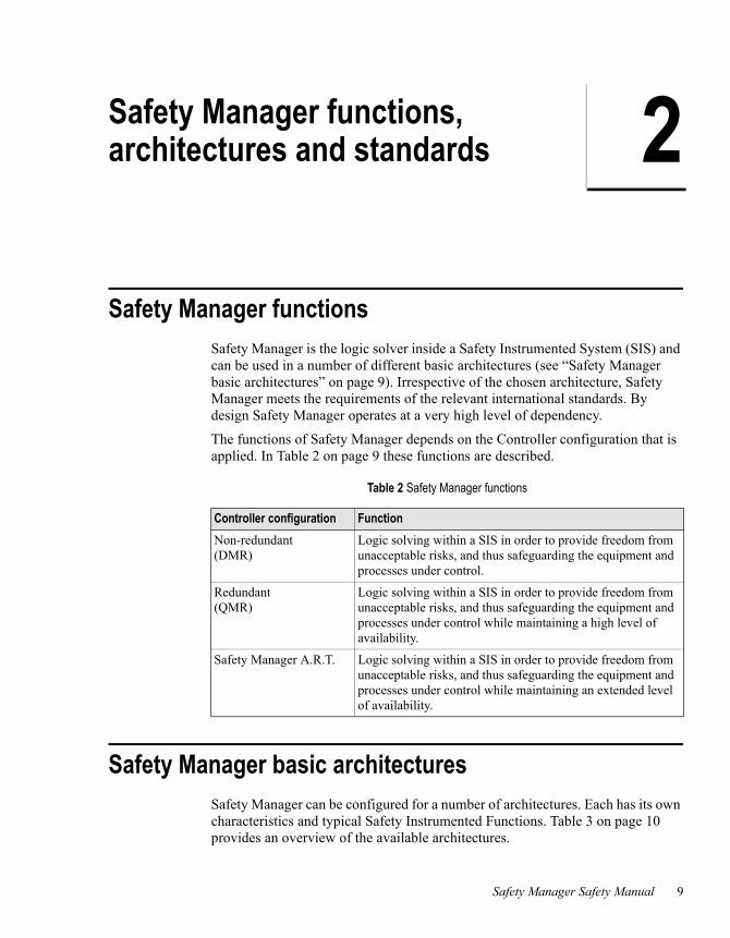
Safety Manager functionsSafety Manager is the logic solver inside a Safety Instrumented System (SIS) and can be used in a number of different basic architectures (see “Safety Manager basic architectures” on page 9). Irrespective of the chosen architecture, Safety Manager meets the requirements of the relevant international standards. By design Safety Manager operates at a very high level of dependency.
The functions of Safety Manager depends on the Controller configuration that is applied. In Table 2 on page 9 these functions are described.
Safety Manager basic architecturesSafety Manager can be configured for a number of architectures. Each has its own characteristics and typical Safety Instrumented Functions. Table 3 on page 10 provides an overview of the available architectures.
Table 2 Safety Manager functions
Controller configuration Function
Non-redundant (DMR)
Logic solving within a SIS in order to provide freedom from unacceptable risks, and thus safeguarding the equipment and processes under control.
Redundant (QMR)
Logic solving within a SIS in order to provide freedom from unacceptable risks, and thus safeguarding the equipment and processes under control while maintaining a high level of availability.
Safety Manager A.R.T. Logic solving within a SIS in order to provide freedom from unacceptable risks, and thus safeguarding the equipment and processes under control while maintaining an extended level of availability.

2 – Safety Manager functions, architectures and standards
10 Release 151, Issue 1.0
Dual Modular Redundant (DMR) architectureTypical applications of a Dual Modular Redundant (DMR) architecture are:
• Burner Management System
• Batch processing
• Machine protection
The DMR architecture provides 1oo2 voting in a non-redundant system. The DMR architecture with 1oo2 voting is based on dual-processor technology, and is characterized by a high level of self tests, diagnostics and fault tolerance. The DMR architecture is realized with a non-redundant Controller. A non-redundant architecture contains only one QPP, which contains redundant processors and memory with 1oo2 voting between the processors and memory.
In IO configurations, each path is primarily controlled by the Control Processor and an independent watchdog signal (see Figure 2 on page 10).
Table 3 Safety Manager architectures
Controller configuration IO configuration Remarks
Non-redundant (DMR)
Non-redundant DMR architecture; Supports SIF for SIL1, SIL2 and SIL3 applications.
Redundant (QMR)
Non-redundant
Redundant
Redundant and non-redundant
QMR architecture; Supports SIF for SIL1, SIL2 and SIL3 applications.
Safety Manager A.R.T. Non-redundant
Redundant
A.R.T. architecture; Supports SIF for SIL1, SIL2 and SIL3 applications.
Figure 2 Functional diagram: DMR architecture
Final Element
+Output
Interface
QPPControl
Processor
InputInterface
Watchdog signal
Sensor
xxyyy

Safety Manager Safety Manual 11
Quadruple Modular Redundant (QMR) architectureTypical applications of a QMR architecture are:
• process safeguarding applications for which continuous operation is essential.
The Quadruple Modular Redundant (QMR) architecture is based on 2oo4D voting, dual-processor technology in each QPP. This means that it is characterized by a ultimate level of self diagnostics and fault tolerance.
The QMR architecture is realized with a redundant Controller. This redundant architecture contains two QPPs, which results in quadruple redundancy making it fault tolerant for safety.
The 2oo4D voting is realized by combining 1oo2 voting of both CPUs and memory in each QPP, and 1oo2D voting between the two QPPs. Voting takes place on two levels: on a module level and between the QPPs.
In redundant IO configurations, each path is controlled by one of the Control Processors and an independent watchdog signal, which is controlled by the diagnostic software (see Figure 3 on page 11).
Furthermore, each Control Processor is able to switch off the output channels of the other Control Processor.
Figure 3 Functional diagram: QMR architecture
UniversalIO module
n2
UniversalIO module
n1
Final Element
Watchdog signal
OutputInterfaceQPP
ControlProcessor 2
InputInterface
+Output
Interface
QPPControl
Processor 1InputInterface
Sensor
xxyyy
2 – Safety Manager functions, architectures and standards
12 Release 151, Issue 1.0
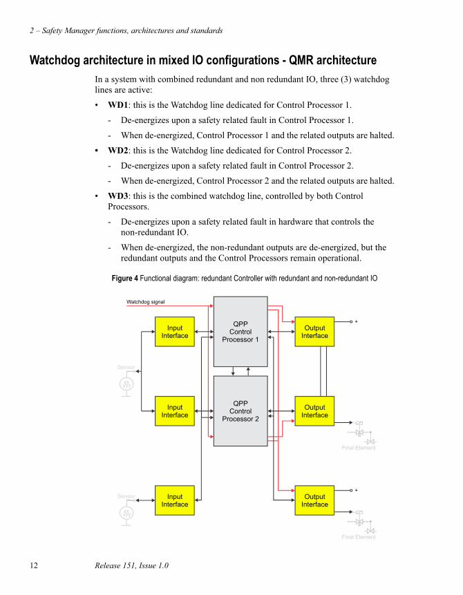
Watchdog architecture in mixed IO configurations - QMR architectureIn a system with combined redundant and non redundant IO, three (3) watchdog lines are active:
• WD1: this is the Watchdog line dedicated for Control Processor 1.
- De-energizes upon a safety related fault in Control Processor 1.
- When de-energized, Control Processor 1 and the related outputs are halted.
• WD2: this is the Watchdog line dedicated for Control Processor 2.
- De-energizes upon a safety related fault in Control Processor 2.
- When de-energized, Control Processor 2 and the related outputs are halted.
• WD3: this is the combined watchdog line, controlled by both Control Processors.
- De-energizes upon a safety related fault in hardware that controls the non-redundant IO.
- When de-energized, the non-redundant outputs are de-energized, but the redundant outputs and the Control Processors remain operational.
Figure 4 Functional diagram: redundant Controller with redundant and non-redundant IO
Final Element
+Output
InterfaceInput
InterfaceSensor
xxyyy
Final Element
Watchdog signal
OutputInterface
QPPControl
Processor 2
InputInterface
+Output
Interface
QPPControl
Processor 1
InputInterface
Sensor
xxyyy
Safety Manager Safety Manual 13
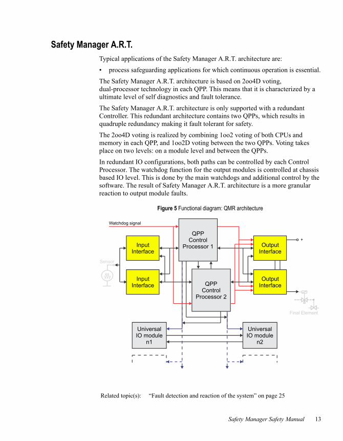
Safety Manager A.R.T.Typical applications of the Safety Manager A.R.T. architecture are:
• process safeguarding applications for which continuous operation is essential.
The Safety Manager A.R.T. architecture is based on 2oo4D voting, dual-processor technology in each QPP. This means that it is characterized by a ultimate level of self diagnostics and fault tolerance.
The Safety Manager A.R.T. architecture is only supported with a redundant Controller. This redundant architecture contains two QPPs, which results in quadruple redundancy making it fault tolerant for safety.
The 2oo4D voting is realized by combining 1oo2 voting of both CPUs and memory in each QPP, and 1oo2D voting between the two QPPs. Voting takes place on two levels: on a module level and between the QPPs.
In redundant IO configurations, both paths can be controlled by each Control Processor. The watchdog function for the output modules is controlled at chassis based IO level. This is done by the main watchdogs and additional control by the software. The result of Safety Manager A.R.T. architecture is a more granular reaction to output module faults.
Figure 5 Functional diagram: QMR architecture
Related topic(s): “Fault detection and reaction of the system” on page 25
UniversalIO module
n2
UniversalIO module
n1
Final Element
Watchdog signal
OutputInterfaceQPP
ControlProcessor 2
InputInterface
+Output
Interface
QPPControl
Processor 1InputInterface
Sensor
xxyyy

2 – Safety Manager functions, architectures and standards
14 Release 151, Issue 1.0
CertificationThe advantage of applying and complying to standards is obvious:
• International standards force companies to evaluate and develop their products and processes according a consistent and uniform way.
• Products certified conform these international standards guarantee a certain degree of quality and product reliability that other products lack.
Since functional safety is the core of the Safety Manager design, the system has been certified for use in safety applications all around the world. Safety Manager has been developed specifically to comply with the IEC61508 functional safety standards, and has been certified by TUV for use in SIL1 to SIL3 applications.
Safety Manager has also obtained certification in the United States for the ANSI/ISA S84.01 standard.
For a full list of all these and other certifications see “Certification” on page 14.
Certification
Safety Manager has been certified to comply with the following standards:
Lloyd’s Register — Safety Manager is certified for offshore and floating production facilities application use in environmental categories ENV1, ENV2 as per LR Type Approval System, Test Specification # 1, 2002
International Electrotechnical Commission (IEC) — The design and development of Safety Manager are compliant with IEC 61508 (as certified by TUV).
Instrument Society of America (ISA) — Certified to fulfill the requirements laid down in ANSI/ISA S84.01.
CE compliance — Complies with CE directives 2004/108/EEC (EMC) and 2006/95/EEC (Low Voltage), 2006/42/EEC (Machine Safety)
Certification
Safety Manager Safety Manual 15
European Committee for Standardization — CEN, CENELEC
TUV (Germany) — Certified to fulfill the requirements of SIL1, 2 and 3 safety equipment as defined in the following documents: IEC61508, IEC60664-3, EN50156, EN 54-2, EN50178, IEC 60068, IEC 61131-2, IEC 61131-3, IEC60204.
Canadian Standards Association (CSA) — Complies with the requirements of the following standards:
• CSA Standard C22.2 No. 0-M982 General Requirements – Canadian Electrical Code, Part II;
• CSA Standard C22.2 No. 142-M1987 for Process Control Equipment, including general Instructions up to No. 4 dated February 1989 (Reaffirmed 2004).
Underwriters Laboratories (UL) — Certified to fulfill the requirements of UL 508, UL 508A and ANSI/ISA S84.01.
Factory Mutual (FM) — Certified to fulfill the requirements of FM 3611 and FM3600 (non-incentive field wiring circuits for selected modules and installation in Class 1 Div 2 environments).
2 – Safety Manager functions, architectures and standards
16 Release 151, Issue 1.0
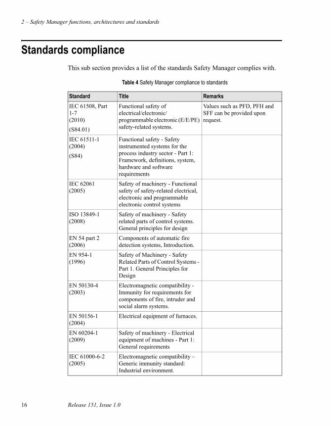
Standards complianceThis sub section provides a list of the standards Safety Manager complies with.
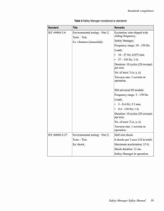
Table 4 Safety Manager compliance to standards
Standard Title Remarks
IEC 61508, Part 1-7 (2010)
(S84.01)
Functional safety of electrical/electronic/ programmable electronic (E/E/PE) safety-related systems.
Values such as PFD, PFH and SFF can be provided upon request.
IEC 61511-1 (2004)
(S84)
Functional safety - Safety instrumented systems for the process industry sector - Part 1: Framework, definitions, system, hardware and software requirements
IEC 62061 (2005)
Safety of machinery - Functional safety of safety-related electrical, electronic and programmable electronic control systems
ISO 13849-1 (2008)
Safety of machinery - Safety related parts of control systems. General principles for design
EN 54 part 2 (2006)
Components of automatic fire detection systems, Introduction.
EN 954-1 (1996)
Safety of Machinery - Safety Related Parts of Control Systems - Part 1. General Principles for Design
EN 50130-4 (2003)
Electromagnetic compatibility - Immunity for requirements for components of fire, intruder and social alarm systems.
EN 50156-1 (2004)
Electrical equipment of furnaces.
EN 60204-1 (2009)
Safety of machinery - Electrical equipment of machines - Part 1: General requirements
IEC 61000-6-2 (2005)
Electromagnetic compatibility – Generic immunity standard: Industrial environment.

Standards compliance
Safety Manager Safety Manual 17
IEC 61010-1 (2010)
Safety Requirements for Electrical Equipment for Measurement, Control and Laboratory Use, Part 1: General Requirements.
IEC 61131-2 (2007)
Programmable controllers. Part 2: Equipment requirements and tests.
IEC 61326-3-1 (2008)
Immunity requirements for safety related systems.
NFPA 72 (2010)
National Fire Alarm Code Handbook
NFPA 85 (2011)
Boiler and Combustions Systems Hazards Code
NFPA 86 (2011)
Standard for Ovens and Furnaces
UL 508 Industrial control equipment, seventeenth edition.
Underwriters Laboratories.
UL 508A (2001)
UL Standard for Safety Industrial Control Panels
Underwriters Laboratories.
FM3600, FM 3611
Class I, Division 2, Groups A, B, C & D
Class II, Division 2, Groups F & G
Electrical equipment for use in
• Class I, Division 2,
• Class II, Division 2, and
• Class III, Division 1 and 2, hazardous locations.
Factory Mutual Research.
Applies to the field wiring circuits of the following modules:
SDI-1624, SAI-0410, SAI-1620m, SDIL-1608 and SAO-0220m, and installation of the Controller in these environments.
CSA C22.2 Process control equipment. Industrial products.
Canadian Standards Association No. 142.
IEC 60068-1 (2004)
Basic environmental testing procedures.
IEC 60068-2-1 Cold test. (undervoltage)
Safety Manager; -5°C (23°F)
SM universal IO module; -40°C (-40°F)
16 hours; system in operation; reduced power supply voltage:
(–15%): U=20.4 Vdc or
(–10%): U=198 Vac.
Table 4 Safety Manager compliance to standards
Standard Title Remarks

2 – Safety Manager functions, architectures and standards
18 Release 151, Issue 1.0
IEC 60068-2-1 Cold test. (nominal)
Safety Manager; -10°C (14°F)
SM universal IO module; -45°C (-49°F)
16 hours; system in operation.
IEC 60068-2-2 Dry heat test. up to 70°C (158°F)
16 hours; system in operation; increased power supply voltage:
(+30%): U=31.2 Vdc or
(+10%): U=253 Vac.
IEC 60068-2-3 Test Ca: damp heat, steady state. 21 days at +40°C (104°F), 93% relative humidity; function test after cooling.
IEC 60068-2-3 Test Ca: damp heat, steady state. 96 hours at +40°C (104°F), 93% relative humidity; system in operation.
IEC 60068-2-14 Test Na: change of temperature – withstand test.
–25°C—+55°C (–13°F—+131°F), 12 hours, 95% relative humidity, recovery time: max. 2 hours.
IEC 60068-2-30 Test Db variant 2: cyclic damp heat test.
+25°C - +55°C (+77°F - +131°F), 7days, 80-100% relative humidity, recovery time: 1 - 2 hours.
Table 4 Safety Manager compliance to standards
Standard Title Remarks
Standards compliance
Safety Manager Safety Manual 19
IEC 60068-2-6 Environmental testing – Part 2:
Tests – Test.
Fc: vibration (sinusoidal).
Excitation: sine-shaped with sliding frequency;
Safety Manager:
Frequency range: 10 - 150 Hz.
Loads:
• 10 - 57 Hz; 0.075 mm.
• 57 - 150 Hz; 1 G.
Duration: 10 cycles (20 sweeps) per axis.
No. of axes: 3 (x, y, z).
Traverse rate: 1 oct/min in operation.
SM universal IO module
Frequency range: 3 - 150 Hz.
Loads:
• 3 - 8.4 Hz; 3.5 mm.
• 8.4 - 150 Hz; 1 G.
Duration: 10 cycles (20 sweeps) per axis.
No. of axes: 3 (x, y, z).
Traverse rate: 1 oct/min in operation.
IEC 60068-2-27 Environmental testing – Part 2:
Tests – Test.
Ea: shock.
Half sine shock.
6 shocks per 3 axes (18 in total).
Maximum acceleration: 15 G.
Shock duration: 11 ms.
Safety Manager in operation.
Table 4 Safety Manager compliance to standards
Standard Title Remarks

2 – Safety Manager functions, architectures and standards
20 Release 151, Issue 1.0

Safety Manager Safety Manual 21
3Safety Manager fault detection and reaction
IntroductionThe goal of fault detection and reaction is to detect and isolate faults that affect the safety of the process under control, within a time frame that is acceptable for the process.
Fault detection and reaction occurs at different levels. These levels are:
• system level,
• module level,
• channel level.
System level
Combinations of modules and IO faults are controlled at system level. Depending on the hardware and configuration of a system, the fault reaction to such combinations will be different. Distinction is made between these systems:
• Safety Manager,
• Safety Manager A.R.T.
For further details see:
• “Fault detection and reaction of the system” on page 25.
Module level
Faults at module level are controlled at controller level. Depending on the hardware and configuration of a system, the fault reaction is determined by the Control Processor and/or universal module(s).
For further details see the fault reaction table(s) in:
Note:
There is always a diagnostic alarm available upon detection of a fault.

3 – Safety Manager fault detection and reaction
22 Release 151, Issue 1.0
• “SM Controller faults” on page 28.
• “SM universal IO module faults” on page 33.
Channel level
Faults at channel level are controlled at controller level. Depending on the hardware and configuration of a system, the fault reaction is determined by the Control Processor and/or universal module(s).
For further details see the fault reaction table(s) in:
• “SM chassis IO faults” on page 35.
• “SM universal IO module faults” on page 33.
Diagnostic Test IntervalThe Diagnostic Test interval (DTI) is the time in which detection and isolation of faults takes place. The DTI must be set to a value that is acceptable for the process, such as the Process Safety Time (PST). These values can be obtained from hazard analysis reports.
Controller configurations and states
Controller configurations
In this chapter distinction is made between Non redundant Controllers and Redundant Controllers. A Non redundant Controller has one Control Processor (CP); the response of the CP is automatically the response of the controller. A Redundant Controller has two CPs; the response of one of the CPs does not necessarily affect the safety related functioning of the controller.
Control Processor states
A Control Processor (CP) can have many states. For fault detection and reaction the following states are relevant.
Note:
Safety Manager can have both non redundant controllers and redundant controllers.
Safety Manager A.R.T. only has redundant controllers.
Attention:
The states described below are presented on the display of the relevant QPP, while the key switch of that QPP is in the RUN position.
Safety Manager Safety Manual 23
• Running (without faults); CP is fully functional and executes the application.
• Running with Flt (with faults); CP executes the application but the controller detected one or more faults (e.g. open loop or a hardware fault).
• Halt; CP does not execute the application.
The applicable CP state can be read from the User Interface Display located on each Control Processor and from the diagnostic screens available on Experion™ and Safety Stations.
Fault Reaction and IO statesThe Fault Reaction (FR) state of each IO point is the predetermined state or action the point assumes in case of faults.
• For normally energized safety related applications, like ESD applications, the predefined safe fault reaction state is de-energized or Low.
• For normally de-energized safety related applications, like FGS applications, the safe fault reaction state for inputs is energized or High / Top Scale.
Fault reaction and IO states are explained below:
Fault reaction
The reaction to faults in the Controller, application and/or IO.
• The fault reaction towards Controller and/or application faults is fixed.
• The fault reaction to IO faults can be configured on a point or module level; it should be customized to the application for which Safety Manager is used.
IO states
From a system point of view, IO can have either the healthy state, the de-energized state or the fault reaction state.
• When healthy, the IO is active and has the application value applied.
• When de-energized, the IO is de-activated (as if no power was supplied).
• When the fault reaction state is applied, the IO responds according to a predefined fault condition (fault reaction).
• When forced, the force value is applied.
Repair timer
Note:
The repair timer setting must be based on a hardware reliability analysis which includes MTTR figures.
3 – Safety Manager fault detection and reaction
24 Release 151, Issue 1.0
All configurations of Safety Manager are single fault tolerant to faults that affect safety. By applying a secondary means Safety Manager is able to bring a process to a safe state, regardless the fault.
By default, Safety Manager is configured to isolate the faulty part of a subsystem to guarantee continued safe operation of the EUC. In systems with a redundant Control Processor (CP) a fault in a susbsytem of one of the CPs has no effect on the safeguarded process. Continuous safeguarding and availability is maintained.
A configurable repair timer is started for the relevant CP on certain fault conditions. Within the remaining time the faulty part can be repaired. If the timer is allowed to reach zero, or another fault that affects safety occurs, that Control Processor halts.
It is strongly advised to apply this feature of Safety Manager to meet the requirements of applicable standards. However, the user can choose to configure Safety Manager differently to meet his own specific requirements.
Shutdown by application or manual interventionBy design, Safety Manager is configured to meet the requirements of applicable international standards. In case local and/or customer requirements demand an even more stringent system response, Safety Manager offers two additional features for such situations. These features are:
• A shutdown via the application software; to achieve this Safety Manager alarm markers can be applied.
• A manual shutdown can be realized via the shutdown (SD) input of the SM Controller or the SM universal IO modules. With aid of the SD input a tested, hard wired connection can be used. The SD input is accessible via the SD loop connector at the back of the CP chassis or channel 32 of the SM universal IO module.
Attention:1. Breaking the SD loop of the CP will cause Safety Manager to stop!2. Breaking the SD loop of the SM universal IO module will cause the SM universal IO
module to stop!
Fault detection and reaction of the system
Safety Manager Safety Manual 25
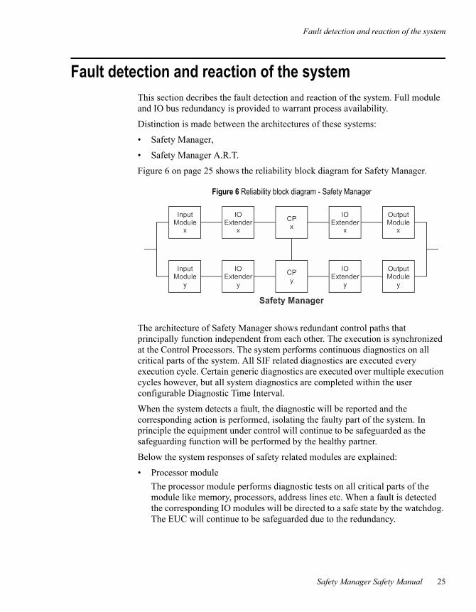
Fault detection and reaction of the systemThis section decribes the fault detection and reaction of the system. Full module and IO bus redundancy is provided to warrant process availability.
Distinction is made between the architectures of these systems:
• Safety Manager,
• Safety Manager A.R.T.
Figure 6 on page 25 shows the reliability block diagram for Safety Manager.
The architecture of Safety Manager shows redundant control paths that principally function independent from each other. The execution is synchronized at the Control Processors. The system performs continuous diagnostics on all critical parts of the system. All SIF related diagnostics are executed every execution cycle. Certain generic diagnostics are executed over multiple execution cycles however, but all system diagnostics are completed within the user configurable Diagnostic Time Interval.
When the system detects a fault, the diagnostic will be reported and the corresponding action is performed, isolating the faulty part of the system. In principle the equipment under control will continue to be safeguarded as the safeguarding function will be performed by the healthy partner.
Below the system responses of safety related modules are explained:
• Processor module
The processor module performs diagnostic tests on all critical parts of the module like memory, processors, address lines etc. When a fault is detected the corresponding IO modules will be directed to a safe state by the watchdog. The EUC will continue to be safeguarded due to the redundancy.
Figure 6 Reliability block diagram - Safety Manager
3 – Safety Manager fault detection and reaction
26 Release 151, Issue 1.0
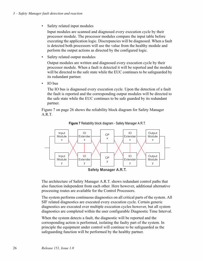
• Safety related input modules
Input modules are scanned and diagnosed every execution cycle by their processor module. The processor modules compare the input table before executing the application logic. Discrepancies will be diagnosed. When a fault is detected both processors will use the value from the healthy module and perform the output actions as directed by the configured logic.
• Safety related output modules
Output modules are written and diagnosed every execution cycle by their processor module. When a fault is detected it will be reported and the module will be directed to the safe state while the EUC continues to be safeguarded by its redundant partner.
• IO bus
The IO bus is diagnosed every execution cycle. Upon the detection of a fault the fault is reported and the corresponding output modules will be directed to the safe state while the EUC continues to be safe guarded by its redundant partner.
Figure 7 on page 26 shows the reliability block diagram for Safety Manager A.R.T.
The architecture of Safety Manager A.R.T. shows redundant control paths that also function independent from each other. Here however, additional alternative processing routes are available for the Control Processors.
The system performs continuous diagnostics on all critical parts of the system. All SIF related diagnostics are executed every execution cycle. Certain generic diagnostics are executed over multiple execution cycles however, but all system diagnostics are completed within the user configurable Diagnostic Time Interval.
When the system detects a fault, the diagnostic will be reported and the corresponding action is performed, isolating the faulty part of the system. In principle the equipment under control will continue to be safeguarded as the safeguarding function will be performed by the healthy partner.
Figure 7 Reliability block diagram - Safety Manager A.R.T.

Fault detection and reaction of the system
Safety Manager Safety Manual 27
Below the system responses of safety related modules are explained:
• Processor module
The processor module performs diagnostic tests on all critical parts of the module like memory, processors, address lines etc. When a fault is detected the processor module will go to a safe state. The EUC will continue to be safeguarded due to the redundancy.
• Safety related input modules
Input modules are scanned and diagnosed every execution cycle by their processor module. The processor modules compare the input table before executing the application logic. Discrepancies will be diagnosed. When a fault is detected both processors will use the value from the healthy module and perform the output actions as directed by the configured logic.
• Safety related output modules
Output modules are written and diagnosed every execution cycle by their processor module. When a fault is detected it will be reported and the module will be directed to the safe state while the EUC continues to be safeguarded by its redundant partner.
• IO bus
The IO bus of the A.R.T. system is multi fault tolerant, allowing multiple faults at the same time while continuing the safeguarding of the equipment under control.The IO bus is diagnosed every execution cycle. Upon detection of a fault the fault is reported and the module is directed to the safe state. The corresponding processor module will use the remaining healthy module.
3 – Safety Manager fault detection and reaction
28 Release 151, Issue 1.0
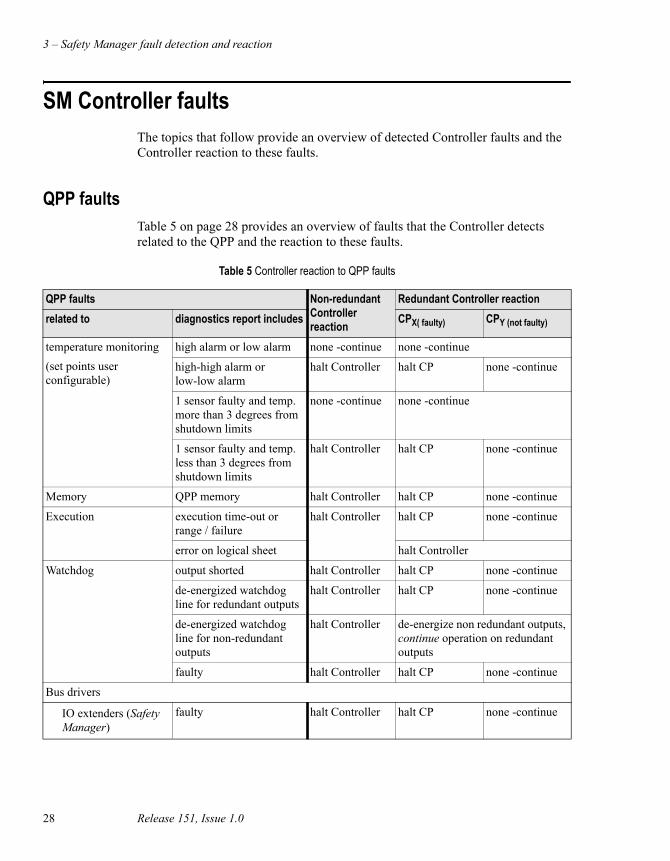
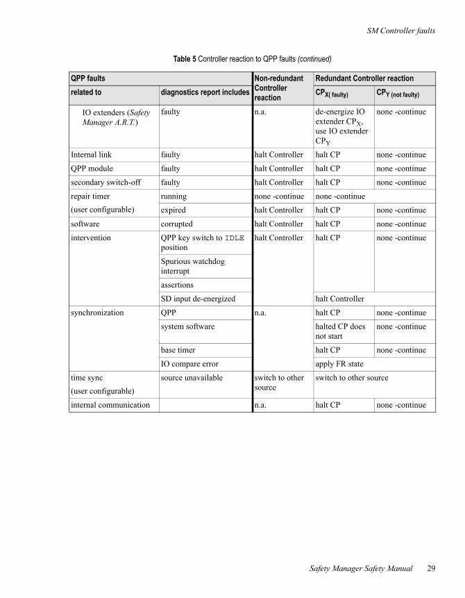
SM Controller faultsThe topics that follow provide an overview of detected Controller faults and the Controller reaction to these faults.
QPP faultsTable 5 on page 28 provides an overview of faults that the Controller detects related to the QPP and the reaction to these faults.
Table 5 Controller reaction to QPP faults
QPP faults Non-redundant Controller reaction
Redundant Controller reaction
related to diagnostics report includes CPX( faulty) CPY (not faulty)
temperature monitoring
(set points user configurable)
high alarm or low alarm none -continue none -continue
high-high alarm or low-low alarm
halt Controller halt CP none -continue
1 sensor faulty and temp. more than 3 degrees from shutdown limits
none -continue none -continue
1 sensor faulty and temp. less than 3 degrees from shutdown limits
halt Controller halt CP none -continue
Memory QPP memory halt Controller halt CP none -continue
Execution execution time-out or range / failure
halt Controller halt CP none -continue
error on logical sheet halt Controller
Watchdog output shorted halt Controller halt CP none -continue
de-energized watchdog line for redundant outputs
halt Controller halt CP none -continue
de-energized watchdog line for non-redundant outputs
halt Controller de-energize non redundant outputs, continue operation on redundant outputs
faulty halt Controller halt CP none -continue
Bus drivers
IO extenders (Safety Manager)
faulty halt Controller halt CP none -continue
SM Controller faults
Safety Manager Safety Manual 29
IO extenders (Safety Manager A.R.T.)
faulty n.a. de-energize IO extender CPX, use IO extender CPY
none -continue
Internal link faulty halt Controller halt CP none -continue
QPP module faulty halt Controller halt CP none -continue
secondary switch-off faulty halt Controller halt CP none -continue
repair timer
(user configurable)
running none -continue none -continue
expired halt Controller halt CP none -continue
software corrupted halt Controller halt CP none -continue
intervention QPP key switch to IDLE position
halt Controller halt CP none -continue
Spurious watchdog interrupt
assertions
SD input de-energized halt Controller
synchronization QPP n.a. halt CP none -continue
system software halted CP does not start
none -continue
base timer halt CP none -continue
IO compare error apply FR state
time sync
(user configurable)
source unavailable switch to other source
switch to other source
internal communication n.a. halt CP none -continue
Table 5 Controller reaction to QPP faults (continued)
QPP faults Non-redundant Controller reaction
Redundant Controller reaction
related to diagnostics report includes CPX( faulty) CPY (not faulty)

3 – Safety Manager fault detection and reaction
30 Release 151, Issue 1.0
USI faultsTable 6 on page 30 provides an overview of detected faults in relation to the USI and the response to these faults.
A fault in the USI also means that the communication channels of that USI do not communicate anymore.
BKM faultsTable 7 on page 30 provides an overview of faults that can be detected in relation to the BKM and the response to these faults.
Table 6 Controller response to USI faults
USI faults Non redundant Controller response
Redundant Controller response
related to diagnostics report includes
CPX( faulty) CPY (not faulty)
Memory USI module apply FR state to affected COM, FSC & universal IO points.
use values from CPY for affected COM, FSC & universal IO points.1
1 If values are not available via CPY apply FR state to affected COM, FSC & universal IO points.
none
Execution
communication USI module
module faulty USI module
synchronization system software
software corrupted
Table 7 Controller response to BKM faults
BKM faults Non redundant Controller response
Redundant Controller response
related to diagnostics report includes CPX( faulty) CPY (not faulty)
key switch input compare error (reset key switch)
none -continue none -continue
input compare error (force key switch)
module faulty BKM module none -continue none -continue
battery faulty / low none -continue none -continue
lifetime expired
transport switch

SM Controller faults
Safety Manager Safety Manual 31
PSU faultsTable 8 on page 31 provides an overview of faults that can be detected in relation to the PSU and the response to these faults.
Communication faults
Table 9 on page 31 provides an overview of faults that can be detected in relation to communication and the response to these faults.
Table 8 Controller response to PSU faults
PSU faults Non redundant Controller response
Redundant Controller response
related to diagnostics report includes CPX( faulty) CPY (not faulty)
Voltage monitoring spurious watchdog interrupt halt Controller halt CP none -continue
module faulty PSU module
Note
Please note that a fault in the communication links may be caused by USI modules.
Table 9 Controller response to communication faults
communication faults Non redundant communication or “shared CP”
Controller response1
Redundant communication
Controller response
Related to Diagnostic message reports
CPX(faulty) CPY(not faulty
broken link communication fault2
apply FR state to affected COM, FSC & universal IO points of that channel
if channel belongs to active clock source, switch to other clock source
continue communication via healthy link3
none -continue
wrong protocol assigned
time-out
too many data requests USI module faulty apply FR state to affected COM, FSC & universal IO points of that USI
use values from CPY for affected COM, FSC & universal IO points4

3 – Safety Manager fault detection and reaction
32 Release 151, Issue 1.0
Communication time-out
If no communication with the external device is established within a predefined time frame a communication time-out is generated.
A communication time-out always results in a communication failure. Communication time-outs can be configured by the user.
If a device is connected to Safety Manager via a redundant communication link, the fault detection applies to each link separately resulting in fault tolerant communication.
data mismatch between inputs5 (safety related communication)
compare error n.a. apply FR state
data mismatch between inputs5 (non-safety related communication)
n.a. values received by CP2 will be used.
1 If the Controller is redundant, both CP channels respond the same.2 Points that are executed by a RUSLS are not affected, provided that points are not forced.
Forces to universal modules are cleared upon occurrence of a communication fault that affects the universal module(s).3 If no healthy link remains, apply FR state to the affected COM, FSC & universal IO points allocated to that channel
and/or switch to other clock source.4 If values are not available via CPY apply FR state to affected COM, FSC & universal IO points.5 Inputs as in communication inputs of this SM Controller.
Table 9 Controller response to communication faults (continued)
communication faults Non redundant communication or “shared CP”
Controller response1
Redundant communication
Controller response
Related to Diagnostic message reports
CPX(faulty) CPY(not faulty
SM universal IO module faults
Safety Manager Safety Manual 33
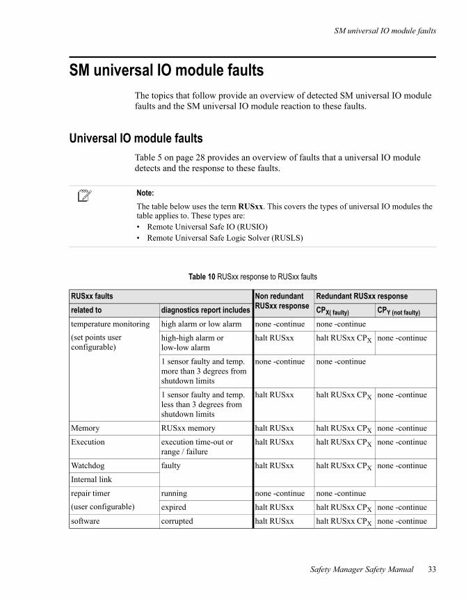
SM universal IO module faultsThe topics that follow provide an overview of detected SM universal IO module faults and the SM universal IO module reaction to these faults.
Universal IO module faultsTable 5 on page 28 provides an overview of faults that a universal IO module detects and the response to these faults.
Note:
The table below uses the term RUSxx. This covers the types of universal IO modules the table applies to. These types are:• Remote Universal Safe IO (RUSIO)• Remote Universal Safe Logic Solver (RUSLS)
Table 10 RUSxx response to RUSxx faults
RUSxx faults Non redundant RUSxx response
Redundant RUSxx response
related to diagnostics report includes CPX( faulty) CPY (not faulty)
temperature monitoring
(set points user configurable)
high alarm or low alarm none -continue none -continue
high-high alarm or low-low alarm
halt RUSxx halt RUSxx CPX none -continue
1 sensor faulty and temp. more than 3 degrees from shutdown limits
none -continue none -continue
1 sensor faulty and temp. less than 3 degrees from shutdown limits
halt RUSxx halt RUSxx CPX none -continue
Memory RUSxx memory halt RUSxx halt RUSxx CPX none -continue
Execution execution time-out or range / failure
halt RUSxx halt RUSxx CPX none -continue
Watchdog faulty halt RUSxx halt RUSxx CPX none -continue
Internal link
repair timer
(user configurable)
running none -continue none -continue
expired halt RUSxx halt RUSxx CPX none -continue
software corrupted halt RUSxx halt RUSxx CPX none -continue

3 – Safety Manager fault detection and reaction
34 Release 151, Issue 1.0
intervention Spurious watchdog interrupt
halt RUSxx halt RUSxx CPX none -continue
assertions
SD input de-energized halt RUSxx
synchronization RUSxx n.a. halt RUSxx CPX none -continue
system software halted RUSxx CP does not start
none -continue
base timer halt RUSxx CPX none -continue
Table 10 RUSxx response to RUSxx faults (continued)
RUSxx faults Non redundant RUSxx response
Redundant RUSxx response
related to diagnostics report includes CPX( faulty) CPY (not faulty)

SM chassis IO faults
Safety Manager Safety Manual 35
SM chassis IO faultsThis section provides information about hardware-related IO faults that are detected in chassis based IO modules. The topics that follow provide an overview of detected chassis IO faults and the Controller reaction to these faults.
Digital input faults (chassis based)Table 11 on page 35 provides an overview of faults that can be detected in relation to chassis based digital inputs and the reaction to these faults.
Table 11 Controller response to chassis IO digital input faults
Digital input faults Non redundant input
Controller response1
1 If the Controller is redundant, both CPs respond the same.
Redundant input, Controller response
Related to Diagnostic message reports
CPX (faulty input) CPY (healthy input)
digital input loop2 (line monitored)
2 This fault is usually caused by an anomaly in the field, not by a defect of an input module.
lead breakage apply FR state to affected inputs
apply FR state
short circuit
loop power2 power output to sensors shorted
apply FR state to affected inputs
use values from CPY
3
3 If values are not available via CPY apply FR state to affected inputs.
none -continue
channel module faulty apply FR state to affected inputs
use values from CPY
3none -continue
module module faulty apply FR state to affected inputs
use values from CPY
3none -continue

3 – Safety Manager fault detection and reaction
36 Release 151, Issue 1.0
Analog input faults (chassis based)Table 12 on page 36 provides an overview of faults that can be detected in relation to chassis based analog inputs and the reaction to these faults.
Table 12 Controller response to chassis IO analog input faults
Analog input faults Non redundant input
Controller response1
1 If the Controller is redundant, both CPs respond the same.
Redundant input, Controller response
Related to Diagnostic message reports
CPX (faulty input) CPY (healthy input)
analog input value below low transmitter alarm level per range
none- continue for 0-20mA, 0-10V
none- continue for 0-20mA, 0-10V
bottom scale for 4-20mA, 2-10V
bottom scale for 4-20mA, 2-10V
above high transmitter alarm level all ranges
none- continue none- continue
loop power (SAI-1620m)
External voltage monitoring fault
none- continue none- continue
channel module faulty apply FR state use values from CPY
2
2 If values are not available via CPY apply FR state to affected inputs.
none- continue
module module faulty apply FR state use values from CPY 2
none- continue
Internal power down
SM chassis IO faults
Safety Manager Safety Manual 37
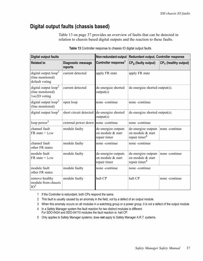
Digital output faults (chassis based)Table 13 on page 37 provides an overview of faults that can be detected in relation to chassis based digital outputs and the reaction to these faults.
Table 13 Controller response to chassis IO digital output faults
Digital output faults Non redundant output
Controller response1
1 If the Controller is redundant, both CPs respond the same.
Redundant output, Controller response
Related to Diagnostic message reports
CPX (faulty output) CPY (healthy output)
digital output loop2 (line monitored) default voting
2 This fault is usually caused by an anomaly in the field, not by a defect of an output module.
current detected apply FR state apply FR state
digital output loop2 (line monitored) 1oo2D voting
current detected de-energize shorted output(s)
de-energize shorted output(s).
digital output loop2 (line monitored)
open loop none -continue none -continue
digital output loop2 short circuit detected de-energize shorted output(s)
de-energize shorted output(s).
loop power3
3 When this anomaly occurs on all modules in a watchdog group or a power group, it is not a defect of the output module.
external power down none -continue none -continue
channel fault FR state = Low
module faulty de-energize outputs on module & start repair timer
de-energize outputs on module & start repair timer4
4 In a Safety Manager system the fault reaction for two distinct modules is different. For SDO-0424 and SDO-04110 modules the fault reaction is: halt CP.
none -continue
channel fault other FR states
module faulty none -continue none -continue
module fault FR state = Low
module faulty de-energize outputs on module & start repair timer
de-energize outputs on module & start repair timer4
none -continue
module fault other FR states
module faulty none -continue none -continue
remove healthy module from chassis IO5
5 Only applies to Safety Manager systems; does not apply to Safety Manager A.R.T. systems.
module faulty halt CP halt CP none -continue
3 – Safety Manager fault detection and reaction
38 Release 151, Issue 1.0
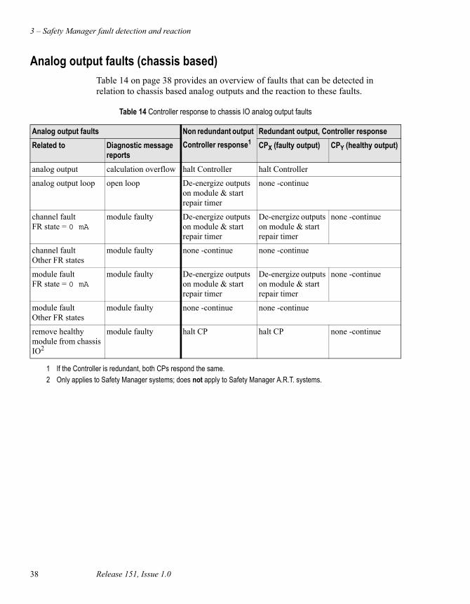
Analog output faults (chassis based)Table 14 on page 38 provides an overview of faults that can be detected in relation to chassis based analog outputs and the reaction to these faults.
Table 14 Controller response to chassis IO analog output faults
Analog output faults Non redundant output
Controller response1
1 If the Controller is redundant, both CPs respond the same.
Redundant output, Controller response
Related to Diagnostic message reports
CPX (faulty output) CPY (healthy output)
analog output calculation overflow halt Controller halt Controller
analog output loop open loop De-energize outputs on module & start repair timer
none -continue
channel fault FR state = 0 mA
module faulty De-energize outputs on module & start repair timer
De-energize outputs on module & start repair timer
none -continue
channel fault Other FR states
module faulty none -continue none -continue
module fault FR state = 0 mA
module faulty De-energize outputs on module & start repair timer
De-energize outputs on module & start repair timer
none -continue
module fault Other FR states
module faulty none -continue none -continue
remove healthy module from chassis IO2
2 Only applies to Safety Manager systems; does not apply to Safety Manager A.R.T. systems.
module faulty halt CP halt CP none -continue

SM universal IO channel faults
Safety Manager Safety Manual 39
SM universal IO channel faultsThis section provides information about hardware-related IO faults that are detected in universal IO modules. The topics that follow provide an overview of detected universal IO faults and the reaction of the Controller (or universal module) to these faults.
Digital input faults (remote)Table 15 on page 39 provides an overview of faults that can be detected in relation to remote digital inputs and the reaction to these faults.
Table 15 Controller response to universal digital input faults
Digital input faults Non redundant input
Controller response1
1 If the Controller is redundant, both CPs respond the same.
Redundant input, Controller response
Related to Diagnostic message reports
CPX (faulty input) CPY (healthy input)
digital input loop2 (line monitored)
2 This fault is usually caused by an anomaly in the field, not by a defect of an input module.
lead breakage apply FR state to affected inputs
apply FR state
short circuit
channel module faulty apply FR state to affected inputs
use values from CPY
2none -continue
module module faulty apply FR state to affected inputs
use values from CPY
2none -continue
3 – Safety Manager fault detection and reaction
40 Release 151, Issue 1.0
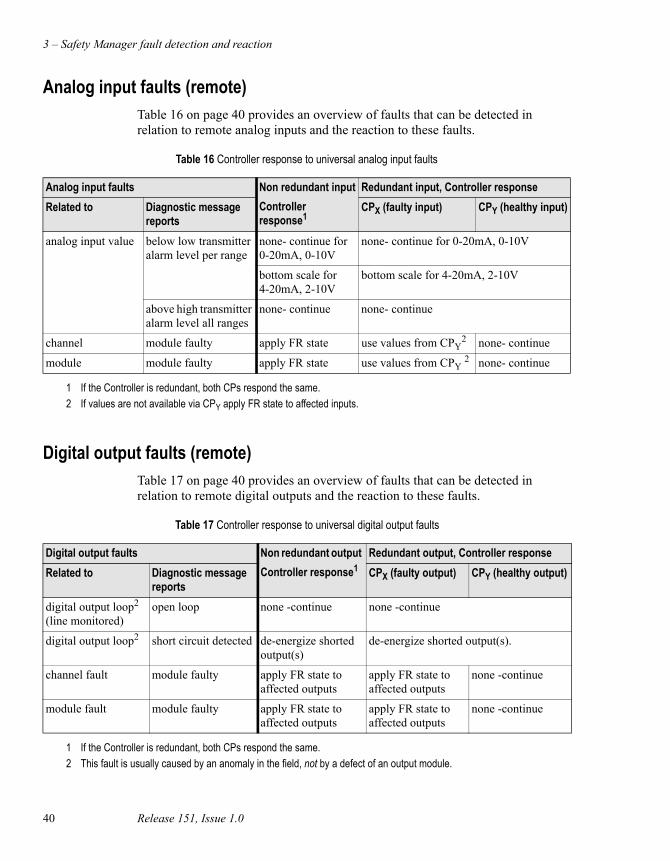
Analog input faults (remote)Table 16 on page 40 provides an overview of faults that can be detected in relation to remote analog inputs and the reaction to these faults.
Digital output faults (remote)Table 17 on page 40 provides an overview of faults that can be detected in relation to remote digital outputs and the reaction to these faults.
Table 16 Controller response to universal analog input faults
Analog input faults Non redundant input
Controller response1
1 If the Controller is redundant, both CPs respond the same.
Redundant input, Controller response
Related to Diagnostic message reports
CPX (faulty input) CPY (healthy input)
analog input value below low transmitter alarm level per range
none- continue for 0-20mA, 0-10V
none- continue for 0-20mA, 0-10V
bottom scale for 4-20mA, 2-10V
bottom scale for 4-20mA, 2-10V
above high transmitter alarm level all ranges
none- continue none- continue
channel module faulty apply FR state use values from CPY2
2 If values are not available via CPY apply FR state to affected inputs.
none- continue
module module faulty apply FR state use values from CPY 2 none- continue
Table 17 Controller response to universal digital output faults
Digital output faults Non redundant output
Controller response1
1 If the Controller is redundant, both CPs respond the same.
Redundant output, Controller response
Related to Diagnostic message reports
CPX (faulty output) CPY (healthy output)
digital output loop2 (line monitored)
2 This fault is usually caused by an anomaly in the field, not by a defect of an output module.
open loop none -continue none -continue
digital output loop2 short circuit detected de-energize shorted output(s)
de-energize shorted output(s).
channel fault module faulty apply FR state to affected outputs
apply FR state to affected outputs
none -continue
module fault module faulty apply FR state to affected outputs
apply FR state to affected outputs
none -continue

SM universal IO channel faults
Safety Manager Safety Manual 41
Analog output faults (remote)Table 18 on page 41 provides an overview of faults that can be detected in relation to remote analog outputs and the reaction to these faults.
Compare error handlingThis section provides information about compare errors and how they are handled by the system. Compare errors are software-related faults. The topics that follow describe how the system deals with:
• IO compare errors and system response, and
• Compare error detection and synchronization
Note:
The table below uses the term RUSxx. This covers the types of universal IO modules the table applies to. These types are:• Remote Universal Safe IO (RUSIO)• Remote Universal Safe Logic Solver (RUSLS)
Table 18 Controller response to universal analog output faults
Analog output faults Non redundant output
Controller response1
1 If the Controller is redundant, both CPs respond the same.
Redundant output, Controller response
Related to Diagnostic message reports
CPX (faulty output) CPY (healthy output)
analog output calculation overflow halt RUSxx halt RUSxx
analog output loop open loop none -continue none -continue
channel fault module faulty Apply FR state to affected outputs
Apply FR state to affected outputs
none -continue
module fault module faulty Apply FR state to affected outputs
Apply FR state to affected outputs
none -continue

3 – Safety Manager fault detection and reaction
42 Release 151, Issue 1.0
IO compare errors and system response
For proper operation both Control Processors of a redundant system must have identical IO values at the beginning and at the end of each application cycle.
An IO compare error is generated as soon as the Controller detects a difference between the IO values of CP1 and CP2, or RUSxx1 and RUSxx2.
The Controller responds towards IO compare errors by applying the fault reaction state to the faulty IO.
Table 19 on page 42 shows the relation between Input and output compare faults, alarm markers and Controller reaction.
Note
Because of the high level of self-testing and fault-handling by Safety Manager, the actual occurrence of a compare error is very unlikely.
Note:
The table below uses the term RUSxx. This covers the types of universal IO modules the table applies to. These types are:• Remote Universal Safe IO (RUSIO)• Remote Universal Safe Logic Solver (RUSLS)
Table 19 Controller reaction to IO compare errors
IO compare error Controller reaction
Related to Occurs when detecting a Non redundant IO Redundant IO
digital inputs (chassis) difference in the input values persists for more than 3 application cycles
apply FR state to affected inputs
apply FR state
digital inputs (universal) 3oo4 voting, 2oo3 voting, apply FR state
analog inputs (chassis) deviation of >2% in the input values persists for more than 3 application cycles
apply FR state apply FR state
analog inputs (universal) 3oo4 voting, 2oo3 voting, apply FR state
digital outputs (chassis) difference in the output values of a redundant SM Controller or RUSxx
apply FR state apply FR state
digital outputs (universal)
analog outputs (chassis) difference in the output values of a redundant SM Controller or RUSxx
apply FR state apply FR state
analog outputs (universal)

SM universal IO channel faults
Safety Manager Safety Manual 43
Compare error detection and synchronization
Input compare errors
Input compare error detection applies to all hardware inputs.
Differences in the input status read should be momentary. Persisting differences could be the result of detected hardware faults. In that case, the faulty input channel is reported in the diagnostics, and both Control Processors use the process value read from the healthy input channel.
A persisting difference in status of an input while no faults are detected at the accessory hardware channels leads to an input compare error. The resulting input is the result of voting (in case of universal IO) or by applying the FR state (if majority voting is not possible).
Output compare errors
An output compare error applies to all hardware outputs.
In configurations with a redundant Controller, both Control Processors will continuously have an identical application status, resulting in identical process outputs.
An output compare error is detected if there is a difference between the Control Processors or two paired universal IO modules with respect to:
• the calculated application output values for hardware outputs (AO/DO) or communication outputs (DO, BO) to another Safety Manager.
• the actual application values sent to hardware outputs (AO/DO) or communication outputs (DO, BO) to another Safety Manager.
If outputs are no longer synchronized an Output Compare error is generated.
Input synchronization algorithm
In configurations with a redundant Controller, the process inputs are scanned every application program cycle by both Control Processors.
Each Control Processor executes the application cycle independently of the other. It is therefore essential that they use identical values for the process inputs.
There is no problem if the process inputs are stable. However, if an input value changes when the Control Processors read the value, both Control Processors could read a different value. In such cases, an identical input value in the Controller is obtained via input synchronization.
If inputs are no longer synchronized, the signal value freezes to the last known synchronized state and a synchronization timer -equal to three application cycles- is started.

3 – Safety Manager fault detection and reaction
44 Release 151, Issue 1.0
This state is maintained until:
• a synchronized state is obtained or
• the synchronization timer runs out
If a synchronized state is not achieved within three application cycles the fault reaction is activated and an Input Compare error is generated.
If a synchronized state is achieved within two application cycles:
• the synchronization timer is reset and
• the synchronized scanner value is used
Synchronization algorithms are used for digital and analog inputs.
Digital input synchronization
A digital input compare error is detected if the inputs of both Control Processors or two paired universal IO modules are stable but different (for example Control Processor 1 continuously ‘0’, Control Processor 2 continuously ‘1’), for the duration of three application cycles.
The input compare error detection algorithm puts the following demands on the dynamic nature of the digital process inputs:
1. If an input state changes, it must become stable again within two application cycles.
2. The frequency of continuously changing inputs must be less than two application cycles.
Analog input synchronization
For analog inputs, the synchronized value is the mean value of the input values. An input compare error is detected if the input values differ more than 2% of the full scale for the duration of three application cycles.
The input compare error detection algorithm puts the following demands on the dynamic nature of the analog process inputs:
1. For inputs allocated on a redundant module (type SAI-0410 or SAI-1620m), the slope steepness must be less than 125 mA/s.
2. For inputs allocated on a non-redundant module (type SAI-1620m), the slope steepness must be less than 20 mA/s.
3. For inputs allocated to a SM universal IO module the slope steepness must be less than 700 mA/s.

SM universal IO channel faults
Safety Manager Safety Manual 45
.
Caution
Analog input compare errors may, for example, occur when calibrating smart transmitters using hand-held terminals. Refer to the Troubleshooting and Maintenance Guide for details on calibrating smart transmitters that are connected to Safety Manager analog inputs.
3 – Safety Manager fault detection and reaction
46 Release 151, Issue 1.0
Calculation errors
Calculation errors may occur in the application program.
Calculation errors occur if:
• The calculated value of an analog output is outside the specified range.
• The square root of a negative number is taken.
• A logarithm function is loaded with a negative value or zero
• A divide-by-zero occurs.
• An overflow occurs during a calculation.
• The value for a counter or (variable) timer is outside the specified range.
Calculation errors reflect an incorrect design of the application program for the intended function. Once a calculation error occurs for a specific process point, a correct result of successive calculations based on this point cannot be guaranteed.
Preventing calculation errors
Calculation errors can be prevented as follows:
• Overall process design.
• Inclusion of Safety Manager diagnostic data.
• Validation of signals in the Functional Logic Diagrams (FLDs).
• Exception handling during the actual calculation.
Prevention by design
In line with good engineering practice for safety applications - as promoted by IEC 61508 - calculation errors should be avoided by design. This means that an application should be designed in such a way that the operands of a symbol in the FLDs can never get an invalid value. The design approach starts with making sure that input values as obtained from the process remain within a predefined range. This approach ensures that the derived values are also valid for successive operations.
Caution
In case a calculation error occurs, Safety Manager will go to its halt state.

Safety Manager Safety Manual 47
4Safety Manager special functions
On-line modification
Introduction
On-line modification (OLM) is a Safety Manager option which allows you to modify the application software, embedded system software and the Safety Manager hardware configuration of systems with a redundant Controller while the system remains operational.
During the on-line modification, the changes are implemented in the Control Processors one by one. While one Control Processor is being modified, the other Control Processor continues safeguarding the process.
The engineer executing the OLM is guided through the OLM procedure step by step by Controller Management which is integrated in the Safety Builder.
Compatibility check
During the modification, Safety Manager performs a compatibility check of the application-related data, to guarantee a safe changeover from the existing configuration to the new configuration. The system reports all application changes in a detailed report in the Extended Diagnostics.
The user is expected to verify each reported change before starting up the system.
When modifications are implemented in an application, only a functional logic test of the modified functions is required by, for example, TÜV. This must be done when the final verification of the implemented changes is obtained via the built-in sheet difference report in Controller Management diagnostics.
Tip:
Detailed information about On-line modification can be found in On-line Modification Guide

4 – Safety Manager special functions
48 Release 151, Issue 1.0
Safety Manager networks
If a system has been integrated into a Safety Manager communication network (SafeNet), it performs a compatibility check for all connected systems.
If it detects inconsistencies or if the check of a specific system cannot be completed for some reason, an error message is generated in the extended diagnostics. In case such an error occurs, no data will be exchanged with that system. The communication can only be established after a successful completion of the compatibility check by any of the Safety Managers that can communicate with each other, initiated via a QPP reset.

SafeNet communication
Safety Manager Safety Manual 49
SafeNet communication Safety Managers can be connected together to form safety-related networks. The protocol used for this network is called SafeNet.
SafeNet is available to Safety Managers for:
• Distributed processing
• Sharing safe data for joint SIS related tasks
• SIL3, TUV approved, communication
• Remote load
NetworksData that is transferred between Safety Managers is represented in function logic diagrams as IO symbols with the location FSC. Points with location FSC can be of type DI or DO (markers), BI or BO (registers), and may be configured for safe and non-safe functions.
Protocol versus response timeThe response time between Node ID and logical Peer ID depends on:
• the application program cycle time of the Node ID and Peer ID system in the logical link.
• the delay caused by the data layer protocol of the physical links.
Response time and time-out time are related.
The minimum time-out depends on the system application cycle and the type of communication link.
The time-out time that is used must be larger than the maximum response time.
The response time to a communication request highly depends on the actual states of both Node ID and Peer ID system at the time of the request.
The maximum response time equals the sum of:
• the application cycle time of the Node ID plus
• the application cycle time of the Peer ID plus
• the expected communication delay.
The Node ID periodically sends data to the Peer ID systems and initiates a request for data from the Peer IDs. A correct answer must be provided for within the time-out period; when not received in time, the link is regarded faulty.

4 – Safety Manager special functions
50 Release 151, Issue 1.0
A new data transmission and request for a Peer ID are initiated after the Peer ID reply to the previous request has been received. This could be equal to the time-out time, but usually it is shorter.
SafeNet time-out time
All systems within the network monitor the operation of a communication link by means of a time-out.
• The time-out can be set for each individual logical link and must be chosen such that it stays within the Process Safety Time (PST) for the Safety Instrumented Functions (SIFs) involved.
• The time-out time set must be at least 2x the calculated response time.
Ethernet communication
When communicating via Ethernet you should be aware of the following:
• “Ethernet communication risks” on page 50
• “Ethernet bandwidth and response time calculation” on page 51
Ethernet communication risks
When devices communicate via an Ethernet based local area network (LAN), their information is contained and sent in packets. This is no different when using SafeNet through Ethernet. However, Ethernet has far less timing restrictions and, when sending SafeNet packets together with other application packets, some packets may suffer critical delay or get lost if a network gets congested.
Packet losses and network congestion may occur if e.g.:
• several devices start transmitting packets at the same time and/or,
• a single device generates a peak in network traffic,
When the Ethernet is dedicated to a single Safenet, issues do not take place:
• No single SafeNet configuration can cause a 100MB Ethernet to operate at its maximum capacity (Safety Builder checks this in the configuration stage).
Attention:1. Risks are involved when using SafeNet on an insecure, open or shared Ethernet,
where downtime, delays, loss and/or access to packets can be caused by other devices on the LAN. Such risks can be caused by office computers, network printers, servers and open access points (such as wifi access points, WAN routers, etc.)
2. Viruses and applications such as Instant Messanging Application may affect SafeNet reliability when active on the same Ethernet.

SafeNet communication
Safety Manager Safety Manual 51
Packets are vulnerable to modifications or alterations when accessed by external systems: Applications running on these systems could (deliberately or via a virus infection) intercept, delay and/or alter packets.
Ethernet bandwidth and response time calculation
Please consult the Software Change Notifications issued with your Safety Builder software for ways to determine bandwidth and response time.
Conventional serial communication
Please consult the Software Change Notifications issued with your Safety Builder software for ways to determine bandwidth and response time.
ResetThe reset function is a means to allow Safety Manager to recover from an abnormal state. (Running fault free is the normal operating state.)
Safety related resets allow the recovery from all fault types whereas non safety related resets allow the recovery of non safety related faults only.
Safety related resets can be given via the reset key switch, via the Remote Reset button in Safety Builder (after enabling in the configuration).

4 – Safety Manager special functions
52 Release 151, Issue 1.0
System response towards a safety related resetThe response to a safety related reset action depends on the QPP state of the Control Processor. The QPP states that make the Control Processor respond to a reset are listed below:
QPP state Control Processor(s) details Effect(s) of a reset
Running The Control Processor is running without faults.
No effect on the SM Controller state.
Running with Flt The Control Processor is running with faults.
1. The faults logged in the actual fault database are moved to the historical fault database.
2. The actual faults database is cleared.
3. The reset is logged.
CPReady (after startup or after recovering from a fault)
Both Control Processors contain the same application.
The application will be started in the ready QPP.
CPReady (during an OLM procedure)
Both Control Processors contain different applications.
An application is switch-over is started from the running Control Processor to the ready (idle) Control Processor.
Halt with Flt (during an OLM procedure)
Both Control Processors contain different applications.
The Control Processor was halted due to a fault that was detected during the OLM compatibility check.
1. The (actual?) faults database is cleared.
2. A new diagnostic cycle is run.
3. The results are logged in the (actual?) fault database.
After the diagnostic cycle is finished, the QPP:
• remains in the Halt with Flt state if faults are detected during the diagnostic cycle;
• goes to the CPReady (during OLM) state if no faults are detected.

SafeNet communication
Safety Manager Safety Manual 53
Simulation modeSimulation mode of Safety Manager is a TÜV approved function that enables the user to test (i.e. verify and validate) the application and configuration in a simulated environment.
Simulation mode has the following features:
• Simulation mode only requires Control Processor hardware (such as a Training and Simulation Unit) that matches the actual Control Processor configuration,
• verification and validation work as in Operation mode,
• external communication can be used as in Operation mode; communication behavior is real-time and identical to actual operation.
Using Simulation mode offers a number of advantages:
• the user has the possibility to create and test many more “what if” scenarios than in Operation mode,
• a high level of probability is achieved in the sense that the (modified) application and/or configuration is correct and functions as defined,
• testing can be done for any given modification - irrespective of its size - up to the complete system.
Note
The application cycle time in Simulation mode matches that in Operation mode. The deviation is < 10%.

4 – Safety Manager special functions
54 Release 151, Issue 1.0

Safety Manager Safety Manual 55
5General guidelines for TÜV-approved applications
GeneralSafety Manager can be used for processes which require, amongst others, TÜV approval. The requirements for the safety applications are the following:
1. The maximum application cycle time is half the Process Safety Time. For example, the accepted Process Safety Time for a burner control system in accordance with TRD-411 for boilers > 30 kW (July 1985) Table 1, TRD-412 (July 1985) Table 1 and DIN 4788 (June 1977) Part 2 Chapter 3.2.3.2 1 is 1 second.
This implies that the application cycle time must be 0.5 second or less. The application cycle time is monitored by the SM Controller and can be seen on the System Information screen of Controller Management.
The application cycle time is limited to 2.3 seconds by the watchdog, resulting in a maximum typical cycle time of 2 seconds. The typical application cycle time can be calculated by the Safety Manager MTBF and Cycle time calculation tool. This tool is available via Honeywell SMS and includes:
- cycle time estimation based upon amount of IO, DTI, application complexity and communication parameters,
- MTBF calculation
2. If Safety Manager detects a fault in output hardware that is configured with Fault Reaction Low or 0mA, it will de-energize the faulty output channels, faulty output modules or instead de-energize all outputs. The de-energization of faulty output channels, faulty output modules or all outputs is fully implemented in the software and cannot be influenced by the user (see also item 3).
If an output module (configured with Fault Reaction Low or 0mA) is detected faulty, the outputs of that output module are switched off and the repair timer is started (if configured). The Control Processor then verifies the switch-off.
- If the switch-off is verified the faulty output module can be replaced without affecting the status of the Control Processor and the
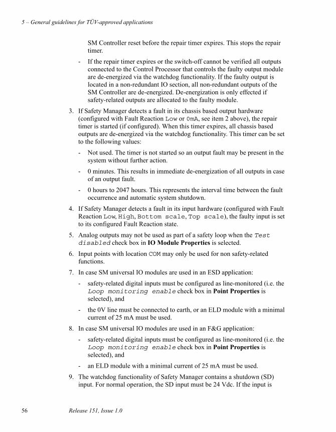
5 – General guidelines for TÜV-approved applications
56 Release 151, Issue 1.0
SM Controller reset before the repair timer expires. This stops the repair timer.
- If the repair timer expires or the switch-off cannot be verified all outputs connected to the Control Processor that controls the faulty output module are de-energized via the watchdog functionality. If the faulty output is located in a non-redundant IO section, all non-redundant outputs of the SM Controller are de-energized. De-energization is only effected if safety-related outputs are allocated to the faulty module.
3. If Safety Manager detects a fault in its chassis based output hardware (configured with Fault Reaction Low or 0mA, see item 2 above), the repair timer is started (if configured). When this timer expires, all chassis based outputs are de-energized via the watchdog functionality. This timer can be set to the following values:
- Not used. The timer is not started so an output fault may be present in the system without further action.
- 0 minutes. This results in immediate de-energization of all outputs in case of an output fault.
- 0 hours to 2047 hours. This represents the interval time between the fault occurrence and automatic system shutdown.
4. If Safety Manager detects a fault in its input hardware (configured with Fault Reaction Low, High, Bottom scale, Top scale), the faulty input is set to its configured Fault Reaction state.
5. Analog outputs may not be used as part of a safety loop when the Test disabled check box in IO Module Properties is selected.
6. Input points with location COM may only be used for non safety-related functions.
7. In case SM universal IO modules are used in an ESD application:
- safety-related digital inputs must be configured as line-monitored (i.e. the Loop monitoring enable check box in Point Properties is selected), and
- the 0V line must be connected to earth, or an ELD module with a minimal current of 25 mA must be used.
8. In case SM universal IO modules are used in an F&G application:
- safety-related digital inputs must be configured as line-monitored (i.e. the Loop monitoring enable check box in Point Properties is selected), and
- an ELD module with a minimal current of 25 mA must be used.
9. The watchdog functionality of Safety Manager contains a shutdown (SD) input. For normal operation, the SD input must be 24 Vdc. If the input is

Safety Manager Safety Manual 57
forced to 0 V, a Safety Manager shutdown and de-energization of the outputs take place, independent of the QPP.
10. The watchdog functionality of SM universal IO modules contains a shutdown (SD) input. For normal operation, the SD input must be connected to a SD switch including a termination resistor of 500 ohm. If the SD loop is opened, a SM universal IO module shuts down and de-energization of its outputs take place.
11. For more details on IO wiring details, termination of IO signals and power supply distribution see Hardware Reference.
12. The Diagnostic Test Interval (DTI, the time in which all IO tests are executed) can be set for each SM Controller in the Controller Properties in the Network Configurator.
13. The repair timer can be set for each SM Controller in the Controller Properties in the Hardware Configurator.
14. The values of the voltage monitor analog input channels of the SAI-1620m modules must be checked in the application to ensure that they are within the transmitter power supply range of the transmitters connected to that analog input module.
15. To reduce the influence of disturbances on the power supply lines, all major metal parts (cabinet sidewalls, doors, 19-inch chassis, horizontal bus chassis and flaps, swing frames, etc.) must be properly grounded.
16. In case an external 24 Vdc is used, a power supply filter directly fitted after the power supply input terminals is required.
17. Grounding of the power supplies of Safety Manager is only permitted for the 0 Vdc. Grounding of the +24 Vdc / +48 Vdc / +60 Vdc / +110 Vdc is not allowed because an earth fault results in an unsafe situation.
18. In case the floating ground principle is not preferred, the design of the SM universal IO module supports the grounding of the 0VDC level. Digital inputs must be configured as line monitored to ensure the integrity of the input signal. Dedicated resistor networks are documented in the Hardware Reference.
19. The wiring of the external power supply (24 Vdc) and the internal power supply (5 Vdc) must be physically separated. This can be realized by using separate ducts and a separate power supply distribution.
20. Do not use radio frequency transmitting equipment within a radius of 1 m (3 ft) of the system cabinet when the doors are opened.
21. Safety-related inputs require the use of tested input modules (SDI-1624, SDI-1648, SAI-1620mm, SAI-0410, SDIL-1608, or SM universal IO module) and safety-related input sensors (transmitters). If the input sensors (transmitters) are not safety related, multiple sensors (transmitters) must be used.
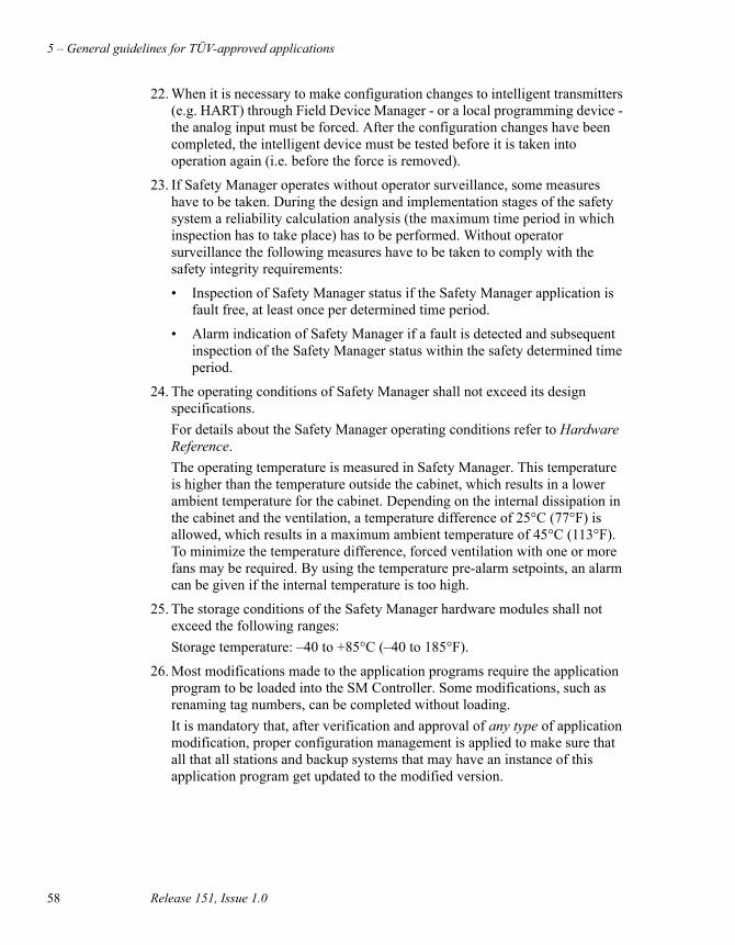
5 – General guidelines for TÜV-approved applications
58 Release 151, Issue 1.0
22. When it is necessary to make configuration changes to intelligent transmitters (e.g. HART) through Field Device Manager - or a local programming device - the analog input must be forced. After the configuration changes have been completed, the intelligent device must be tested before it is taken into operation again (i.e. before the force is removed).
23. If Safety Manager operates without operator surveillance, some measures have to be taken. During the design and implementation stages of the safety system a reliability calculation analysis (the maximum time period in which inspection has to take place) has to be performed. Without operator surveillance the following measures have to be taken to comply with the safety integrity requirements:
• Inspection of Safety Manager status if the Safety Manager application is fault free, at least once per determined time period.
• Alarm indication of Safety Manager if a fault is detected and subsequent inspection of the Safety Manager status within the safety determined time period.
24. The operating conditions of Safety Manager shall not exceed its design specifications.
For details about the Safety Manager operating conditions refer to Hardware Reference.
The operating temperature is measured in Safety Manager. This temperature is higher than the temperature outside the cabinet, which results in a lower ambient temperature for the cabinet. Depending on the internal dissipation in the cabinet and the ventilation, a temperature difference of 25°C (77°F) is allowed, which results in a maximum ambient temperature of 45°C (113°F). To minimize the temperature difference, forced ventilation with one or more fans may be required. By using the temperature pre-alarm setpoints, an alarm can be given if the internal temperature is too high.
25. The storage conditions of the Safety Manager hardware modules shall not exceed the following ranges:
Storage temperature: –40 to +85°C (–40 to 185°F).
26. Most modifications made to the application programs require the application program to be loaded into the SM Controller. Some modifications, such as renaming tag numbers, can be completed without loading.
It is mandatory that, after verification and approval of any type of application modification, proper configuration management is applied to make sure that all that all stations and backup systems that may have an instance of this application program get updated to the modified version.

F&G applications
Safety Manager Safety Manual 59
F&G applicationsFire and Gas (F&G) applications have the following additional requirements:
1. Each visual indication (alarm, override or test, failure) shall have its own dedicated digital output. This digital output may be a hardware output or a communication output, e.g. to a DCS system. Override and test status may be combined in one visual indication. Alphanumeric displays are not supported.
2. Redundant power supplies must be connected to Safety Manager in such a way that the redundant power supplies do not fail at the same time, e.g. by using different primary power sources (e.g. 220 Vac mains and a 24 Vdc from a battery backup). Detection of power supply failure (e.g. via a voltage-monitoring module) shall be part of the system design.
3. Faults in the Fire & Gas detection system are indicated visually. This indication must also be active if the Fire & Gas detection system has been switched off. This can be set up as shown in Figure 8 on page 59, using a normally de-energized relay, or via a visual indication in a DCS display which is activated if the communication to the Fire & Gas detection system fails. The protected side of the fuses are connected to a voltage-monitoring device to detect blown fuses.
Figure 8 Power supply
Power Supply Unit 2e.g. 24 VDC
Power Supply Unit 1e.g. 200 VAC
200 VAC / 24 VDC
Voltage Monitoring
Safety Manager
Controllerfault
0 VDC
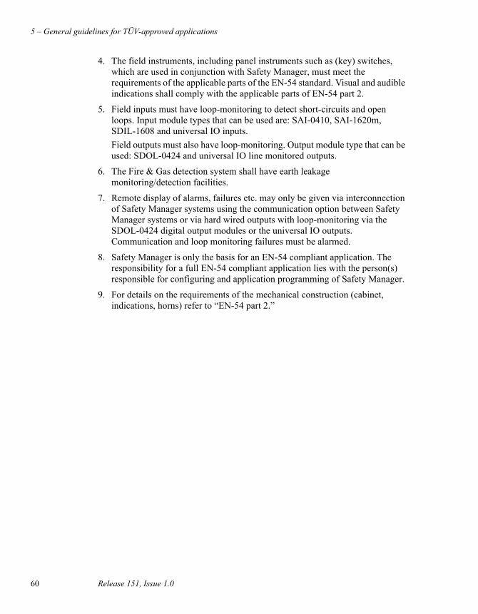
5 – General guidelines for TÜV-approved applications
60 Release 151, Issue 1.0
4. The field instruments, including panel instruments such as (key) switches, which are used in conjunction with Safety Manager, must meet the requirements of the applicable parts of the EN-54 standard. Visual and audible indications shall comply with the applicable parts of EN-54 part 2.
5. Field inputs must have loop-monitoring to detect short-circuits and open loops. Input module types that can be used are: SAI-0410, SAI-1620m, SDIL-1608 and universal IO inputs.
Field outputs must also have loop-monitoring. Output module type that can be used: SDOL-0424 and universal IO line monitored outputs.
6. The Fire & Gas detection system shall have earth leakage monitoring/detection facilities.
7. Remote display of alarms, failures etc. may only be given via interconnection of Safety Manager systems using the communication option between Safety Manager systems or via hard wired outputs with loop-monitoring via the SDOL-0424 digital output modules or the universal IO outputs. Communication and loop monitoring failures must be alarmed.
8. Safety Manager is only the basis for an EN-54 compliant application. The responsibility for a full EN-54 compliant application lies with the person(s) responsible for configuring and application programming of Safety Manager.
9. For details on the requirements of the mechanical construction (cabinet, indications, horns) refer to “EN-54 part 2.”

List of abbreviations
Safety Manager Safety Manual 61
List of abbreviationsAI Analog Input
AO Analog Output
ASM Abnormal Situation Management
ATEX Explosive Atmosphere (in French: “ATmospheres EXplosibles”)
A.R.T. Advanced Redundancy Technique
BKM Battery and Key switch Module
BMS Burner Management System
CDA Common Data Access
CEE Control Execution Environment
CP Control Processor
DCF Digital Coded Frequency
DCS Distributed Control System
DI Digital Input
DO Digital Output
DTI Diagnostic Test Interval
E/E/PES Electrical/Electronic/Programmable Electronic System
EMC Electromagnetic Compatibility
ESD • ElectroStatic Discharge
• Emergency ShutDown system
EUC Equipment Under Control
EUT Equipment Under Test
F&G Fire and Gas
FB Function Block
FDM Field Device Management
FGS Fire and Gas System
FLD Functional Logic Diagram
FSC Fail Safe Communication
FTA Field Termination Assembly
FTE Fault Tolerant Ethernet
GPS Global Positioning System
HIPS High-Integrity Protection Systems
HMI Human Machine Interface
HSE High Speed Ethernet
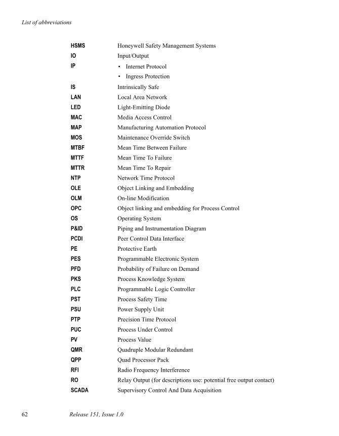
List of abbreviations
62 Release 151, Issue 1.0
HSMS Honeywell Safety Management Systems
IO Input/Output
IP • Internet Protocol
• Ingress Protection
IS Intrinsically Safe
LAN Local Area Network
LED Light-Emitting Diode
MAC Media Access Control
MAP Manufacturing Automation Protocol
MOS Maintenance Override Switch
MTBF Mean Time Between Failure
MTTF Mean Time To Failure
MTTR Mean Time To Repair
NTP Network Time Protocol
OLE Object Linking and Embedding
OLM On-line Modification
OPC Object linking and embedding for Process Control
OS Operating System
P&ID Piping and Instrumentation Diagram
PCDI Peer Control Data Interface
PE Protective Earth
PES Programmable Electronic System
PFD Probability of Failure on Demand
PKS Process Knowledge System
PLC Programmable Logic Controller
PST Process Safety Time
PSU Power Supply Unit
PTP Precision Time Protocol
PUC Process Under Control
PV Process Value
QMR Quadruple Modular Redundant
QPP Quad Processor Pack
RFI Radio Frequency Interference
RO Relay Output (for descriptions use: potential free output contact)
SCADA Supervisory Control And Data Acquisition

List of abbreviations
Safety Manager Safety Manual 63
SCN Software Change Notification (formerly addressed as Release Note)
SIC System Interconnection Cable
SIF Safety Instrumented Function
SIL Safety Integrity Level
SIS Safety Instrumented System
SMOD Secondary Means Of De-energization
SOE Sequence Of Events
SRS Safety-Related System
SSC Serial Communication Channel
STP Shielded Twisted Pair
USI Universal Safety Interface
UTP Unshielded Twisted Pair
UTC Coordinated Universal Time (Universal Time Coordinated)
WAN Wide Area Network

List of abbreviations
64 Release 151, Issue 1.0

Fax Transmittal Fax Number: +31 (0)73 6219 125
Reader Comments
To: Honeywell Safety Management Systems, attn. Technical Documentation Group
From: Name: Date:
Title:
Company:
Address:
City: State: Zip:
Telephone: Fax:
Safety Manager Safety Manual, Release 151, Issue 1.0, 20 February 2013
Comments:
You may also call the Technical Documentation Group at +31 (0)73 6273 273,email Honeywell SMS at [email protected], or write to:
Honeywell Process SolutionsSafety Management SystemsP.O. box 1165201 AC ‘s-HertogenboschThe Netherlands
Safety ManagerUser documentation

Honeywell Process SolutionsSafety Management SystemsRietveldenweg 32a5222 AR ‘s-HertogenboschThe Netherlands