safety recall campaign technical service bulletin...safety recall campaign technical service...
TRANSCRIPT

NUMBER DATESC 075 June 2009
Circulate To: X General Manager X Service Manager X Parts Manager
X Service Advisor(s) X Technician(s) X Body Shop Manager X Fleet Repair
File Under: Campaign
SUBJECT: Kia Motors Logo 4/C - Medium
gRoUp MoDElCampaign 2001-2004MY Optima (MS)
safety recall campaign technical service Bulletin
repair/replacement of suBframeThis bulletin provides information related to a service campaign for the inspection and related repair, or replacement, if necessary, of the subframe due to corrosion in 2001-2004 Kia optima vehicles produced from 10/6/2000 ~ 11/19/2003, that are currently registered in the states where heavy amounts of road salt is used. This condition is typically related to a lack of regular cleaning of the vehicle underbody as outlined in the “Underbody Maintenance” section of the vehicle’s owner’s manual. In rare cases, the corrosion may be sufficient to warrant a replacement of the subframe.owners of 2001-2004 Kia optima vehicles currently registered in the 21 states which are known to use heavy amounts of road salt are being notified to schedule an appointment with the nearest Kia dealer. The 21 states are: CT, DC, DE, IA, Il, IN, MA, MD, ME, MI, MN, Mo, NH, NJ, NY, oH, pA, RI, VT, WI, WV. This TSB sets out the procedures to be followed in conducting the inspection and repair, or replacement if necessary, of the vehicle’s subframe. The dealer is also to provide instruction to the customer on the proper maintenance of the underbody of the vehicle when exposed to road salt conditions, consistent with the information contained in the "Underbody Maintenance" section in the vehicle’s owner’s manual.
Vehicle In
YES
YES
NO
NO
Lift-down Vehicle Out
Lift-up
Externalperforation or
corrosion?
Possibleto insert?
Subframe replacement(refer to TSB GEN 026)
Visual inspectionof entire subframe
for corrosion
1. Inner: Waxing2. Outer: Undercoating
Drilling: 40mm (2ea)→ LH RR: 1ea, RH, RR: 1ea
Frame thicknessmeasurement
(with jig gauge)
1. Drilling: 40mm - RH (2ea), LH (2ea) 8mm - RH (2ea), LH (2ea)2. Outer: Hammering to loosen corrosion3. Inner: Air blowing4. Removing sludge w/magnetic tool5. Repeat steps 2-4
Excessivecorrosion
1.5mmor less
Above1.5mm
1.5mm
SUMMARY OF SERVICE PROCEDURE
There is no charge to the vehicle owner for this repair. Under applicable law, you may not sell or otherwise deliver any affected 2001-2004MY Optima (MS) until it has been repaired pursuant to the procedures set forth in this bulletin.
NOTICE*

TSB: Safety Recall Campaign 075 optima June 2009
page 2 of 12SUBJECT:
repair/replacement of suBframe
2. Inspect the entire subframe assembly for any external signs of severe corrosion/perforation.
a) If any perforation or open cavity is found in the subframe, do not continue repairing. Replace the subframe according to TSB gEN 026. If no signs of perforation or severe corrosion are found, continue to step (b).
b) Using a hammer, lightly tap the entire subframe in several areas to check for any material which may be nearing the perforation stage. If the hammer opens up a cavity in the subframe, replace the subframe according to TSB gEN 026.
Raise the vehicle on a hoist in preparation 1. for the underbody inspection of the subframe.
CAMPAIGNSC075
DO NOT REMOVE
Make sure to inspect for any corrosion cavity throughout the subframe, including the sides.
NOTICE*
Inspection Procedure:
open hood and check for SC 075 Campaign completion label on the panel above the master cylinder. If label exists, No FURTHER ACTIoN IS REQUIRED.
If label does not exist, continue to step one (1) of the service procedure until completion.

TSB: Safety Recall Campaign 075 optima June 2009
page 3 of 12SUBJECT:
repair/replacement of suBframe
2. located on the left-rear of the subframe is drilling site location (one) 1. Using a straight edge ruler, scribe or draw a seventy (70) mm line from the end of the horizontal weld (dashed line).
Service Procedure:
1. In preparation for the drilling of the 40 mm hole-saw cuts for the front / rear subframe sites, the following identification procedure must be utilized to ensure the proper drilling location. The 40 mm hole-saw site locations will be numbered as follows: (1-4) / (large Blue Holes).
Front of vehicle(viewed from bottom)
Horizontal Weld
2#
3# 4#
1#
Front of vehicle(viewed from bottom)
Right Left
3. Referencing the dashed line, measure thirty (30) mm from the outer horizontal weld (dashed line) and mark this location. From this new reference mark, measure ten (10) mm forward from this position and mark this location as the center point of the drilling. Drill this location using the forty (40) mm hole-saw (Drill speed recommendation: 380 ~ 470 rpm).
Front of vehicle(viewed from bottom)
30mm
10mm
Use safety glasses, respirator and gloves when performing any procedure using a drill.
CAUTION

TSB: Safety Recall Campaign 075 optima June 2009
page 4 of 12SUBJECT:
repair/replacement of suBframe
4. Repeat this same procedure (Step 4 & 5) for location Two (2) drill site on the right-rear side of the subframe. Drill this location using the 40 mm hole-saw (Drill speed recommendation: 380 ~ 470 rpm).
5. Debur the holes on both sides in several areas around the edges of the 40 mm hole so that an accurate judgment of the subframe material thickness can be made.
Use safety glasses, respirator and gloves when performing any procedure using a drill.
CAUTION
Failure to perform this deburring step may cause a false “pass” on the subframe condition in the following step.
If the metal burrs are left around the hole, they may block the thickness gauge and indicate that the subframe is thicker than it actually is.
WARNING

TSB: Safety Recall Campaign 075 optima June 2009
page 5 of 12SUBJECT:
repair/replacement of suBframe
6. Referencing the 1.5 mm side (smallest width) of the thickness gauge, attempt to slide the thickness gauge over the edge of the hole in several different locations on both left/right rear inspection sites.
a) If the thickness gauge (B) is able to pass over the subframe material, it has failed the 1.5 mm minimum thickness test. Replace the subframe according to TSB gEN 026.
b) If the gauge will not pass over the subframe material, the corrosion preventive treatment can be performed. proceed to the next step.
Ensure that the 1.5mm gauge (smallest width) is used for this test of subframe thickness. Failure to use the correct (1.5mm) gauge will result in unnecessary replacement of subframe.
7a. In preparation for drilling the 40 mm hole-saw site three (3) in the right front, the following method must be used to insure proper drilling location. locate the center point of the right side subframe bushing bolt, use a straight edge to draw a horizontal line for 19 mm inboard. From the end of the 19 mm horizontal line, use a straight edge to draw a vertical line for 294 mm. From the end of the 294 mm vertical line, mark this location as the center point for drilling. Drill this location using the 40 mm hole-saw. (Drill Speed Recommendation: 380 ~ 470 rpm).
Use safety glasses, respirator and gloves when performing any procedure using a drill.
CAUTION
NOTICE*

TSB: Safety Recall Campaign 075 optima June 2009
page 6 of 12SUBJECT:
repair/replacement of suBframe
8. place the lH and RH templates against the underside of the subframe, just parallel to the control arm with the arrows pointing forward. Align the outlines on the templates to the outboard shape of the subframe. Ensure proper orientation of the front (Frt) alignment of the templates for left/right. Use a grease pen to mark through the two holes on each template.
These holes will prevent any water which enters the subframe from becoming trapped.
NOTICE*
No thickness measurements are required in the forward 40 mm drill sites #3 & #4.NOTICE*
7b.In preparation for drilling the 40 mm hole-saw site four (4) in the left front, the following method must be used to insure proper drilling location. locate the center point of the left side subframe bushing bolt, use a straight edge to draw a horizontal line for 21 mm inboard. From the end of the 21 mm horizontal line, use a straight edge to draw a vertical line for 266 mm. From the end of the 266 mm vertical line, mark this location as the center point for drilling. Drill this location using the 40 mm hole-saw. (Drill Speed Recommendation: 380 ~ 470 rpm).

TSB: Safety Recall Campaign 075 optima June 2009
page 7 of 12SUBJECT:
repair/replacement of suBframe
9. Using an 8mm drill, drill four (4) holes in the locations marked in the previous step. Debur all 8mm holes.
Use safety glasses, respirator and gloves when performing any procedure using a drill.
CAUTION
b) Insert the magnetic pick up tool through each of the four 40mm holes and pull the magnet along in either direction as far as possible to remove any larger fragments.
c) Insert air blow gun into each of the four 40mm & 8mm holes. Use shop air to blow as much of the rust particles as possible from inside the subframe. In some cases, if there is a large amount of loose rust scale present you may have to repeat the above steps another 2 to 3 times.
10. Use the following procedures to remove as much of the rust fragments as possible from inside the subframe.
a) Strike the underside of the subframe lightly with a hammer to cause vibration and dislodge any rust scale.
NOTICE*Do not use excessive force near the edges of the 40 mm holes to prevent deformation in this area.

TSB: Safety Recall Campaign 075 optima June 2009
page 8 of 12SUBJECT:
repair/replacement of suBframe
Use safety glasses and a respirator when performing this procedure to protect against any flying debris. For best results with wax injection gun, adjust air pressure to 90 ~ 120 psi. The wax working temperature range is 50 ~ 90 F° .
CAUTION
11. pour one bottle of Vg-101 Rust preventive (Cavity Wax) into the wax injection container and connect the 90 degree nozzle assembly (shown). Spray the cavity wax into each of the four 40mm & 8mm holes and in all directions, dividing wax equally through each of 8 (eight) openings, using the entire bottle of cavity wax. You should begin to see some of the cavity wax draining from the four drain holes and other open areas of the subframe.
After completing the cavity wax application, continue to blow shop air through the nozzle for a short time to clear any material from the nozzle.
Use a shop towel to clean any excess wax that has been sprayed onto the exterior portion of the subframe or is dripping from the drain holes.
Make sure to use the entire bottle and attempt to coat as much of the inner surface area of the crossmember as possible.
NOTICE*

TSB: Safety Recall Campaign 075 optima June 2009
page 9 of 12SUBJECT:
repair/replacement of suBframe
Wear safety glasses, a respirator and gloves when spraying the cavity wax.
Ensure that the work area is properly ventilated.
Be careful not to spray any wax onto neighboring parts or body panels.
CAUTION
12. Spray undercoating on the underside of the subframe near the four (4) 40 mm access holes and 8 mm drain holes. Do not spray the entire subframe with undercoating.
13. Cover all four (4) of the 40mm access holes with the hole plugs listed in the parts information section and apply a small amount of undercoating across the plugs.

TSB: Safety Recall Campaign 075 optima June 2009
page 10 of 12SUBJECT:
repair/replacement of suBframe
14. lower the vehicle, open the hood and install the SC075 completion label on the panel above the the master cylinder.
affected vehicle range:optima (MS) in 21 states* in the USA and produced between 10/6/2000 ~ 11/19/2003
* Maine, New Hampshire, Vermont, Massachusetts, Rhode Island, Connecticut, New York, New Jersey, Pennsylvania, Delaware, Michigan, Ohio, Indiana, Illinois, Wisconsin, Minnesota, Iowa, Missouri, Maryland, West Virginia, DC
CAMPAIGNSC075
DO NOT REMOVE
warranty claim information:
ClaimType
CausalP/N
Qty. N Code
C Code
RepairDescription
LaborOp
CodeTime
ReplacementParts
Qty.
R 62405 38300QQK
0
N56 C05
Subframe inspection and Waxing 090013R0 0.7
M/H 62466 38000QQK 4
1Subframe inspection
and Replacement(With Drilling Hole)
090013R2 3.2 M/H 62405 38300QQK 1

TSB: Safety Recall Campaign 075 optima June 2009
page 11 of 12SUBJECT:
repair/replacement of suBframe
parts information:Part Name Part No. Figure Remark
Crossmember (Subframe) Assembly
62405-38300QQK
only required in case of excessive corrosion (Initial
shipment to dealers in states identified in this TSB, order
additional as needed)
Valugard Cavity Wax
(Rust preventive)
Vg-101
2 included with initial shipment
1 ea. bottle required per vehicle
[to order additional bottles, contact
Snap-on Equipment Solutions at
(888) 542-1011]
Undercoating generic
purchased inlocal market.(Black color)
Hole plug 62466-38000QQKorder as required. TSB requires 4 per
vehicle
Campaign Completion
StickerUQ090 SC075
CAMPAIGN
SC075DO NOT REMOVE
order as needed.

TSB: Safety Recall Campaign 075 optima June 2009
page 12 of 12SUBJECT:
repair/replacement of suBframe
tools information:Part Name Part No. Figure Remark
Templates
1 Set provided, print additional from
copies attached to this TSB as
required
provided as part of SC 075 Campaign
Kit. If additional templates are required, print
copies attached to this TSB.
Wax Injection gun AU51933
provided as part of SC 075 Campaign Kit. If replacement
is necessary,order through
Snap-on Equipment Solutions at
(888) 542-1011
40mm Hole Saw SC075-HolESAW
Thickness gauge SC075-gAUgE
Magneticpick Up Tool DpTM24
Air Blow gun YA105020
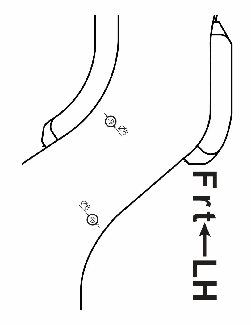
Frt
LH

Frt
RH