sage: generatingapplications with umland componentsndykman/thesis/draft-1-4.pdf · case tool,...
TRANSCRIPT

SAGE: GENERATING APPLICATIONS WITH UML AND
COMPONENTS
by
Nathan Dykman
A thesis submitted to the faculty of
The University of Utah
in partial fulfillment of the requirements for the degree of
Masters of Science
Department of Computer Science
The University of Utah
December 1998

Copyright © Nathan Dykman 1999
All Rights Reserved

ABSTRACT
This thesis presents a prototype application generation tool, SAGE (SeaBank
Application Generation Environment) that demonstrates how the Unified Modeling
Language (UML) can be used as a domain specific application generation language for
component or framework-based software development. The UML-based extensible
CASE tool, Rational Rose, was extended to create SAGE for developing applications that
use the experimental SeaBank framework.
We have learned that the extensibility features of UML combined with a powerful
UML-based CASE tool allow new tools to be created that support reuse-based software
development with domain-specific components and frameworks. This leads to tools that
automate the customization and reuse of software components. These tools help shorten
the learning curve involved in reuse-based software development and insure that a higher-
level model of the application represents the software components and frameworks in a
consistent manner by automating the generation of components from models. By
examining how SAGE uses UML, Rational Rose and the SeaBank framework, we can
discuss of the advantages and disadvantages of each and gain insights into how they could
be improved to work better together.
Reusable software components and frameworks play an important role in modern
software development. While software reuse demands significant changes in management

v
and corporate culture to be effective, tools like SAGE are important in insuring proper
adoption of reuse ideas and enabling effective reuse-based software development.

To Family and Friends
for their constant support

TABLE OF CONTENTS
ABSTRACT.......................................................................................................................iv
LIST OF FIGURES............................................................................................................ ix
ACKNOWLEDGEMENTS ................................................................................................ x
CHAPTER 1 INTRODUCTION......................................................................................... 1
1.1 The Software Crisis and Magic Bullets................................................................... 31.2 Why SAGE was Developed .................................................................................... 51.3 Thesis Organization................................................................................................. 7
CHAPTER 2 PROJECT OVERVIEW ............................................................................... 9
2.1 Traditional and Reuse-Based Views of Development ............................................ 92.2 Software Components and Frameworks................................................................ 15
2.2.1 Software Components .................................................................................. 162.2.2 Software Frameworks................................................................................... 162.2.3 Software Kits: Enabling Effective Software Reuse ..................................... 17
2.3 Technologies Used in SAGE................................................................................. 192.3.1 SeaBank........................................................................................................ 202.3.2 UML............................................................................................................. 21
2.3.2.1 UML Class and Component Diagrams ............................................... 232.3.2.2 UML Extensibility Features ................................................................ 26
2.3.3 Rational Rose ............................................................................................... 282.3.3.1 UML Extensibility Features in Rational Rose .................................... 30
CHAPTER 3 THE SAGE DEVELOPMENT TOOL ....................................................... 36
3.1 SeaBank Task Model Components ....................................................................... 363.1.1 Frames .......................................................................................................... 383.1.2 Manual Generation of SeaBank Task Models.............................................. 40
3.2 Generating SeaBank Task Models with SAGE..................................................... 443.2.1 Creating SeaBank Models and Generating Components ............................. 46
3.3 SAGE Design and Implementation ....................................................................... 553.3.1 The SeaBank Generation Metamodel........................................................... 563.3.2 Design and Implementation of SAGE with UML and Rose ........................ 60
3.3.2.1 SAGE Implementation Effort and Costs ............................................. 64
viii
3.4 Summary ............................................................................................................... 65
CHAPTER 4 PROJECT EVALUATION......................................................................... 66
4.1 Evaluation of UML ............................................................................................... 674.1.1 UML Advantages ......................................................................................... 684.1.2 UML Disadvantages..................................................................................... 69
4.2 Evaluation of Rose ................................................................................................ 724.2.1 Rational Rose Advantages ........................................................................... 734.2.2 Disadvantages of Rational Rose................................................................... 74
4.3 Evaluation of SeaBank and Coffee ....................................................................... 764.3.1 SeaBank and Coffee Advantages ................................................................. 774.3.2 SeaBank and Coffee Disadvantages............................................................. 78
4.4 Comparison of SAGE and Composer ................................................................... 81
CHAPTER 5 FUTURE DIRECTIONS AND RELATED WORK .................................. 84
5.1 Future Directions................................................................................................... 845.1.1 Tools for Component Development and Generation ................................... 845.1.2 Supporting Reuse-Based Process Frameworks ............................................ 885.1.3 Metamodels and Tool Development ............................................................ 90
5.2 Related Work......................................................................................................... 915.2.1 Sterling COOL Tools ................................................................................... 915.2.2 ObjectTime Developer and ROOM ............................................................. 925.2.3 IBM ComponentBroker and San Francisco Framework .............................. 935.2.4 Visio ............................................................................................................. 945.2.5 Microsoft Visual Modeler and Visual Studio .............................................. 955.2.6 Rational Rose and RoseLink Partners .......................................................... 96
CHAPTER 6 CONCLUSIONS......................................................................................... 97
APPENDIX A GLOSSARY ........................................................................................... 101
APPENDIX B MORE ON UML .................................................................................... 106
APPENDIX C MORE ON SOFTWARE REUSE.......................................................... 109
APPENDIX D MORE ON COMPONENTS AND FRAMEWORKS........................... 115
APPENDIX E MORE ON SEABANK........................................................................... 120
REFERENCES................................................................................................................ 122

LIST OF FIGURES
Figure Page
Figure 2.1 Traditional View of Software Development ................................................... 11
Figure 2.2 Reuse-based View of Software Development................................................. 13
Figure 2.3 A UML Class .................................................................................................. 23
Figure 2.4 A UML Component ........................................................................................ 25
Figure 2.5 A UML Class with a Stereotype...................................................................... 26
Figure 2.6 Objectory Process Classes, With and Without Stereotype Icons .................... 27
Figure 2.7 Rational Rose Environment ........................................................................... 31
Figure 2.8 Rational Rose Specification Dialog Box......................................................... 32
Figure 2.9 Specification Dialog with IDL Properties Selected......................................... 35
Figure 3.1 SeaBank Manual Component Development Process ...................................... 40
Figure 3.2 SeaBank Component Generation Process with SAGE.................................... 45
Figure 3.3 Component Specification Dialog with Viewer Properties ............................. 47
Figure 3.4 CreateOrder TM Class Model ......................................................................... 48
Figure 3.5 Class Specification with Action Property Set Shown ..................................... 51
Figure 3.6 Table of SAGE Model Properties and Default Values.................................... 54
Figure 3.7 SeaBank Generation Metamodel..................................................................... 57
Figure 3.8 SAGE UML Class Model ............................................................................... 60
Figure 3.9 UML Sequence Diagram for Code Generation ............................................... 63

ACKNOWLEDGEMENTS
My thanks to Professor Robert Kessler and Professor Martin Griss for their support of
my research while working with the Component Software Project at the University of
Utah and as an intern at HP Labs. Without their support, this thesis would not be possible.
My thanks to Professor John Carter and others at the Computer Science Laboratory at
the University of Utah for allowing me the opportunity to first do research at the
University of Utah while pursuing my bachelor’s degree. The experience convinced me to
continue my studies and obtain a graduate degree.
My thanks to Professor Joseph Zachary, who gave me my first position in the
Computer Science Department as a Teaching Assistant. The position was a great learning
experience and a great help to my studies.
And, finally, to the many other people that have supported me in my academic career,
my sincerest thanks.

CHAPTER 1
INTRODUCTION
Developing software is hard. Software impacts almost every aspect of modern society
and the demands of an information-based economy have created an intense demand to
create better, larger, cheaper and more effective software that creates, manages and
disseminates information. One need only look at the astonishing growth of the World
Wide Web and personal computing to see the increasing impact of software on society.
New cars depend on software to run efficiently. The dial tone of a telephone depends on
millions of lines of source code. Modern utility companies require large computer
systems to manage the distribution of power, natural gas, etc. Banks are dependent on
software to track and manage assets. Software is everywhere, and is becoming more and
more pervasive in everyday life.
Despite the pervasive and important nature of software, software development is a
young and immature discipline, compared to many other engineering disciplines. In many
organizations, more software development projects fail than succeed. Projects often run
over budget or over schedule; overruns of more than 50% in cost or schedule are
common. Additionally, software is often delivered with fewer features than requested,
with critical features missing or unreliable, and with numerous defects that require costly
maintenance. In the book Software Runaways [1], Robert Glass discusses a number of
projects that were 100% over budget and schedule, and additionally failed to deliver any
2
software, or delivered significantly less functionality than originally planned. For
example, development of new software for the FAA Air Traffic Control system incurred
more than 2 billion dollars in costs without delivering any software that is currently used.
The old software system is still in use, despite increasing numbers of failures and the
extreme difficulty in maintaining the old hardware. Currently, software development is a
very difficult, costly, and unpredictable undertaking.
However, as Robert Glass is quick to point out, software has also had amazing
successes, and software development is slowly becoming more predictable and effective.
More organizations are able to create software in a more predictable manner, and new
ideas and technologies in software engineering hold great promise in making software
development easier and more effective.
More people are becoming aware of the need for a disciplined, predictable approach
to software development. Some organizations consistently and predictably create high-
quality software in a cost-effective and timely manner. These organizations often create
critical software applications, in which life or property may be at stake if the software
fails to work correctly. These organizations continually succeed to create highly reliable
and effective software within a reasonable time and cost budget. However, these
organizations are still a small minority in the software industry. Most of the industry is
still faced with what is termed “The Software Crisis.” [2]

3
1.1 The Software Crisis and Magic Bullets
The long-term inability of organizations to create software in a predictable, efficient
and timely manner has been called “The Software Crisis.” Despite many attempts to
create a “Magic Bullet” that solves the Software Crisis, no one simple solution has been
found, and no one simple solution will likely ever be found. [3, 4]
Software development is a complex web of technical, business, personal and
sociological factors that are difficult to balance, to manage and to predict. Sociological,
business, personal factors and other issues must be managed properly, or they will
overwhelm the project. Complex technical problems must be addressed and resolved in a
timely manner. The right set of software tools and processes must be discovered and used
properly to ensure developer productivity and new tools to support the project may need
to be created. Interoperation with third-party software or legacy systems needs to be
addressed. Software must be tested to improve quality, and to discover defects in the
software. There are even more development factors to taken into consideration and
managed. All this must be in done with specific budget and business goals, and time to
market is often critical.
Discovering the right balance of process, tools, management and people is difficult,
and this balance is critical for success. Furthermore, this balance changes for each new
project, and changes as the project progresses. Software engineering is the study of
techniques and tools for quickly discovering and maintaining this balance, and helping
individuals become more effective and productive software developers. [5, 6]
In 1986, Fred Brooks asserted in the classic paper “No Sliver Bullet” [4] that no
single tool or technology would provide an order-of-magnitude gain in software
4
productivity, reliability, or simplicity in the next ten years. Given the number of factors
involved in software development, this is not surprising. Many years after this assertion
was made, it has held true, and will be likely remain true for many years to come. Brooks
notes that software development will always have an essential complexity that must be
always addressed and managed, and no tool can completely address the complexity of
software development.
Unfortunately, Brooks’ assertion that no magic bullet exists is often misinterpreted as
“tools can not make a difference.” As Brooks himself notes, tools do make an important
difference in managing and overcoming the conceptual difficulties inherent in software
development. [3] Brooks rejects the notion that a “software cure-all” will ever be found;
Brooks does not say that tools have little or no impact on software development.
To further clarify how tools can help software development, Will Tracz describes the
idea of a “Golden Gun” of software development, in which people, tools, and process are
carefully combined together and managed to create quality software. [7] Tracz notes that
this well-coordinated set of tools, process, people and management has a profound impact
on software productivity and quality. Tracz also notes that developers often do not have
the tools they need to create good software, and like craftsmen, they must have the proper
tools to create quality software products.
Tracz’s standard set of tools is comprehensive, including tools for documentation
management, code repositories, modeling, task management, metrics collection and
analysis, source code management, integrated development environments, code analysis,
and other tools. While these tools can be expensive, a proper investment in tools has a
5
positive return on investment and provides increased productivity, and Tracz believes
tools are essential parts of creating high-quality reusable software.
Another idea that Brooks, Tracz and others believe that will have a great impact is
software reuse. Software reuse is the use and development of software artifacts that are
used over and over again in a number of different, but related software projects. Instead
of “reinventing the wheel” for each new project, the project reuses high-quality, well-
tested frameworks, components, designs and architectures for each new software
application. Software reuse is most effective when the reusable software artifacts are
developed for and used in a specific software domain. [7, 8]
1.2 Why SAGE was Developed
SAGE is a specific example of how tools and reusable software components and
frameworks can work together to simplify application development. More specifically,
SAGE is a tool that simplifies the development of new SeaBank components.
The SeaBank framework, developed at Hewlett-Packard Labs, contains a number of
software components that must be customized to fit the requirements of each new
application. This customization process is controlled by customization files that contain
parameters that specify the interfaces and associations of each component and the
component parts that the components use to implement the component functionality.
The customization files for large sets of components and shared component parts are
hard to develop and maintain. A tool was needed in order to make the development of
SeaBank applications more manageable by making development of customization files
much easier and more robust. The first version of this tool was called Composer.

6
Composer was based on an experimental visual programming environment CWAVE
and a set of wizards that automated the generation of SeaBank customization files from
visual models of SeaBank components. While Composer did indeed help the developers
create new customization files for components, it had a number of deficiencies.
Composer used an experimental and sometimes unstable platform. The tool used a hard
to maintain combination of C++ code and scripts to generate component files. Also,
developers could only model SeaBank components in a special notation. Developers
could not model other aspects of the software. SAGE was developed to address these
issues.
SAGE creates the customization files for SeaBank components by translating UML
(Unified Modeling Language) models. UML is a standard notation and language for
graphically modeling various aspects of object-oriented software. The UML contains a
number of features that allow developers to annotate models with additional project-
specific information that is not easily modeled in the core notation. [9, 10]
SAGE is implemented as a small, easily maintained extension to Rational Rose.
Rational Rose is a stable and mature commercial CASE tool that supports the design and
implementation of software using UML. Developers can use the combination of SAGE
and Rational Rose to model all aspects of a SeaBank-based application using SAGE to
generate the customization files for the SeaBank component, and Rational Rose will
create skeleton code that represents other classes in the software design. [11]
Even more important than helping developers to create new SeaBank applications,
SAGE gives a number of important insights into the advantages and disadvantages of

7
UML, Rational Rose and SeaBank for reuse-based software development with
components and frameworks.
Since SAGE uses many features from UML, Rose, and SeaBank as possible, some
limitations of each technology were discovered during the development of SAGE. This
information gives some insights into improvements for UML, Rose and SeaBank, and
ideas on how future technologies should be structured to effectively support reuse-based
software development. Since many of these technologies are relatively new or have new
features, this information sheds some light into the effectiveness of each technology.
In short, SAGE was developed as a more effective tool for SeaBank application
development, and as a learning experience to explore the advantages and disadvantages of
UML, Rational Rose, and SeaBank technology. The information gained in the
development of SAGE contains important insights in how each technology in SAGE
supports reuse-based software development with components and frameworks.
1.3 Thesis Organization
Chapter 2 gives the necessary background information on this thesis and SAGE. The
ideas that motivate this thesis are discussed in more detail and the various technologies
that are used in this thesis are discussed in more detail. Chapter 3 discusses how to create
SeaBank applications with SAGE, how SAGE was designed and implemented, and how
UML and Visual Basic were used to rapidly prototype and create SAGE.
Chapter 4 discusses the strengths and weakness of SeaBank, UML, and Rational Rose
for creating component-based applications and for creating component-based application
tools based on the experiences in developing SAGE. Chapter 5 discusses related work to
8
this thesis, and also presents potential extensions to this work. Chapter 6 summarizes the
thesis.
The appendices include background information and additional information on topics
discussed in this thesis. Appendix A is a short glossary of terms. Appendix B gives a brief
introduction to UML. Appendix C presents more information on software reuse.
Appendix D has more information on software component and framework technologies.
Appendix E discusses the SeaBank framework in greater detail, and Appendix F contains
more information on CASE tools.

CHAPTER 2
PROJECT OVERVIEW
This chapter presents the ideas and technologies that motivated this thesis and
contributed to the creation of SAGE. Section 2.1 presents the motivation behind this
thesis by presenting a traditional view of software development and then contrasting it
with a reuse-based view of software development. This section also discusses ideas in
software reuse. Section 2.2 discusses software component and frameworks in more detail,
and presents the idea of a software kit. Section 2.3 discusses the various tools used to
develop SAGE. CASE tools, UML, Rational Rose, SeaBank are all presented in more
detail.
2.1 Traditional and Reuse-Based Views of Development
Currently, most software is created from scratch. While almost all programmers reuse
a little code from project to project, the majority of software in use today is mostly made
from new code. Proponents of software reuse note that this is not an effective state of
affairs. Software reuse advocates point out the need for high-quality assets to be used
across many projects and the need to not redevelop software time and time again. Instead
of focusing on just one application at a time, software reuse advocates developing a
broader view of software development and creating reusable software for domain-specific
families of software. [7, 12-14] For example, HP has a reuse program for instrument
10
software, where components are developed and reused in the firmware of a number of
hardware products. The Ericsson AXE program used a common set of telecommunication
support components to be used in a set of telephone switches. [15] In both cases, the
reuse programs have greatly improved the software development process.
Figure 2.1 gives a graphical picture of a software development process based on the
Rational Unified Process framework. [16, 17] The software development process begins
with gathering software requirements and creating a formal model of the requirements in
the form of use-cases and actors. Use-cases are a description of the high-level flows of
actions in the system. Actors represent the external users of a software system that use the
various use-cases to perform various tasks. In UML, use-cases appear as ellipses, and
actors appear as stick figures.
Then an analysis model is created from a subset of the requirements. This model
contains a set of abstract classes that capture the architecture of the software. The
architecture is captured by using three types of classes: Boundary classes, which represent
the interfaces to external users, entity classes which represent the state and resources used
by the software, and control classes, which coordinate actions between other objects. In
UML, boundary objects are shown as circle with a T on one side, entity objects are shown
as a circle with a line below it, and control objects are shown as a circle with an arrow.
The analysis model is refined into a design model. The design model contains the
classes that represent the actual implementation of the software. This design model can be
directly refined into code. In UML, classes are represented as rectangles that are split into
three panes. The code is tested (not shown), and the cycle repeats until the software is
completed.

11
Figure 2.1 Traditional View of Software Development
Even the previous figure presents a more orderly and disciplined view of software
development than many organizations use. In many cases, requirements are gathered in an
informal and chaotic manner, and requirement models are not created or maintained.
Requirements get out of sync with software designs or code, or new requirements
constantly disrupt the development process. The requirements never become stable
enough to give a reasonable picture of the software functionality. High-level analysis and
architectural models are often informal and rushed, and in some cases are skipped
entirely. Design models may not be made, and are certainly not kept in sync with the
code. A lot of effort is spent in writing code, and defects and problems that arise during
implementation are not traced back to the higher levels of the software design. Errors in
Requirements Model Analysis Model
Implementation Model
class foo{
// your code here...}class bar{
// your code here...}
Components
Components added atimplementation time,developer adds themby hand, in adhocmanner.
Design Model
// Cut and Paste// Code
// Informal// libraries
// Third party// code
12
the requirements or design are often not found until code testing, and are extremely costly
to find and fix. The lack of a coherent design lengthens the coding and integration
process. Many defects are still present in the software, and these defects are very costly to
fix as well. So, even software organizations that use models and a controlled development
process are better off than companies that practice chaotic software development. In
chapter 3 of [18], Steve McConnell discusses the common myths and advantages to
software process.
However, even the orderly and controlled development process presented in Figure
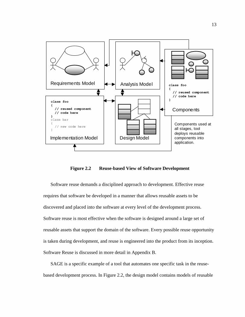
2.1 can be further improved. Figure 2.2 shows a model of software development based on
software reuse.
In this figure, reusable assets are bold and shaded. Instead of creating all the models
and code from scratch, they are reused whenever possible. Reusable requirements are
available that represent common activities in the software domain, and these requirements
are well documented and understood. The analysis model includes reusable high-level
objects that represent common entities, services, interfaces and architectures in the
software domain. The design model includes a number of classes that represent reusable
components and frameworks. The implementation uses these reusable components,
frameworks and other reusable code as much as possible. All the modes and reusable
assets are maintained and documented in a consistent manner, and new reusable assets are
constantly being researched and developed for future software projects.
13
Figure 2.2 Reuse-based View of Software Development
Software reuse demands a disciplined approach to development. Effective reuse
requires that software be developed in a manner that allows reusable assets to be
discovered and placed into the software at every level of the development process.
Software reuse is most effective when the software is designed around a large set of
reusable assets that support the domain of the software. Every possible reuse opportunity
is taken during development, and reuse is engineered into the product from its inception.
Software Reuse is discussed in more detail in Appendix B.
SAGE is a specific example of a tool that automates one specific task in the reuse-
based development process. In Figure 2.2, the design model contains models of reusable
Requirements Model Analysis Model
Design ModelImplementation Model
class foo{
// reused component// code here
}class bar{
// new code here}
Components used atall stages, tooldeploys reusablecomponents intoapplication.
Components
class foo{
// reused component// code here
}

14
software classes. These classes are then placed in the implementation model as reusable
code. This process is normally done manually by developers. SAGE automates this
process between the design model and the implementation model by automating the
translation of SeaBank component designs into SeaBank component implementations.
The developer models in UML the various SeaBank classes and components and
annotates them with the information necessary to generate the new application-specific
components. This ensures that the design and implementation models are consistent and
that developers use SeaBank components properly and effectively in SeaBank
applications.
Figure 2.2 shows that in order for reuse to be maximally effective, applications must
be developed with reusable components in mind at every step. This is true for SeaBank
application development as well. In order to insure that the new SeaBank-based
application uses the SeaBank framework as much as possible, the application must be
designed around the common set of components SeaBank provides. Developing models
of the software, from requirements down to designs, is critical for SeaBank development.
Without proper modeling and controlled development, it will be much more difficult to
create an effective SeaBank application. SAGE is an additional incentive for developers
to create models, as the design models can be used to generate the necessary
customization files, freeing developers from creating the files by hand, and SAGE insures
that the designs are consistent with the initial implementation and code.

15
SeaBank contains both a framework, which provides common mechanisms for
distribution and management of individual components, and components, which represent
and implement common tasks and concepts in the banking environment. The next section
discusses components and frameworks in more detail.
2.2 Software Components and Frameworks
The most common reusable software technologies in use today are software
components and frameworks. Components are reusable software packaged in a manner
that supports a standard means of using, interfacing and integrating the component with
other components and applications. Frameworks are incomplete software architectures or
class libraries that are completed to form new applications. Currently, components are
more commonly used than frameworks, but frameworks are still a very important and
powerful reuse technology. Combining components and frameworks together enables
rapid application development and effective software reuse.
Software components and frameworks are both ways of structuring and packaging
software for reuse. Components and frameworks differ in how they contribute to the
creation of software applications. Components provide ready-to-use functionality that is
easily added to a software application though a standard interface. Components contribute
to software development by allowing complex functionality to be quickly incorporated
into software. Component technologies also provide a standard means of accessing and
using a set of components.
Software frameworks provide the “skeleton” of an application. Frameworks provide
the infrastructure and architecture for applications. To create new applications, the
16
framework is completed with code and components that implement the additional
software functionality that is not provided by the framework.
2.2.1 Software Components
It is not easy to formulate a precise definition of software components. Components
are a relatively new idea and the infrastructures and tools for components are rapidly
changing and evolving. Despite this, the intent and purpose of software components is
fairly clear. Components are software that is packaged to provide a ready-to-use set of
functionality that is easily imported into a software application. Components, in order to
be effective, must be standardized, flexible, robust, and provide useful and significant
functionality to applications.
Many component technologies are currently available, the most common component
technologies being COM from Microsoft, JavaBeans from Sun, and CORBA from the
OMG. [19-27] Components are discussed in more detail in Appendix B.
2.2.2 Software Frameworks
The main difference between software frameworks and software components is that
software frameworks must be completed to be functional or useful. A software
component is an independent, complete piece of software that can be used as-is. A
software framework requires developers complete parts of the framework to create
complete software. For example, the SeaBank framework provides the infrastructure for
managing, creating and using objects and components on distributed servers, but these
servers do nothing without the developer adding objects and components.
17
While frameworks do not standalone, they can be very powerful tools for developers.
For example, the SeaBank framework allows developers to focus solely on developing
new code and components to support the activities of the business, and SeaBank takes
care of distributing the objects, enforcing a security policy for object access, support
transactions and atomic update for objects, and so on. If developers had to create this
code for each object themselves, the development task would be much harder, if not
impossible.
Another important benefit of frameworks is that they provide well-tested application
architectures and designs. Frameworks help ensure that an application has a robust and
scalable architecture that is easily extended. The effort in creating effective software
architectures is quite large, and frameworks can be used to reduce these costs by
providing a ready-made architecture, or to help ensure that the investment in software
architecture is spread across several projects. Frameworks are discussed in more detail in
Appendix B.
2.2.3 Software Kits: Enabling Effective Software Reuse
The combination of frameworks and components to develop applications has great
potential. However, the learning curve for programming with frameworks and
components is often steep. Correct usage and understanding of frameworks or
components is crucial for developing effective applications.
To reduce this learning curve, and to make frameworks and components even more
effective, a software kit can be used. A software kit contains specialized tools, examples,

18
documentation, generation languages, and other technologies that support and accelerate
development with frameworks and components.
It is easier to build things from pre-made parts put together in a kit than from scratch.
For example, building a pre-manufactured desk that is sold in a store is much easier than
building a desk from plain wood, nails and glue. While making software from pre-made
parts is certainly not as simple as making a prepackaged desk, having software parts that
are easy to assemble together can make software development easier. A software kit is a
set of components, frameworks, documents, guidelines, examples and specialized tools
bundled together to help developers rapidly create applications in a specific domain.
The idea of a kit is fairly simple, but kits are not easy to implement. If you have a
specific software domain that has the potential for producing a family of applications, you
can consider creating a set of parts, tools, etc. that help you create those applications
quickly. Kits require careful domain analysis to be effective, and this domain analysis can
be difficult. Applications outside the kit domain may be able to use some parts from the
kit, but overall the kit is not useful for developing those applications, so the domain must
be chosen carefully.
If the domain is too broad, the kit will be too complex; if the domain is too narrow
then the kit can only be used for a couple of applications and is not cost-effective. If the
domain is too large, the kit may be too complicated and complex to be used effectively. If
the parts are wrong and do not address the demands of the domain properly, then the kit
will not be usable in that domain. Coming up with the right set of parts is difficult and
requires careful analysis and development.

19
SAGE is an example of a tool that could be a part of a hypothetical SeaBank
application kit. SAGE takes the annotated application designs and customizes SeaBank
components for an application. Having tools like SAGE is an important addition to any
kit, as they automate the process of translating designs into implementations that properly
reuses the frameworks and components in the kit. Kits are discussed in more detail in [8,
28, 29].
2.3 Technologies Used in SAGE
SAGE was created as an extension to a powerful UML CASE (Computer Aided
Software Engineering) tool, Rational Rose. This allows developers to model many other
aspects of the application, and not just the SeaBank application components.
Most CASE tools are generic, which means they apply to any kind of software
project, and are not specialized to any particular software domain. Most CASE tools can
create code that represent the class interfaces and associations present in the class designs
in software models. While this helps ensure consistency between the design and
implementation, the generated code is only a small part of the total software application.
The developer must create a large part of the code before the application is completed.
Other design models may guide the developer in implementing the software.
Custom CASE tools, unlike generic CASE tools, trade generality for power. By
limiting the tool to a specific area, the tool can generate more fully functional work-
products from models. For example, a database-modeling CASE tool can create a
working database directly from a database diagram. The developer doesn’t need to finish
creating the database tables; the tool completely automates the implementation process.

20
Custom CASE tools are tools that can take advantage of reusable software or software
domains to create more complete applications from software models, but they are limited
to one set of components or a particular software domain.
Since SAGE is an extension to a generic and powerful CASE tool, developers can:
generate skeletal classes in the application, create and deploy new databases, use and
import designs of other components and frameworks, and use other third-party tools that
work with Rational Rose to help application development. In short, the integration of
SAGE into the Rational Rose environment allows developers to not only develop the
SeaBank elements of the application, but to design and develop the other parts of the
application as well.
This section presents the various tools and technologies to create SAGE. As we
discussed in the previous section, tools can play an important role in component,
framework and kit-based development. Section 2.3.1 discusses the SeaBank frameworks
and components in more detail and briefly discusses how SeaBank applications are
developed. Section 2.3.2 discusses UML, a standard OO modeling language, which is
rapidly becoming the standard OO model notation. Section 2.3.3 discusses Rational Rose,
a widely used and extensible CASE tool that supports the UML.
2.3.1 SeaBank
SeaBank is a banking-domain framework that provides components for task
management, reporting, business logic, and database access as they relate to the transfer
and management of monetary instruments. SeaBank provides mechanisms for
distribution, controlled access and transactional management of these components. [30]
21
SeaBank applications are built from customized SeaBank components that implement
the application requirements. Each component consists of a number of standardized parts.
These parts represent a collection of classes that implement certain aspects of the
component functionality. For example, the SeaBank Task Model component has the
following parts: Actions (what the users can do), Viewers (what the users are presented),
Business Objects (what business rules the component uses), and Task Model (how the
other component parts work together).
In order to generate new application-specific components, a file is needed that
contains the various information that specify the structure of the component parts and the
features the component supports with respect to the application requirements.
SAGE automates the tedious task of creating the necessary parameter files by
allowing designers to create a UML model that contains all the necessary information.
SAGE makes it much easier to share parts between components, to update component
parts and component interfaces, and to manage the files that are required to make new
SeaBank components.
2.3.2 UML
Software Methodologies (or Methods) are systematic descriptions of how software is
to be designed and modeled. Methods first appeared with the rise of structured
programming. Structured programming restricted the use of certain code constructs (goto
statements, non-local branches and jumps, etc.), encouraged the use of abstract data types,
and focused on top-down development and decomposition of programs. Structured
Analysis and Design Methods (SADM) documented a systematic way of designing
22
programs that followed the principles of structured programming. One aspect of these
methods is that they used graphical notations to express the design of programs.
Each different structured method had its own notation and set of diagrams, making
them incompatible. Also, the limitations of structured programming for software
development combined with the rise in OO programming gave rise to OO methods meant
that structured methods never caught on.
For a while, it appeared that OO methods would soon suffer the same fate as their
structured method counterparts. Each OO method had its own notation and diagrams. [31-
34] Different methods covered different parts of software development, but they often
overlapped in incompatible ways. Therefore, OO methods, like structured methods, were
incompatible.
To address this problem, the Object Management Group (OMG) submitted a Request
For Proposal (RFP) on a standard object modeling and diagramming language. The
authors of the three most popular OO methods at the time, Grady Booch (Booch method),
James Rumbaugh (OMT) and Ivar Jacobson (OOSE), all at Rational Software
Corporation, came together and worked with a number of other organizations to create
the Unified Modeling Language (UML) standard. The UML was based on work already
underway at Rational Software to combine the Booch, OMT, and OOSE notations. UML
1.1 was adopted as an OMG standard in 1997, making it the de-facto notation standard
for OO modeling. [9, 10, 35]
The UML standard defines a common notation and semantic meaning to OO models.
The software design is represented in a common graphical notation. The UML defines a
number of views and diagrams that model the software at various degrees of abstraction.
23
The UML has software diagrams that represent software requirements, static and dynamic
views of the software design, and physical deployment and packaging of software.
However, in this section, we concentrate on three features of UML. UML class diagrams,
UML component diagrams, and the UML extensibility features, stereotypes and
properties. UML is discussed more in Appendix D.
2.3.2.1 UML Class and Component Diagrams
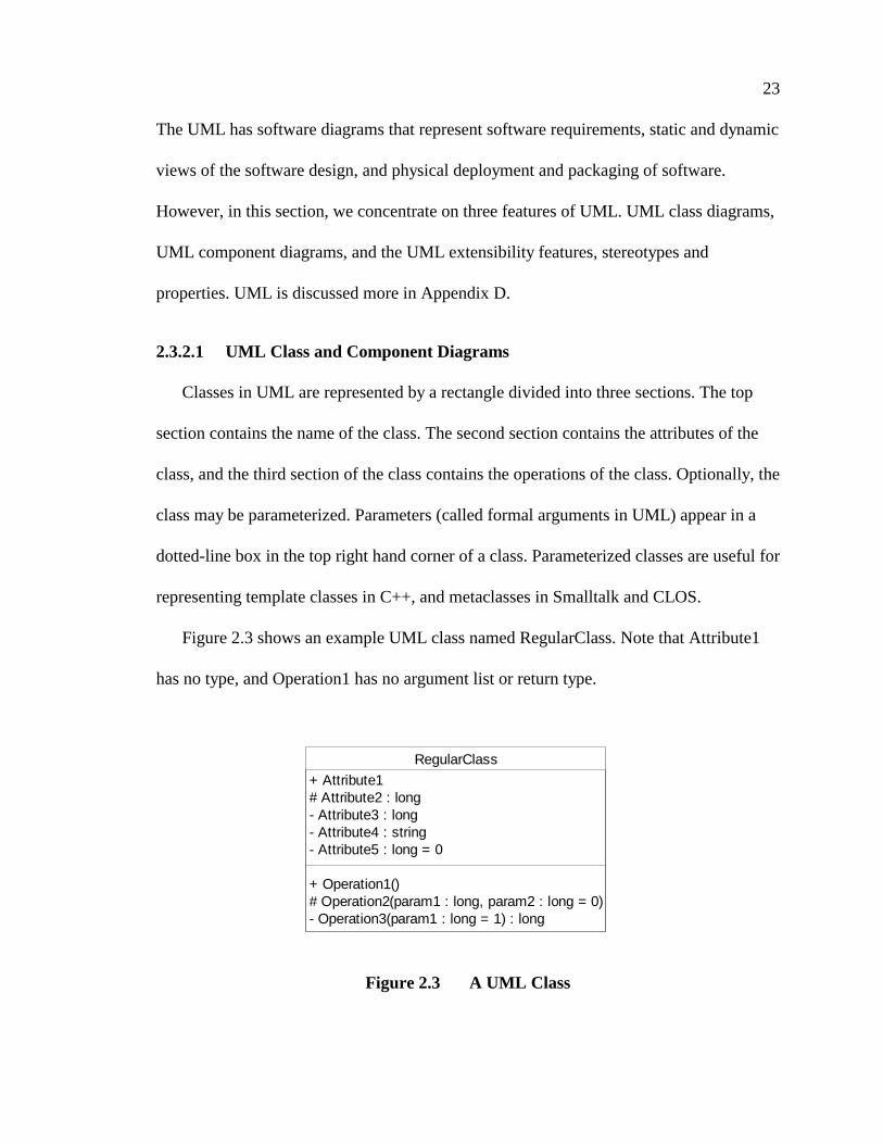
Classes in UML are represented by a rectangle divided into three sections. The top
section contains the name of the class. The second section contains the attributes of the
class, and the third section of the class contains the operations of the class. Optionally, the
class may be parameterized. Parameters (called formal arguments in UML) appear in a
dotted-line box in the top right hand corner of a class. Parameterized classes are useful for
representing template classes in C++, and metaclasses in Smalltalk and CLOS.
Figure 2.3 shows an example UML class named RegularClass. Note that Attribute1
has no type, and Operation1 has no argument list or return type.
Figure 2.3 A UML Class
RegularClass
+ Attribute1# Attribute2 : long- Attribute3 : long- Attribute4 : string- Attribute5 : long = 0
+ Operation1()# Operation2(param1 : long, param2 : long = 0)- Operation3(param1 : long = 1) : long
24
The visibility of the attributes and operations appear at the very front. A ‘+’ means
public visibility, ‘- ’ means private visibility and ‘#’ means protected visibility. For
example, the class in Figure 2.3 could be translated into the following C++ class:
class RegularClass{
// No Attribute1, since it does not have a type.public:
// Assume we must have a public default constructor// to set the value of Attribute5 to be zero,// as the UML class says.RegularClass() : Attribute5(0) {}void Operation1(void);
protected:long Attribute2;void Operation2(long param1, long param2=0);
private:long Attribute3;string Attribute4;long Attribute5;
};
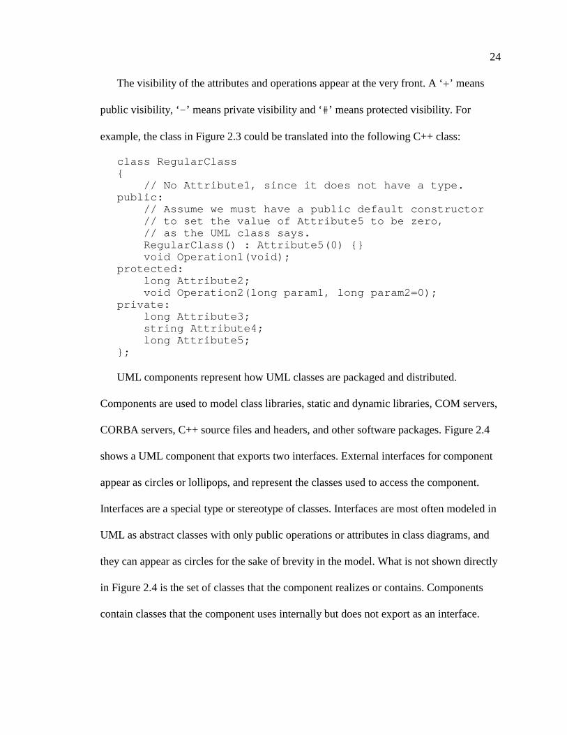
UML components represent how UML classes are packaged and distributed.
Components are used to model class libraries, static and dynamic libraries, COM servers,
CORBA servers, C++ source files and headers, and other software packages. Figure 2.4
shows a UML component that exports two interfaces. External interfaces for component
appear as circles or lollipops, and represent the classes used to access the component.
Interfaces are a special type or stereotype of classes. Interfaces are most often modeled in
UML as abstract classes with only public operations or attributes in class diagrams, and
they can appear as circles for the sake of brevity in the model. What is not shown directly
in Figure 2.4 is the set of classes that the component realizes or contains. Components
contain classes that the component uses internally but does not export as an interface.
25
Figure 2.4 A UML Component
In SAGE, the SeaBank component parts are represented as UML classes, and the
actual SeaBank component is modeled as a UML component that contain the classes that
represent the component parts. SeaBank components do not have interfaces in the model,
as the interfaces are completely determined by the component parts, and are not separated
in the SeaBank framework.
In SeaBank, we need to differentiate between an Action part, a Viewer part, a
Business Object part and a Task Model part, which are all modeled as UML classes. In
addition, we also have information that is not easily represented as an attribute or an
operation of the class. To solve these problems, we use the UML extensibility features,
stereotypes and properties. Stereotypes are a means of marking a UML element as having
a special subtype. Properties are an arbitrary set of key-value pairs that can be attached to
any UML element in a model. Stereotypes are used to differentiate each type of SeaBank
component part, and properties are used to store the information that is not represented as
a class attribute or a class operation. The next section discusses stereotypes and properties
in more detail.
Component
Interface1
Interface2
26
2.3.2.2 UML Extensibility Features
Every element in a UML model can be extended with a stereotype. A stereotype states
that the element is a subtype of the general model element, and has additional semantic
meaning. In addition, a stereotyped element may have a special appearance in the UML
model. Stereotypes allow models to extend UML semantics in a controlled manner.
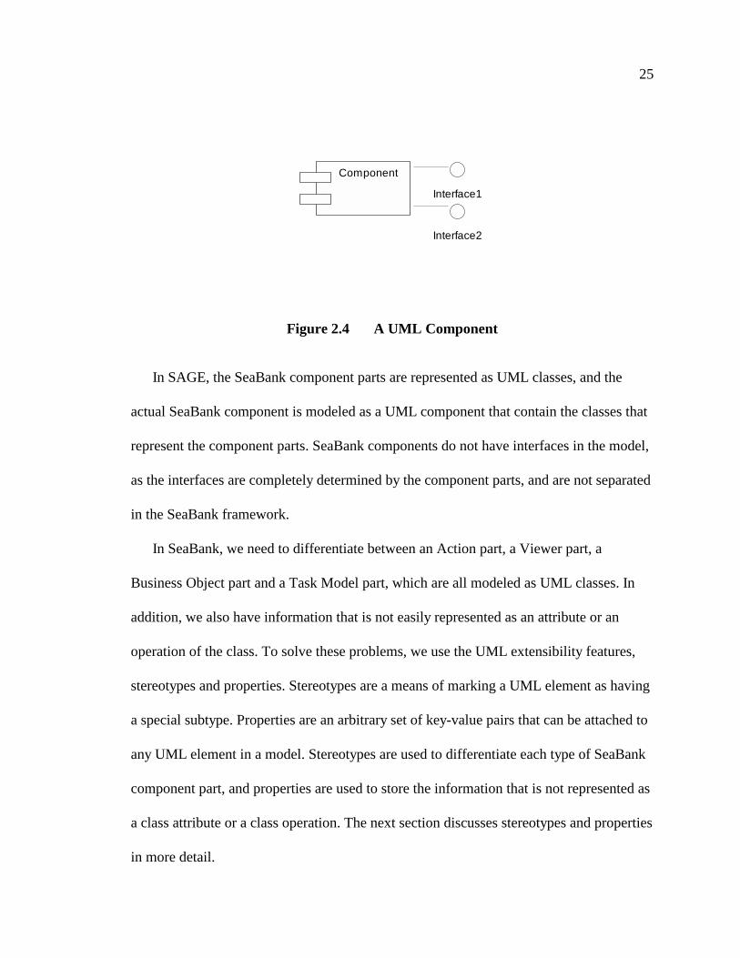
For example, let us assume that we want certain classes in our model to represent
CORBA IDL interfaces, not C++ classes. We define a stereotype IDL, and mark all the
IDL classes with that stereotype. Figure 2.5 shows an example. Note that the stereotype is
bracketed by guillemets («»). Stereotypes may also be bracketed as (<<>>), if guillemets
aren’t available or plain text must be used.
Figure 2.5 A UML Class with a Stereotype.
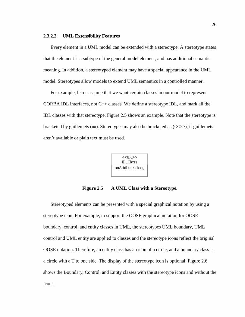
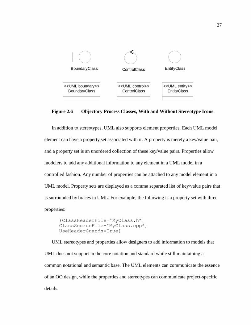
Stereotyped elements can be presented with a special graphical notation by using a
stereotype icon. For example, to support the OOSE graphical notation for OOSE
boundary, control, and entity classes in UML, the stereotypes UML boundary, UML
control and UML entity are applied to classes and the stereotype icons reflect the original
OOSE notation. Therefore, an entity class has an icon of a circle, and a boundary class is
a circle with a T to one side. The display of the stereotype icon is optional. Figure 2.6
shows the Boundary, Control, and Entity classes with the stereotype icons and without the
icons.
IDLClass
- anAttribute : long
<<IDL>>
27
Figure 2.6 Objectory Process Classes, With and Without Stereotype Icons
In addition to stereotypes, UML also supports element properties. Each UML model
element can have a property set associated with it. A property is merely a key/value pair,
and a property set is an unordered collection of these key/value pairs. Properties allow
modelers to add any additional information to any element in a UML model in a
controlled fashion. Any number of properties can be attached to any model element in a
UML model. Property sets are displayed as a comma separated list of key/value pairs that
is surrounded by braces in UML. For example, the following is a property set with three
properties:
{ClassHeaderFile=”MyClass.h”,ClassSourceFile=”MyClass.cpp”,UseHeaderGuards=True}
UML stereotypes and properties allow designers to add information to models that
UML does not support in the core notation and standard while still maintaining a
common notational and semantic base. The UML elements can communicate the essence
of an OO design, while the properties and stereotypes can communicate project-specific
details.
BoundaryClass ControlClass
ControlClass<<UML control>>
BoundaryClass<<UML boundary>>
EntityClass<<UML entity>>
EntityClass
28
This ability to annotate UML models makes UML a powerful language for
representing and creating software. In fact, SAGE requires UML extensibility features to
support the modeling of SeaBank applications. Without the extensibility features,
capturing the SeaBank-specific information would make the models much more
complicated. The extensibility features allow additional information to be added to a
model without changing the essential design.
2.3.3 Rational Rose
Rational Rose [36] is a powerful CASE tool that offers its own extensibility features
that make it an ideal candidate for creating the SAGE tool. The Rose Extensibility
Interface allows developers to quickly create software that extends the capabilities of
Rose. This interface makes it easy for tools like SAGE to gather information from and
manipulate UML models.
Rational Rose supports an internal scripting and extension language BasicScript.
BasicScript is compliant with the VBA (Visual Basic for Applications) language. VBA is
considered to be the standard Microsoft Windows extension and scripting language for
applications.1 Applications like Microsoft Office, Visio, AutoCAD for NT, and many
other Windows applications all use VBA as their extension language. [37]
1 For readers that are unfamiliar with Windows applications, you can think of VBA as being like ELispfor EMACS. Both are languages that allow end-users to extend the application with new functionality.
29
Scripts written in BasicScript can access outside COM objects, OLE enabled
applications and OLE servers to add new functionality to Rose or to integrate with other
tools.2
In addition, Rose is also an OLE enabled application, and is controllable through
Automation. This allows other applications to extend and use Rose via the COM objects
exposed though the Rose Extensibility Interface (REI). These COM objects can access all
of the elements in the current model, can add or remove elements from the model, and
can create or remove diagrams from a model. In addition, Rational Rose supports add-ins,
which are COM DLLs that export a special set of COM interfaces that allow Rose to
notify the add-in when the application is loaded, when the add-in is activated or
deactivated, or when code generation is requested. The features of COM and automation
are discussed in more detail in [19, 38, 39]. The REI is documented in [40, 41].
Rose also supports the generation of C++, Java and Visual Basic code from class
diagrams, the creation of CORBA IDL and SQL DDL (Data Definition Language) code
from classes, and the reverse engineering and updating of models from existing C++,
Java and Visual Basic code. Rose also integrates with source code management,
documentation, requirements management, process support and IDE tools.
Rose is also integrated into Microsoft Visual Studio, providing better links between
software design and implementation, and Rose can also use Microsoft Visual SourceSafe
2 Again, readers that are unfamiliar with Windows programming should think of OLE as a way ofprogrammatically controlling applications with COM objects. For example, Microsoft Word exports a set ofCOM objects that allows a program to access nearly all of Word’s features.

30
to maintain multiple versions of model files. A scaled down version of Rational Rose,
called Visual Modeler, is shipped with the enterprise versions of Visual Studio. [42]
Figure 2.7 shows a screenshot of Rational Rose. Model elements appear in a tree
control on the left side of Rose. This allows users to quickly navigate through a model,
and to view the model in a hierarchical manner. Rose can also show more than one
diagram at a time. The middle vertical toolbar contains the various model elements you
can insert into a diagram. This toolbar changes as the diagram type changes, and shows
the UML elements that can be added to the diagram.
2.3.3.1 UML Extensibility Features in Rational Rose
Since SAGE uses the UML extensibility features, it is of particular interest how
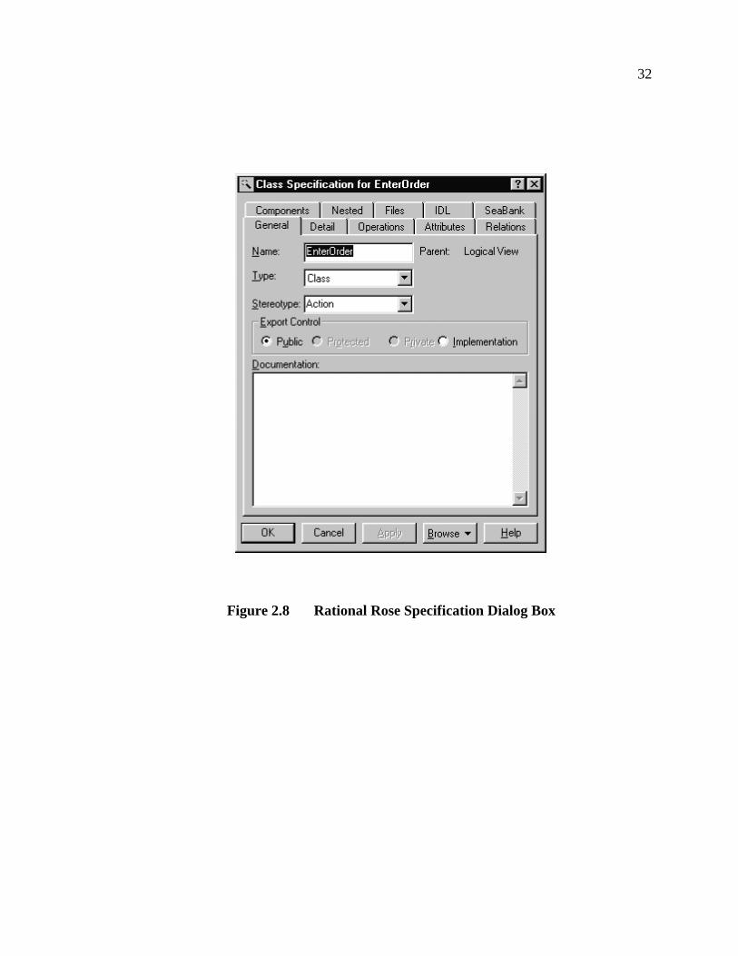
Rational Rose supports UML stereotypes and properties. Stereotypes can be added to a
model at any time, by simply typing in the name of the stereotype in the specification
dialog for a model element. This specification dialog presents all the information about
each model element. Figure 2.8 shows the specification dialog for a class.

31
Figure 2.7 Rational Rose Environment
32
Figure 2.8 Rational Rose Specification Dialog Box

33
Rose also supports stereotype configuration files. These files allow for a set of
stereotypes to be predefined when Rational Rose begins, or when an add-in is active. In
addition, the stereotype file allows a developer to provide files for an optional graphical
stereotype icon.
Stereotypes are important in Rational Rose and UML, as they allow designers to
model special types of classes in UML models. For example, stereotypes are used to
model distinguish Java interface classes, GUI form classes in Visual Basic, ActiveX
components, C++ header files and source files components, and so on. In addition,
developers can add new stereotypes to create new elements with specialized semantics
that represent the needs of software domain. SAGE uses stereotypes to distinguish
between the various component parts in a SeaBank component.
UML properties in Rose are managed differently than simple lists of key/value pairs.
Rose modularizes properties into related groups, allowing designers to quickly find and
change property values. Properties are first grouped by tool. Tools are often related to
languages or other generation tools, but this is not required. A tool appears as a separate
tab on the specification dialog box and is used to group related property sets in one place
in the dialog. For example, the C++ tool in Rose contains the C++ specific properties of
classes, packages, etc. In some cases, a tool is marked as language specific, and the tab on
the dialog box only appears if that element is assigned to that language.3 For example, the
C++ tool tab doesn’t appear until the element language is set to C++.
3 Setting the language is usually done by assigning the class to an UML component.

34
Each tool contains a default property set, and may contain other property sets. Each of
these property sets is divided into smaller sets associated with each UML element type.
For each element type, the property set is simply a collection of keys and values. Different
property sets may have the same keys as other sets but with different values, or a
completely different set of keys and values. The property values can have a boolean,
integer, string, or an enumerated type in Rational Rose. In UML values are only
represented as strings.
The designer can override the values of any property for each individual UML
element. In addition, the designer can create new property sets at design time by cloning
and changing the values of an existing set. The designer can change the values of a cloned
set, but can’t add or remove new property keys. Again, UML properties allow developers
to add new attributes to any UML element at design time.
In order to add new property keys to a set, the programming interface of Rose must be
used (BasicScript or external programs), or a property file must be created and loaded. A
property file contains a specification for tools, property sets and properties to be added to
a Rose model.
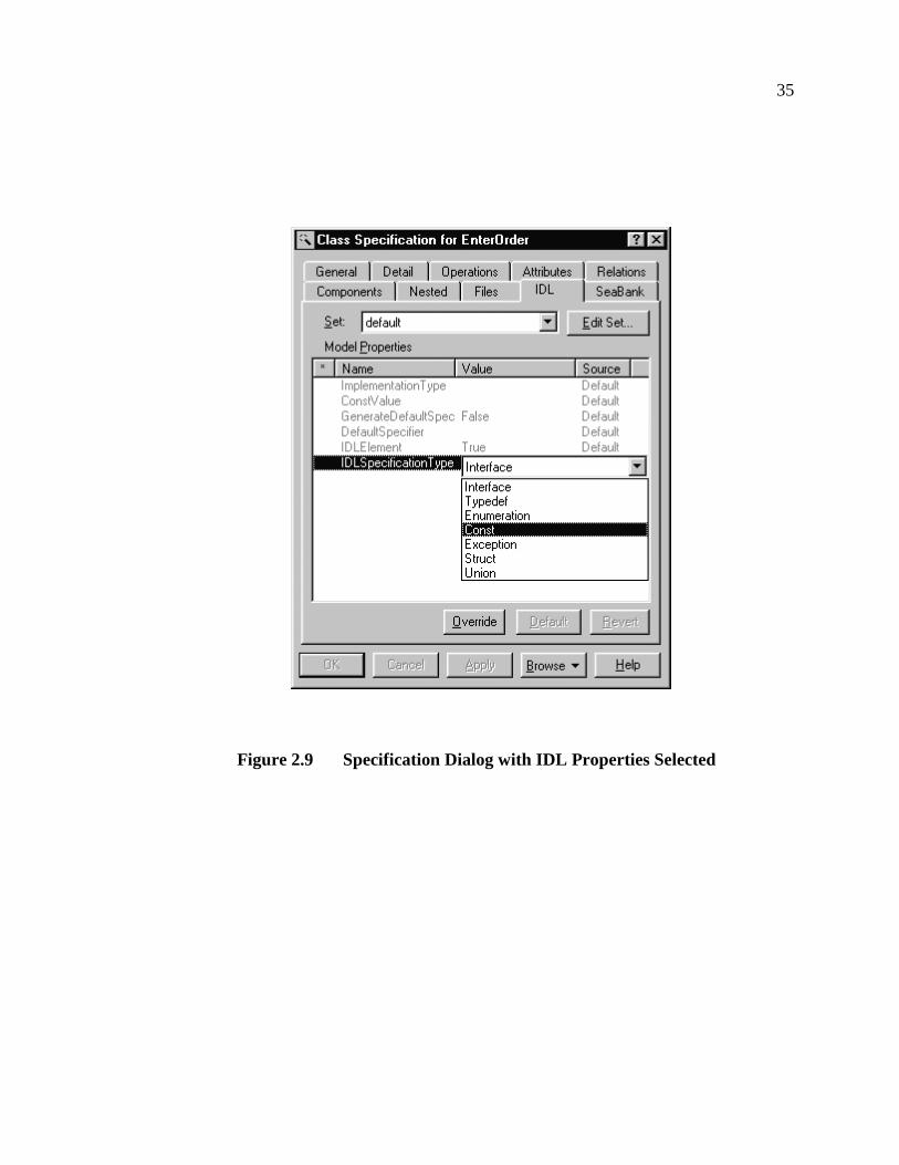
While UML properties in Rose is more complicated than a simple flat set of key/value
pairs, using properties in Rose is easy and logical, and many designers quickly adapt to
the Rose mechanism for properties. Figure 2.9 shows a specification dialog with the IDL
property tab selected.
The previous sections have presented the various technologies used to create SAGE.
The next chapter discusses SAGE in more detail.
35
Figure 2.9 Specification Dialog with IDL Properties Selected
36
CHAPTER 3
THE SAGE DEVELOPMENT TOOL
This chapter presents the SAGE tool, and how it is used and how it was designed.
SAGE is implemented as a Rose addin which allows developers to design SeaBank
applications with UML and Rational Rose and translate the models into the correct
SeaBank components.
Section 3.1 gives an overview of how SeaBank Task Model components are
developed and customized. Section 3.2 gives an overview of how to create a SeaBank
component model and generate SeaBank components with SAGE. Section 3.3 goes into
the details of how SAGE was designed. The UML model of the SAGE implementation is
presented and discussed. Also, this section presents the SeaBank generation metamodel.
This UML model gives a concise description of the various UML elements of the
SeaBank model and how the elements link together.
3.1 SeaBank Task Model Components
In the SeaBank framework, the component that has the most customization features is
the Task Model (TM) component. The TM component contains code that synchronizes a
GUI with the underlying data views and business objects and code that creates and
activates actions in the applications. Currently, the Business Object and Data Access
components in SeaBank have few customization features. As the framework matures, the
37
other components will be more customizable. As such, SAGE currently concentrates on
automating TM component generation.
In SeaBank, TM components have four types of component parts: TM, Action,
Viewer, and Business Object. Component parts implement part of the functionality that
the component provides. Each SeaBank TM component can contain zero or more
Business Object, Action, and Viewer parts, but they must have one and only one TM part.
The TM part is core of the component. This part is where the logic and code that
controls a task is placed. This is where the code that coordinates the interactions between
users and the other components in the system is located.
Action parts represent the ways in which the TM can update or add data in the
SeaBank software system. An example action would be a customer depositing a check in
a bank. The action part insures that the check can be deposited, updates the balance of the
account, and notifies the bank that the check needs to be processed.
Viewer parts filter and present complex data to the user of a Task Model in an easy to
use manner. Viewers also support automatic update and synchronization for viewed data.
An example viewer would present the account history for a specific bank account. If new
deposits, transfers or withdrawals were made, the viewer would show the new
transactions to the user.
Business Object (BO) parts represent the business rules and logic. These rules control
how the underlying business data is to be updated and kept consistent. An example BO
would be an object that enforces the rule: “Deposits over $10,000 must have approval
from the branch manager.” BOs are used to ensure that data in the enterprise is consistent
38
with a higher-level set of constraints and actions that can not be directly represented in
the database.
SeaBank components and component parts are implemented as Bassett frames. [13]
Frames simply are a set of text with embedded commands that controls the creation of
further text and the import and adaptation of other frames to create a customized text
product. In most cases, the text is code, and the frames are processed to create customized
software code. In SeaBank, frames are used to represent the generic components, and
component parts, and the frames are customized to produce application-specific
components and component parts.
3.1.1 Frames
Frames are code generation technology developed by Paul Basset to support reusable
software. At Netron, a company founded by Basset, frames are used to generate COBOL
programs for common business tasks. While the idea of frames is simple, the set of
commands provides a powerful means of creating customizable code. For SeaBank and
Coffee, frames are used to generate the C++ code for the various components.
Frames are similar to frames in Artificial Intelligence. In AI, a frame is a generic
structure that is adapted to yield a specific instance of the general idea. For example, a
fruit frame could yield an orange or banana, but not a cucumber. Likewise, Basset frames
generate specific implementations of a generic type of software. For example, Netron has
frames that automate the task of building COBOL database access and reporting code.
While frames are a powerful reuse mechanism, they are not easy to write and debug.
The nature of the commands for frames mean that a construction or compile time
39
program is being executed to create the code, and this generation process must be
debugged. Defects in the generated code must be traced back to see if they are introduced
in the generation process, and tracing defects to the generation process can be difficult. In
addition, frames require the developer to do the proper domain and reuse analysis to find
the proper set of software components to develop into frames. However, frames do
address the requirement for developing flexible software components that are adaptable to
specific requirements for applications.
The process of creating customized code by processing frames is controlled by a top-
level specification file, which is called the issue-answer file. This file contains a set of
frame commands, and more importantly, a set of questions and answers. The questions
represent the information that the frame processor must have to completely process the
other frames. The answers are the correct information required to produce customized
code. For SeaBank TM components, the issue-answer file contains the information about
the TM component and the information about the Action, Viewer and Business Object
parts the component uses. Figure 3.1 illustrates how this process is done manually.

40
Figure 3.1 SeaBank Manual Component Development Process
The next section goes into more details into how SeaBank components are manually
created by presenting a sample issue-answer file for a SeaBank Task Model component
that handles currency exchange orders.
3.1.2 Manual Generation of SeaBank Task Models
A SeaBank TM component issue-answer files has four sections. Each of these
sections contains information about specific parts of the TM component. Each action,
viewer, and business object part has a list of operations or parameters, which represent
how each part is used in the component.
The first section contains information on the TM component, and contains a list of the
Action, Viewer and BO parts used in the component. The following is the first section
from a sample SeaBank TM issue answer file:
Issue AnswerFile
FrameProcessor
SeaBank ApplicationComponents
SeaBankComponents
Developer
1: Creates
2: Controls
3: Customizes
4: Creates
41
.SET FN! ISSUE_ANSWER_CREATEORDER
.
.DEFAULT Parameters
.END-DEFAULT
.
.SET-COPY-LINES Issue_Answer_Text
What-Is-The-Name-Of-This-TaskModel?::CreateOrder
What-Are-The-Actions-For-This-TaskModel?::EnterOrder CheckOrderWhat-Are-The-Published-Action-Names?::ENTER_ORDER CHECK_ORDER
What-Are-The-Viewers-For-This-TaskModel?::OrderId OrderNameWhat-Are-The-Published-Viewer-Names?::ORDER_ID ORDER_NAMEWhat-Are-The-Types-Of-These-Viewers?::ItemViewer ItemViewerWhat-Are-The-Viewer-Notifier-Requirements?::TRUE FALSE
What-BusinessObjects-Might-Be-Used-By-This-TaskModel?::ForexOrder
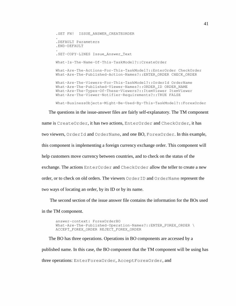
The questions in the issue-answer files are fairly self-explanatory. The TM component
name isCreateOrder , it has two actions,EnterOrder andCheckOrder , it has
two viewers,OrderId andOrderName , and one BO,ForexOrder . In this example,
this component is implementing a foreign currency exchange order. This component will
help customers move currency between countries, and to check on the status of the
exchange. The actionsEnterOrder andCheckOrder allow the teller to create a new
order, or to check on old orders. The viewersOrderID andOrderName represent the
two ways of locating an order, by its ID or by its name.
The second section of the issue answer file contains the information for the BOs used
in the TM component.
answer-context: ForexOrderBOWhat-Are-The-Published-Operation-Names?::ENTER_FOREX_ORDER \ACCEPT_FOREX_ORDER REJECT_FOREX_ORDER
The BO has three operations. Operations in BO components are accessed by a
published name. In this case, the BO component that the TM component will be using has
three operations:EnterForexOrder , AcceptForexOrder , and
42
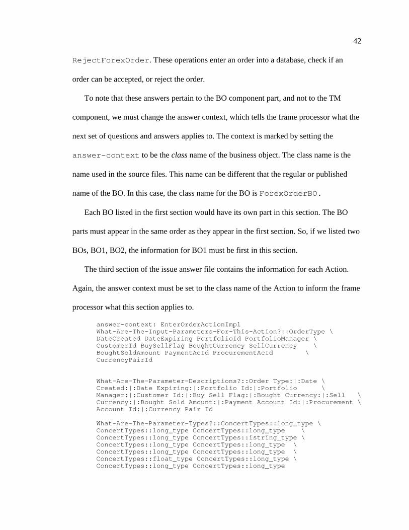
RejectForexOrder . These operations enter an order into a database, check if an
order can be accepted, or reject the order.
To note that these answers pertain to the BO component part, and not to the TM
component, we must change the answer context, which tells the frame processor what the
next set of questions and answers applies to. The context is marked by setting the
answer-context to be theclassname of the business object. The class name is the
name used in the source files. This name can be different that the regular or published
name of the BO. In this case, the class name for the BO isForexOrderBO.
Each BO listed in the first section would have its own part in this section. The BO
parts must appear in the same order as they appear in the first section. So, if we listed two
BOs, BO1, BO2, the information for BO1 must be first in this section.
The third section of the issue answer file contains the information for each Action.
Again, the answer context must be set to the class name of the Action to inform the frame
processor what this section applies to.
answer-context: EnterOrderActionImplWhat-Are-The-Input-Parameters-For-This-Action?::OrderType \DateCreated DateExpiring PortfolioId PortfolioManager \CustomerId BuySellFlag BoughtCurrency SellCurrency \BoughtSoldAmount PaymentAcId ProcurementAcId \CurrencyPairId
What-Are-The-Parameter-Descriptions?::Order Type:|:Date \Created:|:Date Expiring:|:Portfolio Id:|:Portfolio \Manager:|:Customer Id:|:Buy Sell Flag:|:Bought Currency:|:Sell \Currency:|:Bought Sold Amount:|:Payment Account Id:|:Procurement \Account Id:|:Currency Pair Id
What-Are-The-Parameter-Types?::ConcertTypes::long_type \ConcertTypes::long_type ConcertTypes::long_type \ConcertTypes::long_type ConcertTypes::istring_type \ConcertTypes::long_type ConcertTypes::long_type \ConcertTypes::long_type ConcertTypes::long_type \ConcertTypes::float_type ConcertTypes::long_type \ConcertTypes::long_type ConcertTypes::long_type

43
What-Are-The-Parameter-Qualifiers?::ConcertTypes::singleton_qual \ConcertTypes::singleton_qual ConcertTypes::singleton_qual \ConcertTypes::singleton_qual ConcertTypes::singleton_qual \ConcertTypes::singleton_qual ConcertTypes::singleton_qual \ConcertTypes::singleton_qual ConcertTypes::singleton_qual \ConcertTypes::singleton_qual ConcertTypes::singleton_qual \ConcertTypes::singleton_qual ConcertTypes::singleton_qual
Each action contains a set of parameters. These parameters are the information needed
to complete the action. Each parameter has a name, a description, a type and a qualifier
type, which are all used by the SeaBank framework to describe certain information. For
theEnterOrder action we have: the order type, the date it is created and expires, the
Portfolio Id of the customer, the manager of this profolio, the customer’s ID, if the action
is a buy or sell action, and other information.
Since we have two Actions, we would have another part that lists the parameters for
theCheckOrder action. We do not show the second part of issue-answer file for the
CheckOrder action. Like the section for BOs, the actions must appear in the same
order as it appears in the first section.
The fourth section of the issue answer file contains the information for each Viewer.
The answer context is set to the class name of the Viewer, and the information for each
Viewer appears in a set of questions for that Viewer.
answer-context: OrderIdViewer
What-Items-Will-Be-Viewed-Through-This-Viewer?::OrderIdWhat-Are-The-Item-Descriptions?::Order Id:|:What-Are-The-Item-Types?::ConcertTypes::long_typeWhat-Are-The-Item-Qualifiers?::ConcertTypes::singleton_qual
Just like Actions, Viewers have a set of parameters that represent the data being
viewed. These parameters also have a name, a description, a type and a qualifier type. In
this case, theOrderId Viewer only has one parameter, which is the ID number of the
order. Again, we would have another part for the information for theOrderName
44
Viewer (not shown here), and again, the order of the viewers must be the same as the
order in the first section.
It should now be clear that understanding and using the SeaBank TM issue answer
files is not simple. For a set of 10 or more TM components, the issue answer files can
become large and hard to maintain. In addition, if the TM components share Actions,
BOs or Viewers parts, the corresponding sections must be cut and pasted into the issue
answer file for each component. If a part is changed in one issue answer file, all the
changes must be made to all the files that use that part. This makes it difficult to maintain
files.
SAGE makes the task of maintain and generating the issue-answer files much easier,
by creating them from UML models. We discuss how to use SAGE in the next section.
3.2 Generating SeaBank Task Models with SAGE
SAGE simplifies the development of SeaBank Task Model(TM) components by
allowing the developer to create a UML model of the TM components, including the
various Action, Viewer and Business Object parts the TM components use. The
developer then selects the TM component(s) that they wish to generate issue-answer files
for, and the tool examines the UML model, checks to see if all the required parts are
assigned to the component, and then generates the issue answer file from the model.
SAGE can rapidly generate SeaBank TM components from a model and is excellent
for managing large sets of SeaBank components. An additional advantage of SAGE is
that Rational Rose can be used to model other parts of the applications. For example,
Rose can be used to model databases, C++, Java, and Visual Basic, and CORBA IDL

45
classes, and these classes can be used in the application. The developer is not required to
use a separate CASE tool for modeling or creating the other parts of an application.
Figure 3.2 shows the process of generating SeaBank components with SAGE. Instead
of developers creating the issue answer files by hand, the developer creates a model with
Rational Rose, and SAGE translates the model into the appropriate issue-answer files.
Figure 3.2 SeaBank Component Generation Process with SAGE
The models of the SeaBank components and component parts are easy to create and
change and sharing parts between components is very easy. The next section discusses
how to create SeaBank component models and how to generate new components with
SAGE.
RationalRose
SeaBankDesign Model
SAGE
2: Translates
Issue AnswerFile
3: Creates
FrameProcessor
SeaBankComponents
5: Customizes
SeaBank ApplicationComponents
6: Creates
1: Developer Creates
4: Controls

46
3.2.1 Creating SeaBank Models and Generating Components
Users of SAGE must be familiar with the basic workings of Rational Rose before they
can use SAGE. Developers must understand the basics of adding classes and components,
organizing models, assigning classes to components, and setting class stereotypes and
property values. Future versions of SAGE may have wizards to simplify this process.
Readers unfamiliar with Rational Rose may wish to consult [11] as a reference for using
Rational Rose.
In this example, we will show how to generate the TM component and issue-answer
file presented in section 3.1. This TM component allows customers to exchange
currencies and track the status of the orders.
The first step in generating SeaBank TM components is to create the component
model. The SeaBank components can be placed on any component diagram, but it is
simpler if all the SeaBank model components appear on one component diagram. To
create the TM component, we first add a component namedCreateOrder to the main
component.
We then set the component language to be SeaBank. This notifies SAGE and other
designers that the component represents a SeaBank component. We open the
specification dialog for the component and select SeaBank for the component language,
and we apply the changes. We apply the changes so that the SeaBank stereotypes now
appear in the stereotype list. Since, this is a TM component, we select the TaskModel
stereotype is chosen. Figure 3.3 shows a screen shot of Rose during this step. These steps
are repeated for each SeaBank TM component used.
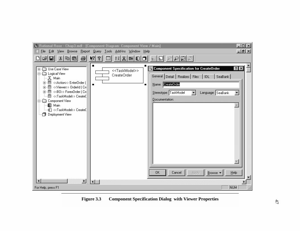
47Figure 3.3 Component Specification Dialog with Viewer Properties
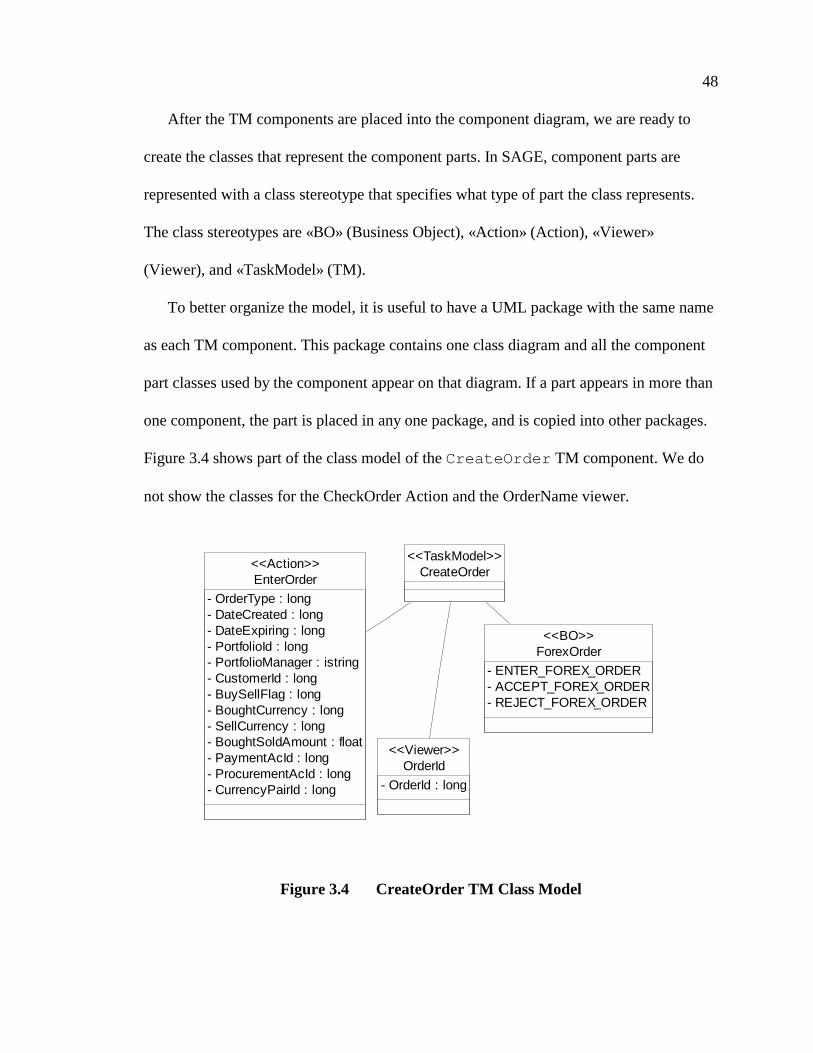
48
After the TM components are placed into the component diagram, we are ready to
create the classes that represent the component parts. In SAGE, component parts are
represented with a class stereotype that specifies what type of part the class represents.
The class stereotypes are «BO» (Business Object), «Action» (Action), «Viewer»
(Viewer), and «TaskModel» (TM).
To better organize the model, it is useful to have a UML package with the same name
as each TM component. This package contains one class diagram and all the component
part classes used by the component appear on that diagram. If a part appears in more than
one component, the part is placed in any one package, and is copied into other packages.
Figure 3.4 shows part of the class model of theCreateOrder TM component. We do
not show the classes for the CheckOrder Action and the OrderName viewer.
Figure 3.4 CreateOrder TM Class Model
ForexOrder
- ENTER_FOREX_ORDER- ACCEPT_FOREX_ORDER- REJECT_FOREX_ORDER
<<BO>>
EnterOrder
- OrderType : long- DateCreated : long- DateExpiring : long- PortfolioId : long- PortfolioManager : istring- CustomerId : long- BuySellFlag : long- BoughtCurrency : long- SellCurrency : long- BoughtSoldAmount : float- PaymentAcId : long- ProcurementAcId : long- CurrencyPairId : long
<<Action>>
OrderId
- OrderId : long
<<Viewer>>
CreateOrder<<TaskModel>>

49
For each part of the TM component, a class is created and the name set to the regular
name of the part, but the stereotypes for the class part are not available in the stereotype
list. This is because these classes have not been assigned to a SeaBank component. To
assign the classes to the SeaBank language, select the SeaBank component, open the
specification dialog, and assign the classes to the component by selecting the Realizes
tab. Apply the changes, and the proper stereotypes should then appear in the stereotype
list for the classes.
If developers do not want to assign the parts to any component at this stage, but still
want to use the stereotypes for the SeaBank parts, they can type the name of the
stereotype in the specification dialog, even though the stereotype is not yet available as a
predefined stereotype. However, classes must be assigned to a TM component or it will
not be used as a part of the TM component.
The TM part does not have any parameters, so we make a class with the stereotype
«Task Model» with no attributes or operations. The class name is name of the TM part. It
is important to note that the UML class name isnot the SeaBank descriptive name or
answer context. These are stored as properties of the class.
In the class specification, the SeaBank properties appear under the SeaBank tab. The
properties have four sets of property values. For the TM part, use the default set of
properties and manually override values if needed. If the class has not been assigned to a
SeaBank component, the properties are not available and the tab does not appear.
For Action or Viewer parts, we make a class with the stereotype «Action» or
«Viewer» respectively. Like the TM part, the descriptive name and answer context as
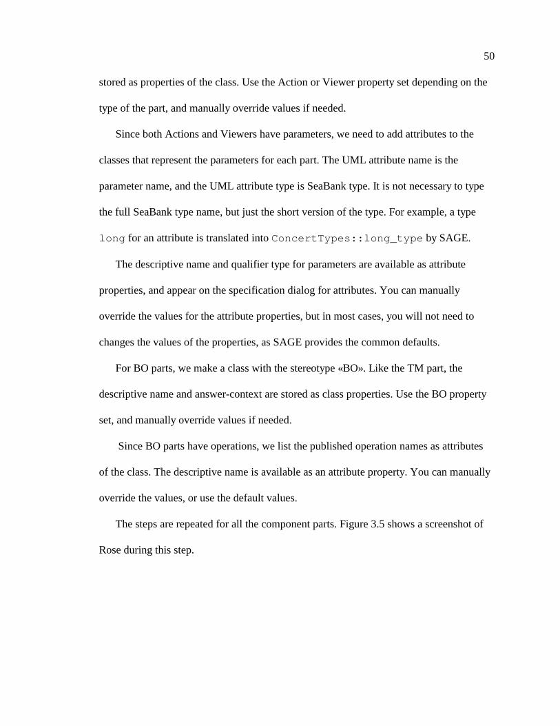
50
stored as properties of the class. Use the Action or Viewer property set depending on the
type of the part, and manually override values if needed.
Since both Actions and Viewers have parameters, we need to add attributes to the
classes that represent the parameters for each part. The UML attribute name is the
parameter name, and the UML attribute type is SeaBank type. It is not necessary to type
the full SeaBank type name, but just the short version of the type. For example, a type
long for an attribute is translated intoConcertTypes::long_type by SAGE.
The descriptive name and qualifier type for parameters are available as attribute
properties, and appear on the specification dialog for attributes. You can manually
override the values for the attribute properties, but in most cases, you will not need to
changes the values of the properties, as SAGE provides the common defaults.
For BO parts, we make a class with the stereotype «BO». Like the TM part, the
descriptive name and answer-context are stored as class properties. Use the BO property
set, and manually override values if needed.
Since BO parts have operations, we list the published operation names as attributes
of the class. The descriptive name is available as an attribute property. You can manually
override the values, or use the default values.
The steps are repeated for all the component parts. Figure 3.5 shows a screenshot of
Rose during this step.
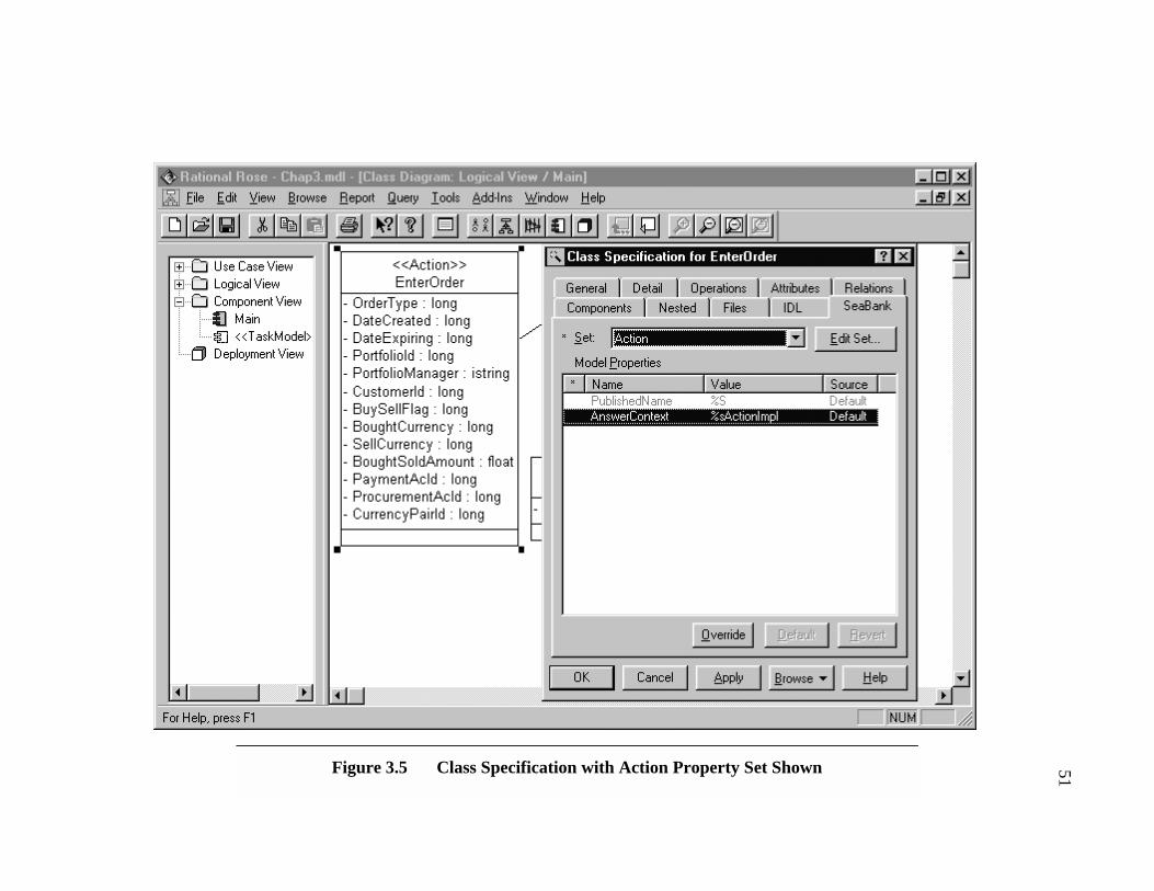
51Figure 3.5 Class Specification with Action Property Set Shown

52
Setting the property values for every single class and attribute would be tedious and
somewhat time-consuming, especially since in most cases the values are just simple
transformations of the attribute name. For example, the parameterOrderId has a
published nameORDER_ID, and description Order Id. The answer context for an Action
partEnterOrder is EnterOrderActionImpl . The default property values in the
SAGE tool represent these commonly used values by supporting transformation directives
in properties. This means that in the default case, the developer only has to select the
correct property value set to get the correct values.
SAGE supports three transformation directives in property values. These directives
are like directives in a C printf statement. The%sdirective in a property value replaces
the directive with the name of the UML element. For example, the class property with the
value%sActionImpl in a class namedCreateOrder would be translated as
CreateOrderActionImpl . The%Sdirective in a property value replaces the
directive with the all caps version of the element name. Each capital letter after the first
character is followed by an underscore, and all the characters are transformed to
uppercase. For example, the property value%S_BAZfor an attribute namedFooBar
would be translated asFOO_BAR_BAZ. The%ndirective in a property value replaces the
directive with the whitespace version of the element name. Each capital letter after the
first character is followed by a space. For example, the property value%n for an attribute
namedThisIsASpace would be translated toThis Is A Space .
53
The property sets for SeaBank classes have the default values that are common for
each type of SeaBank part. For example, theAnswerContext property has the default
value%sViewer in the Viewer property set.
After the classes are created and assigned to the components and the property values
are all set, the issue answer files can be created. Each component must have one and only
one TM class assigned to it, but can have zero or more Action, Viewer or Business Object
classes assigned to it. If a component has more than one TM class, an error is flagged
Each SeaBank TM component has a property that specifies the directory where the
issue answer file should be placed. The default is the current working directory, but this
can be unpredictable. It is recommended that the user override the default value of this
property to the directory in which the files should be placed.
To generate code, the user selects one or more SeaBank components in the model,
and chose theGenerate Code option. The issue answer files will be created, and any
errors during generation will be reported in the Rose log window. In this example, SAGE
makes an issue answer file that is semantically identical to the file we presented in
Section 3.1.
The order in which SeaBank model elements are created is not important. The order
presented here is suggested as a good way to create SeaBank models, but developers are
free to choose any method they prefer, as long as the model must be consistent. This
requires all the stereotypes and properties to be set correctly, and each TM component
must have one and only one TM class assigned to it.
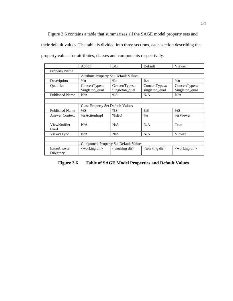
54
Figure 3.6 contains a table that summarizes all the SAGE model property sets and
their default values. The table is divided into three sections, each section describing the
property values for attributes, classes and components respectively.
Action BO Default ViewerProperty Name
Attribute Property Set Default ValuesDescription %n %n %n %nQualifier ConcertTypes::
Singleton_qualConcertTypes::Singleton_qual
ConcertTypes::singleton_qual
ConcertTypes::Singleton_qual
Published Name N/A %S N/A N/A
Class Property Set Default ValuesPublished Name %S %S %S %SAnswer Context %sActionImpl %sBO %s %sViewer
ViewNotifierUsed
N/A N/A N/A True
ViewerType N/A N/A N/A Viewer
Component Property Set Default ValuesIssueAnswerDirectory
<working dir> <working dir> <working dir> <working dir>
Figure 3.6 Table of SAGE Model Properties and Default Values
55
3.3 SAGE Design and Implementation
SAGE was designed with rapid prototyping in mind. The tool was not meant to be a
production quality tool in its first inception. Instead it was a tool that could be quickly
created to evaluate the feasibility of UML and Rational Rose as tools for generating
SeaBank components, and for evaluating the support for and effectiveness of component
generation in SeaBank.
In order to support rapid prototyping of SAGE, Visual Basic (VB) was chosen as the
implementation language for SAGE. Visual Basic is a programming language and IDE
environment created by Microsoft to support the rapid development of GUI applications
in the Windows environment. Before Visual Basic, Windows development involved
creating complicated and difficult to understand C or C++ code. [43-45]
While VB is still a very powerful tool for GUI programming, it has been extended to
be a complete language for prototyping and developing all types of Windows
applications. VB uses COM as its native object model, and using COM objects and
creating new COM objects in VB is very simple, compared to other Visual Studio tools
like C++ and J++. [42] By supporting COM, Visual Basic also supports object oriented
programming concepts like classes and interface-based polymorphism. Since COM
objects are easy to access and create in VB, VB is ideal for creating SAGE. The Rose
Extensibility Interface is a set of COM objects, and Rose Addins are COM objects as
well.
Section 3.3.1 presents the SeaBank Generation Metamodel. This UML model
concisely presents how the UML elements, stereotypes and properties are used to model

56
SeaBank components. This metamodel was used as a reference in creating the design of
SAGE. Section 3.3.2 discusses how SAGE was designed and implemented by using
UML, Rational Rose and VB.
3.3.1 The SeaBank Generation Metamodel
To help concisely capture how the SAGE tool would interact with Rose, a metamodel
of the SeaBank component models was developed. This model shows the format and
information that a valid SeaBank component model in UML contains. Like the UML
metamodel is a powerful tool for reasoning about UML, the SeaBank generation
metamodel is a useful tool for reasoning about SAGE. We refer to the metamodel as a
generation metamodel, since it only contains information about how to generate SeaBank
TM components, and does not contain all the information about SeaBank TM
components.
We first present the class diagram of the metamodel in Figure 3.7. There are four
classes each representing the component parts in SeaBank. The TaskModel has a
constraint based associated with the Action, Viewer, and BO classes. These constraints
restrict the classes to only having a certain stereotype.

57
Figure 3.7 SeaBank Generation Metamodel
Action
+ PublishedName : Class::Property::String = "%S"+ ActionName : Class::Name+ InputParameters : list<Class::Attribute>+ ParameterDescription : Attribute::Property::String+ ParameterQualifer : Attribute::Property::String+ AnswerContext : Class::Property::String = "%sActionImpl"
Viewer
+ ViewerType : Class::Type+ ViewerName : Class::Name+ UsesNotifer : Class::Property::Boolean = true+ ItemList : list<Class::Attribute>+ ItemType : Attribute::Property::String = "ListViewer"+ ItemQualifer : Attribute::Property::String+ AnswerContext : Class::Property::String = "%sViewer"+ PublishedName : Class::Property::String = "%S"
BusinessObject
+ PublishedOperationNames : list<Class::Attribute>+ AnswerContext : Attribute::Property::String = "%sBO"
TaskModel
+ TaskModelName : Class::Name
0..*+ActionList
0..*
{ActionList->forAll(a | a.stereotype.name = 'Action')}
+theTaskModel
0..*+ViewerList 0..*{ViewerList->forAll(v | v.stereotype.name='Viewer')}
+theTaskModel
0..*+BOList 0..* {BOList->forAll( b | b.stereotype.name='BO')}
+theTaskModel
self.stereotype= 'TaskModel'

58
The constraints are specified in OCL (Object Constraint Language). OCL is a part of
the UML standard and is used as the language for formally specifying constraints on
model elements. The OCL is used extensively as part of the UML metamodel to formally
describe the constraints that all UML models must follow. While we can not discuss the
OCL in detail, we give a brief explanation of the constraints in the SeaBank metamodel.
The OCL is presented in detail in [46].
Each element in the model can be referenced in OCL by its name, or by the keyword
self , which refers to the element the constraint is attached to. Each element in OCL has
a set of attributes that are associated with the element. The only attribute used in the
SAGE generation metamodel is the stereotype attribute. In the SeaBank metamodel, the
constraints are attached to the associations between the TaskModel class and the other
classes.
Each of the constraints on the associations states that all of the objects associated with
a TM must have a certain stereotype. The constraint: {ViewerList-> forall(v |
v.stereotype = ‘Viewer’)} states that every class element in the ViewerList
role of the association must have a stereotype «Viewer». So, the constraints on the
associations state that every Action associated with a TaskModel has a stereotype
«Action», that every Viewer associated with a TaskModel has a stereotype «Viewer», and
that every Business Object associated with a TaskModel has a stereotype «BO». The
constraint in the note in the class diagram states that a TM has a stereotype «TaskModel».
Each class in the metamodel has a set of attributes. These attributes specify all of the
generation information, and the type of the attribute notes where the information is
59
located in the model element. For example, the classViewer has the following
attributes:
ViewerName : Class::NameViewerType : Class::TypeItemNames : list<Class::Attribute::Name>ItemTypes : list<Class::Attribute::Type>ItemQualifer : Attribute::Property::Boolean = TrueAnswerContext : Class::Property::String = “%sViewer”PublishedName : Class::Property::String = “%S”
The ViewerName and ViewerType of a viewer are the class name and type of the
model element. The ItemNames and ItemTypes are the list class attributes names and
types, respectively. The ItemQualifier is a boolean attribute property with a default value
of true . The AnswerContext is a string class property with the default value of
“%sViewer” and the PublishedName is a string class property with the default value of
“%S” . Each property name is the same as the name of the attribute in the metamodel.
It is important to note that this notation is not a formal convention, but is simply an
informal way of specifying which part of the model element will contain the information
needed by the SAGE tool.
The second part of the metamodel is a component named TaskModel with all the
metamodel classes assigned to it. The documentation of this component informally states
that the classes in a SeaBank model must be assigned to a component with language
SeaBank in order for code generation to take place.
While the SeaBank metamodel is not a completely formal description of SeaBank
models in SAGE, it is a powerful and concise description of the information needed to
create SeaBank components, and specific where the information is located in a SeaBank
component model in SAGE. This metamodel was used to design SAGE.
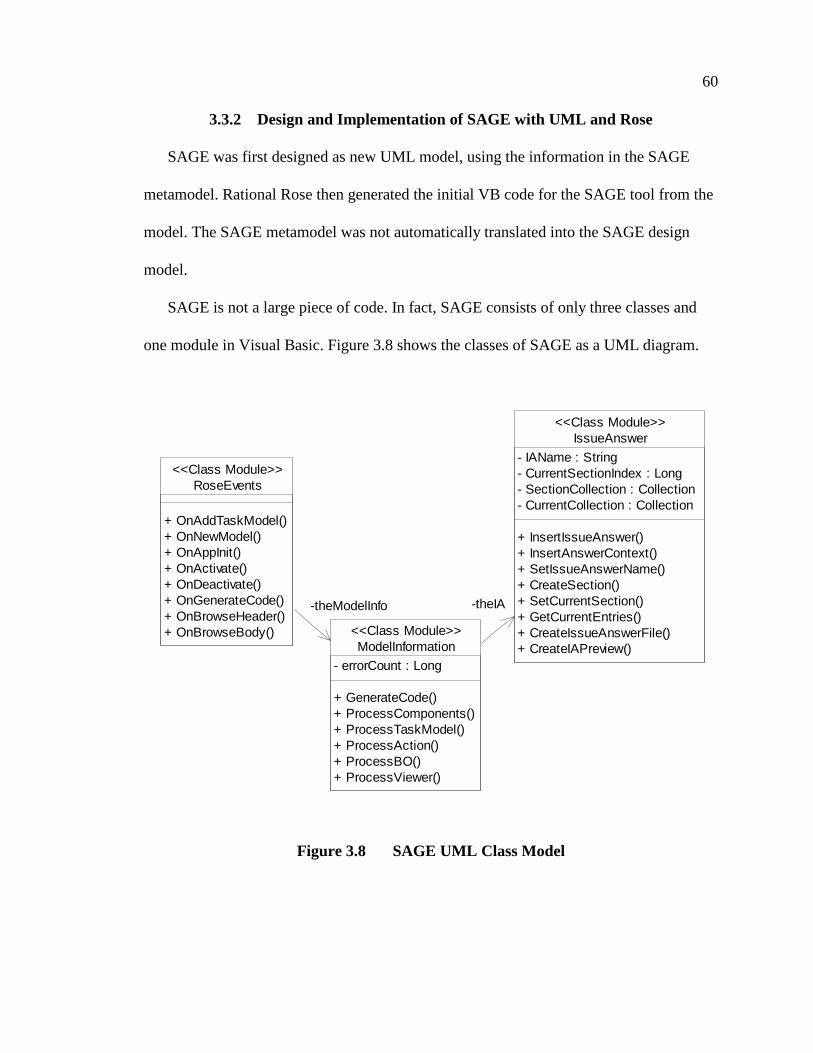
60
3.3.2 Design and Implementation of SAGE with UML and Rose
SAGE was first designed as new UML model, using the information in the SAGE
metamodel. Rational Rose then generated the initial VB code for the SAGE tool from the
model. The SAGE metamodel was not automatically translated into the SAGE design
model.
SAGE is not a large piece of code. In fact, SAGE consists of only three classes and
one module in Visual Basic. Figure 3.8 shows the classes of SAGE as a UML diagram.
Figure 3.8 SAGE UML Class Model
RoseEvents
+ OnAddTaskModel()+ OnNewModel()+ OnAppInit()+ OnActivate()+ OnDeactivate()+ OnGenerateCode()+ OnBrowseHeader()+ OnBrowseBody()
<<Class Module>>
IssueAnswer
- IAName : String- CurrentSectionIndex : Long- SectionCollection : Collection- CurrentCollection : Collection
+ InsertIssueAnswer()+ InsertAnswerContext()+ SetIssueAnswerName()+ CreateSection()+ SetCurrentSection()+ GetCurrentEntries()+ CreateIssueAnswerFile()+ CreateIAPreview()
<<Class Module>>
ModelInformation
- errorCount : Long
+ GenerateCode()+ ProcessComponents()+ ProcessTaskModel()+ ProcessAction()+ ProcessBO()+ ProcessViewer()
<<Class Module>>
-theModelInfo -theIA

61
TheRoseEvents class is the external COM interface of the SAGE tool. This
interface matches the interface that all Rose addins must support. Rose fires a number of
events based on what happens in the tool. The following is a brief list of the events and
when they are fired.
• OnAppInit : This event is fired when Rose is started.
• OnActivate : This event is fired when the addin is activated in the Addin
Manager
• OnDeactivate : This event is fired when the addin is deactivated in the
Addin Manager
• OnGenerateCode : This event is fired when the Generate Code menu
option is selected.
• OnBrowseBody : This event is fired when the Browse Body menu option is
selected.
• OnBrowseHeader : This event is fired when the Browse Header menu
option is selected.
TheIssueAnswerFile class is used to create an issue-answer file. Since the issue
answer file must be in a certain order, and information from the model comes in a random
order, this class must store the information in the appropriate sequence. The
IssueAnswerFile class contains an ordered collection of sections in the file, with
each section containing an ordered collection of text, which is the collection of question-
answers in the issue-answer file. Clients of this class can create any number of sections,
change the current section, and insert a question-answer into any position in the current

62
section. This class allows SAGE to easily put all the issue answer file information in the
proper order regardless of the order it is received from the model.
TheModelInformation class is the core of the SAGE tool. This class navigates
through the model by using the Rose Extensibility Interface and extracts the information
about the SeaBank components from the model, and creates the issue answer files. Figure
3.9 shows how code generation proceeds in SAGE as UML sequence diagram.
In addition to the three classes, the SAGE tool contains one VB module that contains
utilities for finding and translating properties in the SeaBank model. The function
ProcessProperty in the module takes a UML element object, the tool and property
name, and returns the processed value of the property. This function uses other functions
to search for property processing directives (%s, %S, %n) and replaces them with the
appropriate text.

63
Figure 3.9 UML Sequence Diagram for Code Generation
: Rational Rose
: RoseEvents
: ModelInformation
: IssueAnswer : IssueAnswer
File
OnGenerateCode(Object)
GenerateCode(RoseApplication)
ProcessComponents(RoseModuleCollection)
Should be calledonly once
ProcessTaskModel(RoseClass)
InsertIssueAnswer(String, String)
CreateSection(Long, String)
Called foreach section
ProcessAction(RoseClass)
Called for eachAction
ProcessBO(RoseClass)
Called for eachBO
InsertIssueAnswer(String, String)
InsertIssueAnswer(String, String)
ProcessViewer(RoseClass)
Called for eachViewer
InsertIssueAnswer(String, String)
CreateIssueAnswerFile(String)File Created
64
3.3.2.1 SAGE Implementation Effort and Costs
SAGE did not take long to implement after the first UML designs were created. The
implementation took about four to six person-weeks of total effort. In addition, four
person-weeks were taken to create a prototype model browser in Visual Basic. This
browser project was to use and study the Rose Extensibility Interface in detail before
proceeding with the SAGE development effort. Also, one person-month was spent
learning the Rose Extensibility Interface before any prototyping began.
It is important to note that learning how to use Rational Rose and the REI (Rose
Extensibility Interface) does requires a significant amount of developer effort. It is
reasonable to expect developers to each take 6 to 12 person-months before mastering
Rational Rose and the REI. Developers with previous experience with Rose and OLE
programming may take only 3 to 6 person months. This learning curve could be further
accelerated with Rose and REI training courses, or if developers have previous
experience with Rational Rose.
SAGE is not a large piece of code. In fact, it is only about 600 SLOC (Source Lines of
Code) of Visual Basic. The fact that the code is not very large shows that the features of
Rational Rose and SeaBank were reused as much as possible. For example, the SAGE
tool does not contain its own frame processor, but instead has developers use the
command-line frame processor that comes with the SeaBank framework. Also, we use as
many features as possible in Rational Rose to store and manage SeaBank information.
In order to test that SAGE had reached a proper level of maturity, it was decided that
SAGE must reproduce three issue answer files that were created as part of a SeaBank
demo at HP Labs. The issue-answer files must be created solely from a SeaBank
65
component model in Rose, and the files must be semantically equivalent. The tool passed
these tests three person-weeks into development.
3.4 Summary
The process of designing and implementation of SAGE shows how flexible and
powerful Rational Rose and the UML are for development. UML was used to create a
SeaBank generation metamodel and was used to model the SAGE code. The actual size
of the SAGE tool is rather small, and this points out that the implementation effort for
making an extension of Rose for application generation can be very reasonable in terms
of code size and developer effort. However, learning to use and develop with Rational
Rose requires significant effort, and impacts the costs of tool development. In addition,
the powerful notion of frames and code generation with issue-answer files in SeaBank
further simplified the task of creating the SAGE tool.
It is certain that similar tool projects may not be as easily undertaken as the SAGE
project was. The scope, maturity and complexity of the framework or components can
have a great impact on how difficult it is to create a generation tool with Rose. However,
tool development may have a positive impact on developer productivity, and the costs of
developments may be a worthwhile investment.
In the next chapter, we evaluate the effectiveness of Rational Rose, UML and
SeaBank for supporting rapid component-based application development tools. Each
element had a number of advantages and disadvantages that contributed to the scope and
quality of SAGE.
CHAPTER 4
PROJECT EVALUATION
This chapter presents the evaluation of the SAGE development effort. While SAGE is
not a production quality tool, the development of the tool highlights some of the
advantages and disadvantages of UML, Rational Rose and SeaBank for component-based
and framework-based application development and development tools.
We give some insights into how future components, frameworks and tools need to be
developed to be as effective as possible. We show that while current technologies are
very useful, there are ways the technologies need to improve to better support application
development.
Section 4.1 evaluates the features of UML for application generation and component
modeling. Section 4.2 evaluates Rational Rose and how effectively it supports the UML
and extensibility for developing third party tools. Section 4.3 evaluates the SeaBank and
Coffee frameworks, and how well they support application and component development,
component customization, and how well they integrate with SAGE and other generation
tools. Section 4.4 compares SAGE with the previous SeaBank generation tool, Composer.

67
4.1 Evaluation of UML
UML is a powerful standard for software modeling and development. The UML
models a broad spectrum of software development tasks, from requirements to class
structure. Models are an important aid in designing, documenting, debugging and
maintaining software. However, no modeling language can model every aspect of
software. Obviously, modeling improves the quality and effectiveness of coding and
software implementation, but modeling languages can not replace coding and
implementation languages.
With the advent of OO programming, modeling notations and the UML are playing a
more important role in software development and documentation. UML captures many
important semantics aspects of OO software design and implementation. Instead of vague
textual or pseudo-code descriptions of a software design, the UML organizes and
formalizes the design.
UML can also lend organization to software documentation. Additional
documentation can contain references to or show diagrams that compactly illustrates a
particular aspect of the software design. The documentation of a software design can
match the UML hierarchy of packages, allowing developers to quickly navigate both
model and documentation to find information about a particular element of the software.
68
4.1.1 UML Advantages
UML was obviously designed with OO and component programming in mind.
Components and component interfaces are native to UML, and components in UML
match many aspects of component technologies like COM and CORBA. UML also
explicitly supports a special notation to connect classes with component interfaces.
UML is a powerful tool for modeling class hierarchies. Since many component
software projects use classes to implement components or frameworks, the class
modeling aspects are essential to component-based programming. Sequence and
collaboration diagrams can show how components interact, and show proper usage
scenarios for components. State diagrams can concisely model a component’s internal
state and how it changes after receiving various messages.
However, the SAGE tool does not use many of the UML features to support SeaBank
application development. The parts of a SeaBank component are modeled as stereotyped
classes, with the attributes containing the information for the issue-answer files. A
component is used to group together the SeaBank classes into a single TM component.
The SAGE tool looks at all the classes assigned to the component, checks if one and only
one TM class was assigned to the component, and creates the issue answer file. So,
naturally one may ask if UML is too complicated for a simple tool like SAGE.
For the current tool, the full power of UML is not needed. However, if the tool is used
in the larger context of SeaBank development, it is clear that the UML is useful for
modeling the entire software project, and not just the SeaBank components. A more
powerful tool for SeaBank could, for example, allow classes to be tied to any SeaBank
parts and components and automatically generate all of the glue code between simple

69
C++ or Java classes and actual components. Data Access components in SeaBank could
be directly tied to a model of a database, and code could be generated that automatically
accessed and queried the database. Sequence diagrams could be used to help
automatically generate code for complex interactions in the SeaBank application. State
and Activity diagrams could be used to model and create code for workflows in the
application.
Clearly, having SAGE use the full power of UML is an advantage, because UML
enables many other software development activities, and the tool could be extended to
support many more SeaBank development activities than it currently supports. Also, the
UML notions of a class and component correspond well with the notions of a part and
component in SeaBank. Finally, the generic software development features that UML
supports make it useful for any software project.
The advantages that UML provided SAGE are the easy mapping of SeaBank parts and
components onto UML classes and components, and the ability to model many other
aspects of a SeaBank application.
4.1.2 UML Disadvantages
While UML is a powerful modeling language, it is still a very new standard. Wide-
scale support of the UML is still building, and many important parts of the UML and
related standards are not completely supported or developed. In addition, the exact
semantics of UML are still not well understood and in some cases are quite complicated.
For example, no tools that fully implement the standard for exchanging UML models
exist. Ad-hoc tools like the Microsoft Repository allows offers some tool interoperability,
70
but it is not complete. For example, the Repository does not preserve the layout of a UML
model. The CDIF standard addresses the exchange of graphical models, but no
implementations of the standard exist.
The Meta-Object Facility (MOF) standard for UML models is a standard that supports
the interchange of models and metamodels. The standard is presented as a large set of
CORBA IDL interfaces. These interfaces provide access to all the core information that a
model contains. Unisys provides a repository product, UREP, which is based on the MOF
standard. However, it is not clear how well UREP and MOF support the transfer of model
properties and stereotypes, and this is crucial for tools like SAGE.
To really use the UML, tools are needed. Most CASE tools are expensive, and this
can be a significant cost to smaller organizations. In addition, these tools have no
redistributable parts, so if a software company wishes to create a third party tool that
supports the UML, they must make their own UML drawing or CASE tool, or resell the
CASE tool as part of the software.
This means that software vendors may have to contract with other parties for UML
based applications, and the lack of interoperability solutions may tie developers to
supporting only one CASE tool or UML product. If the tool changes or new tools need to
be supported, the third party tools may have to change significantly. Using repository
technology could alleviate some of these problems.
Also, the UML is missing some core features that would be useful in modeling
components. For example, the UML has no notion of exceptions in the core of the UML,
and the UML has limited support for modeling concurrency aspects of software. For
example, no features exist to model threads in UML, and tie them to classes or
71
components. UML also has no concept of rules, which are commonly used in many
systems.
Of course, the extensibility features of UML could allow these notions to be added to
UML. It is difficult to determine what features must be supported in the UML core
standard, and what features that are best supported as standard extensions to the UML
core, and those features which are too implementation-dependent to be standards. Also,
since the UML semantics and metamodel are relatively new and not yet widely
understood, it is difficult to understand exactly how various extensions should be
implemented in relation to the UML. For example, in the SeaBank generation metamodel,
an ad-hoc type scheme was used to concisely identify attributes as being a specific UML
element, since no standard typing scheme exists. It is not entirely clear how information
from the UML metamodel is to be used and presented in a UML model.
One feature that would be useful that is not supported by the UML is typed properties.
Properties in UML are merely key-value pairs, and the key and values have no type
associated with them. Rational Rose extends the notion of a UML property to include
types like string, boolean, integer, etc. While UML may not need to support a complete
type system for properties, it would be a useful extension if UML stored type names for
the keys and values of properties. These type names could serve as hints as to how the
data in the properties is to be interpreted. UML currently states that all keys and values
are just strings.
Another feature that would be useful but is not supported by the UML is variation
points for UML elements. Variation points were first used as part of the Reuse Business
72
framework notation in [14]. Variation points for an UML element represents the specific
points or places that a UML element can be customized.
For example, if a component can optionally support object transactions, this could be
modeled as a variation point on the component element. If this variation point is
connected to a transaction variation in an instance of the component, the component
supports transactions; if the variation point is not connected, the component does not
support transactions. Different variations could be connected for different object
transaction managers. Variation points can be connected to specific elements in the UML
model that represent various customizations that are supported in the model.
Variation points are important to reuse-based software modeling, as they concisely
represent the various ways a component or framework system can be customized or
extended in an UML model. Flexible and customizable component or framework systems
are crucial to achieving very high levels of software reuse.
4.2 Evaluation of Rose
Rational Rose is one the most popular CASE tools in use today. Rational Rose 4.0
was one of the first tools to support the UML. Rational Rose 98 currently integrates with
a number of other development tools. Rose 98 supports an extensibility interface,
allowing third parties to use and extend Rose. These extensibility features of Rose are
critical to projects like SAGE, as they allow tools that use the UML to be quickly
developed.
73
4.2.1 Rational Rose Advantages
Rose 98 is a powerful tool for application development. The tool supports the UML
1.1 standard, and round-trip engineering of C++, VB, and Java code. Round-trip
engineering allows the generation of models from code, and the generation of models by
reverse engineering code. This feature helps insure that the code and models are properly
synchronized. Rose also supports the generation of CORBA IDL, SQL DDL, and Oracle
7.3.3+ databases. Rose links with Requisite Pro, Objectory and SODA and other
development products to support requirements tracking, software process, and automated
document management respectively. Rose also links to SCM systems like Visual
SourceSafe to support version control of models, and supports the Microsoft Repository
for database storage of models, and for limited model interchange support.
Most of the features of Rose are available though the extensibility interfaces. These
interfaces allow developers to create, update and manage any model element in Rose. The
interface can create new model elements or diagrams, remove model elements, or to
extract all of the information from any model element. Rose contains a VBA scripting
language that can be used to write extension scripts, or development tools that support
COM can also be used to extend Rose. Rose also supports add-ins, which are specialized
COM objects that receive events from the Rose tool and processes them.
Rose fully supports the extensibility features of UML. New stereotypes and stereotype
icons can be added to the tool by using stereotype configuration files. Properties are
supported, and are organized by Rose in an easy to browse manner. New property files
can be added to Rose by creating property files, or by using the Rose Extensibility
74
Interface. Property values are typed, and are easy to update in the Rose tool. The property
values for a model are saved with the model, and no values or property changes are lost.
Having the full set of features available for developers to extend Rose is critical for
SAGE. The extraction of information from a model is easily accomplished though the
extensibility interface. The model is presented in a hierarchical collection of objects, and
this hierarchy is simple to navigate.
4.2.2 Disadvantages of Rational Rose
While Rose is a very powerful tool, it still lacks some useful development features.
Code generation is limited to classes only. No code is generated for interaction diagrams
or state diagrams. Also, Rose does not fully support code generation for COM, CORBA
or JavaBeans components. While Rose does support reverse engineering of COM type
libraries, Rose does not generate COM objects or COM IDL code. Rose is also not yet
completely integrated with the Microsoft IDE and other important development tools.
Rose has no support for the UML metamodel. Extensions to the model can only
added by adding stereotypes, and Rose does not recognize stereotype hierarchies.
Developers can model a stereotype hierarchy in Rose, but the tool does not enforce this
hierarchy. While supporting arbitrary extensions to the UML metamodel is too complex,
better support for metamodel extension would be useful.
Rose does not parse or use the OCL (Object Constraint Language) UML standard.
Support for the OCL would be useful, as it would allow modelers to create and check a
variety of constraints on elements, and to more formally specify constraints on
stereotyped elements. In addition, support of the OCL could be used to allow or disallow
75
certain connections or dependencies in the UML metamodel and metamodel extensions.
For example, an OCL statement could be created that tells Rose that Use Cases can be a
part of an interaction diagram. While full support for OCL could be difficult, it could be a
very powerful customization feature.
Rose also does not support textual properties in a UML model. Properties are fully
supported by property tabs in Rose, but modelers can not add properties as text that
appears on the model. In addition, no features exist for easily showing property values in
the model as text.
Properties in Rose can only be associated with a core UML element, and not a
stereotyped element in Rose. For example, it is currently not possible in Rose to state that
properties should only apply to an IDL stereotyped class. The properties are listed for all
classes, regardless of the stereotype. Allowing certain properties to be restricted to
stereotyped elements would help better organize properties in the model, by allowing
stereotyped properties to only appear on stereotyped elements.
A number of standard stereotypes specified in the UML standard are not available in
Rose. This is easily fixed by using stereotype files, but adding native support and
documentation for these stereotypes would be more compliant with the UML standard.
Also, Rose does not currently support UML Activity Diagrams.
While the Rose Extensibility Interface is a complete and powerful interface, the
interface is not well documented in some places. Not many examples of interface are
given, and the links between the extensibility interfaces and models are not always clear.
While training courses are available for using the REI are available, it would be very

76
useful if a larger set of programming examples were freely available. Also, a library of
common and useful utility functions for developers would be very useful as well.
Also, for some organizations, the high cost of Rose can be a problem. Having a Rose
license for each developer may not be practical or even possible. Using cheaper tools for
diagramming and other simple task, and importing these diagrams into Rose can help
reduce costs. For example, Visio supports UML diagramming, and can import models
into Microsoft Repository. However, the costs of Rose should be compared with the
potential gain in productivity from developers. It is very possible that the gains in
development productivity would cover the additional costs of Rose.
4.3 Evaluation of SeaBank and Coffee
SeaBank and Coffee are both experimental frameworks that were developed at HP
Labs for enterprise software development. While both frameworks are powerful, they
require more development and testing before they can be considered stable production-
quality frameworks. Both frameworks are based on CORBA and enable the development
of enterprise applications. Each framework has a three-tier architecture, with components
in each layer being implemented as CORBA object servers. As the CORBA standard
matures, some custom software in Coffee and SeaBank will need to be replaced with
CORBA-compliant implementations.
77
4.3.1 SeaBank and Coffee Advantages
Both Coffee and SeaBank simplify the task of developing business applications with
CORBA by providing an infrastructure that handles component deployment and
interaction. Coffee and SeaBank components can be easily registered with a CORBA
factory server and other components can easily query and create proxies to components.
The framework hides many of the details of CORBA from the developer, allowing the
developer to focus on the application-specific software for the application.
Coffee implements a set of default CORBA interfaces that allow components to be
easily created and managed and that allow static and dynamic querying of and access to
other components. In addition, Coffee has a number of standard interfaces that supports
security, component coordination, component transactions and system administration and
management.
Coffee supports powerful mechanisms for security and authentication. The security
features in Coffee allow for fine-grained access to components and component interfaces.
Individual methods or operations of a component can have their own security settings,
and components can impersonate the security context in which they are invoked.
Development of Coffee components requires some knowledge of CORBA, but the
framework handles many of the complex details in developing CORBA servers. The
developer completes a CORBA IDL file that represents the custom component interfaces,
and the Coffee build environment takes the IDL file and compiles it. The developer only
needs to finish the skeletal classes generated by the compiler, and the framework code is
used to make a complete component.

78
Coffee also supports high-level process management and workflow. The Coffee
framework can be connected to the HP Process manager, which tracks and manages
computer resources based on workflow descriptions of business tasks. Computer
resources are balanced and managed at runtime to make the application as effective as
possible.
Coffee and SeaBank also support the creation of complex components by using
frames. These frames greatly simplify component development by allowing the developer
to create a high-level description of the components and how they are used. The frame
processor then generates and customizes a large set of frames to create the component.
Frames allow complex code for synchronization and component usage to be generated
from a very simple description of a component.
4.3.2 SeaBank and Coffee Disadvantages
While Coffee and SeaBank have a powerful architecture, it is not fully realized in the
current versions of the frameworks. Many aspects of component development with the
frameworks are not fully automated or documented. While the framework should greatly
reduce the amount of CORBA code that developers are required to create, knowledge of
CORBA development and CORBA services is still essential for development with the
framework. Many CORBA details must be understood by the developer to insure that the
component is working properly.
The build environment of Coffee is also fairly primitive. This environment is based
on complex and long makefiles that are hard to customize and understand. Components
are currently linked against a very large set of libraries, and it is not clear at all to

79
developers which libraries are actually used or needed. As such, Coffee and SeaBank
components have a very large memory footprint, which limits the number of components
that can run on any given machine. Coffee currently has a large number of dependencies
and run-time requirements, which makes components very heavyweight servers compared
to standard CORBA servers. For large systems with a large set of components, this is
unacceptable
While Coffee does support frames to help developers create new components, using
these frames is not simple. While SeaBank TM component are fairly easy to create from
an issue-answer file, other components in the frameworks are not as easy to create, and
the component frames produce less code. In many cases, the developer must have a very
good understanding of the frame specification and generation process to generate
components. Currently, it is often easier to take sample components and manually change
the code to represent the new component, instead of using the frame generation process.
This is a very tedious and error prone process, and should be replaced. Also, this makes it
much more difficult to create tools like SAGE that automate development of all SeaBank
components.
While Coffee uses CORBA as the underlying technology, Coffee has no support for
generic CORBA servers or other component standards. Coffee requires that all
components will follow the Coffee interfaces, and the framework only supports the
management and creation of Coffee components. Clearly, better support for CORBA
interoperability is needed to support other components that may not need full Coffee
component support but instead use standard CORBA services. The developer is of course
able to use the CORBA tools to use generic CORBA servers in Coffee or SeaBank
80
applications, but this requires that the developer be very familiar with CORBA
programming.
Also, Coffee supports a number of custom mechanisms for component management
that are not compatible with current CORBA standards. During the development of
Coffee, a number of standards were undergoing development and were not mature
enough to be usable in the Coffee product. This has changed, and a number of standards
are now mature enough to be used by Coffee. For example, Coffee has its own
mechanisms for lifecycle management and security. Both mechanisms are now
standardized by the OMG, but Coffee does not use these standards. This inhibits
interoperability with other CORBA frameworks. Also, Coffee has very little support for
COM or DCOM. While CORBA can interoperate with COM via third party bridges,
Coffee implements a number of mechanisms that are very similar to COM interfaces, but
these mechanisms do not interoperate with COM.
Many of the problems in SeaBank and Coffee are due to the experimental nature of
the current framework prototype. A commercial version of the framework would likely
not have these problems. Because no commercial version is available, it is impossible to
precisely determine how effective or practical the framework is for application
development or how effective or practical the framework architecture and mechanisms
are.
81
4.4 Comparison of SAGE and Composer
SAGE is not the first visual generation tool for SeaBank and Coffee development.
Realizing the importance of having a tool that simplified component development with
the SeaBank framework, a simple modeling tool was created so developers could create a
component model and generate code from that model. The tool was based on CWAVE,
an experimental visual programming language environment under development at the
University of Utah.
The CWAVE environment was initially created as a visual rapid prototyping
environment for component-based applications. This visual environment enables
developers to rapidly test and prototype applications based on components by allowing
developers to use a visual programming language to glue components together to form a
program. The CWAVE runtime environment manages the components and the data flow
between component based on the visual program. Components can be quickly added or
removed from a program, and the connections between components are easily changed.
Composer does not currently use any of the runtime elements of CWAVE to
prototype applications. Instead, it only uses the visual layout and drawing elements of the
program to create simple models. These models are then saved as a CWAVE document,
and a specialized tool parses this file and extracts the required information for component
generation. This information is then given to a Visual Studio wizard, which then
completes the generation process by completing a set of file templates.
While Composer does allow developers to model and generate SeaBank TMs, just
like SAGE, Composer depends on an experimental tool. This tool was not intended for
82
modeling, but visual programming. As such, the tool supports none of the common
features that CASE tools provide. CWAVE has no support for the UML and developers
must use a special notation that is specific to Coffee and SeaBank components, and this
notation can not be used for generic software modeling. CWAVE also does not currently
support hierarchical management of visual programs, and all CWAVE components
currently occupy a single namespace. CWAVE currently has no support for integration
with other development tools, and currently has fairly limited extensibility features.
To extract information, a Perl script must parse all the information in a CWAVE
document file. This CWAVE document file is actually a serialized version of the visual
program, and the format is not easy to parse. Interestingly, the script to parse and extract
information from a CWAVE document file has more source code lines than the entire
SAGE program. In addition, if the CWAVE document format changes or new
components are added to the composer tool, the script must be changed or extended.
However, it is important not to entirely dismiss Composer. The rapid prototyping and
execution features of CWAVE could be very valuable as a tool for prototyping and
testing Coffee or SeaBank components and applications. CWAVE could be used to
rapidly test and deploy new components developed by tools like SAGE. CASE tools
clearly do not support any execution or visual programming features, and so tools like
CWAVE are useful as rapid development environments for component-based software.
Still, Composer clearly has a number of disadvantages compared to SAGE. SAGE
uses a standard development notation, connects to a powerful and stable CASE tool for
software development, is smaller than Composer, and SAGE requires fewer steps than
Composer for component generation.

83
In addition, the powerful features of UML and Rational Rose means that the tool can
easy be used in many other aspects of development. CWAVE does not support software
modeling, and as such, we believe Composer is an inferior solution for SeaBank or
Coffee component modeling and generation compared to SAGE.
CHAPTER 5
FUTURE DIRECTIONS AND RELATED WORK
Section 5.1 presents a number of future enhancements and areas of research that
follow from the thesis. Section 5.2 gives a brief summary of some products and ideas that
are related to the work done in this thesis. This chapter demonstrates that tools for
component-based development are becoming more and more popular, and that tools for
component-based software development still contains many new and interesting avenues
of research.
5.1 Future Directions
This section presents a number of future research areas or projects that are natural
extension of the work done in this thesis.
5.1.1 Tools for Component Development and Generation
This thesis discussed a tool that allowed developers to use pre-existing SeaBank
components in new applications. While this is a useful tool, application development is
only one aspect of component-based development. New component and framework
development is a very important part of component-based software engineering, and the
development of domain-specific component and framework families is critical to a
component-based software engineering program. So, while tools like SAGE are one part
85
of the component-based development lifecycle, it is also very important to have tools that
help developers create new components and frameworks.
As we have previously discussed, the UML contains many features that make it useful
for component modeling. Because of this, it is likely that UML-based component
development tools would be a great benefit to software developers. These tools would
take UML component models and transform them into skeletal software components.
This type of tool should be able to use existing component technologies like COM,
CORBA, and JavaBeans, and the tool should be flexible enough to support new
component technologies as well.
While a tool that generates skeletal components would be useful, it would still require
developers to generate a large amount of code for the components. While new
development for components is inevitable, tools could be developed to help components
include a consistent set of mechanisms and services. Technologies like CORBA,
Enterprise JavaBeans, and COM+ all have or will have a number of base services that
provide support for persistence, lifecycle management, transactions, database access,
security, asynchronous and queued messages, fault tolerance, hierarchical component
naming and discovery, and so on. A more powerful tool would allow component
developers to selectively import and use component services in component designs and
generate the necessary code for components to use those mechanisms.
This would allow developers to focus on development of the component-specific
parts of each component, and the tool would provide consistent and robust code for core
services of the component. In addition, the tool could also generate code to allow
components to interoperate with other component standards. For example, the tool could
86
build the code required to allow a COM component to be used as a CORBA component,
or vice-versa.
An ideal tool would allow developers to easily add and remove mechanisms and core
features from components, while preserving component-specific code. For example, a
developer could mark a component as persistent and supporting transactions, and the tool
would generate most, if not all of the code needed to make the existing component
support these new mechanisms, without requiring changes to the existing component
code.
An ideal tool would allow developers to create and add new core service mechanisms
to the component design tool. The tool architecture would be flexible enough to import
and use new mechanisms as they are developed internally, or as they are made available
as new features of component technologies. For example, the tool should be flexible
enough to add a newly created directory service as a core service and have the tool
generate directory-aware components from existing component designs and code.
Component-based tools should also support variation and customization mechanisms.
Currently, the UML has no core support for modeling variability and customization in
designs, but Jacobson and Griss in [14] proposed one possible extension to UML to
support variation in designs, and it is clear that variability mechanisms could be added to
the UML.
Furthermore, no standard variation and customization mechanisms are supported by
current component technologies. While component technologies support wholesale
replacement of components in applications, finer-grained mechanisms are not available.

87
Frames provide one possible mechanism for generating customizable software assets, but
frames contain no component-specific development features.
Other technologies for component customization may be more desirable or useful to
developers than frames. For example, one could imagine component software
customization technologies based on non-intrusive markup of code that is customized by
using scripting languages that import, export and replace code sections based on the
directives in the code. XML and web scripting standards could be used as the markup and
scripting languages respectively, taking advantage of web standards for component
development. Many other potential component customization and development
technologies are possible.
A future development tool will likely need to support UML-based component
development based on a future UML specification that supports modeling of component
variation and customization. The tool will also need to support the most popular
component technologies, component interoperability and customization technologies. The
tool must allow developers to easily use core component services, replace services, and
add new core services to components. The tool should be flexible enough to support
changes in component technologies, and new technologies.
Certainly, this type of tool is much more complex and difficult to create than a tool
like SAGE, but the advantages in reduced developer time and increasing component
quality would likely offset the complexity and costs of the tool. Before component-
development tools like this are feasible, it is likely that component-technologies must
become more stable, more commonly used and better understood. Also, standards and
technologies for component customization and variability technologies must be available.
88
5.1.2 Supporting Reuse-Based Process Frameworks
Effective reuse-based software development requires a comprehensive development
process that maximizes reuse at every stage of software development. The requirement
that reuse-based processes use components at every development stage implies the need
for tools that allow developers to browse and use the available assets and to add new
reusable assets in the system.
Repositories are an ideal technology for storing reusable assets, but repositories are
relatively new and are only one part of an integrated reuse process support tool. Tools
must allow developers to quickly import and adapt components from the repository at
design time, suggesting that components need to have design information stored as part of
a component.
Given the increasing popularity of the UML and products like Microsoft Repository
which support UML as a native metadata model, it seems UML is a candidate for
providing design information for reusable components in a reuse-based process. As tools
like SAGE demonstrate, these imported component designs can be annotated with the
information required to deploy the components in an application system.
In addition, tools that support new component development can be extended to ensure
that components conform to the process guidelines and repository requirements. This
requires component development tools that support component standards, documentation
and classification in accordance with the process, and requires tools for component
quality assurance, certification and maintenance. Component development tools that use
the UML for component design are ideal for reuse-based process support tools, as the
89
component design information in the repository can be easily derived from the design
model used to create the component.
Most reuse-based processes need to be customized for individual projects. To
customize the process for a project, the appropriate process steps from the process
framework are chosen and new project-specific steps are added. Currently, the process
customization steps are done by hand, and little automation support is available. Future
tools could greatly improve the customization process by allowing process developers to
create a new development process from reusable process components in a similar manner
that components are used in application development.
These process creation tools could present a process as a standard workflow model
and a set of workflow components. The process developers would then select which
workflow components to use, create new workflow components, and customize the
standard workflow model to create the new process workflow. The tool would then take
the model of the workflow and create the necessary process documentation. In addition,
the workflow model could serve as input to a workflow system to create a tool that tracks
and manages the development process. Again, the UML could be used to model the
process components and workflow.
The UML can be used in tools that support reuse-based development at every stage of
development. Tools like SAGE can use components in applications. Other tools can
develop new components from UML models. Process support tools can ensure that
components are developed in accordance with process standards, and process
customization tools allow developers to quickly adapt existing process framework to
support individual project requirements. All these tools could use UML and extensions to

90
UML as the modeling language for every step, from process customization to application
implementation, testing and deployment.
5.1.3 Metamodels and Tool Development
The previous sections have discussed how tools like SAGE can be used with other
tools to support the entire reuse-based software development process. However, it is clear
that these tools do not have any metatools, or tools for tool development.
In section 3.3.1, we presented the SAGE metamodel, which modeled how the SAGE
tool extends and uses UML models for application development. While this metamodel
was an informal specification, the notion of a tool metamodel could be formalized so that
a metatool could translate a tool metamodel in a skeletal tool that could then be
completed by developers and deployed as a new tool.
It is unclear how much information about tools could be modeled in UML. It is likely
that the UML would have to be extended to support a standard for referring to UML
model elements and diagrams and constraints as UML types. Advanced metamodels will
likely need powerful mechanisms for describing generation model structures, information
and constraints that are closely tied to the UML metamodel.
Despite these difficulties, a metatool based on UML would be a very powerful tool
for software developers. With a metatool, developers can rapidly create new tools that
process UML models into new software artifacts, and this allows tools to be quickly
created to support new components, frameworks, and reuse-based software processes.
91
5.2 Related Work
This section briefly presents a number of tools, frameworks or ideas that are available
or currently undergoing development that address similar areas as this thesis.
5.2.1 Sterling COOL Tools
Sterling software has a set of tools that have recently been integrated together into one
tool suite. COOL includes tools for OO modeling using UML, business and workflow
design, component-based development, and code generation. The tools were developed
separately at Texas Instruments and Sterling, and Sterling now develops and maintains
the tools.
The tools cover a number of different aspects of development, but the customization
features are not yet provided. The tools do not provide a scripting environment or
automation features. In addition, interoperability between the tools is not yet complete,
and not all the tools use the UML or another standard interchange format.
Still, the tools cover many of the aspects involved in enterprise development, and
many of the tools are specifically focused on workflow, business rules, n-tier business
systems and database management. Some of the tools are used for component generation,
other tools are used for business modeling of workflow, business logic and components,
and OO design.
For example, COOL:Gen is a tool that generates components and code that automate
the connection of business rules to databases. These components do not need to be
completed and can be used as is. The components are scalable and are appropriate to an

92
n-tier enterprise application. This tool uses models as the specifications for component
generation, and no additional information is required.
Unlike Rational Rose, the COOL tools are specifically geared towards enterprise
software development, and do not have as many generic software development features.
The COOL tools sacrifice flexibility for more powerful generation features.
5.2.2 ObjectTime Developer and ROOM
ObjecTime Developer supports a software development called ROOM, or Real-time
Object Oriented Modeling. This method is used for modeling and simulation of real-time
systems using OOA/D techniques.
Models in ObjecTime are specified by using a high-level Smalltalk-like specification
language and UML models to simulate software directly from models. C and C++ code
can also be attached to model elements and is used for component generation. A complete
software application can be generated directly from properly annotated ObjecTime
models. No additional coding is required to create a working application. The ObjecTime
tool can target a large number of embedded hardware and operating system platforms.
The simulation and generation aspects of ObjecTime are very exciting and powerful,
but ObjecTime is highly tuned to the real-time domain, and is not as applicable in other
areas. In fact, ObjecTime even requires the use of a real-time variant to UML, called
UML-RT. No major software extensibility features exist, and the development of
ObjecTime models can be quite complicated. Despite this, ObjecTime demonstrates the
power of domain-specific CASE tools and component based software development.

93
ObjecTime is a successful product, and is used in many embedded systems or real-time
software projects.
ObjecTime is also partnered with Rational. They currently are collaborating on future
software projects and the UML-RT standard. ObjecTime tools integrates requirement
management and version control tools.
5.2.3 IBM ComponentBroker and San Francisco Framework
ComponentBroker is a tool by IBM that provides a powerful environment for
developing CORBA-based applications. ComponentBroker provides many of the
standard CORBA services and additional objects for the development of enterprise
applications. The CORBA services, an approved OMG standard, specify a number of
useful standard services that can act on CORBA objects. IBM provides a very complete
set of the CORBA services, by providing implementations of the naming, identity, event,
lifecycle, concurrency, security, externalization, transaction and persistence CORBA
services. This is a large subset of the CORBA services, but not quite yet completed
(Query, License, and Property services are not provided, for example). ComponentBroker
contains a number of wizards that greatly simplify the development of CORBA objects
and connections to services.
Component Broker allows developers to import Rational Rose models or existing
CORBA IDL files into the development environment. The components and the
underlying services and run time are presented as UML models, so developers can view
the entire design of the software application as a UML model. Each component is
assigned a type. This type specifies the intent and usage of the software component.

94
Once the component designs are completed, Component Broker generates the software
component skeletons are created and connected to the Component Broker services and
runtime. Once the components are ready, the deployment model is created in Component
Broker, and the runtime manages object creation and connections in the application.
Component Broker can also generate components that comply with the Enterprise
JavaBeans standard. This is important, as this allows developers to use the San Francisco
component framework also developed by IBM. This Java-based framework contains a set
of components that implement common business functionality. The framework provides
support for a number of core services and database connectivity, and objects for
managing accounts, workers, warehouses and inventory, and ledgers. As the framework
matures, more business objects will be supported. The framework combined with
Component Broker is intended to be a very powerful and complete tool for enterprise
application development. However, the learning curve for San Francisco is quite high,
and Component Broker is not yet specialized to support San Francisco development.
5.2.4 Visio
With the latest release of Visio, this “drafting” tool is being stretched to its limits in
software development. Visio’s support of VBA makes it a highly customizable drawing
tool. Some people are investigating the use of Visio as a modeling tool by providing
Visio shape templates and VBA macros to do software modeling. The latest version of
Visio has complete support for the UML 1.1 standard, including consistency checking
and import and export of models into the Microsoft Repository. However, Visio was
never meant as a CASE tool, and the structuring of models and checking are all enforced

95
by extensions to Visio. In addition, Visio does not integrate with other development tools,
nor does it have any generation features. While Visio is a very powerful drawing tool,
CASE tools are a must for software design, since they provide support for design
processes and integration with other development tools. But, Visio is obviously an
attractive low-cost solution for UML model creation for developers. Visio can be used to
create models that can be later be imported and used in CASE tools like Rational Rose,
reducing the number of developers that need an expensive CASE tool license.
5.2.5 Microsoft Visual Modeler and Visual Studio
Microsoft is working closely with Rational to link Rational Rose with Microsoft
Visual Studio tools. The first part of this was the creation of Visual Modeler a scaled-
down version of Rational Rose 4.0 that shipped with Visual Studio 5.0 Enterprise
Edition. The first version of Visual Modeler only supported basic class design in Visual
Basic. Visual Modeler was tightly integrated with VB, allowing programmers to create
models, generate VB code, and reverse engineer existing VB code. The latest version of
Visual Modeler that ships with Visual Studio 6.0 Enterprise Edition supports class design
and round-trip engineering of VB, VC++ and Visual FoxPro code, and is a scaled down
version of Rational Rose 98. Of course, Visual Modeler does not have many of the
features of the Professional or Enterprise editions of Rational Rose.
In the future, Microsoft hopes to have scaled down versions of Rose that work with
all their development tools. Microsoft has formally endorsed the UML standard, and
plans to support it in the future. In addition, Microsoft may decide to ship models with
96
their larger components to better support application development with Microsoft
Repository and Visual Modeler.
The fact that Visual Modeler ships with every copy of Visual Studio Enterprise means
that a large number of developers are exposed to UML modeling and CASE tools.
5.2.6 Rational Rose and RoseLink Partners
A number of companies are working with Rational to provide extensions or additional
tools that work with Rational Rose. Companies are providing tools for database creation
and access, integration with development environments, and integration with software
management tools. All of this is made possible with Rose’s scripting and automation
capabilities. To date, more than 30 companies are part of the RoseLink program. Each of
these companies provides products that extend Rational Rose. These products include
database development tools, additional IDE integration, business process modeling,
documentation solutions, support for formal methods and more.
The large number of additional products that use Rational Rose show that Rose is a
powerful platform for software development. Many of these products can simplify many
additional aspects of software development by providing powerful generation capabilities.

CHAPTER 6
CONCLUSIONS
This thesis takes a unique approach to using UML, extensible CASE tools, and
reusable software components and frameworks for application development. We created a
tool SAGE that translates UML models of SeaBank components into customized
components in a SeaBank application. SAGE was developed by extending Rational Rose,
which means that developers can use all of the powerful features of Rational Rose for
software development in addition to the SAGE development features. Extending Rational
Rose meant that the size of SAGE was very small compared to a completely custom tool,
and was easier to develop.
Current developments in software reuse and component and framework technologies
have created a need for tools that take as much advantage of reusable assets. A software
kit is a collection of tools, documentation, samples, components and frameworks that are
bundled together to support rapid application development with reusable assets in a
certain domain. SAGE is an example of a kit tool that enables application development
by translating and using UML models to create applications with components.
Both UML and Rational Rose contain a number of powerful features that are ideal for
creating component-based development tools. The UML contains a number of powerful
software modeling mechanisms and the UML can be extended by using properties and
98
stereotypes. Rational Rose supports the UML, and Rose is easily extended by using the
Rose Extensibility Interface in scripts, external programs, and in Rose addins.
We discussed the SeaBank and Coffee frameworks and showed how SAGE is used to
develop SeaBank TM components in detail. We discussed how information in a SAGE
UML model is translated into customization files for SeaBank, and how it is simpler
compared to previous methods.
We presented the design and implementation of SAGE. SAGE was developed with
UML and Visual Basic, both of which reduced the size of and development effort for
SAGE. We also presented the SAGE metamodel, which captured the necessary
information about the SAGE tool in a concise UML model.
We discussed the strengths and weakness of UML, Rational Rose, SeaBank and
Coffee for reuse-based software development. UML and Rational Rose both had a
number of strong advantages for reuse development, but both also were missing some
useful features for component variability, customization and development. While both the
SeaBank and Coffee frameworks contained a number of powerful ideas and mechanisms,
the experimental nature of the framework means that many features were incomplete and
both SeaBank and Coffee were not yet ready for commercial development. We also
compared SAGE to a previous SeaBank application generation tool, and noted that
overall, SAGE was an improvement over this tool in a number of areas.
In the short term, this thesis gives one example of tying software design and
implementation together in a more direct and useful manner. The gap between software
design and implementation can be large, and effective software reuse requires that gap to
be closed. Advances in software reuse, frameworks and components make it possible to
99
explore how designs can be thought of as an abstract software implementation. These
designs or abstract implementations can be translated into a large percentage of the final
implementation code by importing and using various component and framework
information present in the design.
This project also provides some ideas of how to develop and deploy reusable assets in
an application. The creation of reusable assets can be difficult and risky. By bringing the
same techniques and tools used to develop applications from reusable assets to bear on
the reusable assets themselves, we can make the creation of these assets easier and more
robust. By making reusable assets easier to make and maintain, we can more quickly reap
the benefits of their reuse.
We have explored creating a component-based application tool, SAGE, based on
UML and Rational Rose for generating SeaBank components in an application. SAGE
demonstrates that UML designs can be used to generate components from an existing
framework into new applications. In addition using extensible CASE tools like Rational
Rose that supports the UML adds a number of powerful software development features
and reduces the costs of development. This thesis demonstrates that it is reasonable to use
UML designs to automate the deployment of customized components in software
applications.
CASE has not lived up to its full potential, despite years of research and development.
It is obvious that tools alone can not solve the increasing complexity of software
development. However, the combination of UML, CASE tools, frameworks, components
and other software reuse strategies is a powerful means of addressing software
complexity and the inherent difficulties in software development. This thesis examines

100
only a small part of this large area, but this thesis gives a clear demonstration of the
potential of combining reusable components and frameworks with UML-based CASE
tools to support complex software development projects.

APPENDIX A
GLOSSARY
Automation: The ability for an application to be controlled by another program via a
well-defined automation interface. Automation is a standard feature of many Microsoft
and other Win32 programs. Automation and other ActiveX technologies allow for
programs to be controlled and used as resources by other programs. An excellent example
is using automation to control Microsoft Excel to create spreadsheets. In many cases,
Visual Basic is the preferred language for automation; however, any language can be
used. SeeScripting.
CASE: ComputerAidedSoftwareEngineering. All CASE tools are geared toward
automating aspects of generating software. The inspiration comes from CAD (Computer
Aided Design) tools in other disciplines, especially computer hardware. The complexity
of software has made CASE more difficult than CAD tools in other disciplines.
Component: A software component is a set of code, designs and documentation used
to build an application. Components are not applications but they provide a complete set
of functionality, and don’t need to be completed by users. Components are meant to be
combined together to create a software project. Since components are used in more than
one application, they are hard to develop. Components are often domain specific, to help
limit their scope. Compare withFramework.

102
CORBA: CommonObjectRequestBrokerArchitecture. A standard for distributed
object technology created by OMG. CORBA provides a number technology for managing
and developing distributed objects, including a number of standardized object services.
CORBA is the technology used by Coffee and ComponentBroker, as well as other
technologies. CORBA has gained attention in connection with Java.
Coffee: Corba Framework For Enterprises. Coffee is a software framework under
development at HP Labs for enterprise software applications. Based on CORBA, it
provides a standard model for software components and architecture. Coffee is a generic
framework that is further specialized into a domain-specific framework. The specialized
framework is used to build domain-specific applications.
Domain: A software domain is an area in which a group of software applications is
placed. Examples of software domains include office productivity products, business
information systems, measurement systems, etc. By narrowing components, frameworks
and kits to a specific domain, they can take advantage of the common aspects of the
domain. For example, business information systems all have notions of accounts,
transactions, billing, etc. By creating reusable assets that represent items in a domain, the
percentage of reusable code in applications can increase dramatically for that domain.
Framework: A software framework set of code, designs and documentation used to
build an application. Unlike a component, a framework must be completed in order to be
useful. Frameworks often provide the infrastructure or skeleton in which components and
other code is placed to create an application. Frameworks are also used in more than one
application. Given their incomplete nature, large scale and reusability, frameworks are
103
quite difficult to develop. Frameworks are almost always domain-specific. Compare with
Component.
Frames: Frames are a reuse technology developed by Paul Basset and Netron. A
frame is simply text with a set of special commands to control the import, export and
replacement of frames and text. The purpose of a frame is to represent code in a manner
that is easily customized along specific variation points. In a sense a frame is a template
that is instantiated by setting a number of simple parameters.
Model: A software model is a “blueprint” for implementation of software. Models of
software exist at various levels of complexity. High level models only capture the essence
of the software functionality at a high level of abstraction. Other models contain more and
more detail. In OO modeling, the highest level of detail are use case diagrams, in which
the software is describe in terms of actors and scenarios. The lowest level of detail is
usually the interaction, behavior and interfaces of objects. Models come in two forms:
static and dynamic. Static models capture how software elements are related at compile
time; dynamic models capture the intended behavior of system as it runs.
Kits: Tools, components, documents, and processes that are bundled up to support
rapid development software in a certain domain. The idea is simple: a kit provides all the
necessary tools and materials to do the job, and to do it well. It is similar to the idea of
“do-it-yourself” kits for the home or for a hobby.
OMG: O bjectManagementGroup. The OMG is a large industry consortium that
creates and manages a number of object technology standards. The OMG is responsible
for the CORBA and UML standards, as well as a number of other standards. The OMG is

104
not an ANSI or ISO body, but is accepted as the standards body for many aspects of
object technology.
Process:A standard set of guidelines, policy and procedures that specify how an
organization makes software. Process is important in many large-scale projects, as it
provides the means of controlling what can be a very chaotic and risky undertaking. In
addition, process is required to insure that certain standards of quality are met. Process is
important for successful software reuse, proper tool adoption and use, etc. Many wrongly
think that process stifles creativity; however, it is proven time and time again that process
provides a stable environment required for creativity to truly take root.
SeaBank:A prototype framework developed at HP Labs for the development of
banking applications. Based on Coffee, SeaBank is a set of components plus an
architecture that supports the management of banking transactions and requests. Other
Coffee-based frameworks include Concert, a medical application framework, and the
MIN framework for enterprise measurement applications
Reuse:The idea that software can be created better, quicker and cheaper by using
well tested parts in many different applications. Software engineering is still relativity
immature, and this idea has been slow to gain acceptance. However, the organizations
that use software reuse effectively have reported great benefits. In addition, software
reuse may be a very important aspect in handling the complexity of next-generation
software systems. Reuse is considered a good idea today; it is likely to be a necessity in
the future.
105
Reusable Asset:A component, framework, model, design or other software artifact
that has been designed for reuse, and successfully reused. Reusable assets take more time
to develop, test and maintain than “one-shot” or application-specific components.
Ultimately, a base of reusable assets will reduce the cost of software development, while
increasing quality.
Scripting: Many Microsoft and other Win32 applications can be extended and
controlled by scripting languages. The most commonly used scripting language is Visual
Basic for Applications or VBA. Scripting languages can be used as extension mechanism
by which a program can have functionality added to them by end users. The idea was
pioneered in Microsoft Office, and extended to other large applications, including
Rational Rose. Scripting and automation are complementary technologies; scripting often
uses the automation interface of an application. SeeAutomation.
UML: U nified ModelingLanguage. UML is a standard notation and semantics for
OO models. Developed by Rational software and other companies, and standardized by
OMG, UML provides a long-needed means of creating, using and interchanging OO
models. A good number of tools are supporting UML, with more to hopefully come. The
main advantage UML has is a well-defined metamodel, as well as a number of features
that make it suitable for modeling a number of different concepts. UML stereotypes, for
example, provide a means of subtyping any UML model element for specialization. The
many features of UML make it attractive as a means of specifying and using reusable
assets in a kit-like tool. See model.
106
APPENDIX B
MORE ON UML
UML presents four main views on software: use case diagrams, class diagrams,
behavior diagrams, and implementation diagrams. Use case diagrams consist of actors
and use cases. Actors represent the external users of a software system. Use cases
represents the high-level actions and requirements of the software system. Use cases are
documented by textual descriptions of the various actions in the system, when the actions
occur, and any exceptional behaviors that may occur. Actors and Use Cases are connected
to each other to show the relationships between each individual element. Use Case
diagrams represent an organized view of the system requirements.
Class diagrams are used to model the class hierarchy of a software system at various
levels of detail. A high-level class diagram may only capture the architecture of a
software system, while a low-level class diagram may reflect the actual classes in the
implementation.
There are four types of behavior diagrams. Statecharts diagrams model the state-based
behavior of parts of the software system. Activity diagrams model the flow and
interactions of concurrent activities or tasks in the system. Sequence and Collaboration
diagrams both show how messages are passed between objects in the software system.
107
There are two types of implementation diagrams. Component diagrams model how
the various software classes are packaged, and the external interfaces used to access
components. Since SAGE also uses component diagrams, we discuss them in more detail
in the next section. Deployment diagrams show how the software is deployed across a
network of machines.
To support hierarchies in models, UML packages are used. A package contains any
number of elements, diagrams, and other packages. Different elements can exist with the
same name in different packages, but element names are unique in each package. UML
elements and packages are just like files or directories in a file system, Each UML
element or package has a unique path. Paths in UML use the double colon as the path
separator. For example “Logical View::Utils::IO::IOStream ” is a valid
UML path to an element namedIOStream .
Finally, UML allows developers to extend the meaning of models by using UML
stereotypes and properties. UML properties are simple a set of key/value pairs that can be
added to any UML model element. These keys and values are strings, and can be used to
contain any additional information about an element that can not be captured in the core
semantics of UML.
UML Stereotypes allow modelers to add “subtypes” of UML elements at run time,
allowing models to note that an element has special meaning and semantics. More
formally, stereotypes allow the designer to add to the UML metamodel at design time.
The UML metamodel is a UML model of all the UML elements. It contains information
on what types of elements exist in UML, what types of diagrams, and the constraints and
108
relationships between elements. A stereotype element extends the metamodel by creating
a specialization of the metamodel class that represents the core element that is
stereotyped. In short, a stereotype has an inheritance relationship with the core element in
the metamodel.
For example, a class stereotype <<IDL>> would be represented as a class named IDL
that inherits from the class that represents UML classes in the metamodel. The UML
metamodel is discussed in [10]. That UML can be used to describe itself (that UML is its
own metalanguage) shows the power of the UML notation.

109
APPENDIX C
MORE ON SOFTWARE REUSE
The essence of software reuse is simple. By reusing software in more than one
project, the effort and costs of initially developing that software is not repeated from
project to project. In addition, the reused code has been tested in previous applications,
and is more robust and of higher quality than new code. The idea seems simple and
maybe even obvious, but software reuse is not easily achieved or widely practiced. What
makes software reuse difficult is the complexities in making software available for reuse,
making software reusable and robust, and reusing software properly.
In many cases, new software must be developed for reuse for a new software domain
(reusable software isn’t available). Each piece of reusable software must be high quality,
robust, tested, proven to be effective, and must have the proper scale and functionality
(the software must be reusable). This higher level of software quality increases the costs
and time involved in developing the reusable software. Finally, the reusable software
must be used effectively in more than one application (the software must be reused). This
requires that the software be supported, documented, distributed, and maintained
effectively, and that developers reuse software when possible, instead of creating new
software.

110
Software reuse is best adopted by using an evolutionary, incremental approach that
transforms the current process of software development into a process that is centered on
the identification, creation, maintenance, and reuse of software assets to create families of
software products. By definition, this “reuse culture” is focused on longer-term business
and product goals, and is not focused on just the next project. This focus allows
companies to be more forward looking, to anticipate and prepare for changes in the
software market, and to amortize more of the costs of development throughout several
projects.
The profound change in culture that software reuse creates requires a careful approach
to control the change and adoption of reuse ideas. One possible approach to reuse is
called the RMM (Reuse Maturity Model). This simple model contains six levels of reuse
adoption, and the reuse practices to be put into place are described for each level. Each
level marks how reuse is used in the organization, and how pervasive reuse is throughout
the organization. The RMM is reviewed in [47].
The RMM is based on the idea of a Capability Maturity Model (CMM)4. CMMs were
pioneered at the Software Engineering Institute (SEI) at Carnegie Melon University.
CMMs all define a number of maturity levels. At each level, there are a number of Key
Practice Areas (KPAs) that define what an organization must practice to achieve a certain
level. To reach a higher level, an organization must create a plan to adopt the higher level
KPAs in a manner that maintains the current level of maturity. The most common CMM
in use today is the SW-CMM [48], which addresses software process maturity. Other
4 CMM is a service mark of the SEI.
111
CMM include models for systems engineering, people management and other topics. [49,
50]
To understand how software reuse progresses in an organization and what is involved
in an effective reuse program, we briefly examine each level of the RMM. The RMM is
not a formal standard created by the SEI, but the RMM can work in conjunction with the
SW-CMM to improve software development practices. As we discuss each of the levels
in the RMM, it should be clear how each new level requires careful management to
achieve and maintain, and that the next level contains a number of new risks and costs.
The RMM should give some idea on how the adoption of software reuse requires
significant investment and acceptance from management and employees, as well as
significant allocation of other development resources.
The first level in the RMM is Level 1. Organizations at this level have no reuse
plans. Code maybe informally shared or reused by developers, but this reuse is very
sparse and is not managed at all. Most organizations are at this level. Most developers
insist on developing software themselves.
At RMM Level 2, informal code salvaging begins. This occurs when developers
become more trusting of other developers, and are willing to reuse parts of code from
other developers. This becomes a more common practice, but is not managed carefully,
and reuse is still sporadic and unpredictable.
At RMM Level 3, planned black-box reuse begins. Informal reuse of others code
leads to maintenance problems. Several versions of a piece of code may be present in a
system. This code is hard to find and update consistently. This leads to problems in the

112
software quality. To address this issue, reusable parts of code are consistently managed,
documented and distributed to developers to avoid maintenance problems.
At RMM Level 4, managed work project reuse begins. The rigid nature of black-
box reuse begins to become an issue. Developers begin to demand a consistent way of
adapting and modifying components. In addition, it may become necessary for multiple
versions to be available. In addition, other parts of the software process are considered for
reuse. Tests, documents, specifications, designs, models, etc. may all become candidates
for reuse. As such, the management of reusable assets becomes more important, and a
reuse management process is developed. More advanced tools are required for
configuration management and software discovery, checkout, and reuse are required. The
management of reusable software becomes a separate task from development.
At RMM Level 5, architected reuse begins. More and more reuse is demanded, as
developers reap the benefits of reusable software. Reusable software is requested for new
development projects. Components are requested for multiple projects. To meet such
demands, reusable software must now be carefully designed, and systems are now
designed to take full advantage of reusable software. Reusable software development is
now considered an ongoing and constant task.
At RMM Level 6, pervasive, domain-specific reuse begins. Reusable products are
identified in advance, and are carefully designed for future projects. Development
projects are created around the reusable products, and domain specific analysis is done to
create software components that are maximally effective for domain-related products.
The process of reuse is constantly optimized and managed carefully to insure the best
113
return on investment. Specialized roles are developed, and software reuse teams work
concurrently with multiple projects.
Hopefully, it is fairly clear that each new level of the RMM implies an increased
effort, as well as an increased payoff. Organizations at the higher levels of the RMM
(Levels 4 to 6) consistently experience reduced effort and costs, higher quality and
reduced time to market for products. While failures are still possible, they become less
common and less costly. If an organization undertakes a careful and effective process
improvement plan by using the CMM as well as the RMM, the effectiveness and
predictability of software development will very likely improve.
It is also important to realize that just using objects, components, frameworks, or
some other technology is not sufficient for any software reuse program. Experience shows
that organizational factors often dominate in reuse projects. Successful software reuse
requires a significant investment by organizational management and developers, and must
be carefully managed and controlled to succeed. [8, 12, 14, 28, 29]
To help make reusable software easier to reuse, tools can be created that help
automate some of the tasks involved in developing software with reusable components or
frameworks. SAGE is an example of a tool that makes software reuse easier by
translating software design models automatically into customized SeaBank components
for new banking applications.
114
Reusable software is often packaged as software components or software frameworks.
Components are independent pieces of software functionality, and frameworks are
skeletal code that provides the application’s architecture and structure. While reusable
software components and frameworks have great benefits, they require considerable effort
to use and master.

115
APPENDIX D
MORE ON COMPONENTS AND FRAMEWORKS
This appendix presents more information on software components and frameworks by
presenting some examples of component technologies and frameworks. First, component
technologies are discussed, and then frameworks are discussed in more detail.
Component technologies are language-independent and in some cases, platform
independent. Components can be implemented in one language, and used by an
application developed in another language. Components can also serve as a means of
distributing software across a network; client applications can use components that are
executed on a server. Each component technology implements a standard for component
usage and interoperability.
Component functionality is access through a set of interfaces. These interfaces are
very much like methods for a class. The interface not only defines what the component
can do, but the interface protects the component from being corrupted or used in ways it
does not support. This idea of encapsulation behind interfaces is a cornerstone of object-
oriented programming. Components extend the notion of encapsulation to allow the
encapsulated software to be written in another language, to exist in another process or an
another machine, or having a set of services that most languages do not provide to
classes.

116
Microsoft ActiveX components use the Component Object Model (COM) as the
component standard. COM allows software to query for and then access component
interfaces as objects. Once a COM component is created via its unique identifier, the
IUnknown interface is used to gain access to the other component interfaces. COM
requires every component to implement this IUnknown interface, and any COM enabled
runtime can find the IUnknown interface of any COM component. Component Interfaces
are described with MIDL, which is an interface definition language for COM objects.
These descriptions can be complied into COM stubs. [25, 38]
COM interoperability is provided by a standard binary layout that COM objects
follow. COM objects are packaged into DLLs (Dynamic Link Libraries), or as
executables. COM objects can co-exist in the same process as clients, or as a separate
process. However, standard COM objects run on the same machine as the client. An
extension of COM, DCOM, allows COM objects to be accessed from remote machines.
[20]
Another example of component technology is CORBA. CORBA provides a language
independent means of accessing objects in a server, just like COM. Like COM, CORBA
uses an interface definition language called IDL to express the component interfaces, and
this IDL is compiled into client and server stubs. The client stubs contain the code
needed for clients to access CORBA objects, and the server stubs contains the code
require for clients to use the server objects.
Unlike MIDL, IDL is more object-oriented and language independent. IDL can be
compiled to C, C++, Java and Smalltalk stubs. Other languages can be supported as well.
CORBA objects do not have a standard binary layout for communication. Instead,

117
CORBA uses an ORB (Object Request Broker) for object communication. All CORBA
clients and servers are required to do is use an ORB to send and receive object invocation
requests. A common binary layout is not required, which means CORBA clients and
servers can exist on multiple platforms or be written in different languages and still easily
interoperate. [22] Unlike COM, CORBA objects are only packaged as executables and
clients and servers must run in a separate process, but CORBA objects can be easily
distributed across machines. COM and CORBA can interoperate by using third-party
bridges. [51]
Components, in most cases, appear as a set of objects in the client application, thereby
making components more “transparent”, appearing like other objects in an application.
These objects serve as proxies to the component, and these proxies handle all the details
of communicating with the component. However, most components can not be managed
exactly like native objects, and so the difference between components and objects is not
seamless. For example, the creation and lifecycle of COM and CORBA components is
different for the creation and lifecycle of native language objects. The future version of
COM, COM+ and the next version of CORBA, CORBA 3.0 should help make
component instances appear exactly like native language objects.
Effective components are difficult to create because they can be used only through
their interfaces, and if the interfaces are not sufficient or complete in any respect, the
component can’t be used effectively. Component designers face the very difficult task of
trying to understand how the component will be used in current and, more importantly,
future projects. The long lifecycle of software components requires that future component

118
releases be backward compatible in as many respects as possible, while providing new
features to current and future developers.
Despite the many difficulties in software component development, components are a
success. Modern development tools incorporate component technologies and also help
developers use components effectively and quickly. [42, 52, 53] Software processes like
Rational Objectory [33] and FODA provide a means of analyzing and anticipating
component requirements, which helps components provide a complete set of functionality
for a particular software domain.
Software frameworks are often less portable than components. They are usually
limited to a certain platform and domain to take full advantage of platform and domain
features. Some frameworks are packaged as class libraries, while other frameworks use
component technologies as the underlying framework infrastructure.
Software frameworks and components complement each other very nicely. Not only
can components be used to complete framework-based applications, but frameworks can
help developers create new components as well. Many frameworks come with a set of
components that are used with the framework to create applications.
For example, CORBA provides the POA (Portable Object Adapter) framework
standard, which is a source code portable standard for CORBA servers. CORBA tools can
use this standard to create a portable server skeleton, which contains all the CORBA code
needed for a dummy server. The developer only needs to worry about adding the server
objects, and the developer does not need to know all the details about CORBA servers.
Another example is the Microsoft ATL (ActiveX Template Library) and MFC
frameworks. The ATL is a framework for creating lightweight and fast ActiveX or COM

119
components in C++ and the MFC framework is used for creating full-featured Windows
applications in C++. [22, 54]
The ATL framework is a set of C++ templates and classes that allow developers to
quickly create new COM objects by creating C++ objects that derive from classes that
represent the various standard interfaces that COM objects may implement. The ATL is
supported in the Visual C++ Development Environment [55], and comes with a wizard
that helps developers use the ATL framework properly by guiding developers though
each step of creating new ATL objects. The ATL framework is intended for making COM
objects with very little overhead compared to regular C++ objects. As such, ATL does not
support many advanced features of COM or ActiveX.
The MFC framework is a much larger set of classes that encapsulate most of the
functionality found in the Win32 API in an easy to use manner. MFC allows developers
to create full featured Windows applications from simple dialog based applications to
applications that use the Document/View architecture. This architecture splits the
application into the Document, which represents the persistent state of an application, and
Views, which are one way of viewing the underlying document. This architecture has
proven to be a fairly robust for applications. MFC also contains an extensive amount of
support for creating and using COM and ActiveX components. The Visual C++
development environment also comes with a large set of wizards that guide developers in
most of the MFC development tasks. As MFC is a complicated and powerful framework,
these wizards make MFC development much easier. [54]

120
APPENDIX E
MORE ON SEABANK
SeaBank is based on Coffee (CORBA Object Framework for Enterprises). Coffee is
an enterprise framework developed at HP Labs to help create robust distributed enterprise
applications. Coffee is based on CORBA technologies, allowing for the distribution of
objects across processes and machines. Coffee supports n-tier layered architectures, and
provides a framework for creating and distributing components among each tier. Coffee is
designed to make developing CORBA applications much easier and robust, but Coffee is
not intended to be a standalone framework; instead, it is designed to be quickly
customizable to create new domains frameworks. [56]
Interaction between components is specified by a standard set of CORBA interfaces
that make up the Coffee component model. Communication between components is
handled via a CORBA ORB. Coffee components are created and managed by factories,
which are CORBA servers running on various machines. These factories create CORBA
objects on requests from clients and other factories. The creation of factories, other
servers and executables is controlled via a workflow engine or is done manually. CORBA
and CORBA services are discussed in detail in [22, 23].
Coffee provides a set of mechanisms for other components to ask for and examine
component metadata. Components can query other components for the descriptive names
121
of operations or features they provide, gain access to those features by the name, and find
the arguments that they use. This mechanism is similar to the COM IUnknown interface,
but it also allows access to a component without prior knowledge of the arguments for
interfaces by extracting and forming a request from the component metadata. Each Coffee
component contains one or more component parts, which represent the various internal
functionality of the component.
For each new software domain, the Coffee components and component parts are
customized for that domain. In addition, if it is necessary, new generic Coffee
components or parts are created and then specialized. Coffee has been adapted for
medical, financial, and measurement domains with only a small percentage of customized
code created for each new domain. The Coffee framework architecture is flexible enough
to be adapted and used in a number of different domains while maintaining high levels of
reuse of the original framework.

REFERENCES
[1] R. L. Glass,Software runaways. Upper Saddle River, NJ: Prentice Hall PTR,1998.
[2] R. Glass, “Is There Really A Software Crisis?,” inIEEE Software, 1998, pp. 104--105.
[3] F. P. Brooks, “"No Silver Bullet" Refired,” inThe mythical man-month : essayson software engineering, Anniversary ed. Reading, Mass.: Addison-Wesley Pub.Co., 1995, pp. 205--226.
[4] F. P. Brooks, “No Silver Bullet--Essence and Accident,”Information Processing,pp. 1069-76, 1986.
[5] T. DeMarco and T. R. Lister,Peopleware : productive projects and teams. NewYork, NY: Dorset House Pub. Co., 1987.
[6] F. P. Brooks,The mythical man-month : essays on software engineering,Anniversary ed. Reading, Mass.: Addison-Wesley Pub. Co., 1995.
[7] W. Tracz,Confessions of a used program salesman : institutionalizing softwarereuse. Reading, Mass.: Addison-Wesley Pub. Co., 1995.
[8] M. Griss and K. Wentzel, “Hybrid Domain-Specific Kits,”Journal of SystemsSoftware, vol. Sept, 1995.
[9] OMG, “UML 1.1 Notation Guide,” Object Management Group ad/97-08-05,1997.
[10] OMG, “UML Semantics,” Object Management Group ad/97-08-04, 1997.[11] T. Quatrani,Visual modeling with rational rose and UML. Reading, Mass.:
Addison Wesley, 1998.[12] M. Griss, “Software Reuse: From Library to Factory,”IBM Systems Journal,
1993.[13] P. G. Bassett,Framing software reuse : lessons from the real world. Upper
Saddle River, NJ: Yourdon Press, 1997.[14] I. Jacobson, M. Griss, and P. Jonsson,Software reuse : architecture process and
organization for business success. New York, NYHarlow, England ; Reading, MA: ACM Press ; Addison Wesley Longman, 1997.
[15] S. Hallsteinsen and M. Paci,Experiences in software evolution and reuse : twelvereal world projects. Berlin ; New York: Springer, 1997.
[16] I. Jacobson, G. Booch, and J. Rumbaugh,The unified software developmentprocess. Reading, Mass: Addison Wesley Longman, 1998.
[17] P. Kruchten,The rational unified process. Reading, Mass.: Addison-Wesley,1999.
[18] S. McConnell,Software project survival guide. Redmond, Wash: Microsoft Press,1998.

123
[19] D. Chappell,Understanding ActiveX and OLE. Redmond, Wash.: MicrosoftPress, 1996.
[20] G. Eddon and H. Eddon,Inside Distributed COM. Redmond, Wash.: MicrosoftPress, 1998.
[21] OMG, “CORBA Facilities Architecture Specification,” Object ManagementGroup, Formal Standard formal/98-07-10, July 1998.
[22] OMG, “CORBA/IIOP 2.2 Specification,” Object Management Group, FormalStandard formal/98-07-01, July 1998.
[23] OMG, “CORBA Services Specification,” Object Management Group, FormalStandard formal/98-07-05, July 1998.
[24] A. Pope,The CORBA reference guide : understanding the common object requestbroker architecture. Reading, Mass.: Addison-Wesley, 1998.
[25] D. Rogerson, “Inside COM,” . Redmond, Wash.: Microsoft Press, 1997.[26] R. M. Soley, C. M. Stone, and Object Management Group.,Object management
architecture guide, Rev. 3.0, 3rd ed. New York: J. Wiley, 1995.[27] A. DeSoto, “Using the Beans Development Kit, Version 1.0,” JavaSoft, Mtn.
View, California, Tutorial 1997.[28] M. Griss, “Packing Software Reuse Technologies as Kits,” inObject Magazine,
1995.[29] M. Griss and R. Kessler, “Building Object-Oriented Kits,” inObject Magazine,
1996.[30] HPLabs, “SeaBank Architectural Specification,” HP Laboratories, Confidential
report, not publicly available 1997.[31] J. Rumbaugh,Object-oriented modeling and design. Englewood Cliffs, N.J.:
Prentice Hall, 1991.[32] R. Wirfs-Brock, B. Wilkerson, and L. Wiener,Designing object-oriented
software. Englewood Cliffs, N.J.: Prentice Hall, 1990.[33] I. Jacobson,Object-oriented software engineering : a use case driven approach.
[New York]Wokingham, Eng. ; Reading, Mass.: ACM Press ;Addison-Wesley Pub., 1992.
[34] G. Booch,Object-oriented analysis and design with applications, 2nd ed.Redwood City, Calif.: Benjamin/Cummings Pub. Co., 1994.
[35] OMG, “UML Proposal Summary,” Object Management Group ad/97-08-03,1997.
[36] Rational, “Rational Rose 98,” , 98 ed. Menlo Park, CA: Rational Software, 1998.[37] Microsoft, “VBA Product Information,” , vol. 1998: Microsoft Corporation, 1998.[38] D. Box, Essential COM. Reading, Mass.: Addison Wesley, 1998.[39] Microsoft Corporation.,Automation programmer's reference : using ActiveX
technology to create programmable applications. Redmond, Wash.: MicrosoftPress, 1997.

124
[40] “Rational Rose 98 Extensibility Reference Manual,” : Rational Software, 1998.[41] “Rational Rose 98 Extensibility User Guide,” : Rational Software, 1998.[42] Microsoft, “Microsoft Visual Studio,” , 6.0 ed. Redmond, Washington: Microsoft
Corporation, 1998.[43] J. C. Craig and J. Webb, “Microsoft Visual Basic 6.0 developer's workshop,” .
Redmond, Wash.: Microsoft Press, 1998.[44] Mandelbrot Set (International) Limited.,Advanced Microsoft Visual Basic 6.0,
2nd ed. Redmond, Wash.: Microsoft Press, 1998.[45] Microsoft Corporation.,Microsoft Visual Basic 6.0 programmer's guide.
Redmond, Wash.: Microsoft Press, 1998.[46] OMG, “Object Constraint Language Specification,” Object Management Group
ad/97-08-08, 1997.[47] M. Griss, “CMM as a Framework For Adopting Systematic Reuse,” inObject
Magazine, vol. 8, 1998, pp. 60--62, 69.[48] M. C. Paulk, B. Curtis, M. B. Chrissis, and C. V. Weber, “Capability Model for
Software, Version 1.1,” Software Engineering Institute, Pittsburgh, PA CMU/SEI-93-TR-24DTIC Number ADA263403, February 1993.
[49] R. Bate, D. Kuhn, C. Wells, and e. al., “Systems Engineering Capability MaturityModel,” Software Engineering Institute, Pittsburgh, PA CMU/SEI-95-MM-003,November 1995.
[50] B. Curtis, W. E. Hefley, and S. A. Miller, “People Capability Maturity Model,”Software Engineering Institute, Pittsburgh, PA CMU/SEI-95-MM-002DTIC Number ADA 300-822, September 1995.
[51] OMG, “COM/CORBA Interworking Part B,” Object Management Group, WorkIn Progress orbos/97-09-06, September 1997.
[52] Sun, “Java Workshop 2.0,” , 2.0 ed. Mtn. View, California: Sun Microsystems,1998.
[53] IBM, “VisualAge For Java,” , 2.0 ed: IBM Software Corporation, 1998.[54] J. Prosise, “Programming Windows 95 with MFC,” . Redmond, Wash.: Microsoft
Press, 1996.[55] D. Kruglinski, S. Wingo, and G. Shepherd, “Programming Microsoft Visual
C++,” . Redmond, Wash.: Microsoft Press, 1998.[56] HPLabs, “Coffee Architecture Specification,” HP Laboratories, Confidential
report, not publicly available 1997.