sail bridges versus cable‐stayed bridges
TRANSCRIPT
PTI Journal Technical Session Papers
SAIL BRIDGES VERSUS CABLE‐STAYED BRIDGES
By
JOSÉ-LUIS QUINTANA
Authorized reprint from: December 2017 issue of the PTI Journal
Copyrighted ©2017, Post‐Tensioning Institute All rights reserved.
TECHNICAL SESSION PAPERS
PTI JOURNAL | December 2017 61
SAIL BRIDGES VERSUS CABLE-STAYED BRIDGES
BY JOSÉ-LUIS QUINTANA
PTI JOURNAL, V. 13, No. 2, December 2017. Received and reviewed under Institute journal publication policies. Copyright ©2017, Post-Tensioning Institute. All rights reserved, including the making of copies unless permission is obtained from the Post-Tensioning Institute. Pertinent discussion will be published in the next issue of PTI JOURNAL if received within 3 months of the publication.
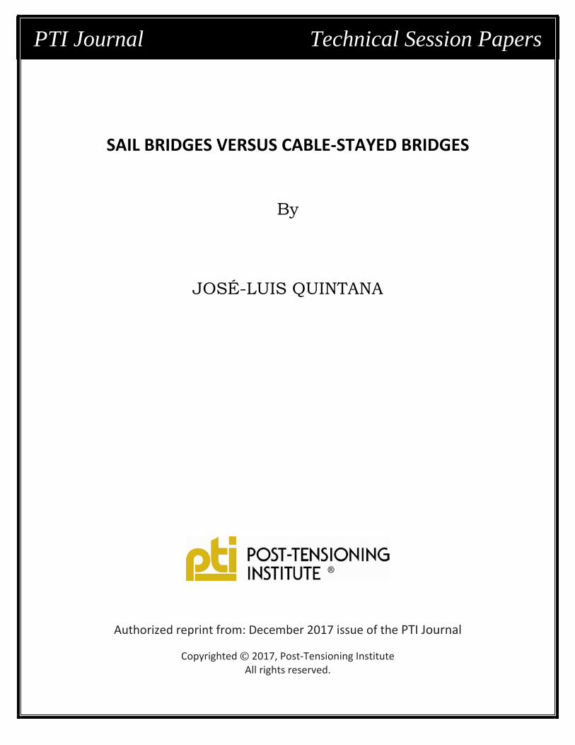
INTRODUCTIONThe recent construction of the Barra Vieja Bridge
near Acapulco, Mexico, has brought an opportunity to compare figures and experiences between cable-stayed or extradosed techniques (CS), and the sail bridge (SB) concept that was adopted for this structure.
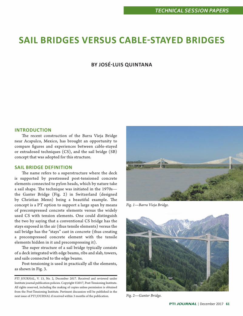
SAIL BRIDGE DEFINITIONThe name refers to a superstructure where the deck
is supported by prestressed post-tensioned concrete elements connected to pylon heads, which by nature take a sail shape. The technique was initiated in the 1970s— the Ganter Bridge (Fig. 2) in Switzerland (designed by Christian Menn) being a beautiful example. The concept is a PT option to support a large span by means of precompressed concrete elements versus the widely used CS with tension elements. One could distinguish the two by saying that a conventional CS bridge has the stays exposed in the air (thus tensile elements) versus the sail bridge has the “stays” cast in concrete (thus creating a precompressed concrete element with the tensile elements hidden in it and precompressing it).
The super structure of a sail bridge typically consists of a deck integrated with edge beams, ribs and slab, towers, and sails connected to the edge beams.
Post-tensioning is used in practically all the elements, as shown in Fig. 3.
Fig. 1—Barra Vieja Bridge.
Fig. 2—Ganter Bridge.
TECHNICAL SESSION PAPERS
62 December 2017 | PTI JOURNAL
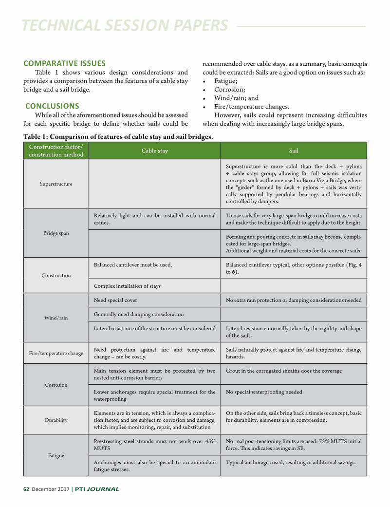
Table 1: Comparison of features of cable stay and sail bridges.Construction factor/construction method Cable stay Sail
Superstructure
Superstructure is more solid than the deck + pylons + cable stays group, allowing for full seismic isolation concepts such as the one used in Barra Vieja Bridge, where the “girder” formed by deck + pylons + sails was verti-cally supported by pendular bearings and horizontally controlled by dampers.
Bridge span
Relatively light and can be installed with normal cranes.
To use sails for very large-span bridges could increase costs and make the technique difficult to apply due to the height.
Forming and pouring concrete in sails may become compli-cated for large-span bridges. Additional weight and material costs for the concrete sails.
Construction
Balanced cantilever must be used. Balanced cantilever typical, other options possible (Fig. 4 to 6).
Complex installation of stays
Wind/rain
Need special cover No extra rain protection or damping considerations needed
Generally need damping consideration
Lateral resistance of the structure must be considered Lateral resistance normally taken by the rigidity and shape of the sails.
Fire/temperature change Need protection against fire and temperature change – can be costly.
Sails naturally protect against fire and temperature change hazards.
Corrosion
Main tension element must be protected by two nested anti-corrosion barriers
Grout in the corrugated sheaths does the coverage
Lower anchorages require special treatment for the waterproofing
No special waterproofing needed.
DurabilityElements are in tension, which is always a complica-tion factor, and are subject to corrosion and damage, which implies monitoring, repair, and substitution
On the other side, sails bring back a timeless concept, basic for durability: elements are in compression.
Fatigue
Prestressing steel strands must not work over 45% MUTS
Normal post-tensioning limits are used: 75% MUTS initial force. This indicates savings in SB.
Anchorages must also be special to accommodate fatigue stresses.
Typical anchorages used, resulting in additional savings.
COMPARATIVE ISSUESTable 1 shows various design considerations and
provides a comparison between the features of a cable stay bridge and a sail bridge.
CONCLUSIONSWhile all of the aforementioned issues should be assessed
for each specific bridge to define whether sails could be
recommended over cable stays, as a summary, basic concepts could be extracted: Sails are a good option on issues such as:• Fatigue;• Corrosion;• Wind/rain; and• Fire/temperature changes.
However, sails could represent increasing difficulties when dealing with increasingly large bridge spans.

TECHNICAL SESSION PAPERS TECHNICAL SESSION PAPERS
PTI JOURNAL | December 2017 63
Fig. 3—PT (indicated in red) used in practically all the elements of the sail bridge.
Fig. 4—Barra Vieja Bridge.
Fig. 5—Barra Vieja Bridge shows how deck was incrementally launched over temporary bents, including the preparations for the connection of the sails to the edge beams, which meant all the PT installation work could be done comfortably in the casting yard.
José-Luis Quintana has been the president of Mexpresa, since 1996. Mexpresa is a Mexico City based company devoted to the development and site implementation of bridge post-tensioning and erection systems. He has a Masters in civil engineering and 30 years’ experience in structures.
Fig. 6—Stressing the sails.