saline chlorinator - waterzone.mx · 5000 ppm added to the pool. ... event of low salt and can be...
TRANSCRIPT
ChlorSM Series
SALINE CHLORINATOR
Installation, Operation, and Maintenance Manual
SM Install Manual Page 2 of 35 05/05/2016
TABLE OF CONTENTS 1.0 DESCRIPTION 3
1.1 General Information 3
1.2 Principals of Operation 3
1.3 General Specifications and Sizing Guidelines 4
2.0 INSTALLATION 8
2.1 Unpacking 8
2.2 Storage 8
2.3 Safety Considerations 8
2.4 Plan Ahead 10
2.5 Additional Parts Required for Installation 10
2.6 Installation Diagram 11
2.7 Power Supply Installation 12
2.8 Electrolytic Cell Installation 12
2.9 Install Kit Installation 13
2.10 Plumbing the System 16
2.11 Plumbing the Power Supply Cooling Lines 16
2.12 System Wiring 17
2.13 Instructions for Adding a Salt Feed Relay 19
2.14 Electrolytic Cell Wiring 19
2.15 Bonding the System 19
3.0 OPERATION 20
3.1 Preparing the Water 20
3.2 Starting the System 20
3.3 System Operation 21
3.4 Display Information 21
4.0 MAINTENANCE 27
4.1 Acid Wash Operation 30
5.0 WARRANTY INFORMATION 34
Note: This manual is subject to change at any time based on system improvements, design changes, authorized modifications or new information. Please consult ChlorKing for the latest revision.
Manufacturer: ChlorKing Inc 6767 Peachtree Industrial Blvd. Norcross, GA 30092 1-800-536-8180

SM Install Manual Page 3 of 35 05/05/2016
SECTION 1 DESCRIPTION
1.1 GENERAL INFORMATION The ChlorKing® SM Series Saline Chlorination system is the most electrically efficient on-site sodium hypochlorite generator offered by ChlorKing®. The system is designed for commercial swimming pool applications and is capable of producing up to 28 pounds of equivalent chlorine per day. The system manufactures bleach continuously from a salt concentration of 3500 to 5000 ppm added to the pool. The ChlorKing® system is designed for commercial service and can be operated 24 hours a day or controlled by any pool controller. All models have digital displays that show system status, pool salt concentration, and temperature. Models are available in non-reverse and reverse polarity. 1.2 PRINCIPALS OF OPERATION
Electrolytic Cell Assembly The electrolytic cell assembly consists of a clear PVC cell housing containing an electrolytic cell made from precious metal coated cell plates. Pool water from the pool circulation system is directed through the cell in an off-line installation. The pool water, maintained between 3500 and 5000 ppm salt concentration is converted in the electrolytic cell to sodium hypochlorite. The sodium hypochlorite is then circulated to the pool and combines with organics and further combines to form salt to be used again by the electrolytic cell. This is called a closed loop system because the salt is used repeatedly and is only lost through splash-out, backwashing and rainfall. Power Supply and Control Box The power supply provides the current to the electrolytic cells to produce the rated amount of sodium hypochlorite. The power supply uses switched-mode technology, currently the most electrically efficient method of producing current for an electrolytic cell. The power supply houses all the safety features to prevent system operation in the event of a malfunction. Salt Control Salt control can be added to the ChlorKing® SM Series Chlorinator. The ChlorKing® SM Series Chlorinator monitors the salt concentration of the pool water and will only allow the system to generate chlorine if the salt concentration is above 3000 ppm to protect the system from low salt. The system uses a non-contacting torroidal sensor to monitor salt concentrations. The torroidal probe is connected to the power supply. The LCD displays the salt concentration. The controller is factory programmed to prevent chlorinator operation in the event of low salt and can be used to automate salt concentrations in the pool with the addition of a Saturated Salt Feeder, peristaltic pump, and relay box.
SM Install Manual Page 4 of 35 05/05/2016
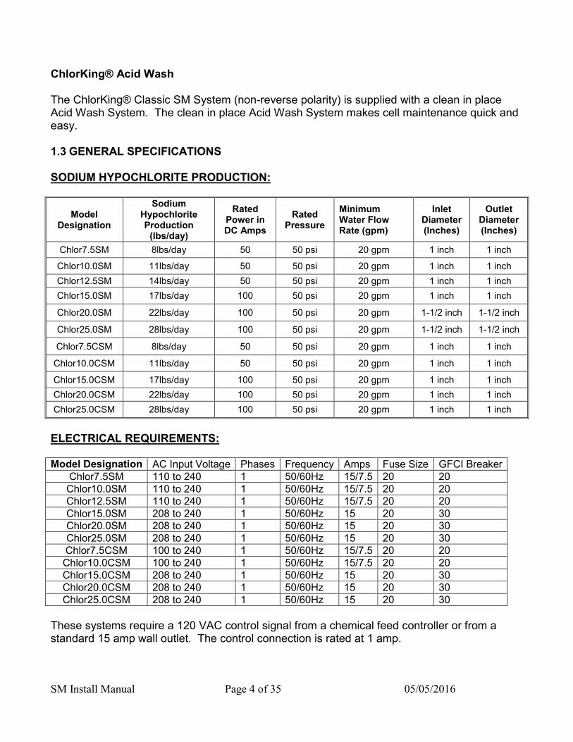
ChlorKing® Acid Wash The ChlorKing® Classic SM System (non-reverse polarity) is supplied with a clean in place Acid Wash System. The clean in place Acid Wash System makes cell maintenance quick and easy. 1.3 GENERAL SPECIFICATIONS SODIUM HYPOCHLORITE PRODUCTION:
Model Designation
Sodium Hypochlorite Production
(lbs/day)
Rated Power in DC Amps
Rated Pressure
Minimum Water Flow Rate (gpm)
Inlet Diameter (Inches)
Outlet Diameter (Inches)
Chlor7.5SM 8lbs/day 50 50 psi 20 gpm 1 inch 1 inch
Chlor10.0SM 11lbs/day 50 50 psi 20 gpm 1 inch 1 inch
Chlor12.5SM 14lbs/day 50 50 psi 20 gpm 1 inch 1 inch
Chlor15.0SM 17lbs/day 100 50 psi 20 gpm 1 inch 1 inch
Chlor20.0SM 22lbs/day 100 50 psi 20 gpm 1-1/2 inch 1-1/2 inch
Chlor25.0SM 28lbs/day 100 50 psi 20 gpm 1-1/2 inch 1-1/2 inch
Chlor7.5CSM 8lbs/day 50 50 psi 20 gpm 1 inch 1 inch
Chlor10.0CSM 11lbs/day 50 50 psi 20 gpm 1 inch 1 inch
Chlor15.0CSM 17lbs/day 100 50 psi 20 gpm 1 inch 1 inch
Chlor20.0CSM 22lbs/day 100 50 psi 20 gpm 1 inch 1 inch
Chlor25.0CSM 28lbs/day 100 50 psi 20 gpm 1 inch 1 inch
ELECTRICAL REQUIREMENTS:
These systems require a 120 VAC control signal from a chemical feed controller or from a standard 15 amp wall outlet. The control connection is rated at 1 amp.
Model Designation AC Input Voltage Phases Frequency Amps Fuse Size GFCI Breaker Chlor7.5SM 110 to 240 1 50/60Hz 15/7.5 20 20 Chlor10.0SM 110 to 240 1 50/60Hz 15/7.5 20 20 Chlor12.5SM 110 to 240 1 50/60Hz 15/7.5 20 20 Chlor15.0SM 208 to 240 1 50/60Hz 15 20 30 Chlor20.0SM 208 to 240 1 50/60Hz 15 20 30 Chlor25.0SM 208 to 240 1 50/60Hz 15 20 30 Chlor7.5CSM 100 to 240 1 50/60Hz 15/7.5 20 20 Chlor10.0CSM 100 to 240 1 50/60Hz 15/7.5 20 20 Chlor15.0CSM 208 to 240 1 50/60Hz 15 20 30 Chlor20.0CSM 208 to 240 1 50/60Hz 15 20 30 Chlor25.0CSM 208 to 240 1 50/60Hz 15 20 30

SM Install Manual Page 5 of 35 05/05/2016
SPACE REQUIREMENTS:
CHLOR7.5CSM AND CHLOR10.0CSM
CHLOR7.5SM AND CHLOR10.0SM
Cooling WaterLines
DC Power toCell
20
16
11
15
6"CellTube
11
27
6"Cell
Tube
Cooling WaterLines
DC Power toCell
20
16
SM Install Manual Page 6 of 35 05/05/2016
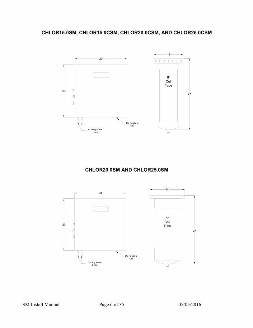
CHLOR15.0SM, CHLOR15.0CSM, CHLOR20.0CSM, AND CHLOR25.0CSM
CHLOR20.0SM AND CHLOR25.0SM
Cooling WaterLines
DC Power toCell
20
20
27
14
8"CellTube
Cooling WaterLines
DC Power toCell
11
27
6"CellTube
20
20

SM Install Manual Page 7 of 35 05/05/2016
SIZING GUIDELINES Chlorinator sizing must comply with local codes. Please contact your local health department for specific requirements or contact your local ChlorKing® representative for assistance. HEAD LOSS DATA
0.00
20.88
37.15
61.7
88.6
0.00
10.00
20.00
30.00
40.00
50.00
60.00
70.00
80.00
90.00
100.00
Head Loss Data for Chlor-25.0C. Head loss data reported in ft H2O as measured by NSF. Chlor-7.5, Chlor-10.0, Chlor-15.0, Chlor-5.0C, Chlor-7.5C, Chlor-10.0C, Chlor-15.0C, Chlor-20.0C, Chlor-25.0C similar.
SM Install Manual Page 8 of 35 05/05/2016
SECTION 2 INSTALLATION
2.1 UNPACKING Units are shipped from the factory. In the event of damages during shipping, it is the responsibility of the customer to notify the carrier immediately and to file a damage claim. Open the crate carefully and examine all material inside. Check against the parts list to be sure that all items are accounted for and intact. 2.2 STORAGE When storing units, use the original packaging and store under a shelter to protect the contents from weather. 2.3 SAFETY CONSIDERATIONS
IMPORTANT SAFETY INSTRUCTIONS READ AND FOLLOW ALL INSTRUCTIONS
SAVE THESE INSTRUCTIONS WHEN INSTALLING, OPERATING, AND MAINTAINING THIS EQUIPMENT, KEEP SAFETY CONSIDERATIONS FOREMOST. USE PROPER TOOLS, PROTECTIVE CLOTHING, AND EYE PROTECTION WHEN WORKING ON OR INSTALLING THE EQUIPMENT. FOLLOW THE INSTRUCTIONS IN THIS MANUAL AND TAKE ANY ADDITIONAL SAFETY MEASURES APPROPRIATE. BE EXTREMELY CAREFUL IN THE PRESENCE OF HAZARDOUS SUBSTANCES. THE PERSONNEL RESPONSIBLE FOR INSTALLATION, OPERATION, AND MAINTENANCE OF THIS EQUIPMENT MUST BE FULLY FAMILIAR WITH THE CONTENTS OF THIS MANUAL. ANY SERVICING OF THIS EQUIPMENT MUST BE DONE WITH THE UNIT FULLY OFF AND DISCONNECTED FROM THE POWER SOURCE AND ALL PRESSURE BLED FROM THE LIQUID LINES.
WARNING
CHLORKING® SYSTEMS ARE INTENDED TO BE INSTALLED ACCORDING TO ALL LOCAL AND NATIONAL REGULATIONS.
CONNECT THE EQUIPMENT ASSEMBLY TO A CIRCUIT PROTECTED BY A GROUND-FAULT CIRCUIT-INTERRUPTER.
ONLY A CERTIFIED TECHNICIAN MAY INSTALL AND SERVICE THE CHLORKING® SYSTEM.

SM Install Manual Page 9 of 35 05/05/2016
MODIFYING THE CHLORKING® SYSTEM IN ANY WAY MAY CAUSE BODILY INJURY AND WILL VOID THE WARRANTY.
DO NOT ALLOW CHILDREN TO OPERATE THE CHLORKING® SYSTEM. ONLY REPLACE COMPONENTS WITH THOSE SPECIFIED BY THE
MANUFACTURER. WHEN INSTALLING THE SYSTEM, ENSURE THAT POWER IS LINKED TO THE
MAIN PUMP POWER SOURCE FOR THE POOL TO ENSURE THAT THE CHLORKING® SYSTEM NEVER OPERATES WHEN THE PUMPS ARE OFF.
ALL BOXES ON THE CHLORKING® SYSTEM CONTAIN HIGH VOLTAGE COMPONENTS. NEVER OPEN ANY BOX WHILE THE POWER IS ON.
THE SYSTEM HAS THE POTENTIAL TO RELEASE HIGH DOSES OF CHORINE. USE CAUTION WHEN HANDLING, SERVICING, OR OPERATING THE EQUIPMENT.
DO NOT ENERGIZE OR OPERATE THE SYSTEM IF THE CELL HOUSING IS DAMAGED OR IMPROPERLY ASSEMBLED.
CORD CONNECTED AT TIME OF MANUFACTURE
o DANGER – Risk of injury Replace damaged cord immediately Do not bury cord
CONSIGNES DE SÉCURITÉ IMPORTANTES LISEZ ET SUIVEZ TOUTES LES INSTRUCTIONS
CONSERVEZ CES INSTRUCTIONS LORS DE L'INSTALLATION, DE FONCTIONNEMENT ET L'ENTRETIEN DE CET ÉQUIPEMENT, GARDEZ LES CONSIDÉRATIONS SUR LA SÉCURITÉ AVANT TOUT. UTILISER DES OUTILS APPROPRIÉS, DES VÊTEMENTS DE PROTECTION ET LUNETTES DE PROTECTION LORSQU'ILS TRAVAILLENT SUR OU À L'INSTALLATION. SUIVEZ LES INSTRUCTIONS DE CE MANUEL ET PREND LES MESURES DE SÉCURITÉ SUPPLÉMENTAIRES APPROPRIÉES. SOYEZ VIGILANTS EN PRÉSENCE DE SUBSTANCES DANGEREUSES. LE PERSONNEL CHARGÉ DE L'INSTALLATION, DE FONCTIONNEMENT ET D'ENTRETIEN DE CE MATÉRIEL DOIT ÊTRE PARFAITEMENT FAMILIARISÉ AVEC LE CONTENU DE CE MANUEL. AUCUNE OPÉRATION DE MAINTENANCE DE CET ÉQUIPEMENT DOIT ÊTRE FAITE AVEC L'UNITÉ ENTIÈREMENT ÉTEINT ET DÉBRANCHÉE DE L'ÉLECTRICITÉ ET TOUTE LA PRESSION SAIGNÉ À PARTIR DES LIGNES DE LIQUIDES.
MISE EN GARDE
CHLORKING ® SYSTEMES SONT DESTINES A ETRE INSTALLES SELON TOUS
LES REGLEMENTS LOCAUX ET NATIONAUX.
SM Install Manual Page 10 of 35 05/05/2016
CONNECTER LE MONTAGE DE L'ÉQUIPEMENT SUR UN CIRCUIT PROTÉGÉ PAR UN DISJONCTEUR DE FUITE À LA TERRE.
SEUL UN TECHNICIEN CERTIFIE PEUT INSTALLER ET ENTRETENIR LE CHLORKING ® SYSTEM.
MODIFIANT LA CHLORKING ® SYSTEM EN QUELQUE SORTE PEUT CAUSER DES LESIONS CORPORELLES ET LA GARANTIE ANNULATION.
NE LAISSEZ PAS LES ENFANTS A EXPLOITER LE CHLORKING ® SYSTEM. REMPLACEZ UNIQUEMENT LES COMPOSANTS AVEC CELLES SPÉCIFIÉES PAR
LE FABRICANT. LORSQUE VOUS INSTALLEZ LE SYSTEME, S'ASSURER QUE LA PUISSANCE
EST LIEE A LA SOURCE D'ALIMENTATION DE POMPE A MAIN POUR LA PISCINE POUR VOUS ASSURER QUE LE SYSTEME CHLORKING ® FONCTIONNE JAMAIS QUAND LES POMPES SONT HORS SERVICE.
TOUTES LES CASES SUR LE CHLORKING ® SYSTEME CONTIENNENT DES COMPOSANTS HAUTE TENSION. NE JAMAIS OUVRIR N'IMPORTE QUELLE BOÎTE TANDIS QUE L'APPAREIL EST ALLUMÉ.
LE SYSTÈME A LA POSSIBILITÉ DE LIBÉRER DES DOSES ÉLEVÉES DE CHLORE. SOYEZ PRUDENT LORS DE MANIPULATION, ENTRETIEN OU FONCTIONNEMENT DE L'ÉQUIPEMENT.
NE PAS METTRE SOUS TENSION OU FAIRE FONCTIONNER LE SYSTÈME SI LE BOÎTIER DE LA CELLULE EST ENDOMMAGÉ OU MAL ASSEMBLÉ.
CORDON CONNECTE AU MOMENT DE LA FABRICATION
o DANGER-RISQUE DE BLESSURE REMPLACEZ IMMEDIATEMENT LE CORDON D'ALIMENTATION NE PAS ENFOUIR LE CORDON
2.4 PLAN AHEAD Almost every pump room encountered is different. It is imperative to have prior knowledge of the facility in which the unit is to be installed and to evaluate what type of tools, wall anchors, etc. will be needed to make the installation as problem free as possible. 2.5 ADDITIONAL PARTS REQUIRED FOR INSTALLATION Polypropylene tubing, both ½ and 3/8 inch 1 or 1-1/2 inch PVC tubing or pipe PVC fittings as needed Anchors and mounting hardware

SM Install Manual Page 11 of 35 05/05/2016
2.6 INSTALLATION DIAGRAM
Suction LineFrom Pool
Filter
Waste Line
HeatExchanger
Pump
Strainer
FlowSensor
Ele
ctro
de
Sta
ckReturnLine
Power Supply Cooling Line
Power Supply
Ball Valve
Ball Valve
Ball Valve
SaltSensor
Bonding Lug
Pump ( Optional)
Disconnect
RatedVAC In
See Table
Control Cord
Controller
SM Install Manual Page 12 of 35 05/05/2016
2.7 POWER SUPPLY INSTALLATION
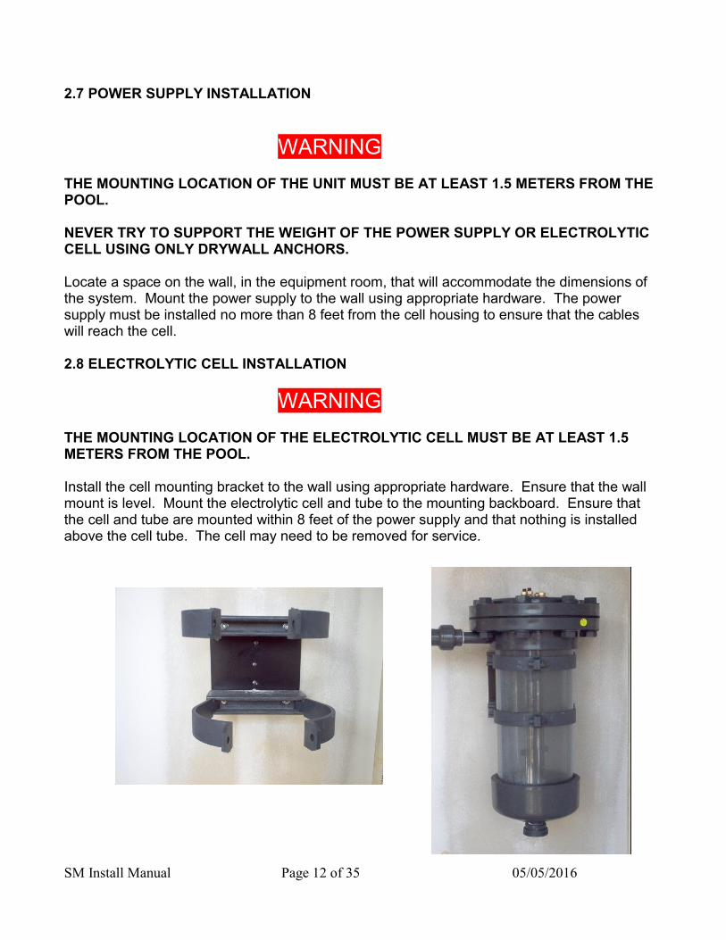
WARNING THE MOUNTING LOCATION OF THE UNIT MUST BE AT LEAST 1.5 METERS FROM THE POOL. NEVER TRY TO SUPPORT THE WEIGHT OF THE POWER SUPPLY OR ELECTROLYTIC CELL USING ONLY DRYWALL ANCHORS. Locate a space on the wall, in the equipment room, that will accommodate the dimensions of the system. Mount the power supply to the wall using appropriate hardware. The power supply must be installed no more than 8 feet from the cell housing to ensure that the cables will reach the cell. 2.8 ELECTROLYTIC CELL INSTALLATION
WARNING THE MOUNTING LOCATION OF THE ELECTROLYTIC CELL MUST BE AT LEAST 1.5 METERS FROM THE POOL.
Install the cell mounting bracket to the wall using appropriate hardware. Ensure that the wall mount is level. Mount the electrolytic cell and tube to the mounting backboard. Ensure that the cell and tube are mounted within 8 feet of the power supply and that nothing is installed above the cell tube. The cell may need to be removed for service.

SM Install Manual Page 13 of 35 05/05/2016
2.9 INSTALL KIT INSTALLATION Install the parts found in the installation kit in the order shown in the following diagram. NOTE: The flow switch must be installed with the arrow facing the bottom of the cell tube.
Chlor7.5SM, Chlor10.0SM, Chlor15.0SM
Assembly Diagram

SM Install Manual Page 14 of 35 05/05/2016
Chlor20.0SM, Chlor25.0SM Assembly Diagram

SM Install Manual Page 15 of 35 05/05/2016
Chor7.5CSM, Chlor10.0CSM, Chlor15.0CSM, Chlor20.0CSM, Chlor25.0CSM
Assembly Diagram

SM Install Manual Page 16 of 35 05/05/2016
2.10 PLUMBING THE SYSTEM Chlorking® systems require a minimum of 20 gpm of flow through the electrolytic cell to achieve the rated production of chlorine. The cell housing is plumbed using a bypass to achieve the 20 gpm of flow required. The cell housing must be installed as the last component in the return line of the pool, after all other equipment. See the plumbing diagram below.
2.11 PLUMBING THE POWER SUPPLY COOLING LINES
The power supply cooling lines are plumbed from the return line to pump suction. The cooler lines on the power supply will accommodate 3/8 inch tubing. NOTE: If a chemical feed controller is being used, the same 3/8 inch tubing can be used for both the sample cell and power supply cooling. Plumb the tubing from the return line into the controller sample cell, then from the sample cell to the power supply cooler, and from the cooler to pump suction.
Suction LineFrom Pool
Filter
Waste Line
HeatExchanger
Pump
Strainer
FlowSensor
Ele
ctro
de
Sta
ck
ReturnLine
Power Supply Cooling Line
Power Supply
Ball Valve
Ball Valve
Ball Valve
SaltSensor
Pump ( Optional)
DisconnectController

SM Install Manual Page 17 of 35 05/05/2016
2.12 SYSTEM WIRING
WARNING
THE EARTH TERMINALS AND THE EQUIPMENT BONDING WIRE MUST BE CONNECTED. THE ELECTRICAL SUPPLY MUST MATCH THE SYSTEM RATED VOLTAGE AND CURRENT. ENSURE THAT POWER IS LINKED TO THE MAIN PUMP POWER SOURCE FOR THE POOL TO ENSURE THAT THE CHLORKING® SYSTEM NEVER OPERATES WHEN THE POOL PUMPS ARE OFF. For ease of service it is recommended that a manual disconnect box be installed between the electrical service and the system. Connect the electrical supply from the pool equipment room to the terminal block on the lower left side of the power supply enclosure. Ensure that the electrical service is protected by a ground fault circuit interrupter and is rated for the model that is installed. Chlor7.5 models to Chlor12.5 models can be wired with 110V or 208/240V. Chlor15.0 models to Chlor25.0 models use 208/240V only. See Electrical Requirements on page 4 for details. 7.5 Through 12.5: 110V 7.5 Through 12.5: 208/240V
Line (Black)
Neutral (White)
Ground (Green)
Ground (Green)
Line 2 (Red)
Line 1 (Black)
SM Install Manual Page 18 of 35 05/05/2016
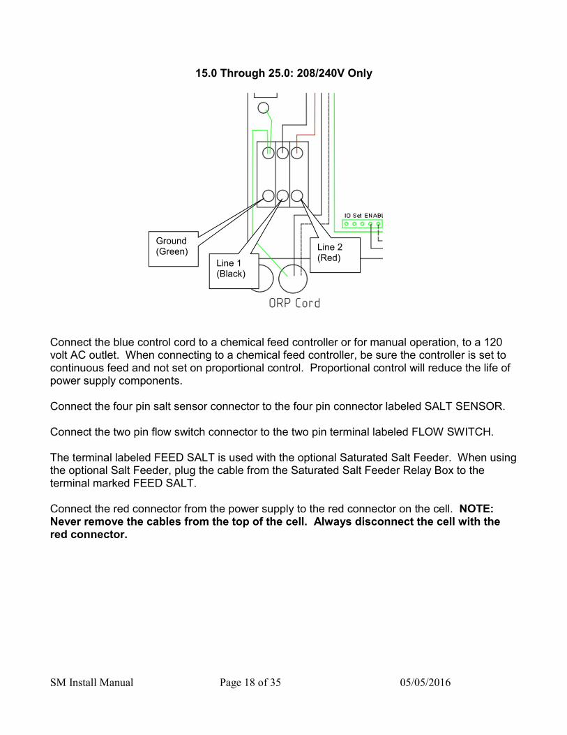
15.0 Through 25.0: 208/240V Only
Connect the blue control cord to a chemical feed controller or for manual operation, to a 120 volt AC outlet. When connecting to a chemical feed controller, be sure the controller is set to continuous feed and not set on proportional control. Proportional control will reduce the life of power supply components. Connect the four pin salt sensor connector to the four pin connector labeled SALT SENSOR. Connect the two pin flow switch connector to the two pin terminal labeled FLOW SWITCH. The terminal labeled FEED SALT is used with the optional Saturated Salt Feeder. When using the optional Salt Feeder, plug the cable from the Saturated Salt Feeder Relay Box to the terminal marked FEED SALT. Connect the red connector from the power supply to the red connector on the cell. NOTE: Never remove the cables from the top of the cell. Always disconnect the cell with the red connector.
Ground (Green)
Line 1 (Black)
Line 2 (Red)

SM Install Manual Page 19 of 35 05/05/2016
2.13 INSTRUCTIONS FOR ADDING A SALT FEED RELAY Mount the salt feed relay box to the wall close enough to the power supply so that the patch cord will connect to the FEED SALT connector on the power supply. Plug the relay box into a 120 VAC outlet. Plug the peristaltic pump used for feeding salt into the output plug on the relay box. 2.14 ELECTROLYTIC CELL WIRING Connect the red connector from the power supply to the red connector at the cell. NOTE: Never remove the cables from the top of the cell. Always disconnect the cell with the red connector. 2.15 BONDING THE SYSTEM All ChlorKing® systems include cell-bonding assemblies. These assemblies are included in the install kit. The bonding assemblies must be connected with a minimum of 8 AWG bonding wire. Connect the bonding wire from the top cell grounding assembly to the bottom cell grounding assembly and then from the bottom cell grounding assembly to the bonding lug located on the outside of the power supply. The bonding lugs on the power supply are clearly marked with a decal that reads “Bonding Lugs”. Connect the second bonding lug on the power supply to the bonding grid at the facility.

SM Install Manual Page 20 of 35 05/05/2016
SECTION 3 OPERATION
3.1 PREPARING THE WATER ChlorKing® saline chlorination systems operate by electrolyzing sodium chloride (salt) that has been added to the pool into sodium hypochlorite (liquid chlorine). In order for the ChlorKing® system to operate salt must be added directly to the pool at least 24 hours before the system is started. 40 pound of salt must be added for every 1,000 gallons of pool water to reach 5000 ppm (i.e.: a 50,000 gallon pool will require 2000 pounds of salt or 50 x 40 pound bags to reach 5000 ppm). Once the salt has been added, brush the surface of the pool continuously until the salt has dissolved. Never leave large amounts of salt on the surface of the pool. Only use pure NACl. Do not use salt with additives. Contact your dealer or ChlorKing® for a list of approved salt. Your pool water should be balanced in the following range before turning your ChlorKing® system on: Chlorine: 2 – 5 ppm Total Chlorine: No more than 0.5 ppm above free chlorine Ph: 7.2 – 7.6 Alkalinity: 80 – 120 Hardness: 180 – 280 ppm Salt: 3500 – 5000 ppm Cyanuric acid: 20 – 50 ppm (Outdoor Pools only) Phosphates: Less than 100 ppm Use standard test kits to check water chemistry, and use either a conductivity tester or salt test strip to check saline levels. (Note that most conductivity testers require frequent calibration to ensure accurate readings, failure to calibrate the equipment will result in inaccurate readings.) 3.2 STARTING THE SYSTEM Confirm that the salt concentration is 3500 to 5000 PPM. Confirm that the valves to and from the cell are in the open position and water is flowing through the cell tube. Make sure that water is flowing through the water-cooled heat sink.

SM Install Manual Page 21 of 35 05/05/2016
Ensure that the cord labeled ORP or Controller is plugged either into a controller or directly into a wall outlet. Be sure the disconnect box is in the on position. Confirm that the output control knob located on the left side of the power supply is turned fully clockwise. Depending on the model, the system will begin producing chlorine in 10 to 60 seconds. If the ChlorKing® system is linked to a chemical feed controller, adjust the output to the system maximum, which will allow for full production every time the controller calls for it. If the system is being operated manually, adjust the system to find the point at which chlorine levels are maintained to the desired level. This may take several days of monitoring. ChlorKing® systems connected to a chemical feed controller will only operate when the controller is in feed mode. Make sure that the chemical feed controller is not set in proportional mode or system damage may occur. 3.3 SYSTEM OPERATION ChlorKing® systems operate when both the main power supply and blue control cord have power applied to them. The ChlorKing® system will continue to operate for as long as power is applied from those two sources. The system has an output range of 5-100% of the rated chlorine production for the model installed and can be adjusted by turning the black knob on the side of power supply box in a clockwise or anti-clockwise direction.
3.4 DISPLAY INFORMATION During normal operation the display will have the following information available:

Saline Chlorinator Install Manual Page 22 of 35 1/20/15
This sceen is displayed when the system is waiting for a signal on the blue cord from an external source such as a chemical feed controller. The system will not generate chlorine until this signal is received.
The screen below is displayed when the system detects no flow through the electrolytic cell housing. This condition will stop the system from generating chorine. Once flow is restored, the system will start automatically and this screen will no longer be active.
Saline Chlorinator Install Manual Page 23 of 35 1/20/15
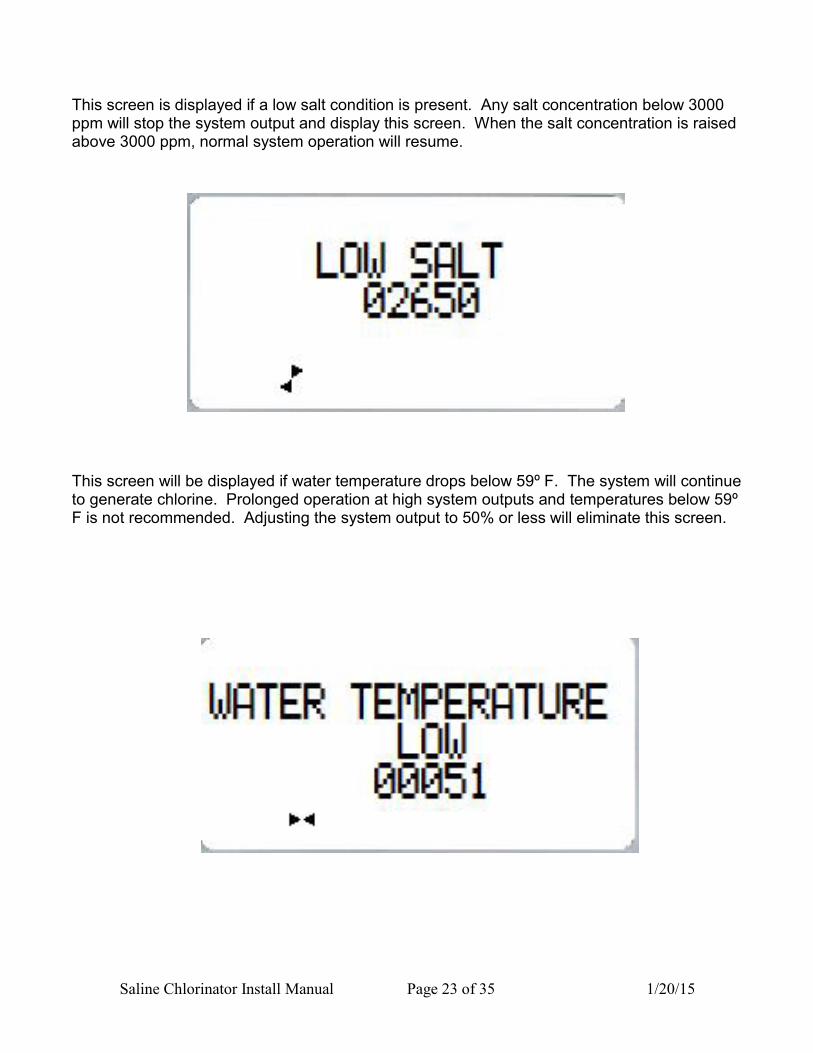
This screen is displayed if a low salt condition is present. Any salt concentration below 3000 ppm will stop the system output and display this screen. When the salt concentration is raised above 3000 ppm, normal system operation will resume.
This screen will be displayed if water temperature drops below 59º F. The system will continue to generate chlorine. Prolonged operation at high system outputs and temperatures below 59º F is not recommended. Adjusting the system output to 50% or less will eliminate this screen.

Saline Chlorinator Install Manual Page 24 of 35 1/20/15
The screen below indicates a disconnected or defective salt sensor. This screen will shut the system output off. Reconnect or replace the salt sensor to restore system operation.
In order to prevent the system from being cycled on and off rapidly, the system has start delay of 60 seconds. During this delay the screen below is displayed.

Saline Chlorinator Install Manual Page 25 of 35 1/20/15
The following screens are available by accessing the micro controller inside of the power supply.
WARNING
THE POWER SUPPLY CONTAINS HIGH VOLTAGE CIRCIUTS THAT CAN CAUSE INJURY OR DEATH. ONLY PERSONS CERTIFIED AND TRAINED TO SERVICE THESE UNITS SHOULD ACCESS THE FOLLOWING SCREENS. WHEN MAINTAINING THIS EQUIPMENT, KEEP SAFETY CONSIDERATIONS FOREMOST. USE PROPER TOOLS, PROTECTIVE CLOTHING, AND EYE PROTECTION WHEN WORKING ON THE EQUIPMENT. FOLLOW THE INSTRUCTIONS IN THIS MANUAL AND TAKE ANY ADDITIONAL SAFETY MEASURES APPROPRIATE. THE PERSONNEL RESPONSIBLE FOR MAINTENANCE OF THIS EQUIPMENT MUST BE FULLY FAMILIAR WITH THE CONTENTS OF THIS MANUAL. Daily system run time can be viewed by pressing and holding the “A” button on the microcontroller for 5 seconds.
Saline Chlorinator Install Manual Page 26 of 35 1/20/15
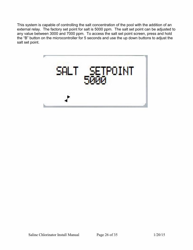
This system is capable of controlling the salt concentration of the pool with the addition of an external relay. The factory set point for salt is 5000 ppm. The salt set point can be adjusted to any value between 3000 and 7000 ppm. To access the salt set point screen, press and hold the “B” button on the microcontroller for 5 seconds and use the up down buttons to adjust the salt set point.

Saline Chlorinator Install Manual Page 27 of 35 1/20/15
SECTION 4 MAINTENANCE
ChlorKing® systems are designed to operate 24 hours a day and 7 days a week at maximum production rates and will give you years of trouble free use if you follow these basic maintenance and cleaning instructions. This system produces sodium hypochlorite “liquid chlorine” from the salt that you have added to the water. It will only continue to operate correctly if salt is maintained at a minimum 3500 ppm level. Low salt will lower the amount of chlorine produced, and cause damage to the electrolytic cell. When maintained properly the electrolytic cell has a life of 15,000 hours. (Warranty’s will not be honored if it is determined that salt has been run low.) The titanium plates that make up the cell will last 15,000 hours or more if properly maintained. By ensuring that salt is always at the correct level, and plates are cleaned regularly, you will ensure 15,000 hours of operation or more. Check salt concentration. Salt must be maintained at 3500 to 5000 ppm. Check salt as often as necessary to ensure the concentration. Adjust the salt concentration as often as needed to maintain the desired level. Test the flow switch for proper operation at least once a month and clean the strainer as often as needed. To test the flow switch, close the lower cell isolation valve stopping flow to the cell. Immediately check to see if the system shut off. If the system does not shut off, immediately open the valve. Do not allow the system to operate with the valve closed. Replace a defective flow switch immediately. To clean the strainer, disconnect power from the system, close the lower cell isolation valve and then close the upper cell isolation valve. Unscrew the strainer cover. Allow pressure to release slowly. Remove the strainer screen, clean the screen and reinstall.

Saline Chlorinator Install Manual Page 28 of 35 1/20/15
Evaluate the cell condition every week Visually inspect the cell tube for leaks and the cell stack for calcium build up. Check the connections at the top of cell and clean as needed.
This electrode stack is in excellent condition and does not require cleaning
A cell stack with calcium bridged plates.

Saline Chlorinator Install Manual Page 29 of 35 1/20/15
Clean the cell when calcium buildup is present (reverse polarity systems)
WARNING
Read all cautions and directions provided with the muriatic acid used. Always add acid to water. Use only with adequate ventilation. If strong odor is noticed, STOP, ventilation is inadequate. Leave area immediately. If the work area is not well ventilated you MUST use a properly fitted and maintained NIOSH approved respirator for acid fumes. To clean the cell manually, disconnect power from the system, close the lower cell isolation valve and then close the upper cell isolation valve. Disconnect the cables from electrolytic cell. Remove the bolts holding the electrolytic cell stack in the cell tube and lift the cell out of the cell tube. Immerse the cell in a solution with a 4 to 1 water and muriatic acid mixture. Leave the cell in the muriatic acid solution until the cell is clean. Do not leave the cell in the muriatic acid solution any longer than necessary to clean the cell. Reassemble the cell stack in the tube and reconnect the cables to the top of the cell stack.

Saline Chlorinator Install Manual Page 30 of 35 1/20/15
Clean the cell when calcium buildup is present with the ChlorKing® Acid Wash System (non-reverse polarity system)
WARNING
Read all cautions and directions provided with the muriatic acid used. Always add acid to water. Use only with adequate ventilation. If strong odor is noticed, STOP, ventilation is inadequate. Leave area immediately. If the work area is not well ventilated you MUST use a properly fitted and maintained NIOSH approved respirator for acid fumes. 4.1 Acid Wash Operation Turn off the power to the chlorinator to be serviced. Close the lower and upper cell tube ball valves [1] and [2]. Always close the lower ball valve [1] first to avoid damaging the cell tube. Open the lower and upper acid wash ball valves [3] and [4]. Drain the water from the cell tube.
2
1
4
3
Drain the water from the cell tube

Saline Chlorinator Install Manual Page 31 of 35 1/20/15
Connect the acid wash tank and pump to the acid
wash valves [3] and [4] as shown in the photo on
the right.
Fill the acid wash tank with 4 gallons of water and 1
gallon of muriatic acid.
Open the white wash valves [5] and [6]. Open the
tank feed valve [7].
Plug the Acid Wash pump in to a 120 VAC source and start the wash cycle. Allow the pump to run until the cell is clean.
When the cell is clean, leave the Acid Wash pump running and open the grey drain valves [8] and [9] and close the white wash valves [5] and [6]. The cell tube will now drain into the wash tank. When the cell is empty, unplug the pump immediately. Do not let the pump run dry.
6
5 7
3
4
9
8

Saline Chlorinator Install Manual Page 32 of 35 1/20/15
Close all acid wash valves [3], [4], [5], [6], [7], [8] and [9]. Open the 2 cell tube valves [1] and [2]. Restart the system.
NOTE: All acid wash valves must be closed prior to restarting the system or damage to the acid wash tank may occur.
9
3
2
1
7
5
6
8
4

Saline Chlorinator Install Manual Page 33 of 35 1/20/15
Visually inspect the power supply once every month.
Open the enclosure and visually check for any abnormal conditions such as burned wires, loose connections or corrosion. Operate the system to verify performance once every month. Turn the system on. Adjust the control knob to the full off position and note that the amps displayed on the meter go to zero. Adjust the control knob to the maximum position and verify that amps go to maximum. Adjust the control knob to the desired setting.

Saline Chlorinator Install Manual Page 34 of 35 1/20/15
SECTION 5 WARRANTY INFORMATION
The ChlorKing® system carries a limited 3-year warranty 3-year warranty on assembly of electrical components and production tank. 1 year on all electrical items. 2 years or 15,000 hours, whichever occurs first, pro-rated hourly, on titanium electrodes. (Year 1 is warranted fully, thereafter pro-rated warranty applies, applicable over the full 2-year period. Applicable on electrode stacks where full price has been paid.) ChlorKing® advises that titanium electrodes will have to be replaced every 15,000 hours of operating time. Under no circumstances shall the replacement titanium electrodes exceed the original 15,000-hour warranty. ChlorKing® warranties will not be honored should it be shown that the operating and maintenance procedures have not been followed, particularly with regard to the cleaning frequency program. ChlorKing® warranties of the titanium electrodes will not be honored if the system is operated in water temperatures lower than 59 degrees F. During the warranty period the customer shall return the defective component, freight prepaid, accompanied by the original invoice or proof of purchase, and ChlorKing® shall at its sole discretion elect to repair or replace the defective component and return it to the customer, freight pre-paid. ChlorKing® accepts no responsibility other than to repair or replace a defective component, and this warranty specifically excludes product failure due to accidental damage, abuse, misuse, and negligence, damage due to non-compliance of the operating manual or unauthorized alterations or modifications to the system. ChlorKing® accepts no responsibility and is not liable for any extended warranties or variations to this warranty offered by re-sellers of ChlorKing® systems.

Saline Chlorinator Install Manual Page 35 of 35 1/20/15
Warranty Registration Card Please complete and return to activate ChlorKing® warranty
Please mail or fax to ChlorKing® inc. P.O. Box 80823, Atlanta, GA, 30366 Fax: 770-685-6576
Dealer Name: _______________________________________________________
Address: _________________________________City:__________________
State: ______________________Zip:___________Tel:_____________________
Installation site of equipment:___________________________________________
Address: _________________________________City:__________________
State: ______________________Zip:___________
Date of purchase:__________________ Serial number:___________________
1. Pool size:______________________ 2. Pool finish:____________________
3. Indoor / Outdoor:________________ 4. Heated: Yes / no
5. Filter Type:_____________________ 6. Pool Age:_____________________
7. New or existing pool:_____________ 7. Controller installed: Yes / No
8. If controller installed, what make and model: _____________________________