sam0093 side-by-side refrigerator model · pdf file · 2016-02-14·cool air...
TRANSCRIPT
RS2544RS2622RS2644RS2666RS2777
Model:SIDE-BY-SIDE REFRIGERATOR
SAMSUNG Home Appliance Service
For the latest parts information,Please access to our service web site(http://www.e4buyer.com/refrigerator)
4
1. INTRODUCTION
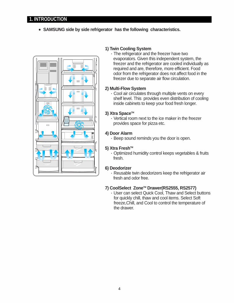
SAMSUNG side by side refrigerator has the following characteristics.
1) Twin Cooling System·The refrigerator and the freezer have two
evaporators. Given this independent system, the freezer and the refrigerator are cooled individually as required and are, therefore, more efficient. Food odor from the refrigerator does not affect food in the freezer due to separate air flow circulation.
2) Multi-Flow System·Cool air circulates through multiple vents on every
shelf level. This provides even distribution of cooling inside cabinets to keep your food fresh longer.
3) Xtra SpaceTM
·Vertical room next to the ice maker in the freezer provides space for pizza etc.
4) Door Alarm·Beep sound reminds you the door is open.
5) Xtra FreshTM
·Optimized humidity control keeps vegetables & fruits fresh.
6) Deodorizer·Reusable twin deodorizers keep the refrigerator air
fresh and odor free.
7) CoolSelect ZoneTM Drawer(RS2555, RS2577)·User can select Quick Cool, Thaw and Select buttons
for quickly chill, thaw and cool items. Select Soft freeze,Chill, and Cool to control the temperature of the drawer.

5
2. INSTALLATION
1) To protect refrigerator in movementUse padded hand truck as shown. If entrance width is less than 39〃, remove doors prior to installation and reattach doors according to procedure below.
2) Remove all protective tape and pad in refrigerators.Connect water lines and power cord. Adjust the clearance between the doors.
3) Set the temperature control to the temperature and wait for an hour.The refrigerator should get slightly chilled and the motor runs smoothly.
4) Once the refrigerator temperature is sufficiently lowYou can store food in the refrigerator. After starting the refrigerator, it takes a few hours to reach the appropriate temperature.
Removing Doors
Open the freezer and refrigerator doors, andthen take off the front leg cover assembly byturning the three screws counter-clockwise.Remove the screw from clamp disconnect, thewater tube by pressing the coupler, and pullingthe water tube away.
With the door closed, remove the upper hingecover using a screwdriver, and then disconnectthe wires. Remove hinge screws and groundscrew counter-clockwise, and take off the upperhinge. Take care removing the door to ensure thatit does not fall on you.
Remove the door from the lower hinge bycarefully lifting the door so as not to damage thewater tube. Remove the lower hinge from thelower hinge bracket by lifting the lower hinge.
Attaching Doors
Insert the lower hinge in the bracket lowerhinge. Attach the freezer door by inserting thehose in the lower side of the door into the hole inthe lower hinge and pulling the hose down.
Insert the upper hinge shaft into the hole. Afterleveling between the upper hinge hole and thehole of the cabinet. Reattach hinge screws andscrew in the clockwise direction. Connect thewires. Put the front part of the upper hinge coveron the front part of the upper hinge and reattachfrom the front part of the upper hinge cover first.
6
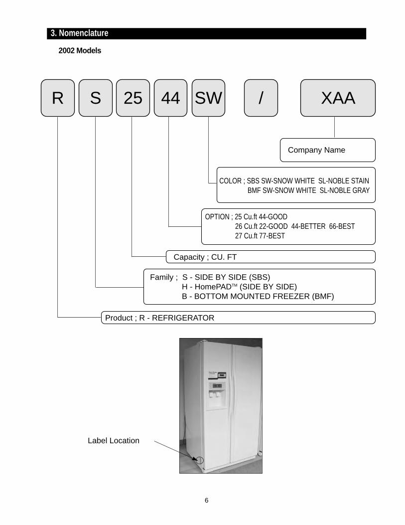
3. Nomenclature
2002 Models
R S 25 44 SW / XAA
Product ; R - REFRIGERATOR
Capacity ; CU. FT
Family ; S - SIDE BY SIDE (SBS)H - HomePADTM (SIDE BY SIDE)B - BOTTOM MOUNTED FREEZER (BMF)
OPTION ; 25 Cu.ft 44-GOOD26 Cu.ft 22-GOOD 44-BETTER 66-BEST27 Cu.ft 77-BEST
COLOR ; SBS SW-SNOW WHITE SL-NOBLE STAINBMF SW-SNOW WHITE SL-NOBLE GRAY
Company Name
Label Location
4. Specifications
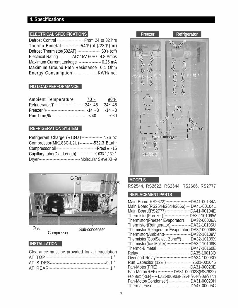
Defrost Control From 24 to 32 hrsThermo-Bimetal 54(off)/23(on) Defrost Thermistor(502AT) 50(off) Electrical Rating AC115V 60Hz, 4.8 AmpsMaximum Current Leakage 0.25 mAMaximum Ground Path Resistance 0.1 OhmEnergy Consumption KWH/mo.
Ambient Temperature 70 90Refrigerator, 34∼46 34∼46Freezer, -14∼8 -14∼8Run Time,% 40 60
Refrigerant Charge (R134a) 7.76 ozCompressor(MK183C-L2U) 532.3 Btu/hrCompressor oil Freol α-15Capillary tube(Dia, Length) 0.033"",130""Dryer Molecular Sieve XH-9
Clearance must be provided for air circulationAT TOP 1""AT SIDES 0.1""AT REAR 1""
RS2544, RS2622, RS2644, RS2666, RS2777
Main Board(RS2622) DA41-00134AMain Board(RS2544/2644/2666) DA41-00104LMain Board(RS2777) DA41-00104EThermistor(Freezer) DA32-10109WThermistor(Freezer Evaporator) DA32-00006AThermistor(Refrigerator) DA32-10105UThermistor(Refrigerator Evaporator) DA32-00006BThermistor(Ambient) DA32-10109VThermistor(CoolSelect ZoneTM) DA32-10109XThermistor(Ice-Maker) DA32-10108BThermo-Bimetal DA47-10160ERelay DA35-10013QOverload Relay DA34-10003DRun Capacitor (12) 2501-001045Fan-Motor(FRE) DA31-00020EFan-Motor(REF) DA31-00002S(RS2622)Fan-Motor(REF) DA31-00020E(RS2544/2644/2666/2777)Fan-Motor(Condenser) DA31-00020HThermal Fuse DA47-00095C
FanFanFanFanFanFan
(Air inlet)(Air inlet)(Air inlet)
(Air inlet)(Air inlet)(Air inlet)
Heat exchangerHeat exchangerHeat exchangerHeat exchanger
CompressorDryer
C-FanElectric box
Sub-condenser
ELECTRICAL SPECIFICATIONS Freezer Refrigerator
NO LOAD PERFORMANCE
REFRIGERATION SYSTEM
INSTALLATION
MODELS
REPLACEMENT PARTS
7
8
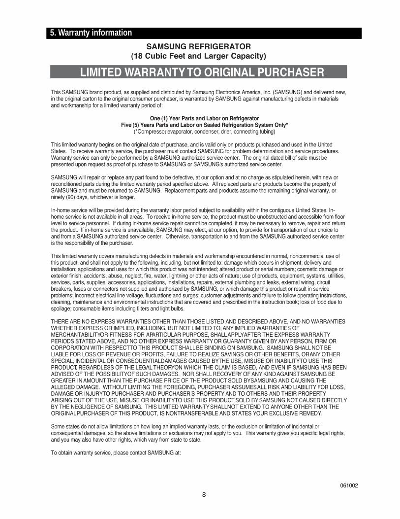
5. Warranty information

9
6. Interior Views and Dimensions
S2544/2622 Model S2777/2666 Modelith CoolSelectZoneTM
RS2644 Modelwith CoolSelectZoneTM
RS2666/2777)
RS2644/2666/2777)
RS2666/2777)
Chilled Bin)(RS2777)
6-1) Shelves and Bins
Freezer
Refrigerator
10
Interior Views and Dimensions
A
B
C
D E
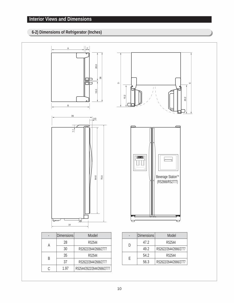
6-2) Dimensions of Refrigerator (Inches)
Beverage StationTM
(RS2666/RS2777)
- Dimensions Model
A
B
C
28
30
35
37
1.97
RS2544
RS2622/2644/2666/2777
RS2544
RS2622/2644/2666/2777
RS2544/2622/2644/2666/2777
- Dimensions Model
D
E
47.2
49.2
54.2
56.3
RS2544
RS2622/2644/2666/2777
RS2544
RS2622/2644/2666/2777
11
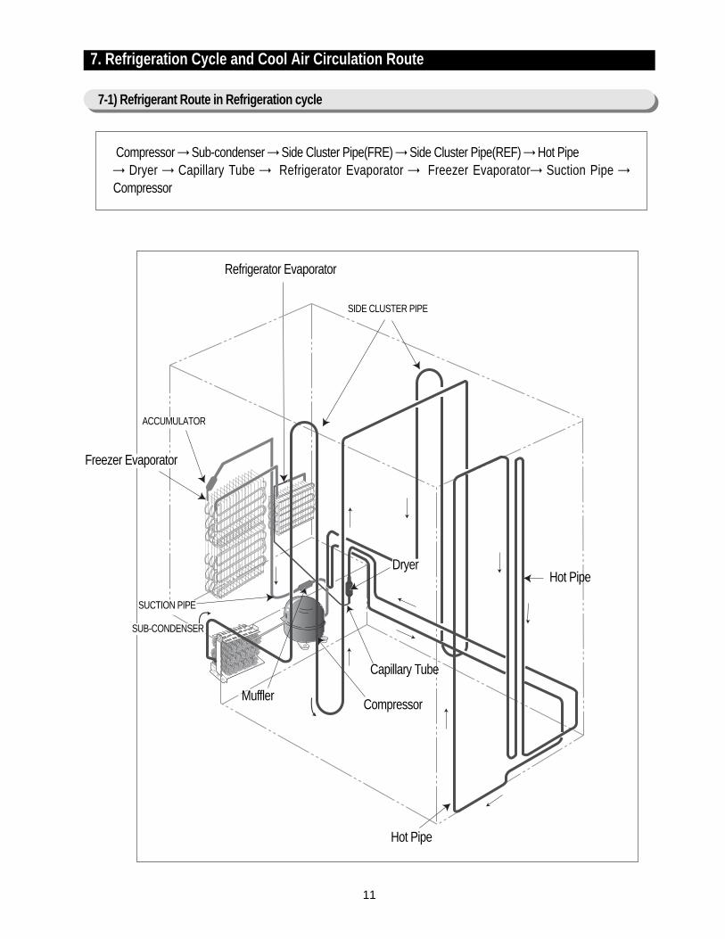
Compressor → Sub-condenser → Side Cluster Pipe(FRE) → Side Cluster Pipe(REF) → Hot Pipe → Dryer → Capillary Tube → Refrigerator Evaporator → Freezer Evaporator→ Suction Pipe →Compressor
Refrigerator Evaporator
Capillary Tube
ACCUMULATOR
Freezer Evaporator
SUCTION PIPE
Dryer
Muffler
SUB-CONDENSER
Hot Pipe
Hot Pipe
Compressor
SIDE CLUSTER PIPE
7. Refrigeration Cycle and Cool Air Circulation Route
7-1) Refrigerant Route in Refrigeration cycle
12
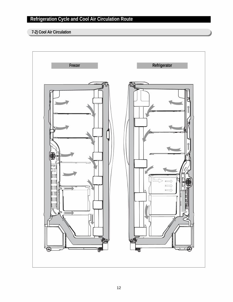
Refrigeration Cycle and Cool Air Circulation Route
7-2) Cool Air Circulation
Freezer Refrigerator
13
8-1) Refrigerator Disassembly
8-2) Freezer Disassembly
8-3) Machine Compartment Disassembly
8. Mechanical Disassembly
Control Panel ········································ 14Door Handle ········································ 14Beverage StationTM ····································· 14Door Gasket ········································· 14Refrigerator Door Light Switch ······························ 15Refrigerator Light ······································ 15Tempered Glass Shelf ··································· 15Plastic Drawers in Refrigerator ······························ 15Gallon Door Bin ······································· 15Water Filter ········································· 16Evaporator Cover in the Refrigerator ·························· 16Upper Ductwork ······································ 16Evaporator Fan Motor ··································· 16Evaporator in Refrigerator ································· 17Refrigerator Thermistor ·································· 17CoolSelect ZoneTM Thermistor ······························ 17
Door Bin in Freezer ···································· 18Freezer Door Light Switch ································ 18Plastic(Wire) Drawer in Freezer······························ 18Freezer Shelf ········································ 18Ice Dispenser & Ice Maker ································ 18Auger Motor Case ····································· 19Freezer Light ········································ 20Evaporator Cover in Freezer ······························· 20Upper Ductwork······································· 20Evaporator Fan Motor ··································· 20Evaporator in Freezer ··································· 21Freezer Thermistor ····································· 21Ambient Thermistor····································· 21Ice-Maker Thermistor···································· 21
Machine Compartment & Electrix Box ··························22Water Solenoids ······································ 22Condenser Fan ······································· 22Sub-condenser ······································· 22
14
88.. MMeecchhaanniiccaall DDiissaasssseemmbbllyy
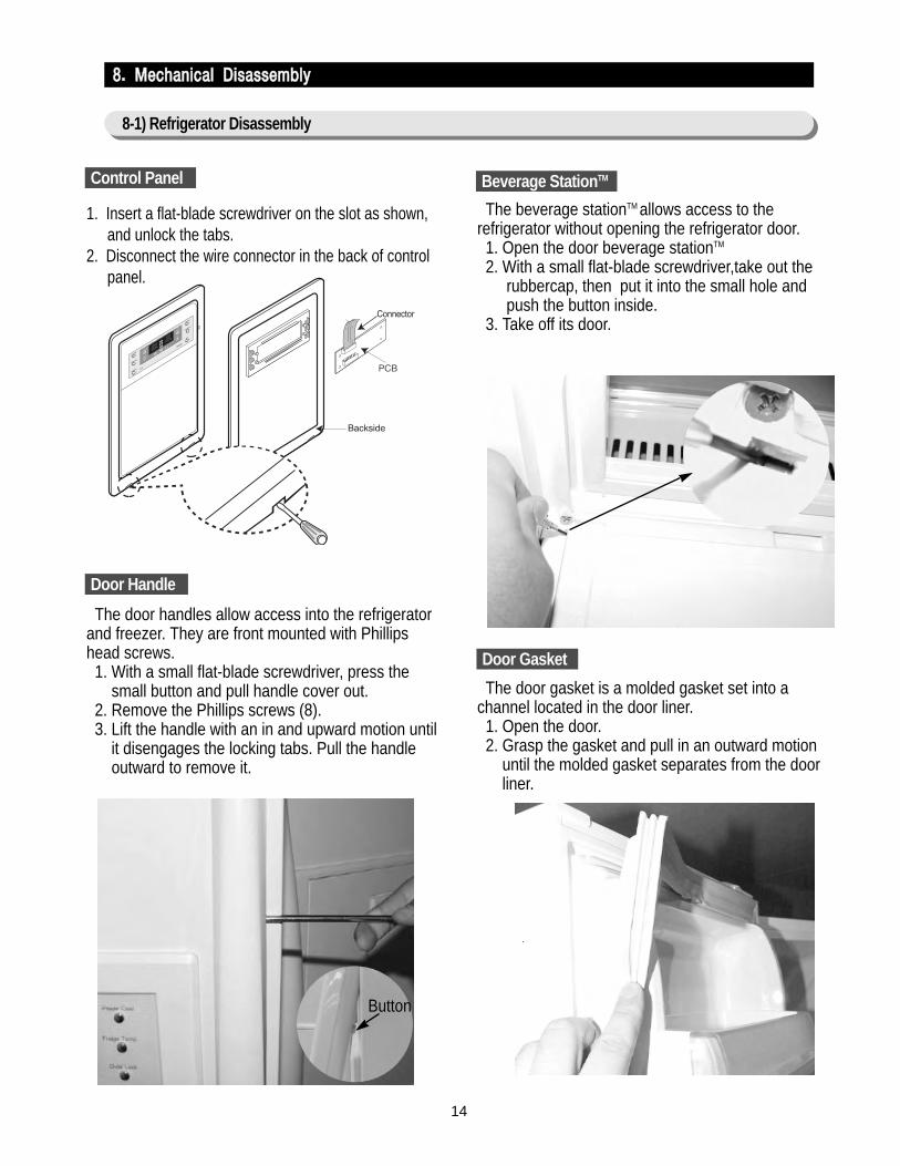
1. Insert a flat-blade screwdriver on the slot as shown,and unlock the tabs.
2. Disconnect the wire connector in the back of controlpanel.
The door handles allow access into the refrigeratorand freezer. They are front mounted with Phillipshead screws.
1. With a small flat-blade screwdriver, press the small button and pull handle cover out.
2. Remove the Phillips screws (8).3. Lift the handle with an in and upward motion until
it disengages the locking tabs. Pull the handle outward to remove it.
The beverage stationTM allows access to therefrigerator without opening the refrigerator door.
1. Open the door beverage stationTM
2. With a small flat-blade screwdriver,take out the rubbercap, then put it into the small hole and push the button inside.
3. Take off its door.
The door gasket is a molded gasket set into achannel located in the door liner.
1. Open the door.2. Grasp the gasket and pull in an outward motion
until the molded gasket separates from the door liner.
Control Panel
Door Handle
Beverage StationTM
Door Gasket
Button
8-1) Refrigerator Disassembly
15
MMeecchhaanniiccaall DDiissaasssseemmbbllyy
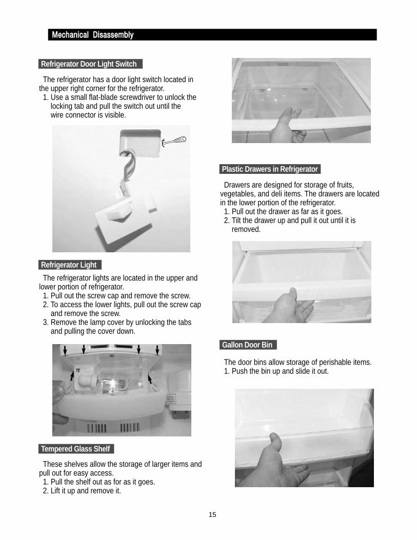
The refrigerator has a door light switch located inthe upper right corner for the refrigerator.
1. Use a small flat-blade screwdriver to unlock the locking tab and pull the switch out until the wire connector is visible.
The refrigerator lights are located in the upper andlower portion of refrigerator.
1. Pull out the screw cap and remove the screw.2. To access the lower lights, pull out the screw cap
and remove the screw.3. Remove the lamp cover by unlocking the tabs
and pulling the cover down.
These shelves allow the storage of larger items andpull out for easy access.
1. Pull the shelf out as for as it goes.2. Lift it up and remove it.
Drawers are designed for storage of fruits,vegetables, and deli items. The drawers are locatedin the lower portion of the refrigerator.
1. Pull out the drawer as far as it goes.2. Tilt the drawer up and pull it out until it is
removed.
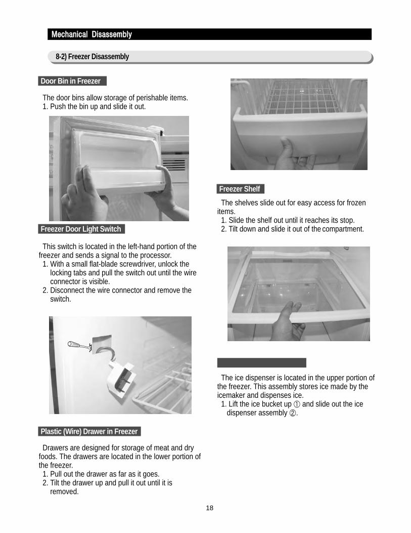
The door bins allow storage of perishable items.1. Push the bin up and slide it out.
Refrigerator Door Light Switch
Gallon Door Bin
Tempered Glass Shelf
Plastic Drawers in Refrigerator
Refrigerator Light

16
MMeecchhaanniiccaall DDiissaasssseemmbbllyy
The water filter is located in the upper right-handcorner of the refrigerator. The water filter filters waterfor the ice maker and the water dispenser.
1. Turn the water filter 1/2 turn counterclockwise and pull it down.
2. To install the filter, align the indication mark (unlock position) and push it up while turning 1/2 turn clockwise until the lock position is aligned. Do not over tighten.
1. Pull out the screw cap and remove the screw.2. Remove the lamp cover by unlocking the tabs
and pulling the cover down.3. Remove the water tank from the evaporator cover
by unscrewing the screws (2).4. Remove the screws (6) at the evaporator cover
and the two fixed screws of the wire connector cover.
5. Take off motor and lamp wire connector located on the upper liner.
6. Remove the duckwork of the evaporator fan in the direction of the arrow as shown.
1. Remove the screw caps (2) and screws (5).2. Slide the upper fan ductwork out while
disconnecting the wire connector(lamp and thermistor).
The evaporator fan is located in the middle rear ofthe freezer. This fan circulates cold air in the freezer.
1. Remove screws (4) located at the four corners of the fan bracket.
2. Take the fan motor assembly off.
Water Filter
Evaporator Cover in the Refrigerator
Upper Ductwork
Evaporator Fan Motor
17
MMeecchhaanniiccaall DDiissaasssseemmbbllyy
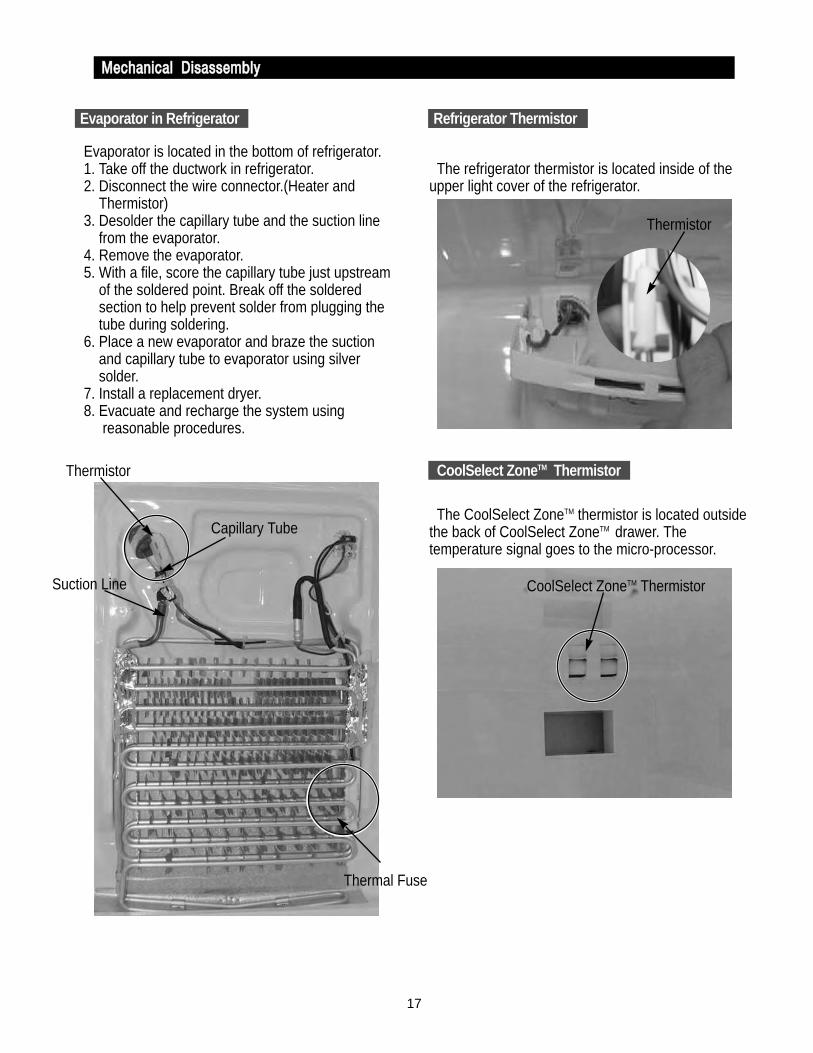
Evaporator is located in the bottom of refrigerator.1. Take off the ductwork in refrigerator.2. Disconnect the wire connector.(Heater and
Thermistor)3. Desolder the capillary tube and the suction line
from the evaporator.4. Remove the evaporator.5. With a file, score the capillary tube just upstream
of the soldered point. Break off the soldered section to help prevent solder from plugging the tube during soldering.
6. Place a new evaporator and braze the suction and capillary tube to evaporator using silver solder.
7. Install a replacement dryer.8. Evacuate and recharge the system using
reasonable procedures.
The refrigerator thermistor is located inside of theupper light cover of the refrigerator.
The CoolSelect ZoneTM thermistor is located outsidethe back of CoolSelect ZoneTM drawer. Thetemperature signal goes to the micro-processor.
Refrigerator ThermistorRefrigerator Thermistor
CoolSelect ZoneTM ThermistorThermistor
Thermistor
CoolSelect ZoneTM Thermistor Suction Line
Capillary Tube
Thermal Fuse
Evaporator in Refrigerator
18
The door bins allow storage of perishable items.1. Push the bin up and slide it out.
This switch is located in the left-hand portion of thefreezer and sends a signal to the processor.
1. With a small flat-blade screwdriver, unlock the locking tabs and pull the switch out until the wire connector is visible.
2. Disconnect the wire connector and remove the switch.
Drawers are designed for storage of meat and dryfoods. The drawers are located in the lower portion ofthe freezer.
1. Pull out the drawer as far as it goes.2. Tilt the drawer up and pull it out until it is
removed.
The shelves slide out for easy access for frozenitems.
1. Slide the shelf out until it reaches its stop.2. Tilt down and slide it out of the compartment.
The ice dispenser is located in the upper portion ofthe freezer. This assembly stores ice made by theicemaker and dispenses ice.
1. Lift the ice bucket up ① and slide out the ice dispenser assembly ②.
Door Bin in Freezer
MMeecchhaanniiccaall DDiissaasssseemmbbllyy
8-2) Freezer Disassembly
Freezer Shelf
Plastic (Wire) Drawer in Freezer
Freezer Door Light Switch

19
MMeecchhaanniiccaall DDiissaasssseemmbbllyy
The ice maker is located inside of the ice dispenserassembly.
1. Remove ice maker support screws (2), and slide out.2. Disconnect the ice maker wire connector.3. Unlock the locking tabs to separate the ice maker kit.
In order to assemble the icemaker kit.1. Assemble the geared motor shaft and the front of
ice tray.2. Lift the front locking tab and assemble the ice
maker kit.3. Connect the ice maker wire connector.4. Match the tab holes and tabs(2) located on the
top of the liner, and slide the ice maker in.5. Tighten the screws (2) of the ice maker support.
This shelf is designed to support the ice maker &ice dispensed and Xtra SpaceTM.
1. Remove the Xtra SpaceTM cover to push it down near the partition.
2. Slide the partition out.3. Remove the screws (2) on the bottom front of the
case.4. Slide out the case while disconnecting the wire
connect.
Auger Motor Case
Partition
Screws
20
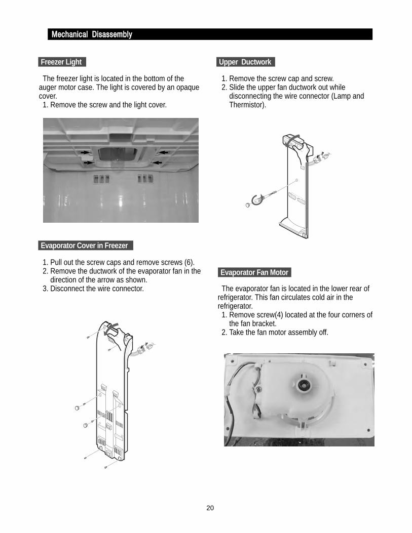
The freezer light is located in the bottom of theauger motor case. The light is covered by an opaquecover.
1. Remove the screw and the light cover.
1. Pull out the screw caps and remove screws (6).2. Remove the ductwork of the evaporator fan in the
direction of the arrow as shown.3. Disconnect the wire connector.
1. Remove the screw cap and screw.2. Slide the upper fan ductwork out while
disconnecting the wire connector (Lamp and Thermistor).
The evaporator fan is located in the lower rear ofrefrigerator. This fan circulates cold air in therefrigerator.
1. Remove screw(4) located at the four corners of the fan bracket.
2. Take the fan motor assembly off.
Upper Ductwork
Evaporator Fan Motor
Freezer Light
Evaporator Cover in Freezer
MMeecchhaanniiccaall DDiissaasssseemmbbllyy

21
Evaporator is located in the bottom of freezer toproduce cold air driven across the evaporator coils.
1. Take off the ductwork in Freezer.2. Disconnect the wire connector (Heater, Bimental,
and Thermistor).3. Desolder the inlet and outlet tubes.4. Remove the evaporator.5. Take the same steps to seal the system as
mentioned earlier.
The freezer thermistor is located at the top left offreezer vent. It sends temperature signals to themicro-processor.
The ambient thermistor is located inside the upperhinge cover. It sends temperature signals to themicro-processor.
The Ice-Maker thermistor is located in its bottom.The temperature signal sends the micro-processor.
Evaporator in Freezer
MMeecchhaanniiccaall DDiissaasssseemmbbllyy
Accumulator
Bimetal
Thermistor
ThermalFuse
Freezer Thermistor
Ambient Thermistor
Ice-MakerThermistor
Freezer Thermistor
AmbientThermistor
Thermistor(Ice-Maker)
22
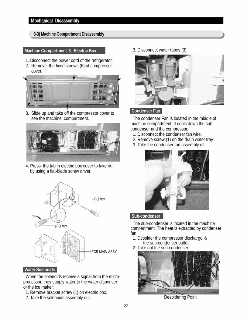
1. Disconnect the power cord of the refrigerator.2. Remove the fixed screws (6) of compressor
cover.
3. Slide up and take off the compressor cover to see the machine compartment.
4. Press the tab in electric box cover to take out by using a flat-blade screw driver.
When the solenoids receive a signal from the micro-processor, they supply water to the water dispenseror the ice maker.
1. Remove bracket screw (1) on electric box.2. Take the solenoids assembly out.
3. Disconnect water tubes (3).
The condenser Fan is located in the middle ofmachine compartment. It cools down the sub-condenser and the compressor.
1. Disconnect the condenser fan wire.2. Remove screw (1) on the drain water tray.3. Take the condenser fan assembly off.
The sub-condenser is located in the machinecompartment. The heat is extracted by condenserfan.
1. Desolder the compressor discharge &the sub-condenser outlet.
2. Take out the sub-condenser.
Machine Compartment && Electric Box
MMeecchhaanniiccaall DDiissaasssseemmbbllyy
8-3) Machine Compartment Disassembly
(+)driver
(-)driver
PCB-MAIN ASSY
Water Solenoids
Condenser Fan
Sub-condenser
Desoldering Point

23
9. Operation Function
9-1) Digital Panel ······································ 24
9-2) Temperature Control Function ···························· 24
9-3) Power Freeze and Power Cool Functions ····················· 25
9-4) Child Lock Function ·································· 25
9-5) Ice & Water Dispenser Function ·························· 26
9-6) C-Fan Motor Delay Function of the Machine Compartment ···········26
9-7) CoolSelect ZoneTM Function ····························· 26
9-8) Water Filter Indicator Function···························· 27
9-9) Ice-Maker Function ·································· 27
9-10) Defrost Function ··································· 29
9-11) Forced Operation Function (Pull-down/R-Defrost/R,F-Defrost/Cancellation) · 30
9-12) Sound Function ··································· 31
9-13) Exhibition Function ································· 31
9-14) Self-Diagnostics Function······························ 31
9-15) Load Operation Check Function ·························· 33
9-16) Restoration Function for Power Outage······················ 33
9-17) Set Point Shift Function ······························· 33
9-18) Table of Set Point Shift Function ·························· 34
24
9. Operation Function
9-1) Digital Panel
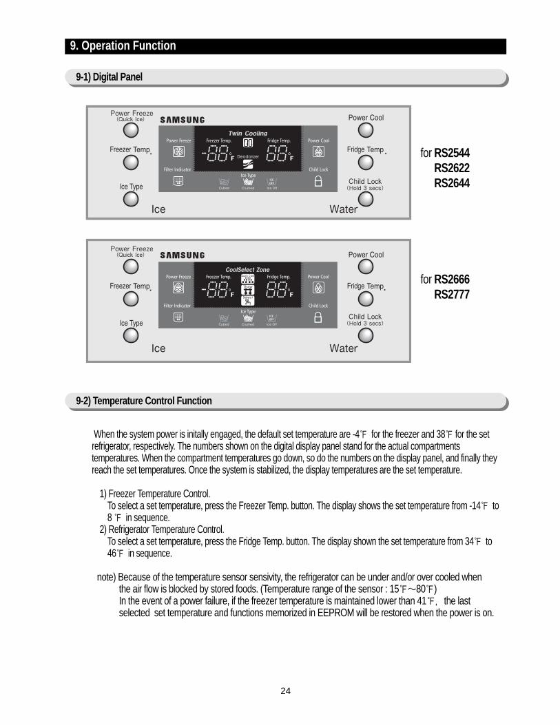
When the system power is initally engaged, the default set temperature are -4 for the freezer and 38 for the setrefrigerator, respectively. The numbers shown on the digital display panel stand for the actual compartmentstemperatures. When the compartment temperatures go down, so do the numbers on the display panel, and finally theyreach the set temperatures. Once the system is stabilized, the display temperatures are the set temperature.
1) Freezer Temperature Control.To select a set temperature, press the Freezer Temp. button. The display shows the set temperature from -14 to 8 in sequence.
2) Refrigerator Temperature Control.To select a set temperature, press the Fridge Temp. button. The display shown the set temperature from 34 to 46 in sequence.
note) Because of the temperature sensor sensivity, the refrigerator can be under and/or over cooled when the air flow is blocked by stored foods. (Temperature range of the sensor : 15∼80)In the event of a power failure, if the freezer temperature is maintained lower than 41, the last selected set temperature and functions memorized in EEPROM will be restored when the power is on.
for RS2544RS2622RS2644
for RS2666RS2777
9-2) Temperature Control Function
25
Operation Function
9-3) Quick Ice and Power Cool Functions
9-4) Child Lock Function
Select the Power Freezer(Quick Ice) or Power Cool button individually. These buttons are toggled ON & OFF as well as the indicators. Although you select these functions, the set temperature for the freezer & refrigerator are not changed. But, interior
temperature of both compartments will be controlled as mentioned below.
1) Power Freeze(Quick Ice) function1-1) When you press the Power Freeze(Quick Ice) button, the LED indicator will immediately light up. Please allow
10 second lag time to begin the actual operation. When this button is pressed again, the Power Freeze(QuickIce) function stops and the indicator will turn off.
1-2)If you select the Power Freezer(Quick Ice), interior temperature of the freezer will be controlled with -14 untilthe Ice bucket is filled up with ice cubes. When the Ice bucket is filled up with ice cubes, the freezer will return tooriginal set temperatures.Also, whenever the Ice bucket is released from being filled with ice cube, the freezer will repeat to perform thePower Freezer(Quick Ice) function.
Press the Power Freezer(Quick Ice) button twice to cancel the Power Freeze(Quick Ice)If you use this function, energy coconsumption will increase.Please turn off when not using this function.
1-3) The set temperature of the freezer will be retained as current settings during this function.1-4) When Power Freeze(Quick Ice) expires, the indicator goes off and the freezer set temperature will be restored.
2) Power Cool Function2-1) Power Cool operation and the indicator work exactly same as the Power Freeze function.2-2) When Power Cool is selected, Compressor and R-FAN operate continually until the refrigerator reaches 25.
This function will be terminated after 2 ½ hr running.
3) When you select Power Freeze and Power Cool togetherEach function works at the same time. The Compressor and F-FAN run continually and the R-FAN runs until the refrigerator reaches 25
4) Initial Power-On4-1) In the initial operation under the condition that the freezer and the refrigerator temperature is higher than 14
and 50 the Power Freeze is selected, the R-FAN will be turned off. or If Power Cool is selected, the F-FAN willbe turned off.
4-2) When both functions are selected, there is no benefit of fast cooling for each compartment.
When the child lock button is pressed for 3 seconds, the child lock indicator is on with an audible tone.-When it is locked, no function commands except the Ice type button will be accepted.-This function will prevent accidental setting that may be caused by children or pets.-To unlock the setting functions, press this button for 3 seconds again.
note) When the Power Freeze (Quick Ice) is selected, it enables maximum ice making output.The ice-making interval is reduced from 90 mins to 55 mins (55 mins will pass after supplying water, if the ice temperature is kept lower than 14 . the ice tray will be twisted).
26
Operation Function
9-5) Ice & Water Dispenser Function
9-6) C-Fan Motor Delay Function of the Machine Compartment
9-7) CoolSelect ZoneTM Function (RS2666,RS2777)
Among several ice-maker functions, the ice extraction function is performed by mechanical system. Only the relaycontrol for a cubed-ice dispensing and the SSR control for the ice chute door are performed electronically.
1) Select Cubed/Crushed/Ice-off function1-1) The Ice Type button selects Cubed/Crushed/Ice-off options in sequence.1-2) A default setting is Cubed option.1-3) If Cubed ice is selected, the Crushed ice bypass solenoid and the geared motor will allow Cubed ice to by pass
the ice Crusher.1-4) If Ice-off is selected, the ice maker will stop working. This option will be terminated when Cubed and Crushed
options are selected.
1-5) The ice chute door must be open for 5 seconds after dispensing ceases. After this 5 seconds delay, SSR will becontrolled to shut the ice chute door.
2) Water Dispenser function2-1) To dispense water, depress the water dispenser lever located in the dispenser recess.2-2) When the lever is depressed, the water solenoid valve located in the machine compartment is open to flow water.2-3) There is no electronic control function for this option.
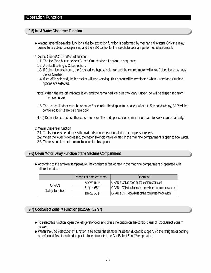
According to the ambient temperature, the condenser fan located in the machine compartment is operated withdifferent modes.
To select this function, open the refrigerator door and press the button on the control panel of CoolSelect Zone TM
drawer. When the CoolSelect ZoneTM function is selected, the damper inside fan ductwork is open. So the refrigerator cooling
is performed first, then the damper is closed to control the CoolSelect ZoneTM temperature.
Note) When the Ice-off indicator is on and the remained ice is in tray, only Cubed ice will be dispensed from the ice bucket.
Note) Do not force to close the ice chute door. Try to dispense some more ice again to work it automatically.
Ranges of ambient temp.Above 6661 ~ 65Below 60
C-FAN is ON as soon as the compressor is on.C-FAN is ON with 5 minutes delay from the compressor on.C-FAN is OFF regardless of the compressor operation.
C-FANDelay function
Operation
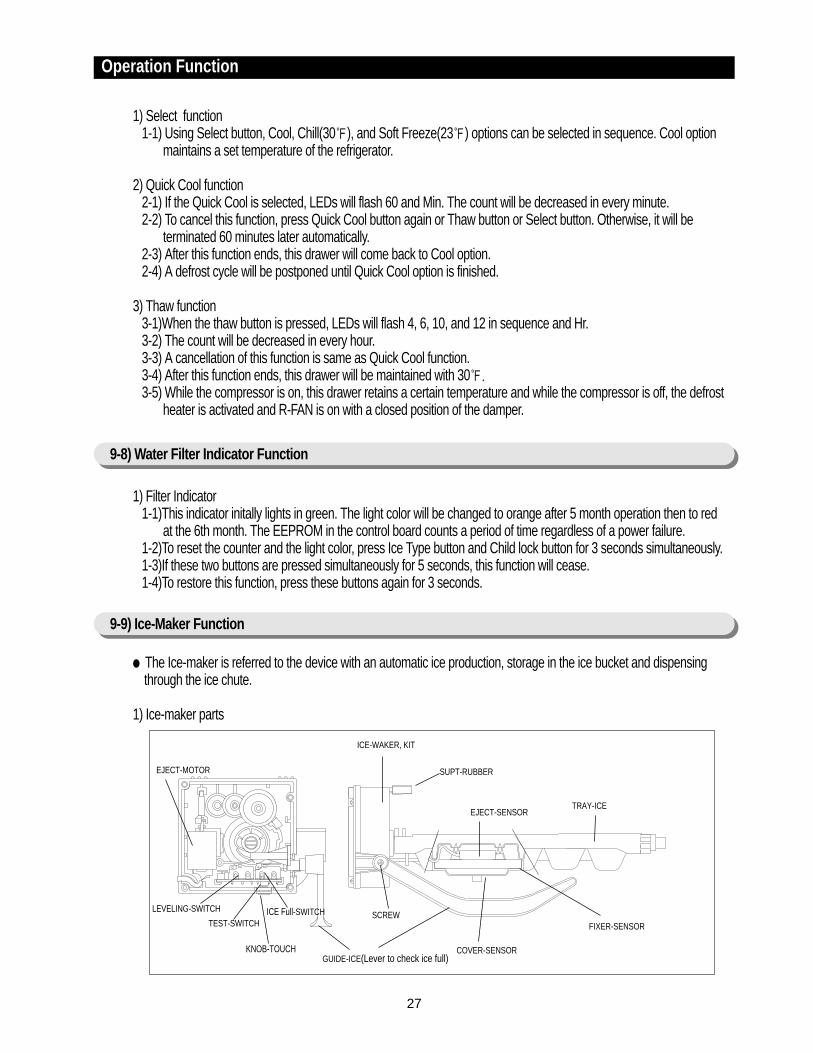
TRAY-ICEEJECT-SENSOR
COVER-SENSOR
SCREW
SUPT-RUBBER
FIXER-SENSOR
ICE-WAKER, KIT
EJECT-MOTOR
TEST-SWITCH
LEVELING-SWITCH
GUIDE-ICE(Lever to check ice full)KNOB-TOUCH
ICE Full-SWITCH
27
1) Select function1-1) Using Select button, Cool, Chill(30), and Soft Freeze(23) options can be selected in sequence. Cool option
maintains a set temperature of the refrigerator.
2) Quick Cool function2-1) If the Quick Cool is selected, LEDs will flash 60 and Min. The count will be decreased in every minute.2-2) To cancel this function, press Quick Cool button again or Thaw button or Select button. Otherwise, it will be
terminated 60 minutes later automatically.2-3) After this function ends, this drawer will come back to Cool option.2-4) A defrost cycle will be postponed until Quick Cool option is finished.
3) Thaw function3-1)When the thaw button is pressed, LEDs will flash 4, 6, 10, and 12 in sequence and Hr.3-2) The count will be decreased in every hour.3-3) A cancellation of this function is same as Quick Cool function.3-4) After this function ends, this drawer will be maintained with 30.3-5) While the compressor is on, this drawer retains a certain temperature and while the compressor is off, the defrost
heater is activated and R-FAN is on with a closed position of the damper.
1) Filter Indicator1-1)This indicator initally lights in green. The light color will be changed to orange after 5 month operation then to red
at the 6th month. The EEPROM in the control board counts a period of time regardless of a power failure.1-2)To reset the counter and the light color, press Ice Type button and Child lock button for 3 seconds simultaneously.1-3)If these two buttons are pressed simultaneously for 5 seconds, this function will cease.1-4)To restore this function, press these buttons again for 3 seconds.
The Ice-maker is referred to the device with an automatic ice production, storage in the ice bucket and dispensingthrough the ice chute.
1) Ice-maker parts
Operation Function
9-8) Water Filter Indicator Function
9-9) Ice-Maker Function
28
Operation Function
<Reference table>
Leveling S/WON(“LOW”)ON(“LOW”)
OFF(“HIGH”)
OFF(“HIGH”)
Ice full S/WON(“LOW”)
OFF(“HIGH”)ON(“LOW”)
OFF(“HIGH”)
Remark·MICOM Port
PIN #51: LevelingPIN #51: Ice full·Port level
OFF : 4.5V ↑ON : 0.5V ↓
JudgementNot readyNot ready
Not ready(Ice bucket with full of ice )
Ready
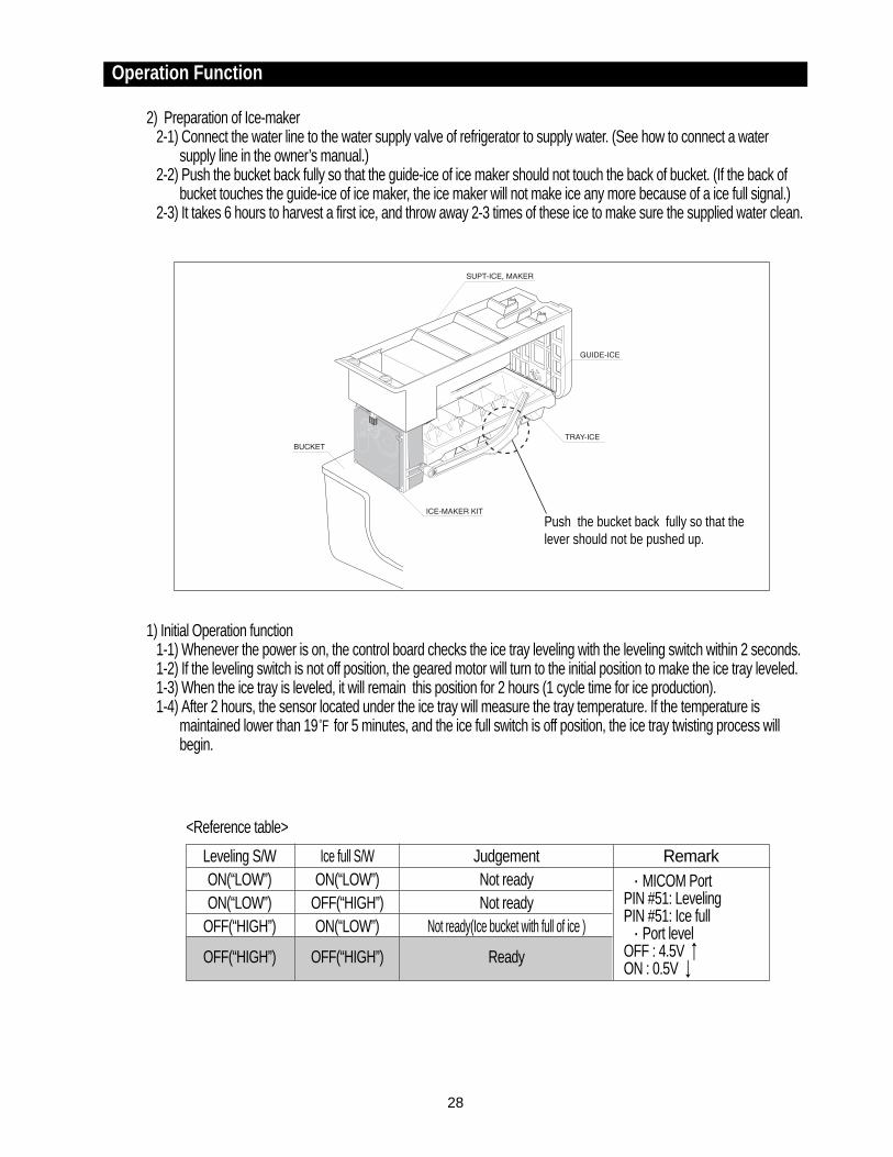
Push the bucket back fully so that thelever should not be pushed up.
2) Preparation of Ice-maker2-1) Connect the water line to the water supply valve of refrigerator to supply water. (See how to connect a water
supply line in the owner’s manual.)2-2) Push the bucket back fully so that the guide-ice of ice maker should not touch the back of bucket. (If the back of
bucket touches the guide-ice of ice maker, the ice maker will not make ice any more because of a ice full signal.)2-3) It takes 6 hours to harvest a first ice, and throw away 2-3 times of these ice to make sure the supplied water clean.
1) Initial Operation function1-1) Whenever the power is on, the control board checks the ice tray leveling with the leveling switch within 2 seconds.1-2) If the leveling switch is not off position, the geared motor will turn to the initial position to make the ice tray leveled.1-3) When the ice tray is leveled, it will remain this position for 2 hours (1 cycle time for ice production).1-4) After 2 hours, the sensor located under the ice tray will measure the tray temperature. If the temperature is
maintained lower than 19 for 5 minutes, and the ice full switch is off position, the ice tray twisting process willbegin.
29
Operation Function
2) Water Supply function2-1) When the ice tray is levelled again after ejecting ice, the water solenoid value will be controlled to supply water by
time check basis. (See the “Time to supply water” Table)
3) Ice production3-1) After 90 minutes pass from the water supply, the control board will check the temperature.3-2) If the sensor reads the temperature lower than 19 for more than 5 minutes, than the ice production process is
completed.
4) Test function In order to operate a test function, press the knob (Test Switch) for 1.5 second. This function can be used to check a proper working, to clean the ice tray, and to adjust the water level in the ice tray.4-1) This function only works when the ice tray is leveled and the ice full signal is cleared.4-2) When the water line is connected, each process such as a water supply, ejection, and leveling, can be investigated
by this button.
5) Ice off function5-1) When the Ice off option is selected by Ice Type button, the ice making process will cease.5-2) When the ice making process ceases, the final state will be the ice tray with supplied water.5-3) When Cubed or Crushed option is selected again, the control board will check an accummlated time period. After
making it 90 minutes and when the ice tray temperature is acceptable, ice ejection process will begin.
6) Functions when the freezer door is open When the freeze door is open, all ice maker related processes will cease in order to minimize noise and to prevent ice
from dispensing.6-1) The ice tray stops moving regardless of the position.6-2) The water supply process remains working as usual.6-3) If the ice tray is in the middle of ice ejecting process, close the freezer for 30 seconds and check if the tray is
leveled. If it is not leveled, it must be out of order.
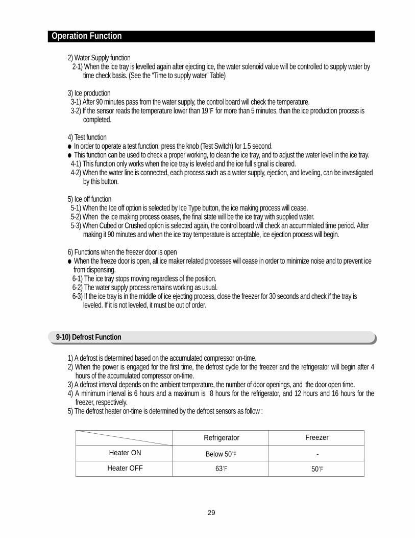
1) A defrost is determined based on the accumulated compressor on-time.2) When the power is engaged for the first time, the defrost cycle for the freezer and the refrigerator will begin after 4
hours of the accumulated compressor on-time.3) A defrost interval depends on the ambient temperature, the number of door openings, and the door open time.4) A minimum interval is 6 hours and a maximum is 8 hours for the refrigerator, and 12 hours and 16 hours for the
freezer, respectively.5) The defrost heater on-time is determined by the defrost sensors as follow :
9-10) Defrost Function
Freezer
Below 50
Refrigerator
63
Heater ON
Heater OFF
-
50
30
Operation Function
9-11) Forced Operation Function (Pull-down / R-Defrost / R.F-Defrost / Cancellation)
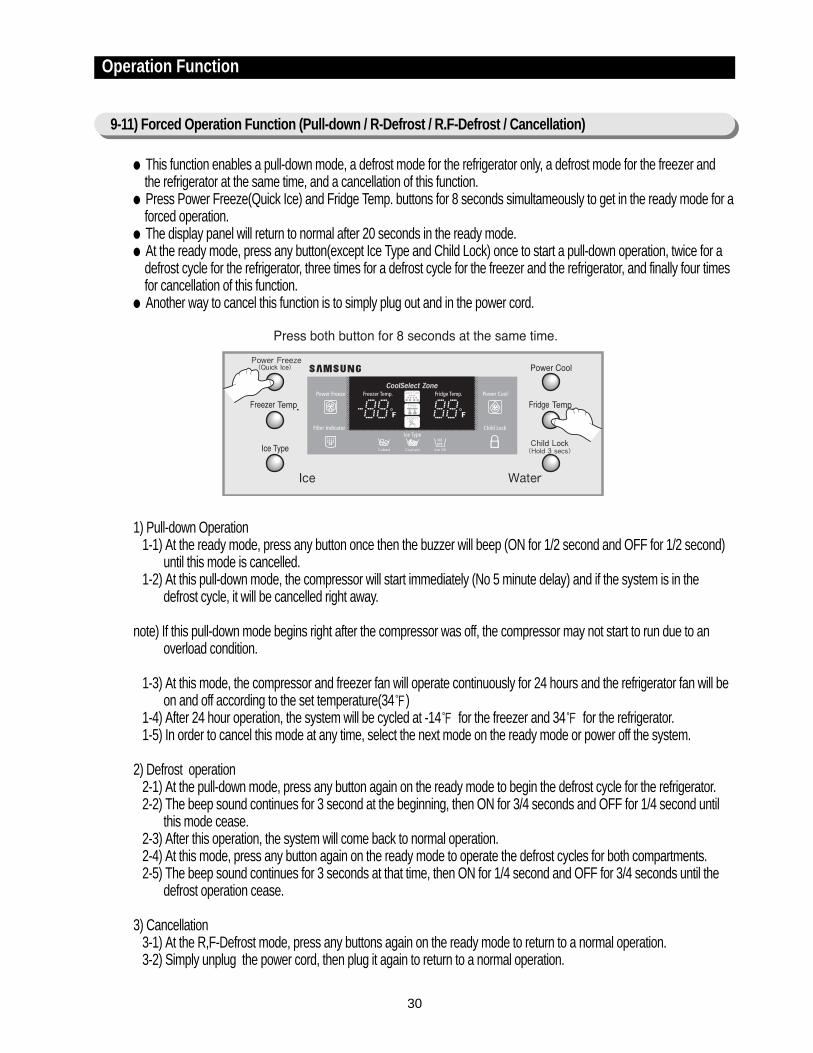
This function enables a pull-down mode, a defrost mode for the refrigerator only, a defrost mode for the freezer andthe refrigerator at the same time, and a cancellation of this function.
Press Power Freeze(Quick Ice) and Fridge Temp. buttons for 8 seconds simultameously to get in the ready mode for aforced operation.
The display panel will return to normal after 20 seconds in the ready mode. At the ready mode, press any button(except Ice Type and Child Lock) once to start a pull-down operation, twice for a
defrost cycle for the refrigerator, three times for a defrost cycle for the freezer and the refrigerator, and finally four timesfor cancellation of this function.
Another way to cancel this function is to simply plug out and in the power cord.
1) Pull-down Operation1-1) At the ready mode, press any button once then the buzzer will beep (ON for 1/2 second and OFF for 1/2 second)
until this mode is cancelled.1-2) At this pull-down mode, the compressor will start immediately (No 5 minute delay) and if the system is in the
defrost cycle, it will be cancelled right away.
note) If this pull-down mode begins right after the compressor was off, the compressor may not start to run due to anoverload condition.
1-3) At this mode, the compressor and freezer fan will operate continuously for 24 hours and the refrigerator fan will beon and off according to the set temperature(34)
1-4) After 24 hour operation, the system will be cycled at -14 for the freezer and 34 for the refrigerator.1-5) In order to cancel this mode at any time, select the next mode on the ready mode or power off the system.
2) Defrost operation2-1) At the pull-down mode, press any button again on the ready mode to begin the defrost cycle for the refrigerator.2-2) The beep sound continues for 3 second at the beginning, then ON for 3/4 seconds and OFF for 1/4 second until
this mode cease.2-3) After this operation, the system will come back to normal operation.2-4) At this mode, press any button again on the ready mode to operate the defrost cycles for both compartments.2-5) The beep sound continues for 3 seconds at that time, then ON for 1/4 second and OFF for 3/4 seconds until the
defrost operation cease.
3) Cancellation3-1) At the R,F-Defrost mode, press any buttons again on the ready mode to return to a normal operation.3-2) Simply unplug the power cord, then plug it again to return to a normal operation.
31
Operation Function
9-12) Sound Function
1) Sound function1-1) To make sure a command input, whenever a button is pressed, a “ding-dong” sounds.1-2) When two or more buttons are pressed simultaneously or if a wrong button is pressed, there is no sound.
2) Door Open Alarm2-1) When the doors remain open for 2 minutes, there are 10 times beeps.2-2) If the doors continue to remain open more than 2 minutes, the additional 10 beeps interval will change to 1 minute.2-3) The beeps will cease immediately when the doors are closed.
This function is for a display purpose on the floor of show room or store.
1) Mode ON/OFF1-1) For the exhibition mode, press Power Freeze and Freezer Temp. buttons simultaneously for 8 seconds until a
“ding-dong” sounds.1-2) Press the same time buttons again for 8 seconds to cancel this mode put with a “ding-dong” sound.
2) Operation2-1) Most of the system function except the compressor operation are working properly.2-2) There is no defrost cycle in this mode.
1) Self-Diagnostics in the initial Power ON1-1)The control board performs a self diagnostics test within 1 second and check out the temperature sensors abilities.1-2) If a sensor failure occurs, a corresponding LED segment will blink with a beep.1-3) When a LED segment blinks, only the cancellation function (Press Power Freeze and Power Cool buttons
simultaneously for 8 seconds) is acceptable.1-4) After a replacement of bad sensor or a cancellation of this function, this self diagnostics will end.
2) Self-Diagnostics in the normal operation2-1) To select this function, press Power Freeze and Power Cool buttons simultaneously for 8 seconds with an audible
tone.2-2) In the self diagnostic mode, only corresponding LED segments will be illuminated (see the check list on the next
page)2-3) After a 30 second illumination of error signal, the system will return to the normal operation.
9-13) Exhibition Function
9-14) Self-Diagnostics Function

32
Operation Function
Self-diagnostics check list
If any LEDs blink, the corresponding sensors andcomponents must be checked for an error.
NO ErrorICE-MAKER SENSORR-SENSORR-DEF-SENSORR-FAN ERRORI/M function errorCoolSelect ZoneTM SENSORR-DEFROST ERROREXIT-SENSORF-SENSORF-DEF ERRORF-FAN ERRORC-FAN ERRORF-DEFROST ERROR
①②③④⑤⑥⑦⑧⑨⑩⑪⑫⑬
Air sensor connector missing; contactfailure, electric wire cut, short-circuit;open air sensor itself failure; and so on
CoolSelectZoneTM sensor
R-DEFROSTERROR
Ambient AirSENSOR
Indicate Error when the temperature sensed byCoolSelect ZoneTM sensor is higher than 150 orlower than -58.
-
Indicate Error when the temperature sensed by theopen air sensor is higher than 150 or lower than -58.
FRE sensor connector missing; contactfailed, electric wire cut, short-circuit; F-Room sensor itself failure.
F-SENSOR Indicate Error when the temperature sensed by F-sensor is higher than 150 or lower than -58.
FRE evaporator defrosting sensorconnector missing; contact failed,electric wire cut, short-circuit; sensoritself failure; and so on
FRE DefrostSENSOR
Indicate Error when the temperature sensed by F-defrosting sensor is higher than 150 or lower than-58.
F-Fan motor operation failure; feedbacksignal line contact failure, motor’s electricwire missing; and so on.
F-FAN ERROR Indicate Error if the F and G signals generated bythe FAN-motor operation are not input.
C-Fan motor operation failure; feedbacksignal line contact failure, motor’s electricwire missing; and so on.
In the freezer room, if frost removal modeis finished due to limited time of 70minutes. Error is displayed
C-FAN ERROR(COMP-FAN)
Indicate Error if the F and G signals generated by theFAN-motor operation are not input
-F-DEFROST
ERROR
NO Error items LED Display Details Remarks
01
02
03
04
05
06
07
08
09
10
11
12
13
I/M-SENSORI/M sensor connector missing; contactfailure, electric wire cut, short-circuit; I/M-sensor failure; and so on
Indicate Error when the temperature sensed byI/M-sensor is higher than 150 or lower than–58.
R-SENSORREF sensor connector missing; contactfailure, electric wire cut, short- circuit; R-sensor itself failure; and so on
R-Fan motor operation failure; feedbacksignal line contact failed, electric wire cut,short- circuit; and so on
Indicate Error when the temperature sensed byR-sensor is higher than 150 or lower than–58.
Indicate Error when the temperature sensed by Rdefrosting sensor is higher than 150 or lower than–58.
REF DEFROSTSENSOR
REF evaporator internal defrosting sensorconnector missing; contact failure, electricwire cut, short-circuit; sensor itself failure;and so on
Indicate Error if the F and G signals generated by theFAN-motor operation are not input.
R-FAN ERROR
I/M functionERROR
Ice-ejector and level failed three timesor more
Error items of self-diagnostics
CoolSelect ZoneTM sensor connectormissing; contact failed, electric wire cut,short-circuit; CoolSelect ZoneTM sensor itselffailed; and so on.
In the refrigerator room, if frost removalmode is finished due to limited time of80 minutes. Error is displayed.
33
Operation Function
9-16) Restoration Function for Power Outage
9-17) Set Point Shift Function
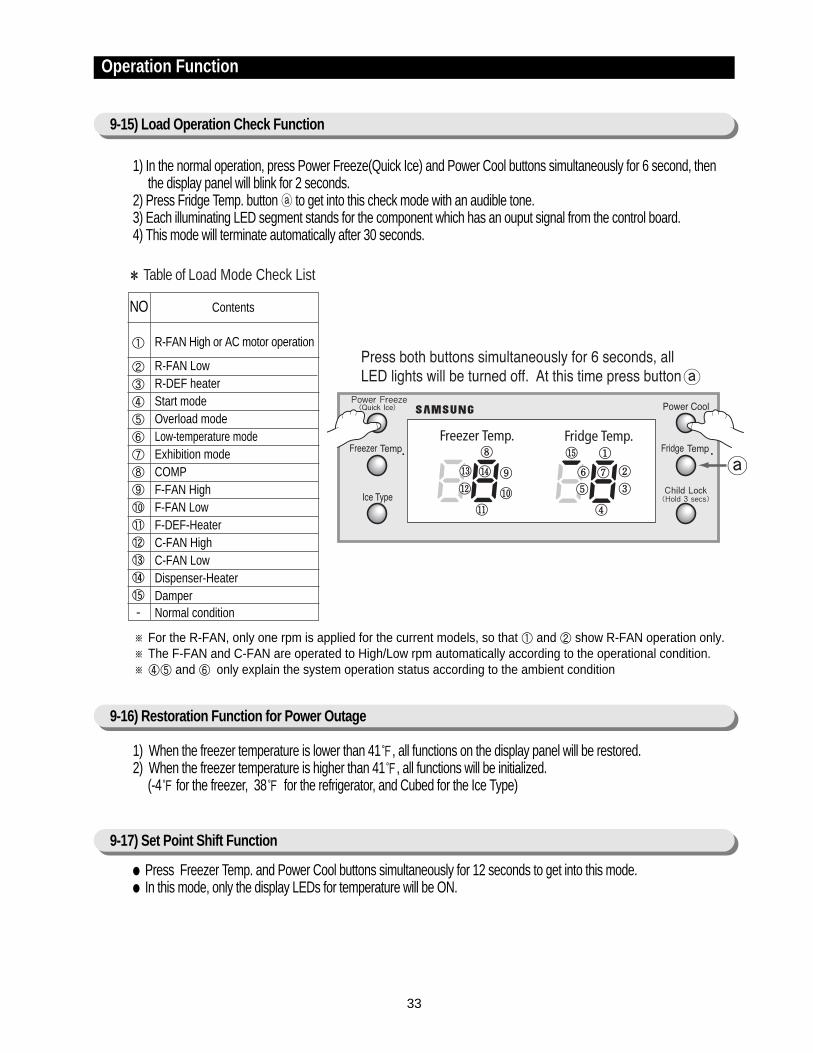
※ For the R-FAN, only one rpm is applied for the current models, so that ① and ② show R-FAN operation only.※ The F-FAN and C-FAN are operated to High/Low rpm automatically according to the operational condition.※ ④⑤ and ⑥ only explain the system operation status according to the ambient condition
1) When the freezer temperature is lower than 41, all functions on the display panel will be restored.2) When the freezer temperature is higher than 41, all functions will be initialized.
(-4 for the freezer, 38 for the refrigerator, and Cubed for the Ice Type)
Press Freezer Temp. and Power Cool buttons simultaneously for 12 seconds to get into this mode. In this mode, only the display LEDs for temperature will be ON.
NO Contents
R-FAN High or AC motor operation
R-FAN LowR-DEF heaterStart modeOverload modeLow-temperature modeExhibition modeCOMPF-FAN HighF-FAN LowF-DEF-HeaterC-FAN HighC-FAN LowDispenser-HeaterDamperNormal condition
Table of Load Mode Check List
①
②③④⑤⑥⑦⑧⑨⑩⑪⑫⑬⑭⑮-
9-15) Load Operation Check Function
1) In the normal operation, press Power Freeze(Quick Ice) and Power Cool buttons simultaneously for 6 second, thenthe display panel will blink for 2 seconds.
2) Press Fridge Temp. button to get into this check mode with an audible tone.3) Each illuminating LED segment stands for the component which has an ouput signal from the control board.4) This mode will terminate automatically after 30 seconds.
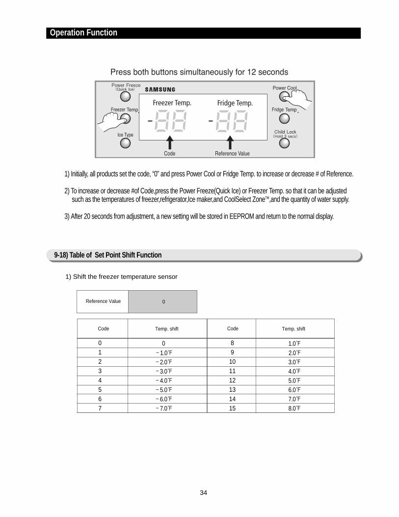
1) Shift the freezer temperature sensor
Code
01234567
0-1.0-2.0-3.0-4.0-5.0-6.0-7.0
1.0
2.0
3.0
4.0
5.0
6.0
7.0
8.0
Temp. shift Code Temp. shift
89
101112131415
9-18) Table of Set Point Shift Function
34
Operation Function
1) Initially, all products set the code, “0” and press Power Cool or Fridge Temp. to increase or decrease # of Reference.
2) To increase or decrease #of Code,press the Power Freeze(Quick Ice) or Freezer Temp. so that it can be adjusted such as the temperatures of freezer,refrigerator,Ice maker,and CoolSelect ZoneTM,and the quantity of water supply.
3) After 20 seconds from adjustment, a new setting will be stored in EEPROM and return to the normal display.
0Reference Value

35
Example) If you are lowering the current temperature of the freezer by -6.0
Code
01234567
89
101112131415
Temp. shift Code Temp. shift
2) Shift the refrigerator temperature sensor
0-1.0-2.0-3.0-4.0-5.0-6.0-7.0
1.0
2.0
3.0
4.0
5.0
6.0
7.0
8.0
Operation Function
Example) If you are raising the current temperature of the refrigerator by +3.0
1Reference Value

36
Operation Function
5) Shift the CoolSelect ZoneTM temperature sensor.
The following options is limited to a model with the Ice Maker.
3) Adjust the time to supply water for the icemaker
4) Shift the Ice maker temperature sensor
3Reference Value
0
Code Time to supply water
5 sec
1 4 sec
2 3 sec
3 6 sec
4 7 sec
5 8 sec
6 9 sec
7
8
9
10
11
12
13
14
15
10 sec
12 sec
13 sec
15 sec
17 sec
19 sec
21 sec
23 sec
25 sec
0
Code Ice makertemperature sensor
14
1 12
2 10.5
3 8.5
4 16
5 17
6 19
7 21
0
Code CoolSelect ZoneTM
temperature sensor
0
1 -1.0
2 -2.0
3 -3.0
4 1.0
5 2.0
6 3.0
7 4.0
4Reference Value
20Reference Value
37
10. Circuit Descriptions
10-1) Source Power Circuit ································ 38
10-2) Oscillator Circuit ··································· 38
10-3) Reset Circuit ····································· 38
10-4) Door S/W Sensing Circuit······························ 39
10-5) Temperature Sensing Circuit ···························· 39
10-6) Key Scan and Display Circuit···························· 40
10-7) CoolSelect ZoneTM Panel Circuit ·························· 42
10-8) Fan Motor(BLDC) Drive Circuit··························· 43
10-9) EEPROM Circuit ··································· 44
10-10) Option Circuit ···································· 44
10-11) Load Drive Circuit·································· 44
38
Circuit Descriptions
10-1) Source Power Circuit
10-2) Oscillator Circuit
10-3) Reset Circuit
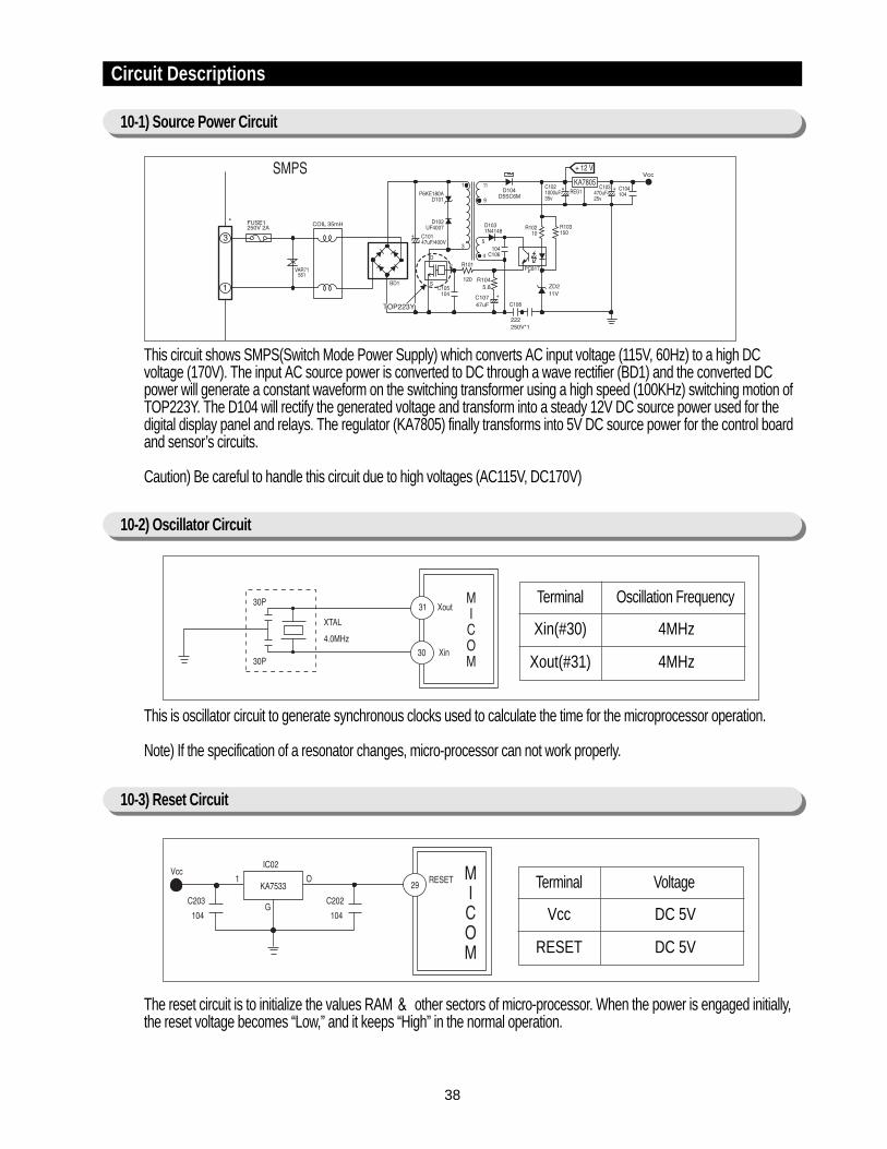
Terminal Oscillation Frequency
Xin(#30)
Xout(#31)
4MHz
4MHz
This circuit shows SMPS(Switch Mode Power Supply) which converts AC input voltage (115V, 60Hz) to a high DCvoltage (170V). The input AC source power is converted to DC through a wave rectifier (BD1) and the converted DCpower will generate a constant waveform on the switching transformer using a high speed (100KHz) switching motion ofTOP223Y. The D104 will rectify the generated voltage and transform into a steady 12V DC source power used for thedigital display panel and relays. The regulator (KA7805) finally transforms into 5V DC source power for the control boardand sensor’s circuits.
Caution) Be careful to handle this circuit due to high voltages (AC115V, DC170V)
This is oscillator circuit to generate synchronous clocks used to calculate the time for the microprocessor operation.
Note) If the specification of a resonator changes, micro-processor can not work properly.
The reset circuit is to initialize the values RAM & other sectors of micro-processor. When the power is engaged initially,the reset voltage becomes “Low,” and it keeps “High” in the normal operation.
Terminal Voltage
Vcc
RESET
DC 5V
DC 5V
39
Circuit Descriptions
10-4) Door S/W Sensing Circuit
10-5) Temperature Sensing Circuit
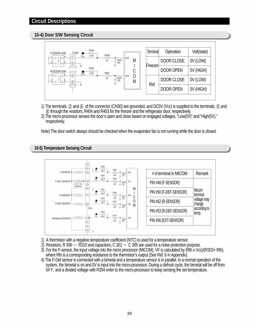
1) The terminals, ② and ⑥ of the connector (CN30) are grounded, and DC5V (Vcc) is supplied to the terminals, ⑤ and⑥ through the resistors, R404 and R403 for the freezer and the refrigerator door, respectively.
2) The micro-processor senses the door’s open and close based on engaged voltages, “Low(0V)” and “High(5V),”respectively.
Note) The door switch always should be checked when the evaporator fan is not running while the door is closed.
Terminal Operation Volt(state)
FreezerDOOR CLOSE
DOOR OPEN
0V (LOW)
5V (HIGH)
Ref.DOOR CLOSE
DOOR OPEN
0V (LOW)
5V (HIGH)
# of terminal in MICOM Remark
PIN #49 (F-SENSOR)
PIN #50 (F-DEF-SENSOR)
PIN #52 (R-SENSOR)
PIN #53 (R-DEF-SENSOR)
PIN #56 (EXT-SENSOR)
Micomterminalvoltage maychangeaccording totemp.
1) A thermistor with a negative temperature coefficient (NTC) is used for a temperature sensor.2) Resistors, R 306 ∼ R310 and capacitors, C 301 ∼ C 305 are used for a noise protection purpose.3) For the F-sensor, the input voltage into the micro processor (MICOM), VF is calculated by (Rth x Vcc)/(R303+ Rth),
where Rth is a corresponding resistance to the thermistor’s output (See Ref. 6 in Appendix).4) The F-Def sensor is connected with a bimetal and a temperature sensor is in parallel. In a normal operation of the
system, the bimetal is on and 0V is input into the micro-processor. During a defrost cycle, the bimetal will be off from54, and a divided voltage with R304 enter to the micro-processor to keep sensing the set temperature.
40
Circuit Descriptions
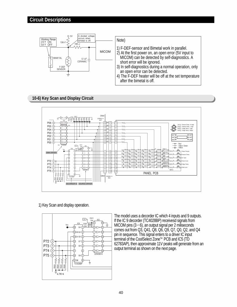
10-6) Key Scan and Display Circuit
Power Freeze
Freezer Temp.
Ice Type
Power Cool
Fridge Temp.
Child Lock
Note)
1) F-DEF-sensor and Bimetal work in parallel.2) At the first power on, an open error (5V input to
MICOM) can be detected by self-diagnostics. Ashort error will be ignored.
3) In self-diagnostics during a normal operation, onlyan open error can be detected.
4) The F-DEF heater will be off at the set temperatureafter the bimetal is off.
1) Key Scan and display operation.
The model uses a decorder IC which 4 inputs and 9 outputs.If the IC 9 decorder (TC4028BP) receivesd signals fromMICOM pins (3∼6), an output signal per 2 milisecondscomes out from Q3, Q41, Q8, Q6, Q9, Q7, Q0, Q2, and Q4pin in sequence. This signal enters to a driver IC inputterminal of the CoolSelect ZoneTM PCB and IC5 (TD62783AP), then approximate 11V peaks will generate from anoutput terminal as shown on the next page.
41
Circuit Descriptions
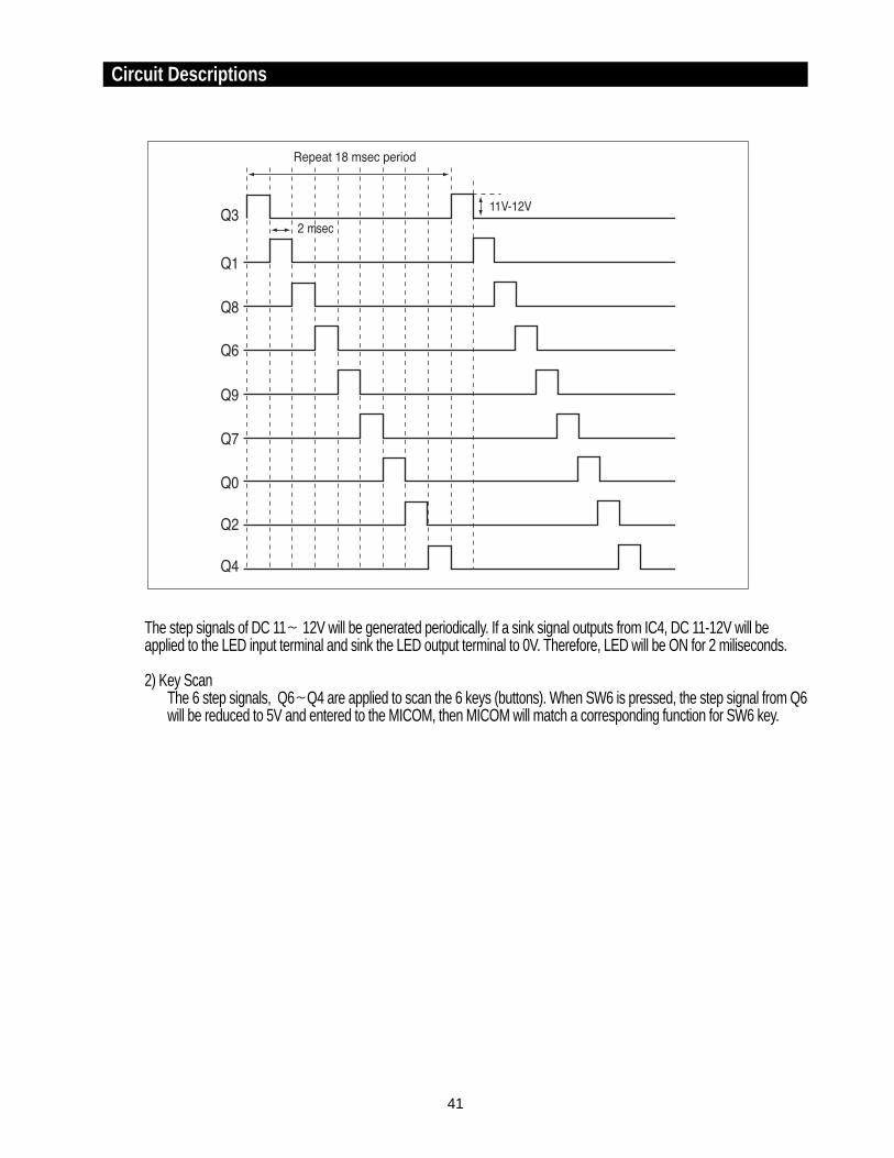
The step signals of DC 11∼ 12V will be generated periodically. If a sink signal outputs from IC4, DC 11-12V will beapplied to the LED input terminal and sink the LED output terminal to 0V. Therefore, LED will be ON for 2 miliseconds.
2) Key ScanThe 6 step signals, Q6∼Q4 are applied to scan the 6 keys (buttons). When SW6 is pressed, the step signal from Q6will be reduced to 5V and entered to the MICOM, then MICOM will match a corresponding function for SW6 key.
42
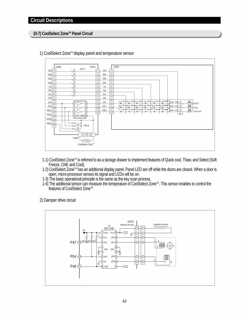
1) CoolSelect ZoneTM display panel and temperature sensor
1-1) CoolSelect ZoneTM is referred to as a storage drawer to implement features of Quick cool, Thaw, and Select (SoftFreeze, Chill, and Cool).
1-2) CoolSelect ZoneTM has an additional display panel. Panel LED are off while the doors are closed. When a door isopen, micro-processor senses its signal and LEDs will be on.
1-3) The basic operational principle is the same as the key scan process.1-4) The additional sensor can measure the temperature of CoolSelect ZoneTM. This sensor enables to control the
features of CoolSelect ZoneTM.
2) Damper drive circuit
Circuit Descriptions
10-7) CoolSelect ZoneTM Panel Circuit
43
Circuit Descriptions
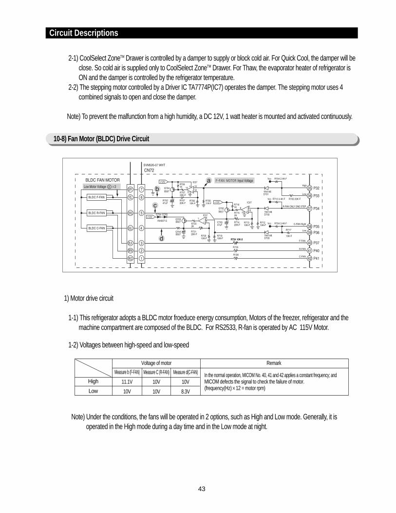
10-8) Fan Motor (BLDC) Drive Circuit
2-1) CoolSelect ZoneTM Drawer is controlled by a damper to supply or block cold air. For Quick Cool, the damper will beclose. So cold air is supplied only to CoolSelect ZoneTM Drawer. For Thaw, the evaporator heater of refrigerator isON and the damper is controlled by the refrigerator temperature.
2-2) The stepping motor controlled by a Driver IC TA7774P(IC7) operates the damper. The stepping motor uses 4combined signals to open and close the damper.
Note) To prevent the malfunction from a high humidity, a DC 12V, 1 watt heater is mounted and activated continuously.
1) Motor drive circuit
1-1) This refrigerator adopts a BLDC motor froeduce energy consumption, Motors of the freezer, refrigerator and themachine compartment are composed of the BLDC. For RS2533, R-fan is operated by AC 115V Motor.
1-2) Voltages between high-speed and low-speed
Note) Under the conditions, the fans will be operated in 2 options, such as High and Low mode. Generally, it isoperated in the High mode during a day time and in the Low mode at night.
Voltage of motor
High
Low
Measure b (F-FAN)
11.1V
10V
Measure C (R-FAN)
10V
10V
Measure d(C-FAN)
10V
8.3V
In the normal operation, MICOM No. 40, 41 and 42 applies a constant frequency; andMICOM defects the signal to check the failure of motor.(frequency(Hz)×12 = motor rpm)
Remark
44
Circuit Descriptions
10-10) Option Circuit
10-11) Load Drive Circuit
10-9) EEPROM Circuit
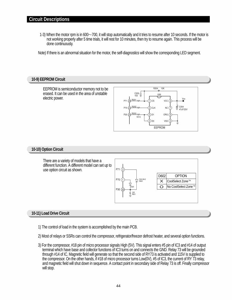
EEPROM is semiconductor memory not to beerased. It can be used in the area of unstableelectric power.
1-3) When the motor rpm is in 600∼700, it will stop automatically and it tries to resume after 10 seconds. If the motor isnot working properly after 5 time trials, it will rest for 10 minutes, then try to resume again. This process will bedone continuously.
Note) If there is an abnormal situation for the motor, the self-diagnostics will show the corresponding LED segment.
1) The control of load in the system is accomplished by the main PCB.
2) Most of relays or SSRs can control the compressor, refrigerator/freezer defrost heater, and several option functions.
3) For the compressor, #18 pin of micro processor signals High (5V). This signal enters #5 pin of IC3 and #14 of outputterminal which have base and collector functions of IC3 turns on and connects the GND. Relay 73 will be groundedthrough #14 of IC. Magnetic field will generate so that the second side of RY73 is activated and 115V is supplied tothe compressor. On the other hands, if #18 of micro processor turns Low(0V), #5 of IC3, the current of RY 73 relay,and magnetic field will shut down in sequence. A contact point in secondary side of Relay 73 is off. Finally compressorwill stop.
There are a variety of models that have adifferent function. A different model can set up touse option circuit as shown.
X
O
D602 OPTION CoolSelect ZoneTM
No CoolSelect ZoneTM

45
Circuit Descriptions
4) The principles of other loads is the same as 3) item described.
Note) SSR(Solid State Relay) is a kind of Relay.
*COMP. equivalence circuit of drive section
ICE-WATER SOLENOID(ICE-WATER SOL)
(AUGER MOTOR)AUGER MOTOR
46
Check the exchange of fuse anddisconnection cause.
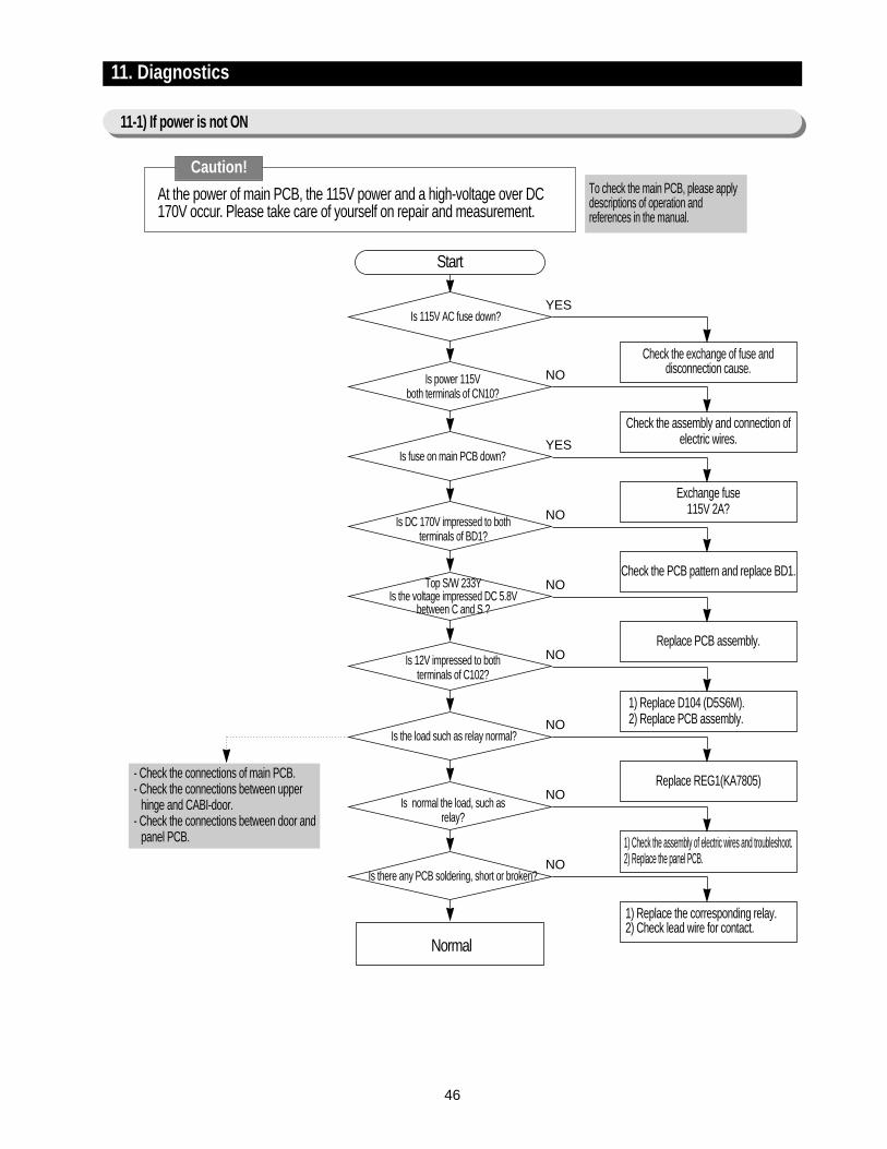
- Check the connections of main PCB.- Check the connections between upper
hinge and CABI-door.- Check the connections between door and
panel PCB.
11. Diagnostics
11-1) If power is not ON
At the power of main PCB, the 115V power and a high-voltage over DC170V occur. Please take care of yourself on repair and measurement.
Is 115V AC fuse down?
Is power 115V both terminals of CN10?
Is fuse on main PCB down?
Is DC 170V impressed to both terminals of BD1?
Top S/W 233YIs the voltage impressed DC 5.8V
between C and S ?
Is 12V impressed to both terminals of C102?
Is the load such as relay normal?
Is normal the load, such as relay?
Is there any PCB soldering, short or broken?
Normal
Start
To check the main PCB, please applydescriptions of operation andreferences in the manual.
YES
Check the assembly and connection ofelectric wires.
NO
Exchange fuse115V 2A?
YES
Check the PCB pattern and replace BD1.
NO
Replace PCB assembly.
NO
1) Replace D104 (D5S6M).2) Replace PCB assembly.
NO
Replace REG1(KA7805)
NO
1) Check the assembly of electric wires and troubleshoot.2) Replace the panel PCB.
NO
1) Replace the corresponding relay.2) Check lead wire for contact.
NO
Caution!
47
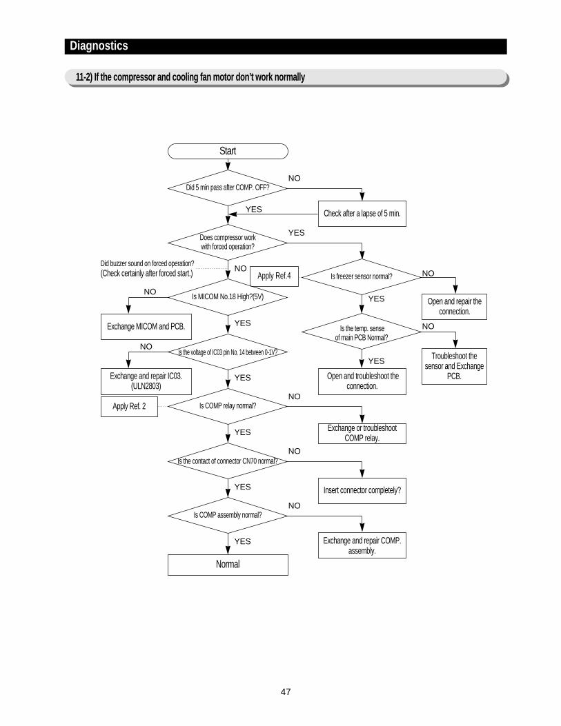
Diagnostics
11-2) If the compressor and cooling fan motor don’t work normally
Apply Ref.4
Did 5 min pass after COMP. OFF?
Start
Check after a lapse of 5 min.
Did buzzer sound on forced operation?(Check certainly after forced start.)
Exchange MICOM and PCB.
Exchange and repair IC03.(ULN2803)
Does compressor work with forced operation?
Is MICOM No.18 High?(5V) Open and repair theconnection.
Troubleshoot thesensor and Exchange
PCB.
Is the voltage of IC03 pin No. 14 between 0-1V?
Open and troubleshoot theconnection.
Is COMP relay normal?
Exchange or troubleshootCOMP relay.
Apply Ref. 2
Is the contact of connector CN70 normal?
Insert connector completely?
Is COMP assembly normal?
Exchange and repair COMP.assembly.
Normal
NO
YES
YES
NO
NO
NO
NO
YES NO
YES
YES
YES
NO
YES
NO
YES
NO
YES
Is freezer sensor normal?
Is the temp. sense of main PCB Normal?
48
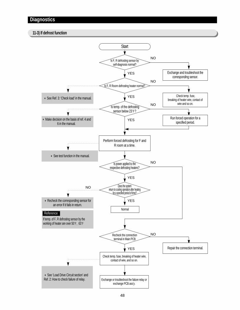
Diagnostics
11-3) If defrost function
Is F, R defrosting sensor by self-diagnosis normal?
Start
Exchange and troubleshoot thecorresponding sensor.
See Ref. 3: ‘Check load’ in the manual.
Make decision on the basis of ref. 4 and6 in the manual.
See test function in the manual.
Recheck the corresponding sensor for an error if it fails in return.
See ‘Load Drive Circuit section’ andRef. 2: How to check failure of relay.
Is F, R Room defrosting heater normal?
Check temp. fuse, breaking of heater wire, contact of
wire and so on.Is temp. of the defrosting
sensor below 23?
Run forced operation for a specified period.
Repair the connection terminal.
Perform forced defrosting for F and R room at a time.
Normal
Check temp. fuse, breaking of heater wire,contact of wire, and so on.
Exchange or troubleshoot the failure relay orexchange PCB ass’y.
Is power applied to the respective defrosting heaters?
Does the system return to cooling operation after heating
for a specified period of time?
Recheck the connection terminal in Main PCB
NO
NO
YES
YES
NO
YES
NO
NO
NO
YES
YES
YES
If temp. of F, R defrosting sensor by theworking of heater are over 50, 63
Reference

49
Diagnostics
11-4) If there is a trouble with self-diagnosis
1) If the ambient sensor has trouble
No trouble with PCB and temperature sensor.Recheck the contact failure of connector.
YES
YES
YES
2) If the temperature sensor of F and R room has trouble
See Ref. 4 (descriptions ofcircuit operation, and howto check temperaturesensor in the manual.)
- Error of sensor can be seen on the front display of refrigerator. If power is impressed to refrigerator first, an failure of sensor is found. The refrigeratorwill stop working and display(blink) the region of trouble-occurred sensor repetitively.
- Even if sensor has failure during the operation, the refrigerator will not stop working but can run the normal cooling operation because of being operatedin the Emergency Operation mode. Therefore you’ re requested to use how to check self-diagnosis(at page 31) in the manual.
A bad contact or connector missing?
Was the Main – PCB connector(CN31) inserted
correctly?
Is the ambient temperature sensor normal?
Is the input of voltage to MICOM pin No. 63 normal?
Start
NO
Exchange the temperature sensor.
NO
Check the iced solder and short of main-PCB.
NO
YES
YES
YES
YES
See Ref.4 (descriptions ofcircuit operation, and howto check temperaturesensor in the manual.)
For sensor resistance pertemperature, make use ofthe resistance values fromRef. 4 and 5.
Exchange the temperature sensor.
Is the unit of Fridge’s temperature
sensor normal?
Was the Main – PCB connector(CN30) inserted
correctly?
Is the sequence of insertion of connector(CN30) wire identical to
the circuit diagram?
Is the input voltage to MICOM pin No. 59 normal?
Start
NO
Troubleshoot a bad contact or missing ofconnector.
NO
Check if the iced solder of main PCB isshort.
NO
Modify the wrong configuration of connectorwire -in case of being not inserted orincorrectly inserted - to be coincided with thecircuit diagram.
NO
No trouble with PCB and temperature sensor.Recheck the connector for an error of contact.
50
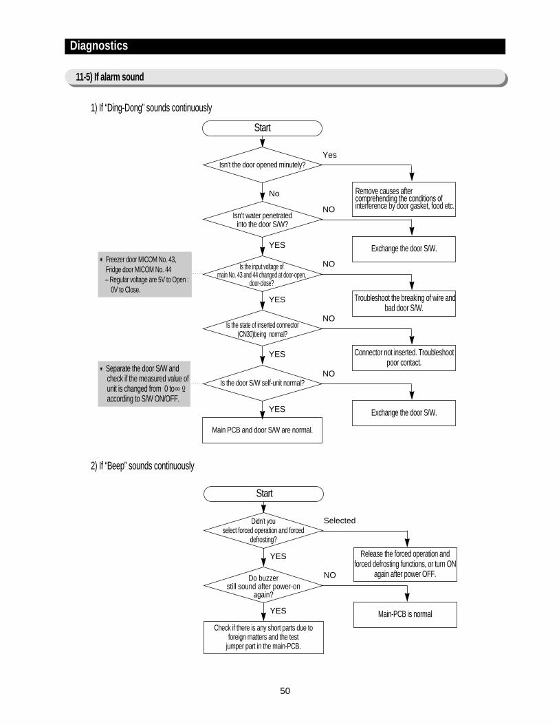
Freezer door MICOM No. 43,Fridge door MICOM No. 44 – Regular voltage are 5V to Open :
0V to Close.
Separate the door S/W andcheck if the measured value ofunit is changed from 0 to∞Ωaccording to S/W ON/OFF.
1) If “Ding-Dong” sounds continuously
Isn’t the door opened minutely?
Start
Remove causes aftercomprehending the conditions ofinterference by door gasket, food etc.
Isn’t water penetrated into the door S/W?
Exchange the door S/W.
Is the input voltage of main No. 43 and 44 changed at door-open,
door-close?
Troubleshoot the breaking of wire andbad door S/W.
Main PCB and door S/W are normal.
Yes
NO
No
YES
NO
Connector not inserted. Troubleshootpoor contact.
NO
Exchange the door S/W.
NO
YES
Is the state of inserted connector(CN30)being normal?
YES
Is the door S/W self-unit normal?
YES
2) If “Beep” sounds continuously
Didn’t you select forced operation and forced
defrosting?
Start
Release the forced operation andforced defrosting functions, or turn ON
again after power OFF.Do buzzer still sound after power-on
again?
Main-PCB is normal
Check if there is any short parts due to foreign matters and the test
jumper part in the main-PCB.
Selected
NO
YES
YES
Diagnostics
11-5) If alarm sound
51
Diagnostics
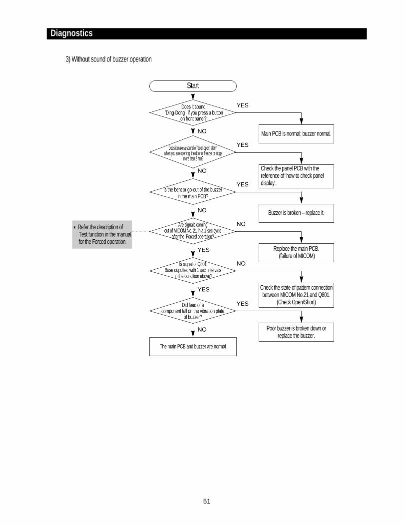
3) Without sound of buzzer operation
Does it sound‘Ding-Dong’if you press a button
on front panel?
Start
Main PCB is normal; buzzer normal.
Check the panel PCB with thereference of ‘how to check paneldisplay’.
Buzzer is broken – replace it.
Does it make a sound of ‘door-open’ alarmwhen you are opening the door of freezer or fridge
more than 2 min?
Is the bent or go-out of the buzzerin the main PCB?
The main PCB and buzzer are normal
YES
YES
NO
NO
YES
NO
NO
Replace the main PCB.(failure of MICOM)
Are signals coming out of MICOM No. 21 in a 1-sec cycle
after the Forced operation?
Is signal of Q801 Base ouputted with 1 sec. intervals
in the condition above?
Did lead of a component fall on the vibration plate
of buzzer?
NO
Check the state of pattern connectionbetween MICOM No.21 and Q801.
(Check Open/Short)
NO
Poor buzzer is broken down orreplace the buzzer.
YES
YES
YES
Refer the description ofTest function in the manualfor the Forced operation.
52
Diagnostics
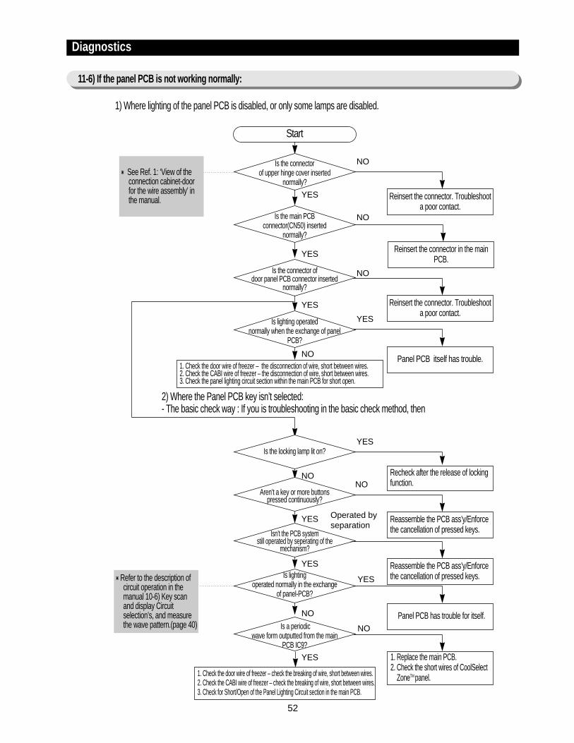
11-6) If the panel PCB is not working normally:
1) Where lighting of the panel PCB is disabled, or only some lamps are disabled.
2) Where the Panel PCB key isn’t selected:- The basic check way : If you is troubleshooting in the basic check method, then
Is the connector of upper hinge cover inserted
normally?
Start
Reinsert the connector. Troubleshoota poor contact.
Is the main PCB connector(CN50) inserted
normally?
Reinsert the connector in the mainPCB.
Is the connector of door panel PCB connector inserted
normally?
Reinsert the connector. Troubleshoota poor contact.
1. Check the door wire of freezer – the disconnection of wire, short between wires.2. Check the CABI wire of freezer – the disconnection of wire, short between wires.3. Check the panel lighting circuit section within the main PCB for short open.
1. Check the door wire of freezer – check the breaking of wire, short between wires.2. Check the CABI wire of freezer – check the breaking of wire, short between wires.3. Check for Short/Open of the Panel Lighting Circuit section in the main PCB.
NO
NO
YES
YES
NO
Panel PCB itself has trouble.
YES
YES
Is lighting operated normally when the exchange of panel
PCB?
NO
NO Recheck after the release of lockingfunction.
YESIs the locking lamp lit on?
YES Reassemble the PCB ass’y/Enforcethe cancellation of pressed keys.
NOAren’t a key or more buttons
pressed continuously?
YES Reassemble the PCB ass’y/Enforcethe cancellation of pressed keys.
Operated byseparation
Isn’t the PCB system still operated by seperating of the
mechanism?
NO Panel PCB has trouble for itself.
YESIs lighting operated normally in the exchange
of panel-PCB?
YES 1. Replace the main PCB.2. Check the short wires of CoolSelect
ZoneTM panel.
NOIs a periodic wave form outputted from the main
PCB IC9?
See Ref. 1: ‘View of theconnection cabinet-doorfor the wire assembly’ inthe manual.
Refer to the description ofcircuit operation in themanual 10-6) Key scanand display Circuitselection’s, and measurethe wave pattern.(page 40)
53
Diagnostics
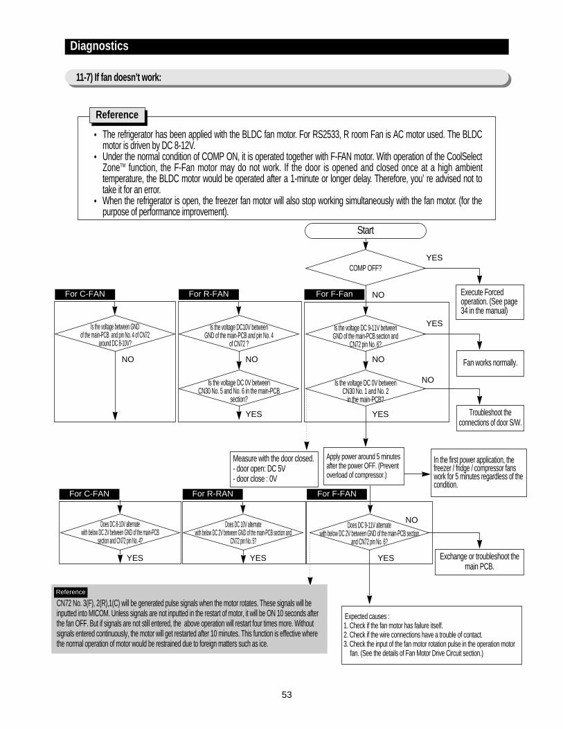
11-7) If fan doesn’t work:
The refrigerator has been applied with the BLDC fan motor. For RS2533, R room Fan is AC motor used. The BLDCmotor is driven by DC 8-12V.Under the normal condition of COMP ON, it is operated together with F-FAN motor. With operation of the CoolSelectZoneTM function, the F-Fan motor may do not work. If the door is opened and closed once at a high ambienttemperature, the BLDC motor would be operated after a 1-minute or longer delay. Therefore, you’ re advised not totake it for an error.When the refrigerator is open, the freezer fan motor will also stop working simultaneously with the fan motor. (for thepurpose of performance improvement).
Reference
COMP OFF?
Start
Execute Forced operation. (See page 34 in the manual)
Is the voltage DC 9-11V between GND of the main-PCB section and
CN72 pin No. 6?
Fan works normally.
Is the voltage DC 0V between CN30 No. 1 and No. 2
in the main-PCB?
Troubleshoot theconnections of door S/W.
In the first power application, thefreezer / fridge / compressor fanswork for 5 minutes regardless of thecondition.
Apply power around 5 minutesafter the power OFF. (Preventoverload of compressor.)
Expected causes :1. Check if the fan motor has failure itself.2. Check if the wire connections have a trouble of contact.3. Check the input of the fan motor rotation pulse in the operation motor
fan. (See the details of Fan Motor Drive Circuit section.)
YES
YES
NO
NO
NO
YES
Is the voltage DC10V between GND of the main-PCB and pin No. 4
of CN72 ?
Is the voltage DC 0V between CN30 No. 5 and No. 6 in the main-PCB
section?
NO
Is the voltage between GND of the main-PCB and pin No. 4 of CN72
around DC 8-10V?
NO
YES
Does DC 9-11V alternate with below DC 2V between GND of the main-PCB section
and CN72 pin No. 6?
Exchange or troubleshoot themain PCB.
Measure with the door closed.- door open: DC 5V- door close : 0V
NO
YES
CN72 No. 3(F), 2(R),1(C) will be generated pulse signals when the motor rotates. These signals will beinputted into MICOM. Unless signals are not inputted in the restart of motor, it will be ON 10 seconds afterthe fan OFF. But if signals are not still entered, the above operation will restart four times more. Withoutsignals entered continuously, the motor will get restarted after 10 minutes. This function is effective wherethe normal operation of motor would be restrained due to foreign matters such as ice.
Reference
Does DC 10V alternate with below DC 2V between GND of the main-PCB section and
CN72 pin No. 5?
YES
Does DC 8-10V alternate with below DC 2V between GND of the main-PCB
section and CN72 pin No. 4?
YES
For C-FAN
For C-FAN For R-RAN For F-FAN
For R-FAN For F-Fan
54
Diagnostics
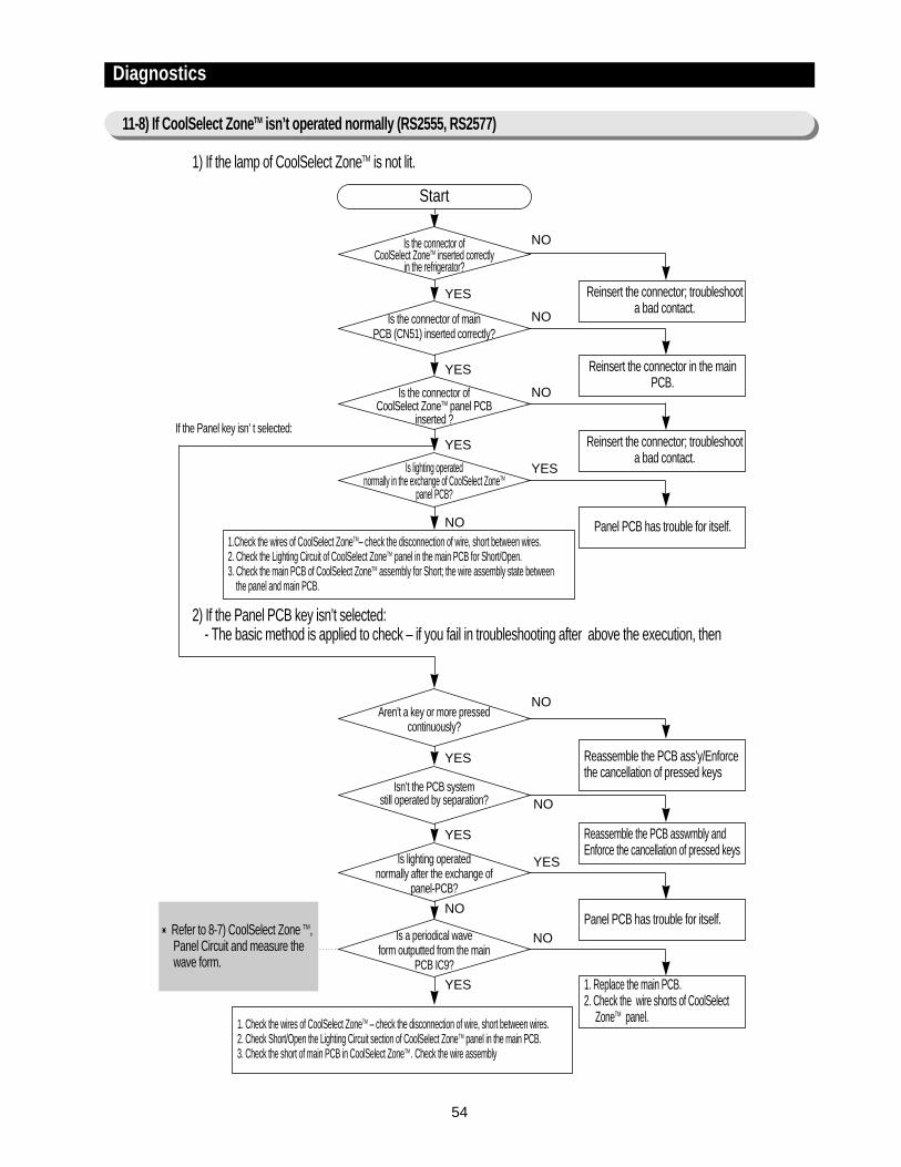
11-8) If CoolSelect ZoneTM isn’t operated normally (RS2555, RS2577)
1) If the lamp of CoolSelect ZoneTM is not lit.
2) If the Panel PCB key isn’t selected:- The basic method is applied to check – if you fail in troubleshooting after above the execution, then
Is the connector of CoolSelect ZoneTM inserted correctly
in the refrigerator?
Start
Reinsert the connector; troubleshoota bad contact.
Is the connector of main PCB (CN51) inserted correctly?
Reinsert the connector in the mainPCB.
Is the connector of CoolSelect ZoneTM panel PCB
inserted ?
Reinsert the connector; troubleshoota bad contact.
1.Check the wires of CoolSelect ZoneTM– check the disconnection of wire, short between wires.2. Check the Lighting Circuit of CoolSelect ZoneTM panel in the main PCB for Short/Open.3. Check the main PCB of CoolSelect ZoneTM assembly for Short; the wire assembly state between
the panel and main PCB.
1. Check the wires of CoolSelect ZoneTM – check the disconnection of wire, short between wires.2. Check Short/Open the Lighting Circuit section of CoolSelect ZoneTM panel in the main PCB.3. Check the short of main PCB in CoolSelect ZoneTM . Check the wire assembly
NO
NO
YES
YES
NO
Panel PCB has trouble for itself.
YES
YES
Is lighting operated normally in the exchange of CoolSelect ZoneTM
panel PCB?
If the Panel key isn’ t selected:
NO
YES Reassemble the PCB ass’y/Enforcethe cancellation of pressed keys
NOAren’t a key or more pressed
continuously?
YES Reassemble the PCB asswmbly andEnforce the cancellation of pressed keys
NOIsn’t the PCB system
still operated by separation?
NOPanel PCB has trouble for itself.
YESIs lighting operated normally after the exchange of
panel-PCB?
YES 1. Replace the main PCB.2. Check the wire shorts of CoolSelect
ZoneTM panel.
NOIs a periodical wave form outputted from the main
PCB IC9?
Refer to 8-7) CoolSelect Zone TM,Panel Circuit and measure thewave form.
55
Diagnostics
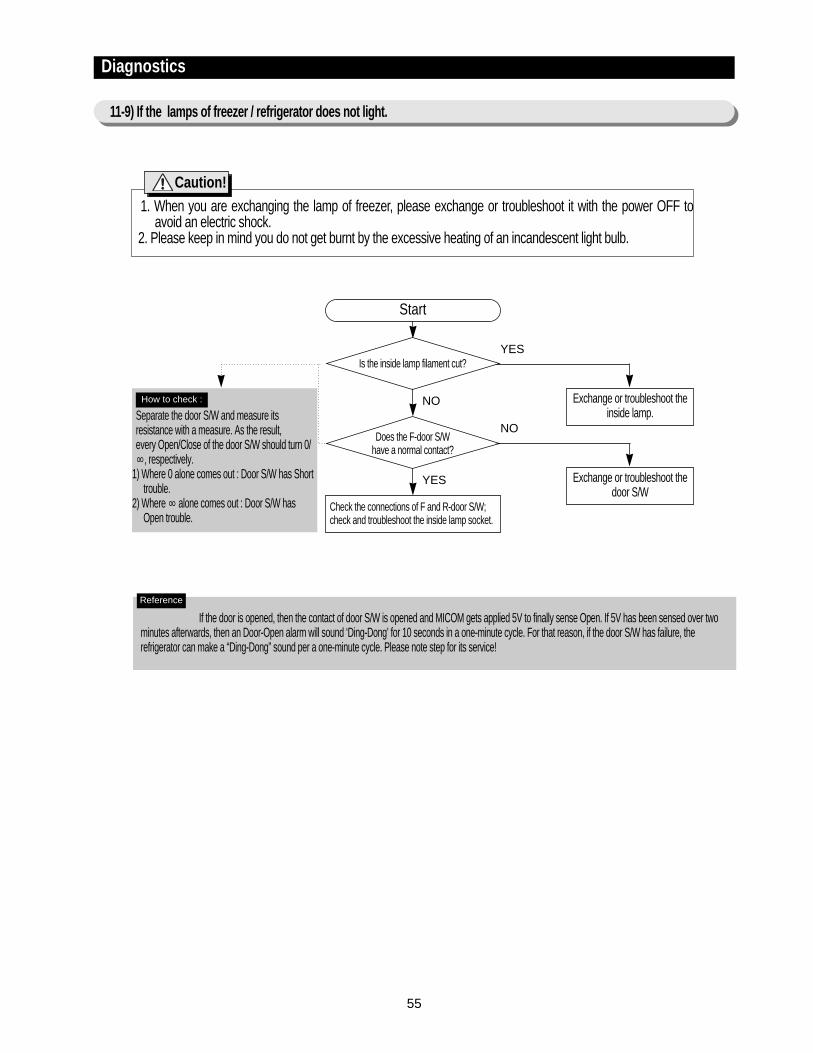
11-9) If the lamps of freezer / refrigerator does not light.
1. When you are exchanging the lamp of freezer, please exchange or troubleshoot it with the power OFF toavoid an electric shock.
2. Please keep in mind you do not get burnt by the excessive heating of an incandescent light bulb.
Is the inside lamp filament cut?
Start
Exchange or troubleshoot theinside lamp.
Does the F-door S/W have a normal contact?
Exchange or troubleshoot thedoor S/W
Check the connections of F and R-door S/W;check and troubleshoot the inside lamp socket.
YES
NO
NO
YES
Caution!
Separate the door S/W and measure itsresistance with a measure. As the result,every Open/Close of the door S/W should turn 0/∞, respectively.
1) Where 0 alone comes out : Door S/W has Shorttrouble.
2) Where ∞ alone comes out : Door S/W hasOpen trouble.
How to check :
If the door is opened, then the contact of door S/W is opened and MICOM gets applied 5V to finally sense Open. If 5V has been sensed over twominutes afterwards, then an Door-Open alarm will sound ‘Ding-Dong’ for 10 seconds in a one-minute cycle. For that reason, if the door S/W has failure, therefrigerator can make a “Ding-Dong” sound per a one-minute cycle. Please note step for its service!
Reference

56
Diagnostics
11-10) If the solenoid in the ice-chute cover doesn’t work :
Is the S/N(solenoid) for 0.3 sec operated after 5 seconds
from power ON?
Start
Is MICOM No. 27 on PCB maintaining High for 0.3 sec at the first
power ON?
Press Ice lever and keep it open.
Is the cover closed of S/N after about
7∼10 seconds?
With the ice S/W ON and ICE S/W on, ice-movement motor in F room?
Does C-E(between C and E) of TR Q701 turn ON for 0.3 sec?
MICOM control port is normal.
Exchange the main PCB assembly.
The S/N control PCB assembly andwire system have no trouble.
All the control system of cover ice-route has no trouble.
Check the ICE S/W, and troubleshootthe wire connection system.
- Main PCB and the sensing section ofice-S/W are normal.
- Check the operation of SSR71 andQ701.
Check the stop lever and supporttime-delay.
After replace TR Q701 and check SSR71 thenexchange the failed components or replace thePCB assembly. TR701 and SSR71 are normal
YES
YES
NO
YES
YES
YES
YES
YES
NO
NONO
NO
NO
1) Check if the solenoid is unconditionally operated for 0.3 sec, independent of the Open/Close condition of cover ice-route, aftera lapse of about 5 seconds from power ON. (Before installation, the cancellation of cover ice-route open is enabled.)
2) Check if the connector in upper hinge section is hook-up correctly.
Preliminary check
Subject to the ice S/W ON, do CN31 No. 2 and MICOM No. 45
get impressed 0V?
57
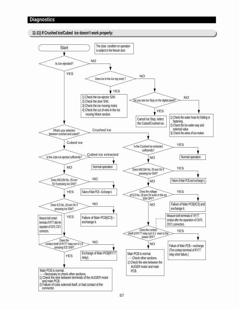
Is ice ejected?
What’s your selection between crushed and cubed?
Is the cube ice ejected sufficiently?
Does ice in the ice tray exist ?
Do you see Ice Stop on the digital panel?
Is the Crushed Ice extracted sufficiently?
Start The close condition on operationis subject to the freezer door.
1) Check the ice-ejector S/W.2) Check the door S/W.3) Check the ice moving motor.4) Check the cut of wire in the Ice
moving Motor section.Cancel Ice Stop, selectthe Cubed/Crushed ice.
Normal operation
1) Check the water hose for folding orfastening.
2) Check the ice-water-way andsolenoid value
3) Check the wires of ice-maker.
NO
Crushed ice
Cubed ice extractedNormal operation
YES
NO
Does MICOM No. 25 turn 5V if pressing Ice S/W?
Failure of Main PCB and exchange it.
YES
NO
Does the voltage of IC3 No. 18 turn 0V even in the ice
S/W OFF?
Failure of Main PCB(IC3) andexchange it.
YES
NO
Does the contact shelf of RY77 relay turn 0Ω even in the
power OFF?
Failure of Main PCB – exchange.(The contact terminal of RY77relay short failure.)
YES
NO
Failure of Main PCB. –Exchange it.
NO
Failure of Main PCB(IC3) –exchange it.
Main PCB is normal.- - - Necessary to check other sections.1) Check the wire between terminals of the AUGER motor
and main PCB.2) Failure of cube solenoid itself, or bad contact of the
connector.
Main PCB is normal.- - - Check other sections.1) Check the wire between the
AUGER motor and main PCB.
Measure both contactterminals of RY77 after theseparation of CN70, CN71connectors.
Measure both terminals of RY77contact after the separation of CN70,CN71 connectors.
NO
Exchange of Main PCB(RY77relay).
NO
Cubed ice
NO
Does MICOM No. 25 turn 5V if pressing Ice S/W?
Does IC3 No. 18 turn 0V if pressing Ice S/W?
Does the contact shelf of RY77 relay turn 0Ωif
pressing ICE S/W?
YES
YES
YES
NO
NO
YES
YES
YES
Diagnostics
11-11) If Crushed Ice/Cubed Ice doesn’t work properly:

58
12 . Illustrated Parts Catalog.
12-1) Freezer
269-1
9-2
59
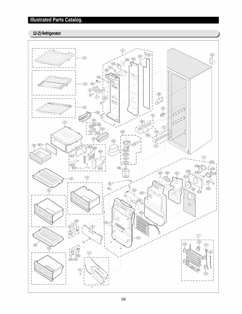
Illustrated Parts Catalog.
12-2) Refrigerator
28
32
31
30
29
29-2
29-1
60
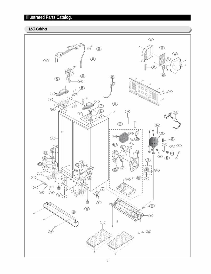
Illustrated Parts Catalog.
12-3) Cabinet
61
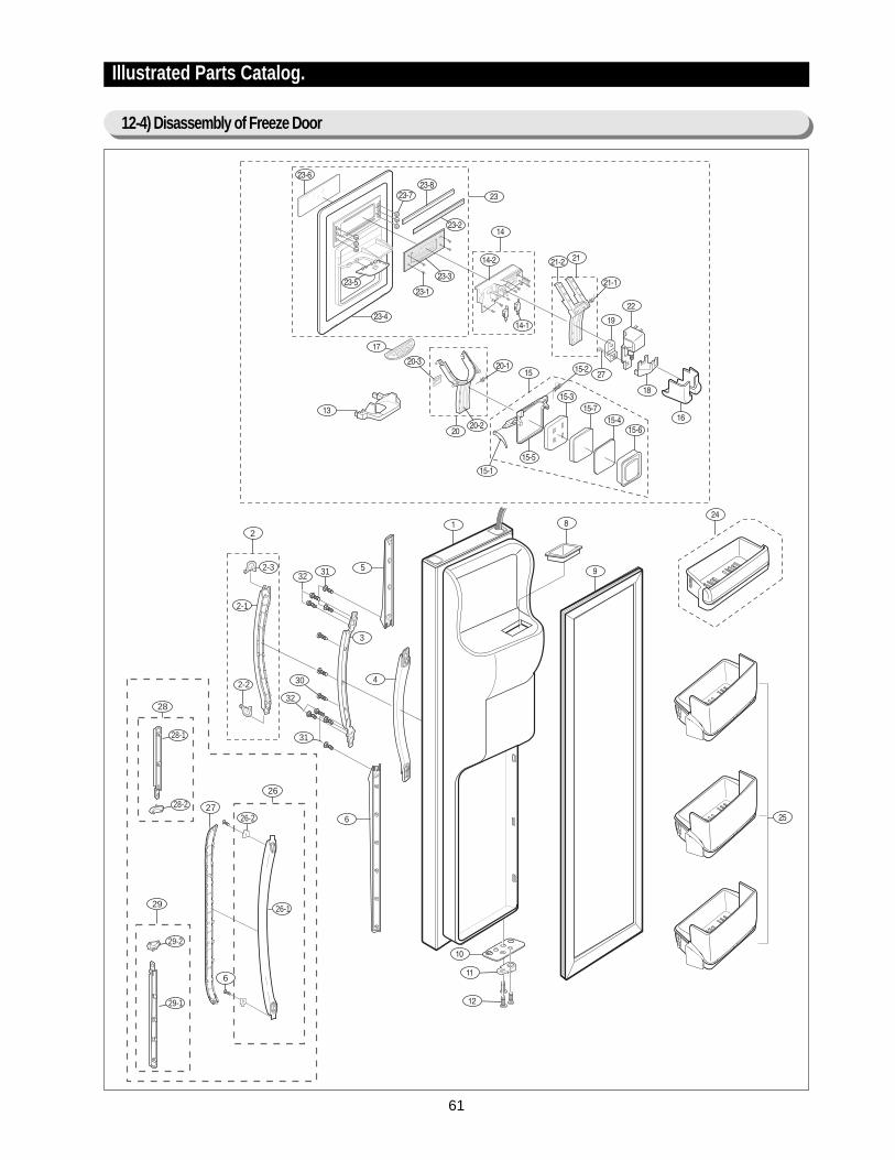
Illustrated Parts Catalog.
12-4) Disassembly of Freeze Door
26
26-2
6
29
27
29-2
29-1
26-1
28
28-1
28-2
2
2-3
3
32
32
31
31
30
5
4
6
2-1
2-2

62
Illustrated Parts Catalog.
12-5) Disassembly of Refrigerator Door
22
22-2
6
25
23
25-2
25-1
22-1
24
24-1
24-2
2728
2-3
2
2-1
2-2
28
27
264
6
3
5
63
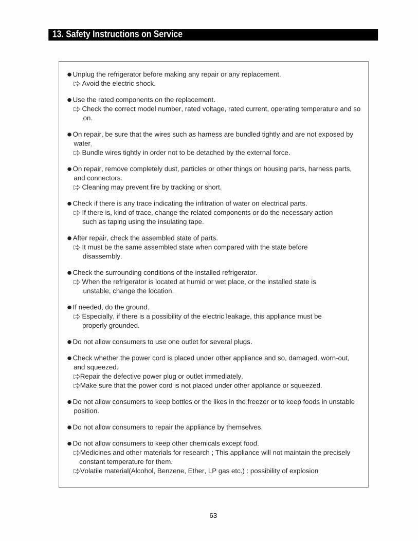
13. Safety Instructions on Service
Unplug the refrigerator before making any repair or any replacement.Avoid the electric shock.
Use the rated components on the replacement.Check the correct model number, rated voltage, rated current, operating temperature and so on.
On repair, be sure that the wires such as harness are bundled tightly and are not exposed bywater.
Bundle wires tightly in order not to be detached by the external force.
On repair, remove completely dust, particles or other things on housing parts, harness parts,and connectors.
Cleaning may prevent fire by tracking or short.
Check if there is any trace indicating the infitration of water on electrical parts.If there is, kind of trace, change the related components or do the necessary action such as taping using the insulating tape.
After repair, check the assembled state of parts.It must be the same assembled state when compared with the state before disassembly.
Check the surrounding conditions of the installed refrigerator.When the refrigerator is located at humid or wet place, or the installed state is unstable, change the location.
If needed, do the ground.Especially, if there is a possibility of the electric leakage, this appliance must be properly grounded.
Do not allow consumers to use one outlet for several plugs.
Check whether the power cord is placed under other appliance and so, damaged, worn-out, and squeezed.
Repair the defective power plug or outlet immediately.Make sure that the power cord is not placed under other appliance or squeezed.
Do not allow consumers to keep bottles or the likes in the freezer or to keep foods in unstableposition.
Do not allow consumers to repair the appliance by themselves.
Do not allow consumers to keep other chemicals except food.Medicines and other materials for research ; This appliance will not maintain the precisely constant temperature for them.Volatile material(Alcohol, Benzene, Ether, LP gas etc.) : possibility of explosion
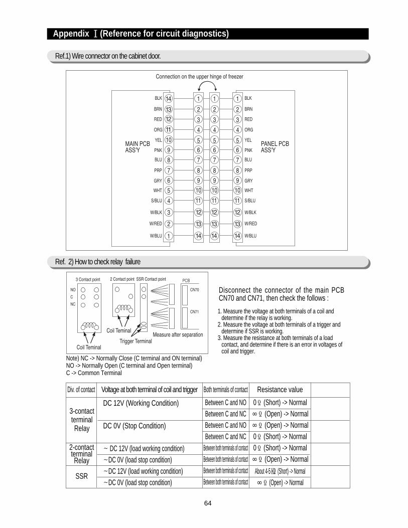
64
Appendix ⅠⅠ(Reference for circuit diagnostics)
Ref.1) Wire connector on the cabinet door.
Ref. 2) How to check relay failure
Div. of contact Voltage at both terminal of coil and trigger Both terminals of contact Resistance value
3-contactterminalRelay
0Ω (Short) -> Normal∞Ω (Open) -> Normal∞Ω (Open) -> Normal0Ω (Short) -> Normal0Ω (Short) -> Normal∞Ω (Open) -> Normal
About 4-5 (Short) -> Normal∞Ω (Open) -> Normal
Between C and NOBetween C and NCBetween C and NOBetween C and NC
Between both terminals of contactBetween both terminals of contactBetween both terminals of contactBetween both terminals of contact
DC 12V (Working Condition)
DC 0V (Stop Condition)
∼ DC 12V (load working condition)∼DC 0V (load stop condition)∼DC 12V (load working condition)∼DC 0V (load stop condition)
2-contactterminalRelay
SSR
Disconnect the connector of the main PCBCN70 and CN71, then check the follows :
1. Measure the voltage at both terminals of a coil anddetermine if the relay is working.
2. Measure the voltage at both terminals of a trigger anddetermine if SSR is working.
3. Measure the resistance at both terminals of a loadcontact, and determine if there is an error in voltages ofcoil and trigger.
Note) NC -> Normally Close (C terminal and ON terminal)NO -> Normally Open (C terminal and Open terminal)C -> Common Terminal
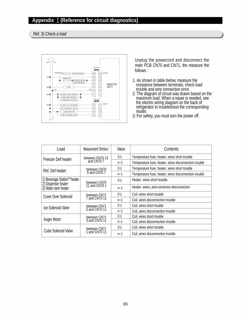
65
Appendix ⅠⅠ(Reference for circuit diagnostics)
Ref. 3) Check a load
Load Measurement Termina l Value Contents
Cover Over Solenoid
Ice Solenoid Valve
Auger Motor
Cube Solenoid Valve
1) Beverage StationTM heater2) Dispenser heater3) Water tank heater
Ref. Def heater
Freezer Def heater between CN70 13and CN70 7
between CN70 9 and CN70 7
between CN7011 and CN70 1
between CN71 7 and CN70 11
between CN71 5 and CN70 11
between CN71 3 and CN70 11
between CN71 1 and CN70 11
0Ω∞Ω0Ω∞Ω
0Ω∞Ω0Ω∞Ω0Ω∞Ω0Ω
∞Ω
0Ω
∞Ω
Temperature fuse, heater, wires short troubleTemperature fuse, heater, wires disconnection troubleTemperature fuse, heater, wires short troubleTemperature fuse, heater, wires disconnection troubleHeater, wires short trouble
Heater, wires, and connector disconnection
Coil, wires short troubleCoil, wires disconnection troubleCoil, wires short troubleCoil, wires disconnection troubleCoil, wires short troubleCoil, wires disconnection troubleCoil, wires short trouble
Coil, wires disconnection trouble
F-DEFROST HEATER
Unplug the powercord and disconnect themain PCB CN70 and CN71, the measure thefollows :
1. As shown in table below, measure theresistance between terminals, check loadtrouble and wire connection error.
2. The diagram of circuit was drawn based on themaximum load. When a repair is needed, seethe electric wiring diagram on the back ofrefrigerator to troubleshoot the correspondingmodel.
3. For safety, you must turn the power off.
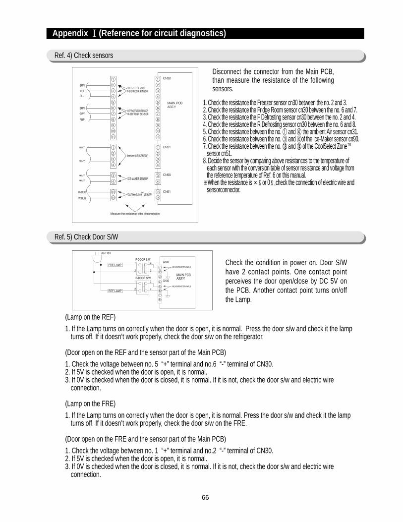
66
Check the condition in power on. Door S/Whave 2 contact points. One contact pointperceives the door open/close by DC 5V onthe PCB. Another contact point turns on/offthe Lamp.
(Lamp on the REF)
1. If the Lamp turns on correctly when the door is open, it is normal. Press the door s/w and check it the lampturns off. If it doesn’t work properly, check the door s/w on the refrigerator.
(Door open on the REF and the sensor part of the Main PCB)
1. Check the voltage between no. 5 “+” terminal and no.6 “-” terminal of CN30.2. If 5V is checked when the door is open, it is normal.3. If 0V is checked when the door is closed, it is normal. If it is not, check the door s/w and electric wire
connection.
(Lamp on the FRE)
1. If the Lamp turns on correctly when the door is open, it is normal. Press the door s/w and check it the lampturns off. If it doesn’t work properly, check the door s/w on the FRE.
(Door open on the FRE and the sensor part of the Main PCB)
1. Check the voltage between no. 1 “+” terminal and no.2 “-” terminal of CN30.2. If 5V is checked when the door is open, it is normal.3. If 0V is checked when the door is closed, it is normal. If it is not, check the door s/w and electric wire
connection.
Disconnect the connector from the Main PCB,than measure the resistance of the followingsensors.
1. Check the resistance the Freezer sensor cn30 between the no. 2 and 3.2. Check the resistance the Fridge Room sensor cn30 between the no. 6 and 7.3. Check the resistance the F Defrosting sensor cn30 between the no. 2 and 4.4. Check the resistance the R Defrosting sensor cn30 between the no. 6 and 8.5. Check the resistance between the no. ① and ④ the ambient Air sensor cn31.6. Check the resistance between the no. ③ and ④of the Ice-Maker sensor cn90.7. Check the resistance between the no. ⑬ and ⑭ of the CoolSelect Zone TM
sensor cn51.8. Decide the sensor by comparing above resistances to the temperature of
each sensor with the conversion table of sensor resistance and voltage fromthe reference temperature of Ref. 6 on this manual.
※When the resistance is ∞Ωor 0Ω,check the connection of electric wire andsensorconnector.
Appendix ⅠⅠ(Reference for circuit diagnostics)
Ref. 4) Check sensors
Ref. 5) Check Door S/W
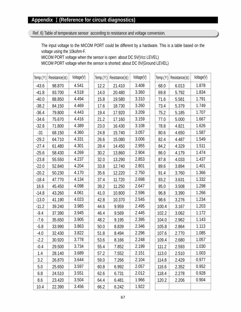
67
Appendix ⅠⅠ(Reference for circuit diagnostics)
Ref. 6) Table of temperature sensor according to resistance and voltage conversion.
Temp.()
-43.6-41.8-40.0-38.2-36.4-34.6-32.8-31
-29.2-27.4-25.6-23.8-22.0-20.2-18.416.6-14.8-13.0-11.2-9.4-7.6-5.8-4.0-2.2-0.41.43.25.06.88.610.4
Resistance()
98.87093.70088.85084.15079.80075.67071.80068.15064.71061.48058.43055.55052.84050.23047.77045.45043.26041.19039.24037.39035.65033.99032.43030.92029.50028.14026.87025.65024.51023.42022.390
Voltage(V)
4.5414.5184.4944.4694.4434.4164.3894.3604.3314.3014.2694.2374.2044.1704.1344.0984.0614.0233.9853.9453.9053.8633.8223.7783.7343.6893.6443.5973.5513.5043.456
The input voltage to the MICOM PORT could be different by a hardware. This is a table based on thevoltage using the 10kohm-F. MICOM PORT voltage when the sensor is open: about DC 5V(Vcc LEVEL)MICOM PORT voltage when the sensor is shorted: about DC 0V(Ground LEVEL)
Temp.()
12.214.015.817.619.421.223.024.826.628.430.232.033.835.637.439.241.042.844.646.448.250.051.853.655.457.259.060.862.664.466.2
Resistance()
21.41020.48019.58018.73017.92017.16016.43015.74015.08014.45013.86013.29012.74012.22011.72011.25010.80010.3709.9599.5699.1958.8398.4948.1667.8527.5527.2666.9926.7316.4816.242
Voltage(V)
3.4083.3603.3103.2603.2093.1593.1083.0573.0062.9552.9042.8532.8012.7502.6982.6472.5962.5452.4952.4452.3952.3462.2962.2482.1992.1512.1042.0572.0121.9661.922
Temp.()
68.069.871.673.475.277.078.880.682.484.286.087.889.691.493.295.096.898.6100.4102.2104.0105.8107.6109.4111.2113.0114.8116.6118.4120.2
Resistance()
6.0135.7925.5815.3795.1855.0004.8214.6504.4874.3294.1794.0333.8943.7603.6313.5083.3903.2763.1673.0622.9622.8642.7702.6802.5932.5102.4292.3522.2782.206
Voltage(V)
1.8781.8341.7911.7491.7071.6671.6261.5871.5491.5111.4741.4371.4011.3661.3321.2981.2661.2341.2031.1721.1431.1131.0851.0571.0301.0030.9770.9520.9280.904

68
1
2
3
4
5
6
7
8
9
10
11
12
13
DA41-00104E
DA41-00134A
DA41-00105C
DA41-00105D
DA32-00006B
DA32-10109V
DA32-10109W
DA32-00006A
DA32-10105U
DA32-10109X
DA41-00108A
3301-000016
DA27-00002A
Dispenser with CoolSelect ZoneTM
Dispenser
Dispenser with CoolSelect ZoneTM
Dispenser
502AT, PX-41C
502AT, PX-41C
502AT, PX-41C
502AT, PX-41C
502AT, PX-41C
502AT, PX-41C
CoolSelect ZoneTM MAIN+PANEL
-
Commonly used in ET-PJT
Main PCB ASS’Y
Main PCB ASS’Y
PANEL PCB ASS’Y
PANEL PCB ASS’Y
R-DEFROST Sensor
Ambient Temp. Sensor
F-Temp.Sensor
F-DEFROST Sensor
R-Temp.Sensor
CoolSelect ZoneTM Sensor
CoolSelect ZoneTM PCB ASS’Y
FERRITE CORE (LOCK TYPE)
NOISE FILTER
NO CODE-NO PART NAME SPECIFCATION Q’TY
※ The last no. of the code number such as DA41-xxxxx? for the Main PCB-ASS’Y could be changed byMICOM and option.
Appendix ⅠⅠ(Reference for circuit diagnostics)
Ref. 7) Service part lists of each circuit board.
1
1
1
1
1
1
1
1
1
1
1
1
1