samba electric shower - tlc electrical supplies · pdf filesamba 1 1 general 1.1 isolate the...
TRANSCRIPT
INSTALLERS PLEASE NOTE THESE INSTRUCTIONS ARE TO BE LEFT WITH THE USER
2180470A June 2005
Installation andoperating
instructions
Sambaelectricshower
Samba
ii
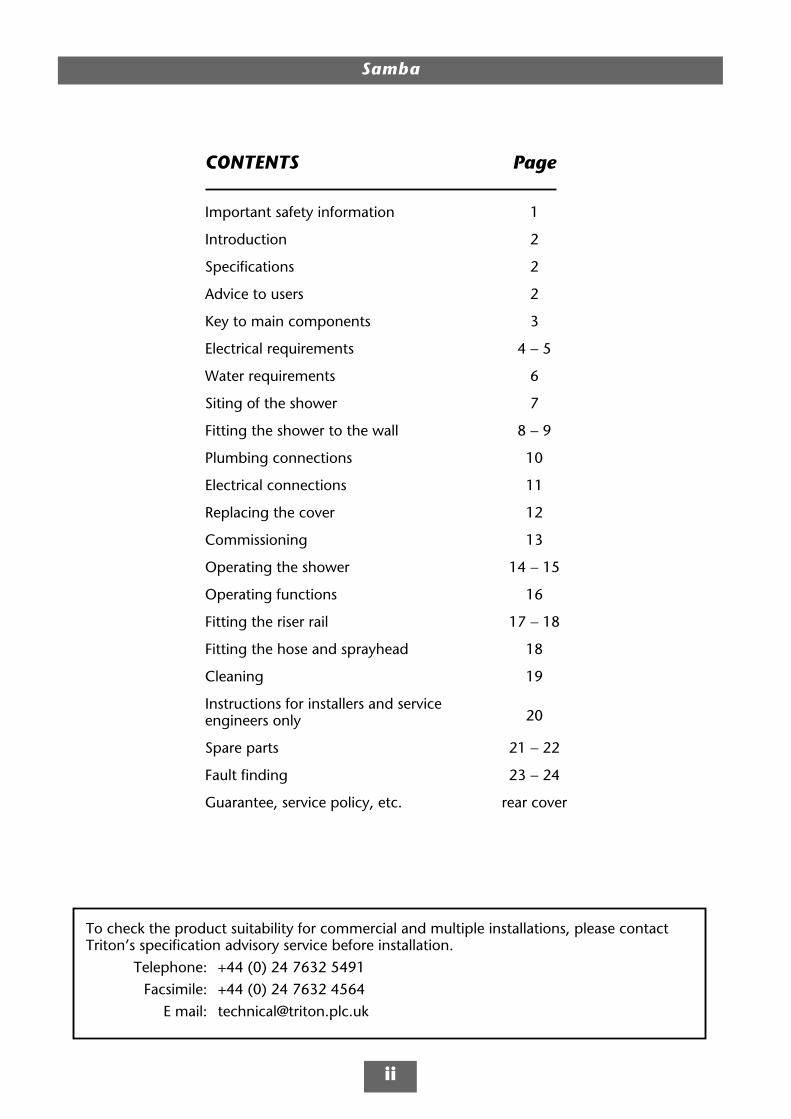
CONTENTS Page
Important safety information 1
Introduction 2
Specifications 2
Advice to users 2
Key to main components 3
Electrical requirements 4 − 5
Water requirements 6
Siting of the shower 7
Fitting the shower to the wall 8 − 9
Plumbing connections 10
Electrical connections 11
Replacing the cover 12
Commissioning 13
Operating the shower 14 − 15
Operating functions 16
Fitting the riser rail 17 − 18
Fitting the hose and sprayhead 18
Cleaning 19
Instructions for installers and serviceengineers only 20
Spare parts 21 − 22
Fault finding 23 − 24
Guarantee, service policy, etc. rear cover
To check the product suitability for commercial and multiple installations, please contactTriton’s specification advisory service before installation.
Telephone: +44 (0) 24 7632 5491Facsimile: +44 (0) 24 7632 4564
E mail: [email protected]
Samba
1
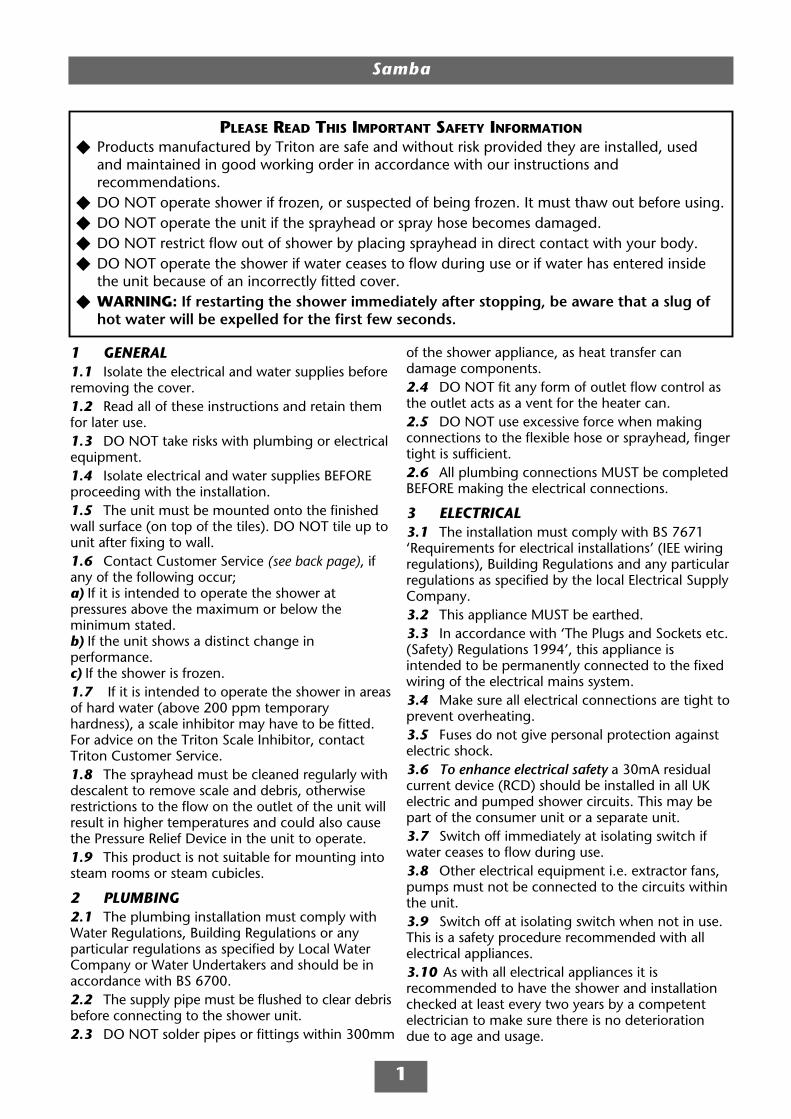
1 GENERAL1.1 Isolate the electrical and water supplies beforeremoving the cover.1.2 Read all of these instructions and retain themfor later use.1.3 DO NOT take risks with plumbing or electricalequipment.1.4 Isolate electrical and water supplies BEFOREproceeding with the installation.1.5 The unit must be mounted onto the finishedwall surface (on top of the tiles). DO NOT tile up tounit after fixing to wall.1.6 Contact Customer Service (see back page), ifany of the following occur;a) If it is intended to operate the shower atpressures above the maximum or below theminimum stated.b) If the unit shows a distinct change inperformance.c) If the shower is frozen.1.7 If it is intended to operate the shower in areasof hard water (above 200 ppm temporaryhardness), a scale inhibitor may have to be fitted.For advice on the Triton Scale Inhibitor, contactTriton Customer Service.1.8 The sprayhead must be cleaned regularly withdescalent to remove scale and debris, otherwiserestrictions to the flow on the outlet of the unit willresult in higher temperatures and could also causethe Pressure Relief Device in the unit to operate.1.9 This product is not suitable for mounting intosteam rooms or steam cubicles.
2 PLUMBING2.1 The plumbing installation must comply withWater Regulations, Building Regulations or anyparticular regulations as specified by Local WaterCompany or Water Undertakers and should be inaccordance with BS 6700.2.2 The supply pipe must be flushed to clear debrisbefore connecting to the shower unit.2.3 DO NOT solder pipes or fittings within 300mm
of the shower appliance, as heat transfer candamage components.2.4 DO NOT fit any form of outlet flow control asthe outlet acts as a vent for the heater can.2.5 DO NOT use excessive force when makingconnections to the flexible hose or sprayhead, fingertight is sufficient.2.6 All plumbing connections MUST be completedBEFORE making the electrical connections.
3 ELECTRICAL3.1 The installation must comply with BS 7671‘Requirements for electrical installations’ (IEE wiringregulations), Building Regulations and any particularregulations as specified by the local Electrical SupplyCompany.3.2 This appliance MUST be earthed.3.3 In accordance with ‘The Plugs and Sockets etc.(Safety) Regulations 1994’, this appliance isintended to be permanently connected to the fixedwiring of the electrical mains system.3.4 Make sure all electrical connections are tight toprevent overheating.3.5 Fuses do not give personal protection againstelectric shock.3.6 To enhance electrical safety a 30mA residualcurrent device (RCD) should be installed in all UKelectric and pumped shower circuits. This may bepart of the consumer unit or a separate unit.3.7 Switch off immediately at isolating switch ifwater ceases to flow during use.3.8 Other electrical equipment i.e. extractor fans,pumps must not be connected to the circuits withinthe unit.3.9 Switch off at isolating switch when not in use.This is a safety procedure recommended with allelectrical appliances.3.10 As with all electrical appliances it isrecommended to have the shower and installationchecked at least every two years by a competentelectrician to make sure there is no deteriorationdue to age and usage.
PLEASE READ THIS IMPORTANT SAFETY INFORMATION
Products manufactured by Triton are safe and without risk provided they are installed, usedand maintained in good working order in accordance with our instructions andrecommendations.DO NOT operate shower if frozen, or suspected of being frozen. It must thaw out before using.DO NOT operate the unit if the sprayhead or spray hose becomes damaged.DO NOT restrict flow out of shower by placing sprayhead in direct contact with your body.DO NOT operate the shower if water ceases to flow during use or if water has entered insidethe unit because of an incorrectly fitted cover.WARNING: If restarting the shower immediately after stopping, be aware that a slug ofhot water will be expelled for the first few seconds.

Samba
2
ADVICE TO USERSThe following points will help you understandhow the shower operates:
a The electric heating elements operate at aconstant rate at your chosen power setting. It isthe rate of the water passing through the heaterunit which determines the shower temperatureat any given setting (the slower the flow thehotter the water becomes, and the faster theflow the cooler the water).
b During winter, mains water supply will becooler than in summer. Therefore thetemperature of the shower will vary betweenseasons on any one setting of the temperaturecontrol, e.g. if you have chosen setting number6 as your preferred shower temperature in thesummer, you will have to increase that numberduring winter by adjusting the temperaturecontrol clockwise (which in effect slows thewater flow).
c The stabiliser valve minimises variations inshower temperature during mains waterpressure changes. If changes in showertemperature are experienced during normal use,it will most likely be caused by the waterpressure falling near to or below the minimumlevel. The drop in pressure may be due to waterbeing drawn off at other points in the housewhilst the shower is in use. If pressure dropsappreciably below the minimum, the heatingelements will automatically cut out.
If ever the water becomes too hot and youcannot obtain cooler water, first check that thesprayplate in the sprayhead has not becomeblocked.
DO NOT place items such as soap or shampoobottles on top of the unit. Liquid could seepthrough the joint between the cover andbackplate, and possibly damage the sealingrubber.
Replacement parts can be ordered from CustomerService. See ‘spare parts’ for details and part numbers.
Due to continuous improvement and updating,specification may be altered without prior notice.
INTRODUCTION
This book contains all the necessary fitting andoperating instructions for your Triton electricshower. Please read them carefully.
The shower installation must be carried out by asuitably qualified person and in the sequence ofthis instruction book.
Care taken during the installation will provide along, trouble-free life from your shower.
SPECIFICATIONSElectricalNominal power Nominal powerrating at 240V rating at 230V8.5kW – (40A MCB rating) 7.8kW – (40A MCB rating)
WaterInlet connection – 15mm diameter.Outlet connection – ½” BSP male thread.
Entry PointsWater – top, bottom, back, left or right.Cable – top, bottom, back, left or right.
MaterialsBackplate, cover, controls, sprayhead – ABS.Sprayplate – Acetal.Elements – Minerally insulated corrosionresistant metal sheathing.
DimensionsHeight − 305mmWidth − 210mmDepth − 110mm
Standards and ApprovalsWaterproof rating IPX4.
Complies with the requirements of currentBritish and European safety standards forhousehold and similar electrical appliances.
Complies with requirements of the BritishElectrotechnical Approvals Board (BEAB).
Meets with Compliance with EuropeanCommunity Directives (CE).

Samba
3
255mm
210mm
305mm
59mm
1
2
2
3
3
3
3
45
6
8
7
910
11
12
13
16
14
17
15
Fig.1KEY TO MAIN COMPONENTS
Inside unit (fig.1)
1 Top cable/pipe entry
2 Wall screw fixings
3 Cover screw fixings
4 Thermal safety cut-out (main)
5 Power selector assembly
6 Power neon
7 Can and element assembly
8 Pressure switch assembly
9 Stabilising valve
10 Terminal block
11 Earth connection
12 Solenoid valve
13 Water inlet
14 Outlet temperature limiter
15 Pressure relief device (PRD)
16 Trimplate
17 Shower outlet
Pack contents
Shower unit
Sprayhead
Riser rail kit and fittings
Flexible hose
Screw fixing kit
Instructions, guarantee, etc.
NOTE: Wiring has not been depicted for reason of clarity.
Samba
4
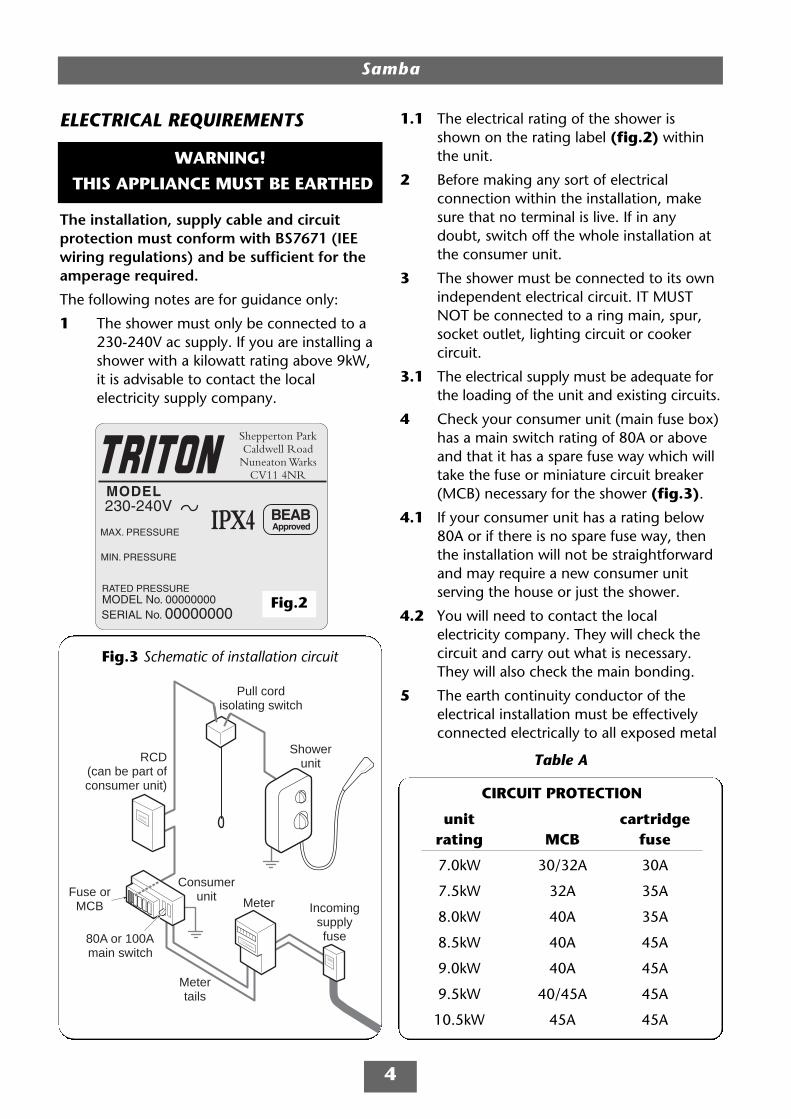
ELECTRICAL REQUIREMENTS
The installation, supply cable and circuitprotection must conform with BS7671 (IEEwiring regulations) and be sufficient for theamperage required.
The following notes are for guidance only:
1 The shower must only be connected to a230-240V ac supply. If you are installing ashower with a kilowatt rating above 9kW,it is advisable to contact the localelectricity supply company.
Fig.2
WARNING!
THIS APPLIANCE MUST BE EARTHED
Meter Incomingsupplyfuse
Metertails
Consumerunit
Pull cordisolating switch
Showerunit
Fuse orMCB
RCD(can be part ofconsumer unit)
80A or 100Amain switch
Fig.3 Schematic of installation circuit
1.1 The electrical rating of the shower isshown on the rating label (fig.2) withinthe unit.
2 Before making any sort of electricalconnection within the installation, makesure that no terminal is live. If in anydoubt, switch off the whole installation atthe consumer unit.
3 The shower must be connected to its ownindependent electrical circuit. IT MUSTNOT be connected to a ring main, spur,socket outlet, lighting circuit or cookercircuit.
3.1 The electrical supply must be adequate forthe loading of the unit and existing circuits.
4 Check your consumer unit (main fuse box)has a main switch rating of 80A or aboveand that it has a spare fuse way which willtake the fuse or miniature circuit breaker(MCB) necessary for the shower (fig.3).
4.1 If your consumer unit has a rating below80A or if there is no spare fuse way, thenthe installation will not be straightforwardand may require a new consumer unitserving the house or just the shower.
4.2 You will need to contact the localelectricity company. They will check thecircuit and carry out what is necessary.They will also check the main bonding.
5 The earth continuity conductor of theelectrical installation must be effectivelyconnected electrically to all exposed metal
CIRCUIT PROTECTION
unit cartridgerating MCB fuse
7.0kW 30/32A 30A
7.5kW 32A 35A
8.0kW 40A 35A
8.5kW 40A 45A
9.0kW 40A 45A
9.5kW 40/45A 45A
10.5kW 45A 45A
Table A

Samba
5
parts of other appliances and services inthe room in which the shower is to beinstalled, to conform to current IEEregulations.
5.1 All exposed metallic parts in the bathroommust be bonded together using a cable ofat least 4mm2 cross sectional area. Theseparts include metal baths, radiators, waterpipes, taps and waste fittings.
6 For close circuit protection DO NOT use arewireable fuse. Instead use a suitablyrated miniature circuit breaker or cartridgefuse (see table A).
6.1 In the interest of electrical safety a 30mAresidual current device (RCD) should beinstalled in all UK electric and pumpedshower circuits. This may be part of theconsumer unit or a separate unit.
7 A 45 amp double pole isolating switchwith a minimum contact gap of 3mm inboth poles must be incorporated in thecircuit.
7.1 It must have a mechanical indicatorshowing when the switch is in the OFFposition, and the wiring must beconnected to the switch without the use ofa plug or socket outlet.
7.2 The switch must be accessible and clearlyidentifiable, but out of reach of a person
using a fixed bath or shower, except forthe cord of a cord operated switch, andshould be placed so that it is not possibleto touch the switch body while standing ina bath or shower cubicle. It should bereadily accessible to switch off after usingthe shower.
8 Where shower cubicles are located in anyrooms other than bathrooms, all socketoutlets in those rooms must be protectedby a 30mA RCD.
9 To obtain full advantage of the powerprovided by the shower, use the shortestcable route possible from the consumerunit to the shower.
9.1 The current carrying capacity of the cablemust be at least that of the shower circuitprotection (see table B).
9.2 It is also necessary to satisfy thedisconnection time and thermalconstraints which means that for any givencombination of current demand, voltagedrop and cable size, there is a maximumpermissible circuit length.
10 The shower circuit should be separatedfrom other circuits by at least twice thediameter of the cable or conduit.
10.1 The current rating will be reduced if thecabling is bunched with others,surrounded by thermal loft or wallinsulation or placed in areas where theambient temperature is above 30°C.Under these conditions, derating factorsapply and it is necessary to select a largercable size.
10.2 In the majority of installations, the cablewill unavoidably be placed in one or moreof the above conditions. This being so, it isstrongly recommended to use a minimumof 10mm cabling throughout the showerinstallation.
10.3 It is essential that individual site conditionsare assessed by a competent electrician todetermine correct cable size andpermissible circuit length.
Twin and earth PVC insulated cable
CURRENT CARRYING CAPACITYclipped direct or
installed in an in conduit buried in a noninsulated wall or trunking insulated wall
6mm2 6mm2 6mm2
32A 38A 46A
10mm2 10mm2 10mm2
43A 52A 63A
16mm2 16mm2 16mm2
57A 69A 85A
Note: Cable selection is dependenton derating factors
Table B

Samba
6
WATER REQUIREMENTS
The installation must be in accordance withWater Regulations and Byelaws.
To ensure activation of the heating elements,the shower must be connected to a mainswater supply with a minimum running pressureof 100kPa (1.0 bar) at a minimum flow rate ofeight litres per minute for the 8.5kW ratedmodel.
For all models the maximum static pressuremust not exceed 1000kPa (10 bar).
Note: If the stated flow rates are not available,it may not be possible to achieve the bestperformance from the unit throughout theyear.
During periods of high ambient temperatures itmay be necessary to select a low power settingto achieve your preferred shower temperature.
The water supply can be taken from a coldwater storage cistern provided there is aminimum head of ten metres above thesprayhead. It must be an independent supply tothe shower only.
If it is intended to operate the shower atpressures above the maximum or below theminimum stated, contact Customer Service foradvice.
Fig.4 shows a typical system layout.
DO NOT use jointing compounds on anypipe fittings for the installation.
Isolatingstopvalve
Mainswatersupply
Showerunit
Mains electric supply (via double pole switch)
Doublepole
isolatingswitch
Separate permanentlyconnected supply
from consumer unit
Fig.4 Diagrammatic view (not to scale)
WARNING!
The shower must not be positionedwhere it will be subjected to
freezing conditions.
Samba
7
Outline of bath,shower trayor cubicle
Mains coldwater supply (either top,
side, bottom or rear entry)
Shower unit canbe mountedeither sideof riser rail
25mm minimumShower unit
must notbe withinan area1 metre
from base
Height of sprayhead
and shower to suit user'srequirement
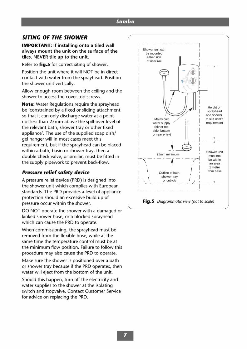
Fig.5 Diagrammatic view (not to scale)
SITING OF THE SHOWERIMPORTANT: If installing onto a tiled wallalways mount the unit on the surface of thetiles. NEVER tile up to the unit.
Refer to fig.5 for correct siting of shower.
Position the unit where it will NOT be in directcontact with water from the sprayhead. Positionthe shower unit vertically.
Allow enough room between the ceiling and theshower to access the cover top screws.
Note: Water Regulations require the sprayheadbe ‘constrained by a fixed or sliding attachmentso that it can only discharge water at a pointnot less than 25mm above the spill-over level ofthe relevant bath, shower tray or other fixedappliance’. The use of the supplied soap dish/gel hanger will in most cases meet thisrequirement, but if the sprayhead can be placedwithin a bath, basin or shower tray, then adouble check valve, or similar, must be fitted inthe supply pipework to prevent back-flow.
Pressure relief safety deviceA pressure relief device (PRD) is designed intothe shower unit which complies with Europeanstandards. The PRD provides a level of applianceprotection should an excessive build up ofpressure occur within the shower.
DO NOT operate the shower with a damaged orkinked shower hose, or a blocked sprayheadwhich can cause the PRD to operate.
When commissioning, the sprayhead must beremoved from the flexible hose, while at thesame time the temperature control must be atthe minimum flow position. Failure to follow thisprocedure may also cause the PRD to operate.
Make sure the shower is positioned over a bathor shower tray because if the PRD operates, thenwater will eject from the bottom of the unit.
Should this happen, turn off the electricity andwater supplies to the shower at the isolatingswitch and stopvalve. Contact Customer Servicefor advice on replacing the PRD.

Samba
8
FITTING THE SHOWER TO THE WALL
Note: The control knobs are an integral part ofthe cover – DO NOT attempt to remove them.
Lift the cover from the backplate. To access thepipe and cable connections, remove thetrimplate by removing the two fixings screws(fig.6).
Entry positions for the mains water and electriccable are from the top, bottom, either side orfrom the back.
Note: Deviations from the designated entrypoints will invalidate product approvals.
If a bottom entry has been chosen, fit thesupplied pipe trim in the top of the backplate(fig.7).
If a top entry has been chosen, fit the suppliedpipe trim in the bottom of the trimplate (fig.8).
If a side entry is required, the trimplate side willhave to be cut. With the elbow compressionfitted on the outlet, temporarily place thetrimplate into position, then mark the pipe entryon the side of the trimplate. Using a juniorhacksaw, carefully remove the appropriate area.
If installing a feed pipe from the back orbottom, the centre of the inlet valve to the wallsurface is 20mm (fig.9).
Note: If entry is from the back, the nut of thecompression fitting will be partially behind thesurface of the wall. This area MUST be left clearwhen plastering over the pipework in order tomake the nut accessible for future adjustments.
After choosing the site for the shower, use thebackplate as a template and mark the two fixingholes (fig.10). Drill and plug the wall. (Thewallplugs provided are suitable for most brick walls– use an appropriate masonry drill, but if the wallis plasterboard or a soft building block, you mustuse suitable wallplugs and a suitable drill bit).
Fig.8
Fig.7
Fig.6
IMPORTANT: The unit must be mountedon a flat surface which covers the fullwidth and length of the backplate. It isimportant that the wall surface is flatotherwise difficulty may be encounteredwhen fitting the cover and subsequentoperation of the unit may be impaired.

Samba
Screw the top fixing screw into position leavingthe base of the screw head protruding 6mm outfrom the wall.
Hook the backplate over the top screw and fitthe bottom fixing screw into position.
DO NOT fully tighten the screws at this stage, asthe fixing holes are elongated to allow for out ofsquare adjustment after the plumbingconnections have been completed.
20 mm
Fig.10
Fig.9
9
Samba
10
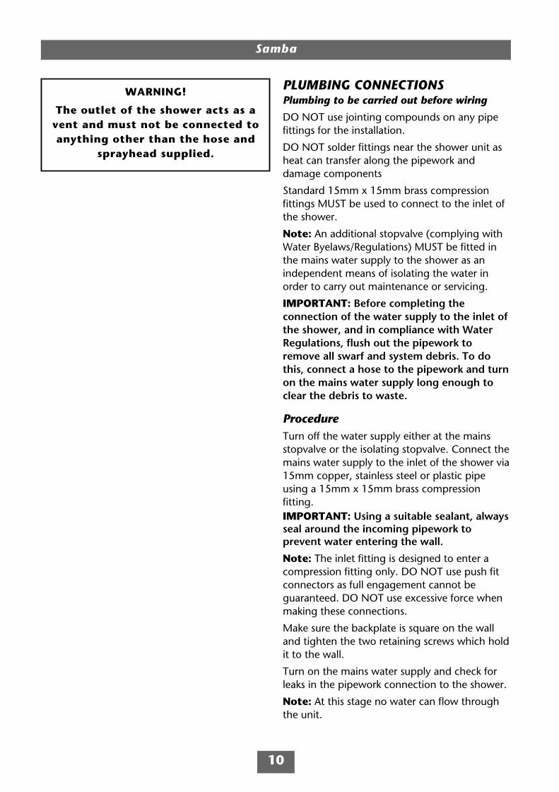
PLUMBING CONNECTIONSPlumbing to be carried out before wiring
DO NOT use jointing compounds on any pipefittings for the installation.
DO NOT solder fittings near the shower unit asheat can transfer along the pipework anddamage components
Standard 15mm x 15mm brass compressionfittings MUST be used to connect to the inlet ofthe shower.
Note: An additional stopvalve (complying withWater Byelaws/Regulations) MUST be fitted inthe mains water supply to the shower as anindependent means of isolating the water inorder to carry out maintenance or servicing.
IMPORTANT: Before completing theconnection of the water supply to the inlet ofthe shower, and in compliance with WaterRegulations, flush out the pipework toremove all swarf and system debris. To dothis, connect a hose to the pipework and turnon the mains water supply long enough toclear the debris to waste.
ProcedureTurn off the water supply either at the mainsstopvalve or the isolating stopvalve. Connect themains water supply to the inlet of the shower via15mm copper, stainless steel or plastic pipeusing a 15mm x 15mm brass compressionfitting.IMPORTANT: Using a suitable sealant, alwaysseal around the incoming pipework toprevent water entering the wall.
Note: The inlet fitting is designed to enter acompression fitting only. DO NOT use push fitconnectors as full engagement cannot beguaranteed. DO NOT use excessive force whenmaking these connections.
Make sure the backplate is square on the walland tighten the two retaining screws which holdit to the wall.
Turn on the mains water supply and check forleaks in the pipework connection to the shower.
Note: At this stage no water can flow throughthe unit.
WARNING!
The outlet of the shower acts as avent and must not be connected toanything other than the hose and
sprayhead supplied.
Samba
11
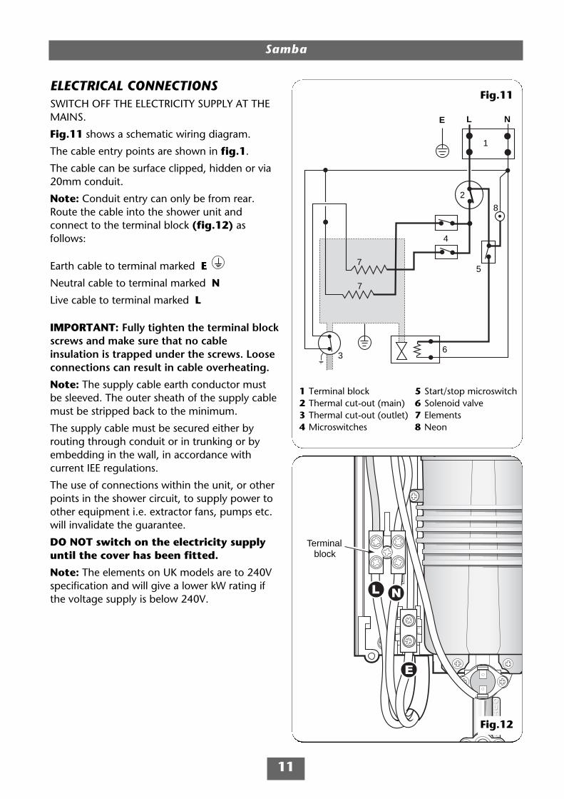
ELECTRICAL CONNECTIONSSWITCH OFF THE ELECTRICITY SUPPLY AT THEMAINS.
Fig.11 shows a schematic wiring diagram.
The cable entry points are shown in fig.1.
The cable can be surface clipped, hidden or via20mm conduit.
Note: Conduit entry can only be from rear.Route the cable into the shower unit andconnect to the terminal block (fig.12) asfollows:
Earth cable to terminal marked E
Neutral cable to terminal marked N
Live cable to terminal marked L
IMPORTANT: Fully tighten the terminal blockscrews and make sure that no cableinsulation is trapped under the screws. Looseconnections can result in cable overheating.
Note: The supply cable earth conductor mustbe sleeved. The outer sheath of the supply cablemust be stripped back to the minimum.
The supply cable must be secured either byrouting through conduit or in trunking or byembedding in the wall, in accordance withcurrent IEE regulations.
The use of connections within the unit, or otherpoints in the shower circuit, to supply power toother equipment i.e. extractor fans, pumps etc.will invalidate the guarantee.
DO NOT switch on the electricity supplyuntil the cover has been fitted.
Note: The elements on UK models are to 240Vspecification and will give a lower kW rating ifthe voltage supply is below 240V.
2
3
4
57
7
L N
6
E
8
1
Terminalblock
Fig.12
Fig.11
1 Terminal block2 Thermal cut-out (main)3 Thermal cut-out (outlet)4 Microswitches
5 Start/stop microswitch6 Solenoid valve7 Elements8 Neon

Samba
12
REPLACING THE COVERLocate the trimplate into the backplate andsecure with the two fixing screws.
The power selector spindle must be aligned asshown (fig.13).
To ensure that the temperature control iscorrectly positioned on the stabilising valve,temporarily place the cover in position so thatthe splines engage and rotate the temperaturecontrol fully anti-clockwise.
Remove the cover and position the temperaturecontrol knob so that it points to the ‘1’ position(fig.14). Position the power selector to the‘STOP’ position (fig.15).
Replace the cover squarely to the backplate andguide into position so that the knobs locatecorrectly into the splined spindles. Should anydifficulty arise, recheck the points above.
Secure the cover in position with the fourretaining screws.
Fig.13
Fig.14
Fig.15
Samba
13
Fig.16
Fig.17
Fig.19
Fig.18
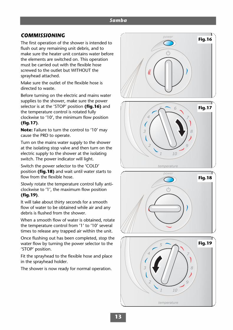
COMMISSIONINGThe first operation of the shower is intended toflush out any remaining unit debris, and tomake sure the heater unit contains water beforethe elements are switched on. This operationmust be carried out with the flexible hosescrewed to the outlet but WITHOUT thesprayhead attached.
Make sure the outlet of the flexible hose isdirected to waste.
Before turning on the electric and mains watersupplies to the shower, make sure the powerselector is at the ‘STOP’ position (fig.16) andthe temperature control is rotated fullyclockwise to ‘10’, the minimum flow position(fig.17).
Note: Failure to turn the control to ‘10’ maycause the PRD to operate.
Turn on the mains water supply to the showerat the isolating stop valve and then turn on theelectric supply to the shower at the isolatingswitch. The power indicator will light.
Switch the power selector to the ‘COLD’position (fig.18) and wait until water starts toflow from the flexible hose.
Slowly rotate the temperature control fully anti-clockwise to ‘1’, the maximum flow position(fig.19).
It will take about thirty seconds for a smoothflow of water to be obtained while air and anydebris is flushed from the shower.
When a smooth flow of water is obtained, rotatethe temperature control from ‘1’ to ‘10’ severaltimes to release any trapped air within the unit.
Once flushing out has been completed, stop thewater flow by turning the power selector to the‘STOP’ position.
Fit the sprayhead to the flexible hose and placein the sprayhead holder.
The shower is now ready for normal operation.

OPERATING THE SHOWERIMPORTANT: Make sure the commissioningprocedure has been carried out.
To start the showerTurning the power selector to the red or bluesymbol positions will start water to flow.
To stop the showerSwitch the power selector to the ‘STOP’position and water will cease to flow.
To use the power selectorThe power selector has four positions − stop,cold, economy and high − as shown (fig.20).
STOP is to switch off the electric and watersupply at the shower – no flow or power isused.
Blue symbol is cold water only. Adjusting thetemperature control at this setting will onlyalter the force of the water from the sprayhead.IT WILL NOT ALTER THE WATER TEMPERATURE.
Single red symbol is an economy settingfor using less power during warmer months.Temperature adjustment at this setting is viathe temperature control.
Note: If the stated flow rate required for theunit cannot be met due to low water pressure,it will be necessary to operate the unit on thissetting during the warmer months because offlow rate limitations entering the unit.
Double red symbol is a high setting whichallows the highest flow achievable for yourpreferred temperature. This setting shouldnormally be regarded as optimum showerperformance throughout the year. Temperatureadjustment at this setting is via the temperaturecontrol.
Samba
14
Power selector
Stop
Economy
High
Temperaturecontrol
Cold
Fig.20
WARNING!
If restarting immediately afterstopping, be aware that a slug ofhot water will be expelled for the
first few seconds.

Samba
15
To adjust the shower temperatureAlter the water temperature by increasing ordecreasing the flow rate of the water through theshower via the temperature control (fig.20).
After obtaining your preferred showertemperature, the number can be rememberedand left as the normal setting and should onlyneed to be altered to compensate for seasonalchanges in ambient water temperature.
Note: The preferred number on ‘economy’ willgive a different temperature to the samenumber position on ‘high’.
To decrease the shower temperatureTurn the temperature control anti-clockwise(fig.21); this will increase the flow of waterthrough the shower and be indicated by thelower numbers.
To increase the shower temperatureTurn the temperature control clockwise(fig.22); this will decrease the flow of waterthrough the shower and be indicated by thehigher numbers.
Note: It is advisable to be certain that theshowering temperature is satisfactory by testingwith your hand before stepping under thesprayhead. There will always be a time delay ofa few seconds between selecting a flow rate andthe water reaching the stable temperature forthat flow rate.
CAUTION: It is recommended that personswho may have difficulty understanding oroperating the shower controls should not beleft unattended while showering. Specialconsideration should be given to youngchildren and the less able bodied.
Fig.21
Fig.22
Samba
16
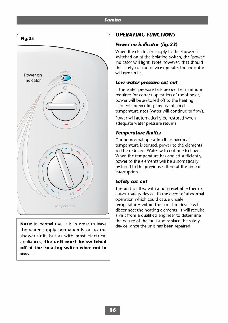
OPERATING FUNCTIONS
Power on indicator (fig.23)When the electricity supply to the shower isswitched on at the isolating switch, the ‘power’indicator will light. Note however, that shouldthe safety cut-out device operate, the indicatorwill remain lit.
Low water pressure cut-outIf the water pressure falls below the minimumrequired for correct operation of the shower,power will be switched off to the heatingelements preventing any maintainedtemperature rises (water will continue to flow).
Power will automatically be restored whenadequate water pressure returns.
Temperature limiterDuring normal operation if an overheattemperature is sensed, power to the elementswill be reduced. Water will continue to flow.When the temperature has cooled sufficiently,power to the elements will be automaticallyrestored to the previous setting at the time ofinterruption.
Safety cut-outThe unit is fitted with a non-resettable thermalcut-out safety device. In the event of abnormaloperation which could cause unsafetemperatures within the unit, the device willdisconnect the heating elements. It will requirea visit from a qualified engineer to determinethe nature of the fault and replace the safetydevice, once the unit has been repaired.
Power onindicator
Fig.23
Note: In normal use, it is in order to leavethe water supply permanently on to theshower unit, but as with most electricalappliances, the unit must be switchedoff at the isolating switch when not inuse.
Samba
17
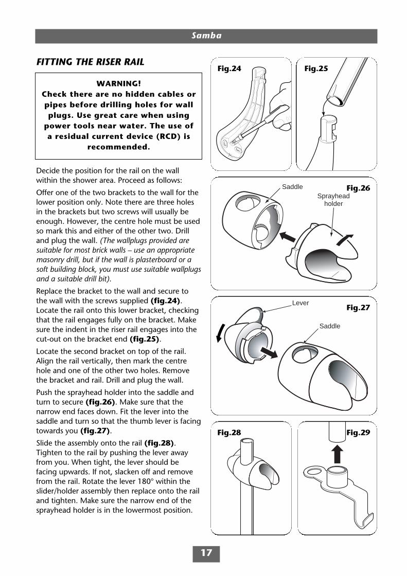
FITTING THE RISER RAIL
Decide the position for the rail on the wallwithin the shower area. Proceed as follows:
Offer one of the two brackets to the wall for thelower position only. Note there are three holesin the brackets but two screws will usually beenough. However, the centre hole must be usedso mark this and either of the other two. Drilland plug the wall. (The wallplugs provided aresuitable for most brick walls – use an appropriatemasonry drill, but if the wall is plasterboard or asoft building block, you must use suitable wallplugsand a suitable drill bit).
Replace the bracket to the wall and secure tothe wall with the screws supplied (fig.24).Locate the rail onto this lower bracket, checkingthat the rail engages fully on the bracket. Makesure the indent in the riser rail engages into thecut-out on the bracket end (fig.25).
Locate the second bracket on top of the rail.Align the rail vertically, then mark the centrehole and one of the other two holes. Removethe bracket and rail. Drill and plug the wall.
Push the sprayhead holder into the saddle andturn to secure (fig.26). Make sure that thenarrow end faces down. Fit the lever into thesaddle and turn so that the thumb lever is facingtowards you (fig.27).
Slide the assembly onto the rail (fig.28).Tighten to the rail by pushing the lever awayfrom you. When tight, the lever should befacing upwards. If not, slacken off and removefrom the rail. Rotate the lever 180° within theslider/holder assembly then replace onto the railand tighten. Make sure the narrow end of thesprayhead holder is in the lowermost position.
Saddle
Lever
SaddleSprayhead
holder
Fig.26
Fig.27
Fig.24 Fig.25
Fig.29Fig.28
WARNING!Check there are no hidden cables orpipes before drilling holes for wallplugs. Use great care when using
power tools near water. The use ofa residual current device (RCD) is
recommended.
Samba
18
To tighten
To loosen
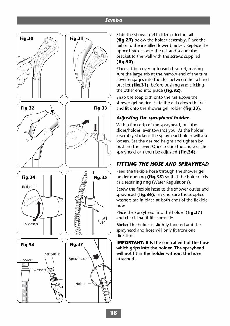
Slide the shower gel holder onto the rail(fig.29) below the holder assembly. Place therail onto the installed lower bracket. Replace theupper bracket onto the rail and secure thebracket to the wall with the screws supplied(fig.30).
Place a trim cover onto each bracket, makingsure the large tab at the narrow end of the trimcover engages into the slot between the rail andbracket (fig.31), before pushing and clickingthe other end into place (fig.32).
Snap the soap dish onto the rail above theshower gel holder. Slide the dish down the railand fit onto the shower gel holder (fig.33).
Adjusting the sprayhead holderWith a firm grip of the sprayhead, pull theslider/holder lever towards you. As the holderassembly slackens the sprayhead holder will alsoloosen. Set the desired height and tighten bypushing the lever. Once secure the angle of thesprayhead can then be adjusted (fig.34).
FITTING THE HOSE AND SPRAYHEADFeed the flexible hose through the shower gelholder opening (fig.35) so that the holder actsas a retaining ring (Water Regulations).
Screw the flexible hose to the shower outlet andsprayhead (fig.36), making sure the suppliedwashers are in place at both ends of the flexiblehose.
Place the sprayhead into the holder (fig.37)and check that it fits correctly.
Note: The holder is slightly tapered and thesprayhead and hose will only fit from onedirection.
IMPORTANT: It is the conical end of the hosewhich grips into the holder. The sprayheadwill not fit in the holder without the hoseattached.
Fig.31
Fig.32
Fig.30
Fig.34
Sprayhead
Holder
Washers
Shower
Sprayhead
Fig.36 Fig.29
Fig.33
Fig.37
Fig.35
Sprayhead
’O’ ring
Sprayplate
Bezel
Samba
19
CLEANING
Before cleaning, turn off the unit at theisolation switch to avoid the shower beingaccidentally switched on.
IT IS IMPORTANT TO KEEP THE SPRAYHEADCLEAN TO MAINTAIN THE PERFORMANCE OFTHE SHOWER. The hardness of the water willdetermine the frequency of cleaning. Forexample, if the shower is used every day in avery hard water area, it may be necessary toclean the sprayhead on a weekly basis.
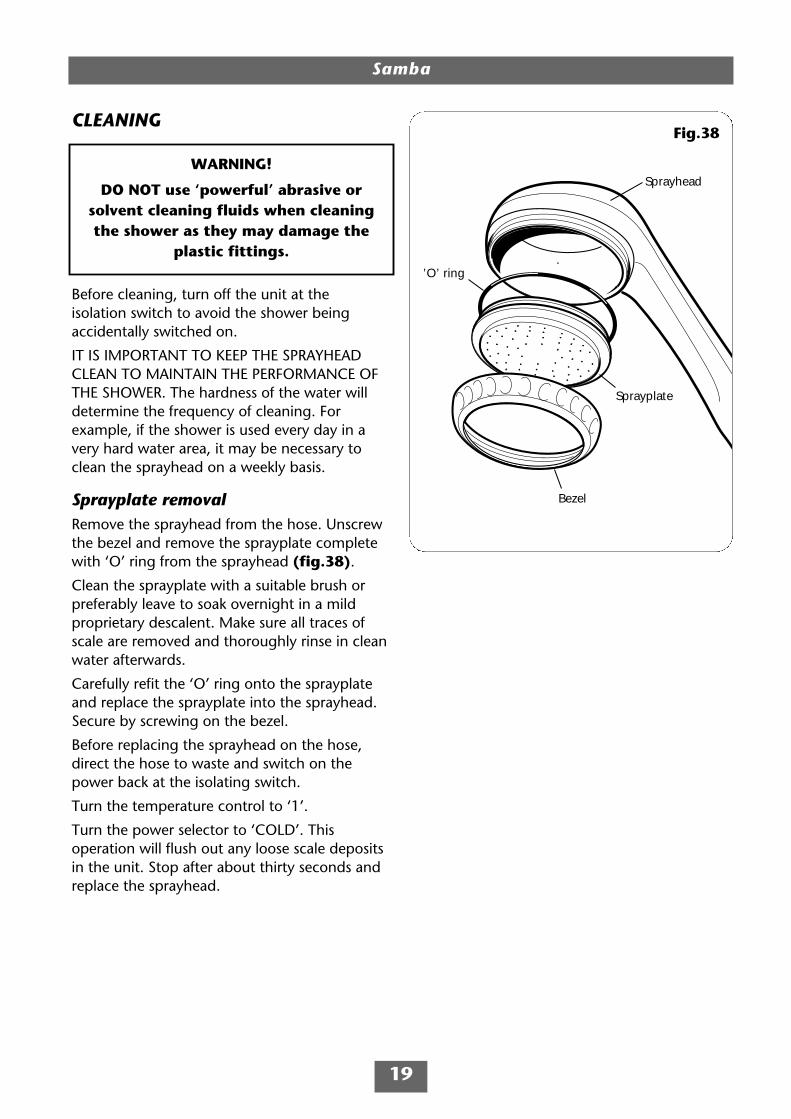
Sprayplate removalRemove the sprayhead from the hose. Unscrewthe bezel and remove the sprayplate completewith ‘O’ ring from the sprayhead (fig.38).
Clean the sprayplate with a suitable brush orpreferably leave to soak overnight in a mildproprietary descalent. Make sure all traces ofscale are removed and thoroughly rinse in cleanwater afterwards.
Carefully refit the ‘O’ ring onto the sprayplateand replace the sprayplate into the sprayhead.Secure by screwing on the bezel.
Before replacing the sprayhead on the hose,direct the hose to waste and switch on thepower back at the isolating switch.
Turn the temperature control to ‘1’.
Turn the power selector to ‘COLD’. Thisoperation will flush out any loose scale depositsin the unit. Stop after about thirty seconds andreplace the sprayhead.
WARNING!
DO NOT use ‘powerful’ abrasive orsolvent cleaning fluids when cleaningthe shower as they may damage the
plastic fittings.
Fig.38
Samba
20
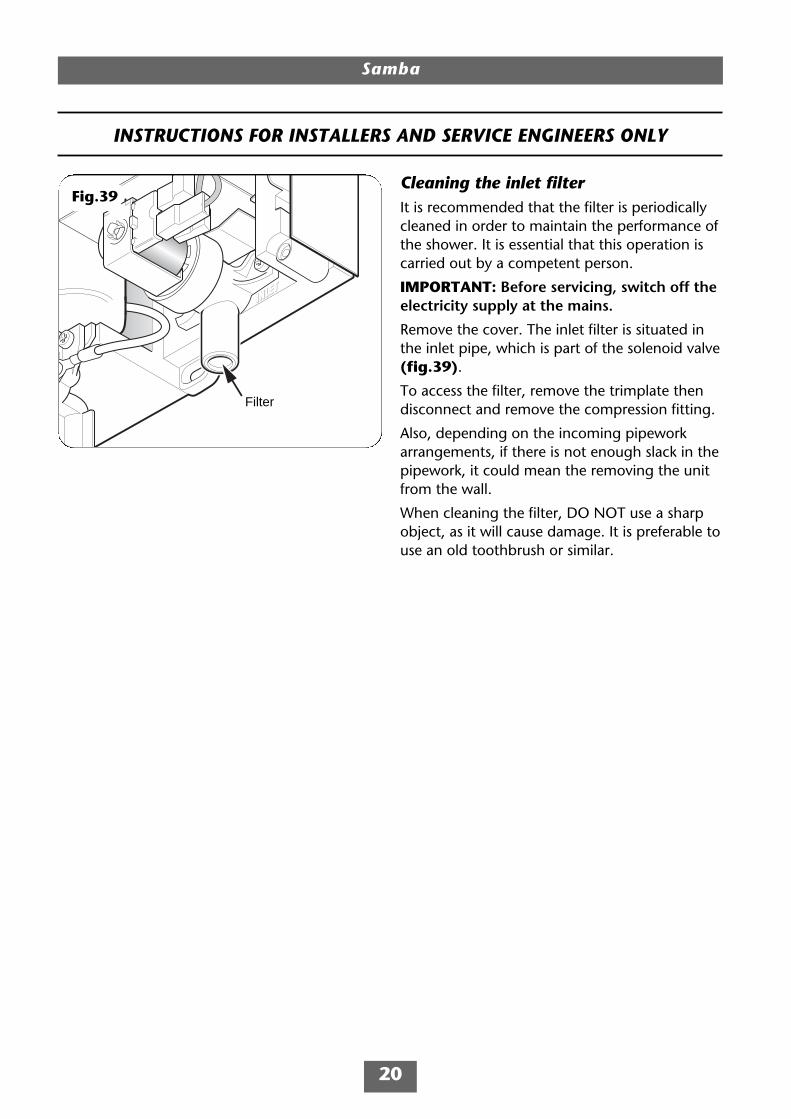
Cleaning the inlet filterIt is recommended that the filter is periodicallycleaned in order to maintain the performance ofthe shower. It is essential that this operation iscarried out by a competent person.
IMPORTANT: Before servicing, switch off theelectricity supply at the mains.
Remove the cover. The inlet filter is situated inthe inlet pipe, which is part of the solenoid valve(fig.39).
To access the filter, remove the trimplate thendisconnect and remove the compression fitting.
Also, depending on the incoming pipeworkarrangements, if there is not enough slack in thepipework, it could mean the removing the unitfrom the wall.
When cleaning the filter, DO NOT use a sharpobject, as it will cause damage. It is preferable touse an old toothbrush or similar.
Filter
Fig.39
INSTRUCTIONS FOR INSTALLERS AND SERVICE ENGINEERS ONLY
12
3
4
5
6
8
79
Samba
21
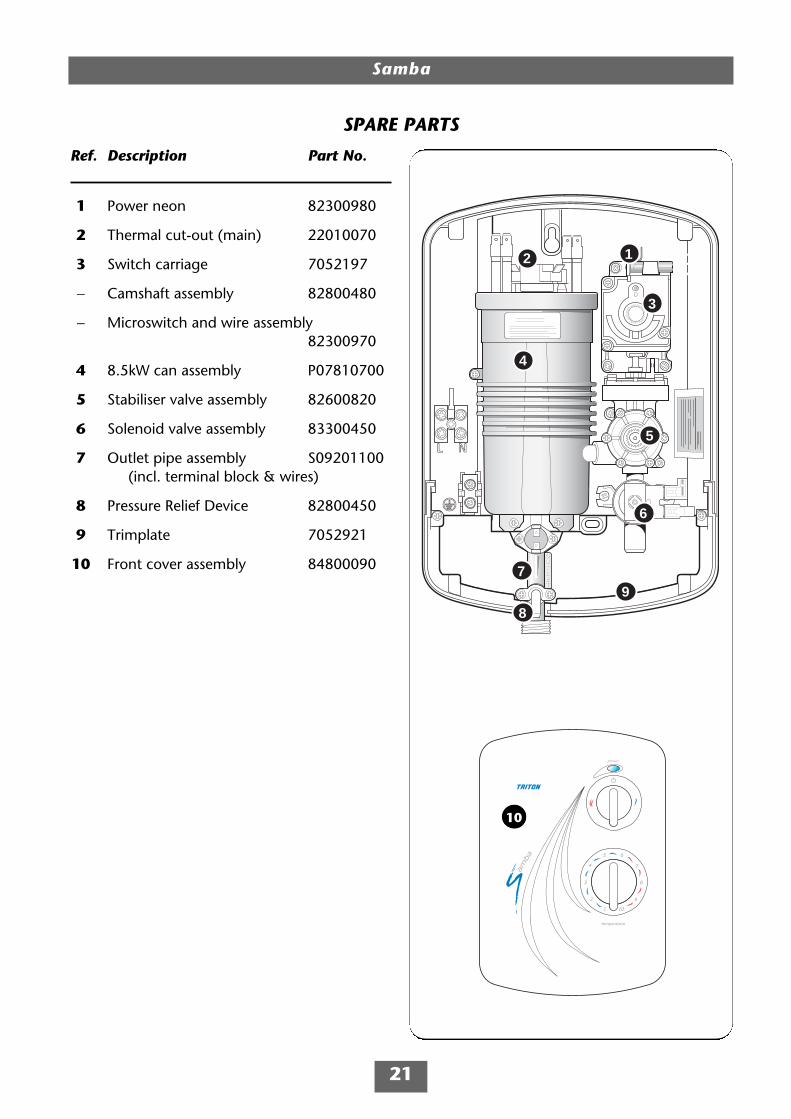
SPARE PARTS
Ref. Description Part No.
1 Power neon 82300980
2 Thermal cut-out (main) 22010070
3 Switch carriage 7052197
− Camshaft assembly 82800480
− Microswitch and wire assembly82300970
4 8.5kW can assembly P07810700
5 Stabiliser valve assembly 82600820
6 Solenoid valve assembly 83300450
7 Outlet pipe assembly S09201100(incl. terminal block & wires)
8 Pressure Relief Device 82800450
9 Trimplate 7052921
10 Front cover assembly 84800090
10

Samba
22
SPARE PARTS
Ref. Description Part No.
11 Pipe trim (backplate/trimplate) 7052920
12 Sprayhead 22004600
13 Brackets (pair) 22010700
14 Riser rail − white 7042411
15 Sprayhead holder 22010690
16 Soap dish 22006840
17 Gel hanger 22006850
18 Flexible hose – white 28100070
11
12
13
14
15
16
17
18
Samba
23
1 Showerinoperable, nowater flow.
2 Water too hot.
3 Watertemperature cyclinghot/cool atintervals.
4 Water too coolor cold.
1.1 Interrupted powersupply.
1.2 Unit malfunction.
2.1 Not enough waterflowing through theshower.
2.2 Blockage in supply.
2.3 Increase in ambientwater temperature.
3.1 Heater cycling ontemperature limiter.
4.1 Too much flow.
4.2 Water pressurebelow minimum required(see rating label).
4.3 Reduction inambient watertemperature.
4.4 Electricalmalfunction.
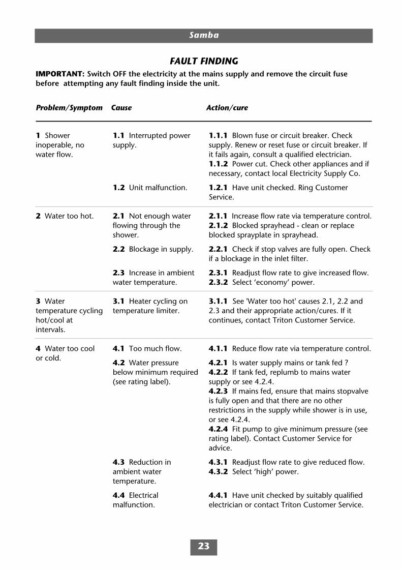
1.1.1 Blown fuse or circuit breaker. Checksupply. Renew or reset fuse or circuit breaker. Ifit fails again, consult a qualified electrician.1.1.2 Power cut. Check other appliances and ifnecessary, contact local Electricity Supply Co.
1.2.1 Have unit checked. Ring CustomerService.
2.1.1 Increase flow rate via temperature control.2.1.2 Blocked sprayhead - clean or replaceblocked sprayplate in sprayhead.
2.2.1 Check if stop valves are fully open. Checkif a blockage in the inlet filter.
2.3.1 Readjust flow rate to give increased flow.2.3.2 Select ‘economy’ power.
3.1.1 See 'Water too hot' causes 2.1, 2.2 and2.3 and their appropriate action/cures. If itcontinues, contact Triton Customer Service.
4.1.1 Reduce flow rate via temperature control.
4.2.1 Is water supply mains or tank fed ?4.2.2 If tank fed, replumb to mains watersupply or see 4.2.4.4.2.3 If mains fed, ensure that mains stopvalveis fully open and that there are no otherrestrictions in the supply while shower is in use,or see 4.2.4.4.2.4 Fit pump to give minimum pressure (seerating label). Contact Customer Service foradvice.
4.3.1 Readjust flow rate to give reduced flow.4.3.2 Select ‘high’ power.
4.4.1 Have unit checked by suitably qualifiedelectrician or contact Triton Customer Service.
FAULT FINDINGIMPORTANT: Switch OFF the electricity at the mains supply and remove the circuit fusebefore attempting any fault finding inside the unit.
Problem/Symptom Cause Action/cure

5 Shower variesfrom normaltemperature to coldduring use.
6 Pressure reliefdevice has operated(water ejected fromPRD tube).
7. Shower fails toshut off.
4.5 Safety cut-outoperated.
5.1 Water pressure hasdropped belowminimum required.
6.1 Blocked sprayhead.
6.2 Twisted/blockedflexible shower hose.
6.3 Sprayhead notremoved whilecommissioning.
7.1 Faulty microswitch.
7.2 Debris in thesolenoid.
4.5.1 The thermal safety cut-out device hasoperated. Have the unit checked by a suitablyqualified service engineer or contact CustomerService.
5.1.1 Wait until the water pressure resumes tonormal.
6.1.1 Clean or replace blocked sprayplate insprayhead and then fit new PRD.
6.2.1 Check for free passage through hose.Replace the hose if necessary and fit new PRD.
6.3.1 Fit new PRD. Commission unit withsprayhead removed.
7.1.1 Replace microswitch.
7.2.1 Replace solenoid valve.
FAULT FINDING
Problem/Symptom Cause Action/cure
In the unlikely event of unit failure other than detailed in the fault finding page,please contact Customer Service for advice.
Note: Identify the cause of operation before fitting a new PRD unit. When fittinga new PRD, follow the commissioning procedure.
It is advised all electrical maintenance/repairs to the showershould be carried out by a suitably qualified person.
Samba
24

Samba
25

Service PolicyIn the event of a complaint occurring, thefollowing procedure should be followed:1 Telephone Customer Service on +44 (0) 247637 2222 (+44 (0) 84 5762 6591 in Scotlandand in Northern Ireland), having available themodel number and power rating of the product,together with the date of purchase.2 Triton Customer Service will be able to confirmwhether the fault can be rectified by either theprovision of a replacement part or a site visit froma qualified Triton service engineer.3 If a service call is required it will be booked andthe date of call confirmed. In order to expediteyour request, please have your postcode availablewhen booking a service call.4 It is essential that you or an appointedrepresentative (who must be a person of 18 yearsof age or more) is present during the serviceengineer's visit and receipt of purchase is shown.5 A charge will be made in the event of anaborted service call by you but not by us, orwhere a call under the terms of guarantee hasbeen booked and the failure is not product related(i.e. scaling and furring, incorrect water pressure,pressure relief device operation, electricalinstallation faults). 6 If the product is no longer covered by theguarantee, a charge will be made for the site visitand for any parts supplied.7 Service charges are based on the account beingsettled when work is complete, the engineer willthen request payment for the invoice. If this is notmade to the service engineer or settled within tenworking days, an administration charge will beadded.
Replacement Parts PolicyAvailability: It is the policy of Triton to maintainavailability of parts for the current range ofproducts for supply after the guarantee hasexpired. Stocks of spare parts will be maintainedfor the duration of the product’s manufacture andfor a period of five years thereafter.In the event of a spare part not being available asubstitute part will be supplied.Payment: The following payment methods can beused to obtain spare parts:1 By post, pre-payment of pro forma invoice bycheque or money order.2 By telephone, quoting credit card (MasterCardor Visa) details.3 By website order, www.tritonshowers.co.uk
TRITON STANDARD GUARANTEETriton Plc guarantee this product against allmechanical and electrical defects arising fromfaulty workmanship or materials for a period oftwo years for domestic use only, from the date ofpurchase, provided that it has been installed by acompetent person in full accordance with thefitting instructions.Any part found to be defective during thisguarantee period we undertake to repair orreplace at our option without charge so long asit has been properly maintained and operated inaccordance with the operating instructions, andhas not been subject to misuse or damage.This product must not be taken apart, modifiedor repaired except by a person authorised byTriton Plc. This guarantee applies only toproducts installed within the United Kingdomand does not apply to products usedcommercially. This guarantee does not affectyour statutory rights.
What is not covered:1 Breakdown due to: a) use other thandomestic use by you or your resident family; b) wilful act or neglect; c) any malfunctionresulting from the incorrect use or quality ofelectricity, gas or water or incorrect setting ofcontrols; d) faulty installation.2 Repair costs for damage caused by foreignobjects or substances.3 Total loss of the product due to non-availability of parts.4 Compensation for loss of use of the productor consequential loss of any kind.5 Call out charges where no fault has beenfound with the appliance.6 The cost of repair or replacement of pressurerelief devices, sprayheads, hoses, riser railsand/or wall brackets, isolating switches, electricalcable, fuses and/or circuit breakers or any otheraccessories installed at the same time.7 The cost of routine maintenance,adjustments, overhaul modifications or loss ordamage arising therefrom, including the cost ofrepairing damage, breakdown, malfunctioncaused by corrosion, furring, pipe scaling,limescale, system debris or frost.
Triton PlcShepperton ParkCaldwell RoadNuneatonWarwickshire CV11 4NR
Customer Service: +44 (0) 24 7637 2222
Scottish and Northern IrelandCustomer Service: +44 (0) 84 5762 6591
Trade Installer Hotline: +44 (0) 24 7632 5491Fax: +44 (0) 24 7632 4564
www.tritonshowers.co.uk
E mail: [email protected]