sampling phased array a new technique for signal ... · pdf filesampling phased array a new...
TRANSCRIPT

Sampling Phased Array A New Technique for Signal Processing and Ultrasonic Imaging
Ludwig von BERNUS, QNET Engineering , Saarbrücken, Germany Аndrey BULAVINOV, Dieter JONEIT, Мichael KRÖNING, Fraunhofer Institute
Nondestructive Testing, Saarbrücken/Dresden, Germany Michael DALICHOV, Quality Network, USA
Кrishna Мohan REDDY, Quality Network Pvt. Ltd., Chennai, India
Abstract. Different signal processing and image reconstruction techniques are applied in ultrasonic non-destructive material evaluation. In recent years, rapid development in the fields of microelectronics and computer engineering lead to wide application of phased array systems. A new phased array technique, called “Sampling Phased Array” has been developed in Fraunhofer Institute for non-destructive testing. It realizes unique approach of measurement and processing of ultrasonic signals. The sampling phased array principle make use of the measurement of elementary waves generated by individual elements of sensor array to reconstruct the composite phased array signal for any arbitrary angle or focus depth. The use of special signal processing and image reconstruction algorithms, allows generating A-Scans of several angles and / or Sector-Scan, which can be implemented in real time. With parallel computing structures, this principle is used for automatic testing systems at very high inspection speed. A comparative study was done with Conventional Phased Array system and Sampling Phased Array technique. The study shows that the signal characteristics in both techniques are equal. In addition, the Sampling Phased Array technique is significantly beneficial in the many aspects like quality of information in specific cases, inspection speeds and adaptability to specific inspection tasks in comparison to conventional Phased Array. The electronics was developed as a development platform for high speed automated ultrasonic inspection systems for process integrated testing and also for testing of critical components. The development results, including relevant test methodology and electro-technical/electronic aspects are presented in the current work.
Introduction In the field of nondestructive testing, conventional manual ultrasonic testing techniques are increasingly being replaced by automated ultrasonic inspection systems. The availability of economically priced and powerful micro-electronic and computer components is driving this investment in ultrasonic Phased Array systems [1].
A phased array system is a multi channel ultrasonic system, which uses the principle of a time-delayed triggering of the transmitting transducer elements, combined with a time corrected receiving of detected signals. The main advantage of the phased array systems is their ability to vary the angle of insonification in the inspection object (sweeping and focusing
ECNDT 2006 - We.3.1.2
1
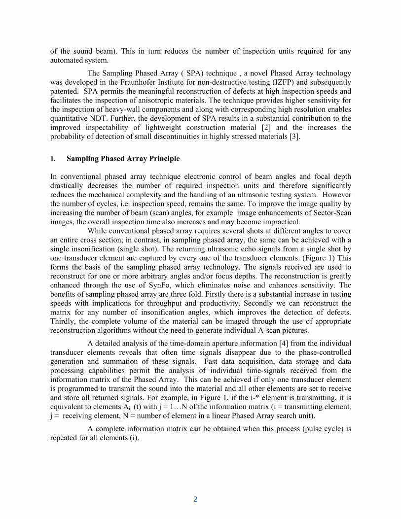
of the sound beam). This in turn reduces the number of inspection units required for any automated system.
The Sampling Phased Array ( SPA) technique , a novel Phased Array technology was developed in the Fraunhofer Institute for non-destructive testing (IZFP) and subsequently patented. SPA permits the meaningful reconstruction of defects at high inspection speeds and facilitates the inspection of anisotropic materials. The technique provides higher sensitivity for the inspection of heavy-wall components and along with corresponding high resolution enables quantitative NDT. Further, the development of SPA results in a substantial contribution to the improved inspectability of lightweight construction material [2] and the increases the probability of detection of small discontinuities in highly stressed materials [3].
1. Sampling Phased Array Principle In conventional phased array technique electronic control of beam angles and focal depth drastically decreases the number of required inspection units and therefore significantly reduces the mechanical complexity and the handling of an ultrasonic testing system. However the number of cycles, i.e. inspection speed, remains the same. To improve the image quality by increasing the number of beam (scan) angles, for example image enhancements of Sector-Scan images, the overall inspection time also increases and may become impractical.
While conventional phased array requires several shots at different angles to cover an entire cross section; in contrast, in sampling phased array, the same can be achieved with a single insonification (single shot). The returning ultrasonic echo signals from a single shot by one transducer element are captured by every one of the transducer elements. (Figure 1) This forms the basis of the sampling phased array technology. The signals received are used to reconstruct for one or more arbitrary angles and/or focus depths. The reconstruction is greatly enhanced through the use of SynFo, which eliminates noise and enhances sensitivity. The benefits of sampling phased array are three fold. Firstly there is a substantial increase in testing speeds with implications for throughput and productivity. Secondly we can reconstruct the matrix for any number of insonification angles, which improves the detection of defects. Thirdly, the complete volume of the material can be imaged through the use of appropriate reconstruction algorithms without the need to generate individual A-scan pictures.
A detailed analysis of the time-domain aperture information [4] from the individual transducer elements reveals that often time signals disappear due to the phase-controlled generation and summation of these signals. Fast data acquisition, data storage and data processing capabilities permit the analysis of individual time-signals received from the information matrix of the Phased Array. This can be achieved if only one transducer element is programmed to transmit the sound into the material and all other elements are set to receive and store all returned signals. For example, in Figure 1, if the i-* element is transmitting, it is equivalent to elements Aij (t) with j = 1…N of the information matrix (i = transmitting element, j = receiving element, N = number of element in a linear Phased Array search unit).
A complete information matrix can be obtained when this process (pulse cycle) is repeated for all elements (i).
2

By virtue of the reciprocity of transmitter and receiver, Aij equals Aji (Aij = Aji). The diagonal elements Aii (i = 1, N) correspond to the information from element “i”, scanning the entire search unit aperture similar to the image reconstruction based on the SAFT (Synthetic Aperture Focusing Technique) principle [5].
Of particular interest is the fact that each individual transmission row (i) in the information matrix contains the entire array of all transducer elements of the selected receiving group. Irrespective of sound field interactions with potentially strong interference signals, a single information matrix row contains all essential information required to produce a reconstructed image. In other words, a single transmission cycle can provide a complete reconstructed image. Signal to noise ratio issues and the detection of planar flaws with distinct directivity patterns can be avoided due to the simultaneous transmission of all elements combined into a virtual point source or linear source [6, 7, 8].
This approach allows a complete sector-scan reconstruction with any scan (beam) angle and at arbitrary focal points for each transmission cycle. Suitable real-time signal processing methods are available today for integrated highly-efficient parallel computing [9].
2. UT Data Reconstruction Virtual A-Scan presentations can be produced from the time-signals (Aij) by considering relevant phase relationships. From the physical perspective the computed A-Scans should be equivalent to conventionally produced A-Scans assuming that the discontinuity is not insonified by a unidirectional soundbeam. The complete sound field is virtually composed by the processor and not the conventional way (analog) when collected from individual transducer element wave portions. The presence of heavy non-linear test conditions would impose a limitation to this technique.
The reconstruction capability of A-Scan images is of utmost importance for the Sampling Phased Array technique to comply with existing Codes, Standards and Regulations for NDT.
B-Scan, C-Scan and Sector-Scan images can be produced in an almost the same way as in conventional Phased Array from any of the acquired A-Scans with various scan (beam) angles and individually selectable focal length.
A11 A12 A13 A14
A21 A22 A23 A24
A31 A32 A33 A34
A41 A42 A43 A44
... 1 2 3 4
∑ Aij⋅ f(φk)
Figure 1: Information Matrix of a 4-Element Phased Array Search Unit
3
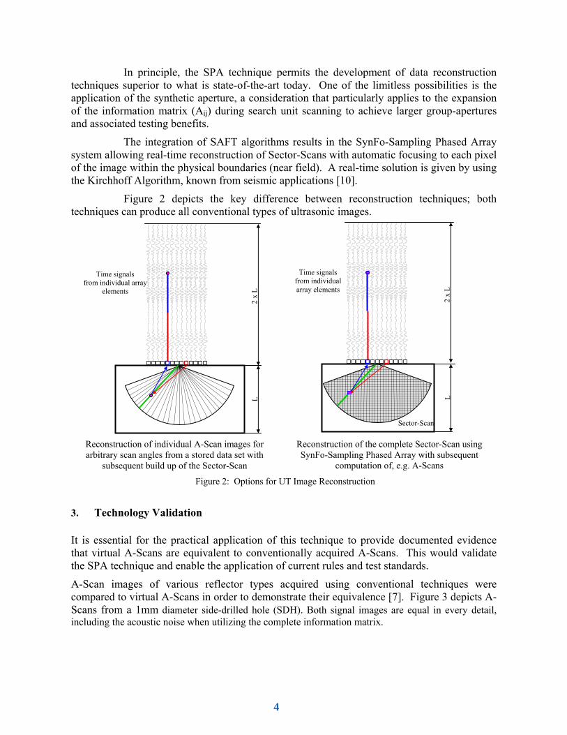
In principle, the SPA technique permits the development of data reconstruction techniques superior to what is state-of-the-art today. One of the limitless possibilities is the application of the synthetic aperture, a consideration that particularly applies to the expansion of the information matrix (Aij) during search unit scanning to achieve larger group-apertures and associated testing benefits.
The integration of SAFT algorithms results in the SynFo-Sampling Phased Array system allowing real-time reconstruction of Sector-Scans with automatic focusing to each pixel of the image within the physical boundaries (near field). A real-time solution is given by using the Kirchhoff Algorithm, known from seismic applications [10].
Figure 2 depicts the key difference between reconstruction techniques; both techniques can produce all conventional types of ultrasonic images.
3. Technology Validation It is essential for the practical application of this technique to provide documented evidence that virtual A-Scans are equivalent to conventionally acquired A-Scans. This would validate the SPA technique and enable the application of current rules and test standards.
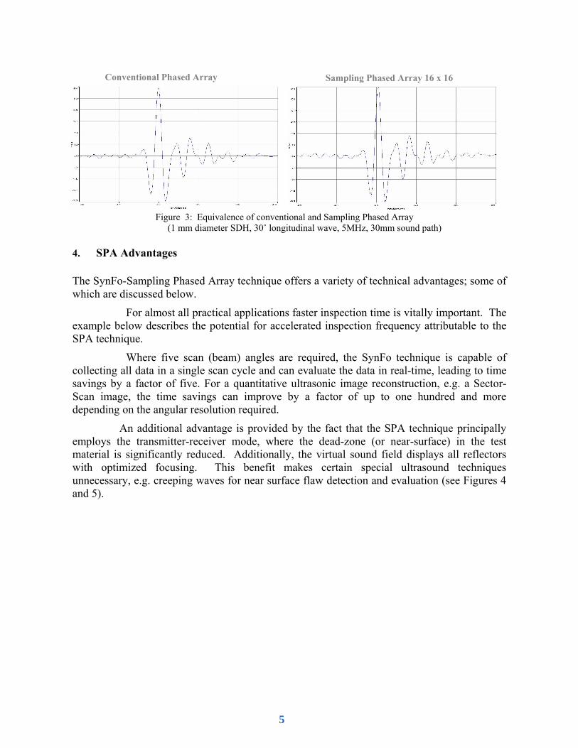
A-Scan images of various reflector types acquired using conventional techniques were compared to virtual A-Scans in order to demonstrate their equivalence [7]. Figure 3 depicts A-Scans from a 1mm diameter side-drilled hole (SDH). Both signal images are equal in every detail, including the acoustic noise when utilizing the complete information matrix.
L 2
x L
Time signals from individual array
elements
Reconstruction of individual A-Scan images for arbitrary scan angles from a stored data set with
subsequent build up of the Sector-Scan
Reconstruction of the complete Sector-Scan using SynFo-Sampling Phased Array with subsequent
computation of, e.g. A-Scans
Sector-Scan
L 2
x L
Time signals from individual array elements
Figure 2: Options for UT Image Reconstruction
4
4. SPA Advantages The SynFo-Sampling Phased Array technique offers a variety of technical advantages; some of which are discussed below.
For almost all practical applications faster inspection time is vitally important. The example below describes the potential for accelerated inspection frequency attributable to the SPA technique.
Where five scan (beam) angles are required, the SynFo technique is capable of collecting all data in a single scan cycle and can evaluate the data in real-time, leading to time savings by a factor of five. For a quantitative ultrasonic image reconstruction, e.g. a Sector-Scan image, the time savings can improve by a factor of up to one hundred and more depending on the angular resolution required.
An additional advantage is provided by the fact that the SPA technique principally employs the transmitter-receiver mode, where the dead-zone (or near-surface) in the test material is significantly reduced. Additionally, the virtual sound field displays all reflectors with optimized focusing. This benefit makes certain special ultrasound techniques unnecessary, e.g. creeping waves for near surface flaw detection and evaluation (see Figures 4 and 5).
Conventional Phased Array Sampling Phased Array 16 x 16
Figure 3: Equivalence of conventional and Sampling Phased Array (1 mm diameter SDH, 30˚ longitudinal wave, 5MHz, 30mm sound path)
5

Figure 4: Comparison of conventional Phased Array with SynFo-Sampling Phased Array for near-surface reflectors
b) Conventional Phased Array 3mm focal depth
Initial pulse
a) Conventional Phased Array w/o focusing
Initial pulse
BW Signal from 2. reflector
c) SynFo-Sampling Phased Array Mode
BW
Signal from 1. reflector
Signal from 2. reflector
1
2
6

a) Conventional Phased Array
Backwall
SDH 2SDH 3
SDH 4
b) Conventional Phased Array
5mm focal depth SDH 3
SDH 3
c) SynFo-Sampling Phased Array Mode
Backwall
SDH 1SDH 2
SDH 4
Figure 5: Test data from the near field, conventional Phased Array vs. Sampling Phased Array
1 23
4
1 23
4
7

5. New Solutions to Existing Testing Problems Besides the improvement of test speed with concurrent quantitative ultrasonic images, Sampling Phased Array provides innovative testing solutions that cannot be achieved with existing conventional techniques. Three examples are discussed below.
5.1 Quantitative Imaging in High-Speed Steel Section UT The deployment of conventional Phased Array systems for high-speed product line-integrated industrial applications, e.g. testing of steel bars and billets, is limited to processes with relatively long cycle times. The Sampling Phased Array technology allows that all scan (beam) angles are activated and processed simultaneously in one single scan cycle. This means that the SPA technique significantly improves the information content of ultrasonic test results at very high speeds.
The test results can be evaluated in accordance with existing standards and procedures, for example A-Scan images using the DGS method, or by using real-time reconstruction analysis of two-dimensional B-Scans (Figure 6).
The image reconstruction algorithm principally tolerates infractions of the Sampling Theorem, which provides the basis for the Sampling Phased Array technique. Thus, standard transducers, optimally arranged around the test object, may be employed. We called this procedure the TOMO-SAFT technique.
A-Scan at 0˚ Scan Angle, Immersion Technique
Initial Pulse BW Entry Signal 2.E
FBH 1
∅1 ∅1 ∅1
∅1 ∅1
Conventional Phased Array
Sampling Phased Array
Figure 6: Potential of fast quantitative imaging of billet UT.
8

5.2 Inspection of Acoustically Anisotropic Materials The wave fronts of elementary waves in isotropic materials are spherical and the sound propagates in perpendicular direction to the wave front. In anisotropic materials, the wave fronts are non-spherical and the sound field is rather distorted [11].
Elementary wave phase conditions and relations, assessable with SPA, can be adjusted (considering the anisotropy of the material) to a quasi-normal test condition of anisotropic materials. The pixel-to-element transit time can be derived from the stiffness matrix or from experimentally obtained directional sound velocities. This technique is identified as “Reverse Phase Matching” [12].
State-of-the-art algorithms are used to calculate the sound wave propagation [13]. Figure 7 depicts ultrasonic testing results obtained from a composite carbon-fiber sample.
The Reverse Phase Matching technique offers the following advantages:
1. The SPA technique in the Reverse Phase Matching mode permits flaw detection and image reconstruction in anisotropic materials.
2. This technique allows the characterization of anisotropic materials by using calculative variations of structural assumptions.
3. The number of transmitting elements, the displacement and the arrangement of the inspection system can be adjusted to meet the requirements of the anisotropic structure of the test sample
As the inspection is performed using the immersion technique, considered to be an inspection of heterogeneous materials, complicated surface configurations will not require elaborate adjustments to the transducer elements. This leads to significant resource savings during system setup and also reduces the costs involved in the design and manufacture of inspection systems and assemblies.
Phased Array search unit on a sample with artificial reflectors
Artificial Flaw ∅ 3mm
Backwall
Conventional Phased Array
Backwall
Artificial Flaw ∅ 3mm
SPA with Inverse Phase Matching
Figure 7: Ultrasonic inspection of carbon-fiber materials; obvious benefits of Sampling Phased Array with Inverse Phase Matching
9

5.3 Ultrasonic Inspection of Heavy-Wall Components Ultrasonic inspection of heavy-wall components, such as turbine shafts, are usually very time consuming as the long travel paths require relatively low pulse repetition rates. An additional problem associated with long travel paths is the poor resolution of flaw reflectors and thus the characterization of discontinuities in compliance with high detection sensitivity. Conventional Phased Array techniques currently in use cannot overcome this type of physical limitation. The complete inspection of a large turbine shaft (up to 1.5 meters in diameter) using conventional Phased Array may take several days to complete and thus significantly impacts the production schedule.
The application of the SPA technique allows the implementation of several scan (beam) angles with a single transmission cycle. However, an insufficient S/N ratio (another side-effect of long travel paths) caused by the energy transmitted in each cycle must be expected; the transmitter energy, even during defocused transmitting with all transducer elements (used to increase the sensitivity through the emulation of a point source transmitter), is insufficient to result in adequate S/N ratios. In theory, the aperture of the Phased Array search unit has to be increased to achieve the desired S/N ratio, which would lead to a large sized inspection system and lower reflector resolutions when conventional Phased Array techniques are used.
Utilizing a synthetic aperture while scanning the test object can resolve the above described difficulties. The ultrasonic signals received from each individual transducer element at different locations are synthetically reconstructed for all scan (beam) angles; this approach provides the following advantages:
1. The SPA only fires one shot (cycle) at each scan position, where conventional Phased Array requires multiple cycles, depending on the number of scan angles. For example: a turbine shaft inspection with conventional Phased Array involves nine scan angles (0°, ±7°, ±14°, ±21° and ±28°) and therefore nine shots, whereas the SPA technique fires only one shot resulting in a speed improvement by a factor of nine.
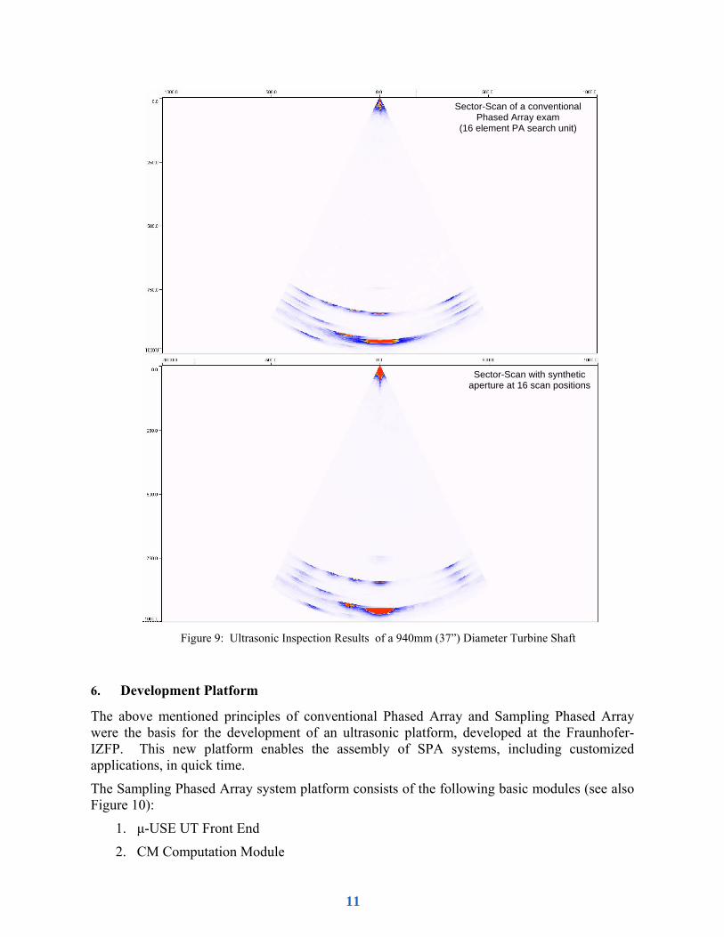
2. At equal or better testing sensitivity (depending on the size of the available synthetic aperture) the synthetic aperture technique permits a better resolution given by the effect of the element aperture, as illustrated in Figures 8 and 9.
A test sample (turbine shaft with 3mm diameter side-drilled-holes, Figure 8) was inspected with conventional and SPA techniques. Even with relatively small apertures (16 positions at 1.8mm distance) the Sampling Phased Array technique achieves the same test sensitivity and S/N ratio as the conventional Phased Array technique. The SPA technique provides a far better angular resolution (Figure 9). The synthetic aperture in this example is double the size the aperture of a conventional 16 element Phased Array search unit.
21˚
14˚
7˚ 0˚
21˚
Figure 8: Test sample for ultrasonic inspection of turbine shafts
10
6. Development Platform
The above mentioned principles of conventional Phased Array and Sampling Phased Array were the basis for the development of an ultrasonic platform, developed at the Fraunhofer-IZFP. This new platform enables the assembly of SPA systems, including customized applications, in quick time.
The Sampling Phased Array system platform consists of the following basic modules (see also Figure 10):
1. μ-USE UT Front End
2. CM Computation Module
Sector-Scan of a conventional Phased Array exam
(16 element PA search unit)
Sector-Scan with synthetic aperture at 16 scan positions
Figure 9: Ultrasonic Inspection Results of a 940mm (37”) Diameter Turbine Shaft
11

3. CM Interface: Transceiver (optical link to internal bus)
4. Coordinate Interface
5. Master PC w/ PCI-bus for up to four CM modules
6. Control Software and Data Acquisition/Analysis Software
The μ-USE Ultrasonic front end is a ultrasonic module featuring 16 completely independent (parallel) ultrasonic channels, and is expandable to 32 or 64 channels; this front end can also be used for conventional multi-channel applications. The UT front end is based on cutting-edge micro-electronic components and satisfies even the most advanced UT test equipment requirements [14] in a very compact design (Figure 10, Top).
The CM computation module (Figure 10, Bottom) has been developed for fast data processing using parallel computer architectures. All necessary data and image reconstruction algorithms are incorporated into the CM module.
Additional modules, such as CPU interface, coordinates interface, etc., are inexpensive commercially available components of the UT system platform.
7. Summary
The Sampling Phased Array technology enables new approaches and opportunities for the development and application of ultrasonic test systems.
IZFP has provided a development platform with the following advantages (compared to conventional techniques):
1. Increase of test speed as well as improved resolution with product line integration options enabling test speeds of several meters per second.
2. Quantitative imaging in real-time
μ-USE 16 to 64 Channels
CM Interface
ComputationModule
μ-USE 16 to 64 Channels
CM Interface
μ-USE 16 to 64 Channels
CM Interface
Serial optical link
μ-USE 16 to 64 Channels
CM Interface
Serial optical link
PCI-Bus
c l o c k
Trigger (+ Coordinate)
Driver coordinate board
Driver CM
μ-USE driver Interface
Application Software
ComputationModule
ComputationModule
ComputationModule
16-Channel μ-USE UT Front End
Multi-DSP Computation Module
Coordinate Interface
Figure 10: SPA Ultrasonic Platform
Serial optical link
Serial optical link
12
3. Enhances the ability of Ultra Sound Systems to inspect materials which have poor Inspectability, e.g. non-homogeneous anisotropic materials (carbon fiber, stainless steel, dissimilar welds)
4. Economically priced electronic components based on latest micro-electronic technology which significantly lowers the investment required to build automated inspection systems.
5. Compliance with national and international standards, codes and regulations
References
[1] H. Wüstenberg, G. Schenk, Entwicklungen und Trends bei der Anwendung von steuerbaren Schallfeldern in der ZfP mit Ultraschall, Mainz, DGZfP-Jahrestagung 2003
[2] J. Klenner: Werkstoffvisionen im Verkehrsflugzeugbau, Konferenz „Werkstoffinnovationen für Industrie und Gesellschaft“, Weimar, 29. – 31. Oktober 2003
[3] P. Ciorau: A Contribution to Detecting and Sizing Linear Defects by Phased Array Ultrasonic Techniques, 4th International Conference on NDE in Relation to Structural Integrity for Nuclear and Pressurised Components, London, 6-8 December 2004
[4] R.Y. Chiao, L.J. Thomas: Analytic Evaluation of Sampled Aperture Ultrasonic Imaging Techniques for NDE, IEEE Transactions on Ultrasonics, Ferroelectrics and Frequency control, Vol. 41, No.4, July 1994
[5] W. Müller, V. Schmitz, G. Schäfer, Reconstruction by the Synthetic Aperture Focusing Technique. Nuclear Engineering and Design, 1988, pp. 393 –404
[6] Kröning M., Hentschel D., von Bernus L., Bulavinov A., Reddy K. M.; Deutsche Patentanmeldung Nr. 10 2004 059 856.8, Verfahren zur zerstörungsfreien Untersuchung eines Prüfkörpers mittels Ultraschall. Tag der Anmeldung: 10.12.2004
[7] Bulavinov A.: Der getaktete Gruppenstrahler. Saarbrücken 2005 (Dissertation).
[8] Kröning M., Bulavinov A., Reddy K. M., von Bernus L.: Deutsche Patentanmeldung Nr. 10 2005 051 781.1, Verfahren zur zerstörungsfreien Untersuchung eines Prüfkörpers mittels Ultraschall. Tag der Anmeldung: 28.10.2005
[9] Ananth Grama, Anshul Gupta, George Karypis, Vipin Kumar: Introduction to Parallel Computing, 2nd Edition, Addison-Wesley, Februar 2003
[10] Jon F. Claerbout, Cecil and Ida Green Professor of Stanford University, EARTH SOUNDINGS ANALYSIS: Processing versus Inversion, March 23, 2004
[11] P. Fellinger, R. Marklein, K. J. Langenberg, S. Klaholz, "Numerical modeling of elastic wave propagation and scattering with EFIT - elastodynamic finite integration technique", Wave Motion 21, 47-66, 1995
[12] Kröning M., Bulavinov A., Reddy K. M.: Deutsche Patentanmeldung Nr. 10 2006 003 978.5, Verfahren zur zerstörungsfreien Untersuchung eines wenigstens akustisch anisotropen Werkstoffbereich aufweisenden Prüfkörpers. Tag der Anmeldung: 27.01.2006
[13] J.D. Achenbach, Wave propagation in elastic solids, North-Holland, Elsevier, Amsterdam, 1984
[14] Zerstörungsfreie Prüfung - Charakterisierung und Verifizierung der Ultraschall-Prüfausrüstung; Deutsche Fassung EN 12668-1:2000
13