san jose state university - learning objectives:€¦ · web viewusb232485 install tutorial windows...
TRANSCRIPT

SmartMotor Laboratory 1 SMART-1
Introduction to the Moog-Animatics Smart MotorLearning Objectives:After successfully completing this lab, students will be able to:
Interact with the SmartMotor Interface (SMI) software to control a SmartMotor Explain the advantages of using a SmartMotor over putting together your own motion control solution
from disparate pieces Program a SmartMotor utilizing inputs from external I/O from the SmartMotor BCD controller
Components:Qty. Item1 CBLSM-DEMO1 Communications/Power Cable1 24 V DC Power Supply1 RS232-to-USB Adapter (RS232485TUSB)1 SMARTBOX-BCD interface unit1 SM2315D SmartMotor
Pre-Lab Tasks(The computers in the E135 laboratory should already be set up for this lab exercise, but if you wish to perform the lab using your own computer, follow steps 1 and 2 below)
1. (Follow this step ONLY if you are installing the software on your own computer) Download and in-stall the SMI software: http://www.animatics.com/products/smartmotor/animatics/host-software/smi-smartmotor-interface.html
2. (Follow this step ONLY if you are installing the software on your own computer) Download and in-stall the USB232485 drivers:
a. Go to the Download Center at: http://www.animatics.com/index.php?option=com_content&view=article&id=104&Itemid=9&dir=JSROOT%2Ftop+level%2F3.+SMI+Software+And+Drivers/USB+Driver
b. Download and follow the instructions in USB232485 Install Tutorial Windows 7-Windows Vista.pdf OR download the USB232485 Install notes.txt file and follow its directions, but note the following clarifications:
1) The first step should say to “plug in the KITUSB232485 USB-to-Serial Converter into your USB port”. When this is done, the PC will find a driver for the device. Af-ter a driver is found, now you can follow the first step listed in the Install Notes, which is to “unplug the USB-232 device”.
2) The next step should say to “go the Device Manager and uninstall the SmartMotor USB to Serial Converter” rather than Install/Uninstall Programs. You should see this driver listed under Other Devices.
3) Now you can follow steps 3 - 9 in the Install Notes
4) At step 10, look under the Ports (COM and LPT) list in the Device Manager. You should see ‘Standard port types’ in the left list box at the top of the list.
3. Review the SmartMotor Command Overview in the Animatics Institute Training Manual, 2008 (pp. 84-88). You can access the manual at: http://www.engr.sjsu.edu/bjfurman/courses/ME190/Lab_related/SmartMotor%20related/AnimaticsInstituteTrainingManual2008.pdf
©San José State University Mechanical Engineering rev. 1.0.3 10NOV2015

SmartMotor Laboratory 1 SMART-1
Introduction A Moog-Animatics SmartMotor is a motor that integrates the motion controller, drive amplifier, and feedback devices into a single package, creating a complete servo system. Most engineers who are not familiar with the SmartMotor typically start from scratch to build their own motion control system when tasked with designing an automated system. Such systems often use separate components consisting of a motion controller, a drive amplifier, the motor, and feedback devices. A motion control solution built in this piecemeal fashion can suffer from multiple problems that accrue in the non-trivial exercise of acquiring all the components and getting them all to work together to deliver the desired motion characteristics. Such problems include: higher system costs, higher rates of failure, slower time-to-market, and increased difficulty in troubleshooting or diagnosing performance problems. The Moog-Animatics SmartMotor eliminates the complexity and difficulties in designing a motion control solution by providing an all-in-one motion control -package. The integrated servo system reduces costs, because separate components do not need to be purchased and integrated by the end user. It decreases overall time-to-market, because separate components do not need to be sized and selected, and because motion control can be handled by the SmartMotor itself rather than by a separately programmed control device such as a microcontroller or programmable logic controller. The use of SmartMotors reduces the system’s complexity, therefore increasing its reliability and decreasing diagnostic and field repair costs.
In this lab, you will get an in-depth introduction to the SmartMotor, which is an important commercially available motion control solution. This knowledge will help you be more effective and productive in your professional career.
Exercises:
Exercise 1: Assemble the Class 4 SmartMotor Servo System.
Refer to the Figure 1 below for clarification of how to assemble the Class 4 SmartMotor servo system.
1. Plug in the USB-end of the KITUSBRS23248 USB-to-Serial Converter cable into the com-puter, and plug the male 9-pin RS232 end into the female 9-pin end of the CBLSM1-DEMO cable
2. Plug the green end of the CBLSM-DEMO1cable into the SmartMotor3. Plug the 24VDC power supply barrel adapter into the side of the CBLSM-DEMO1cable 4. Plug the Smart Box BCD cable into the Smart Motor
If everything goes well, your setup should look like that in the photograph
Figure 1: Block diagram and photo showing how the Class 4 SmartMotor Servo System is assembled.
©San José State University Mechanical Engineering rev. 1.0.3 10NOV2015

SmartMotor Laboratory 1 SMART-1
Exercise 2: Connecting the SmartMotor to the SMI program and troubleshooting
Once the Class 4 Servo System is assembled correctly, it is important to make sure that you can communicate with the motor from the PC. To do this you’ll need to work through the SmartMotor Interface Software (SMI), so start it up if you haven’t done so already.
Page 6 in the Class 4 SmartMotor Training Overview document may be helpful in setting up serial communications between the PC and the SmartMotor. We have a newer version of SMI, so the menu choices shown in the Training Overview are slightly different. Make sure that the Configuration window is open. Double-click on the Com port in the Detected Configuration tree to open the Port Properties dialog box. The Comm. Type should be RS232, Port Name will likely be Com1 (but may be different depending on the PC you are on. Use 9600 Baud Rate, No Parity. Leave Max. Motor Address at 10.
If you are having trouble connecting to the motor, follow the Serial Communication Troubleshooting on page 8 of Class 4 SmartMotor Training Overview.
If problems still persist, re-download the drivers for the SmartMotor and try again.
Exercise 3: Motor View
Once the serial communication is setup for the SmartMotor, open the SMI program. To select Motor View, open up the SMI program, and follow the directions below, and refer to Figures 2-4:
Select the Tools dropdown menu, and Motor View Motor used, then click, Poll.
You should see that the motor is now online. What is one rotation equal to in terms of encoder counts?
What does each toggle switch on the SMARTBOX indicate in the I/O section?
What Version of motor is used for this lab?
Figure 2: Selecting Motor View.
Figure 3: Selecting the motor in Motor View.
©San José State University Mechanical Engineering rev. 1.0.3 10NOV2015

SmartMotor Laboratory 1 SMART-1
Figure 4: Selecting Poll.
Exercise 4: Monitor View (see Figures 5 – 8)
Select the Tools dropdown menu, and Monitor View
Add the motor used for this lab using the plus icon on the top of the screen. Once the motor is selected, click Poll. Spin the motor with your hand; what do you see changing?
Figure 5: Selecting Monitor View
©San José State University Mechanical Engineering rev. 1.0.3 10NOV2015

SmartMotor Laboratory 1 SMART-1
Figure 6: Selecting the Plus icon to add the motor to the Monitor View.
Figure 7: Selecting the motor for the Monitor view. Once added, select Close.
Figure 8: Select Poll in the Monitor window.
©San José State University Mechanical Engineering rev. 1.0.3 10NOV2015

SmartMotor Laboratory 1 SMART-1
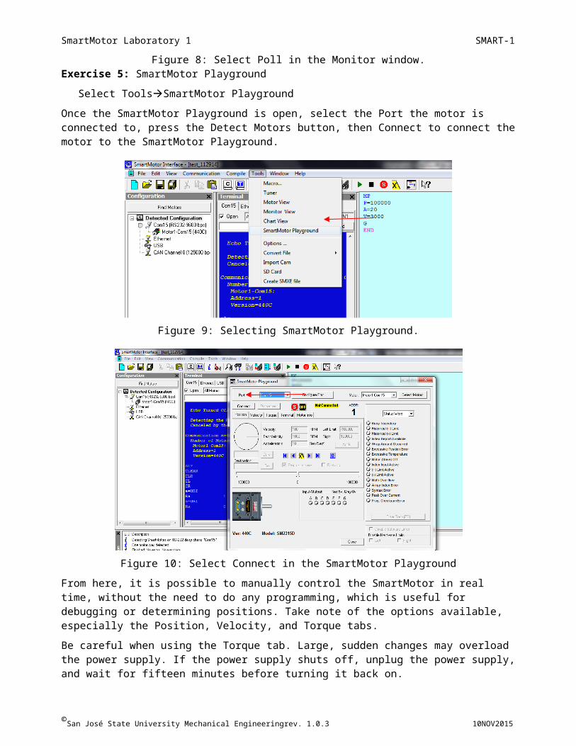
Exercise 5: SmartMotor Playground
Select ToolsSmartMotor Playground
Once the SmartMotor Playground is open, select the Port the motor is connected to, press the Detect Motors button, then Connect to connect the motor to the SmartMotor Playground.
Figure 9: Selecting SmartMotor Playground.
Figure 10: Select Connect in the SmartMotor Playground
From here, it is possible to manually control the SmartMotor in real time, without the need to do any programming, which is useful for debugging or determining positions. Take note of the options available, especially the Position, Velocity, and Torque tabs.
Be careful when using the Torque tab. Large, sudden changes may overload the power supply. If the power supply shuts off, unplug the power supply, and wait for fifteen minutes before turning it back on.
Exercise 6: Programming, MP (Mode Position)
Open a new document by selecting File New. A new window should appear on the right side. This editor window is where the code is downloaded to the motor.
Type in the simple code listed in Figure 11 to make the SmartMotor move to the specified position (100,000 encoder counts).
©San José State University Mechanical Engineering rev. 1.0.3 10NOV2015
SmartMotor Laboratory 1 SMART-1
Figure 11: Simple code to make the motor move to the position P using MP (Mode Position). A is acceleration, and the V is velocity. The G commands the motor to Go, and END ends the program when the motor reaches the destination.
Once the code is typed in the editor window, right-click in the Editor window, and select ‘Compile & Transmit SMX file’, or press F5. Select the motor used on the right side, double click the motor, then click Yes OKRun.
Figure 12: Right click over Editor Window, and click on Compile & Transmit SMX file, or press f5
Figure 13: Select motor used on the right hand side.
©San José State University Mechanical Engineering rev. 1.0.3 10NOV2015

SmartMotor Laboratory 1 SMART-1
Figure 14: Select Yes to all of the motors on this channel.
Figure 15: Select OK, then press RUN
What does the motor do once the program is downloaded?
Once this program executes, declare V=30,000. What does this RPM value refer to, the shaft or the encoder?
Exercise 7: Programming, MV (Mode Velocity)
Open a new document, and input in the following code. Follow the steps listed in Exercise 6 above to download the program to the SmartMotor.
Figure 16: Mode Velocity
©San José State University Mechanical Engineering rev. 1.0.3 10NOV2015

SmartMotor Laboratory 1 SMART-1
When downloaded to the SmartMotor, what does the SmartMotor do?
Exercise 8: Programming, MT (Mode Torque)
Open a new document, and input in the following code. (Do NOT use a torque value higher than 512 if you don’t want to risk disabling your power supply for 15 minutes)
Figure 17: Mode Torque
What happens when toggle switch 8 on the SmartBox BCD is flipped? Now put toggle switch 8 back to its original position, and flip GO on the SmartBox BCD interface unit. What happens when the GO toggle switch is flipped to ON?
Exercise 9: Going between positions using TWAIT
Create a new document, and input in the following code. Use Monitor View to determine if the SmartMotor spins in both directions.
Figure 18: Example of two positions using the TWAIT function between different commands. Use Monitor View to keep track of position.
©San José State University Mechanical Engineering rev. 1.0.3 10NOV2015

SmartMotor Laboratory 1 SMART-1
Exercise 10: Using IOs to move between positions
You determine the states of the IO port switches by using certain commands. Typing UAI, UBI, UCI, … will poll the state of the switches. In the terminal, typing a=UBI, then Ra will return the state of switch B. Using this in a script allows the motor to be controlled based on the switch state.
Type in the following code:
Figure 19: Example of how to use the SmartBox BCD controller with toggle switch B.
When the program is downloaded to the SmartMotor, what does the SmartMotor do when the program is executed? Play with the toggle switches, and report what happens. What happens when you remove the TWAIT lines?
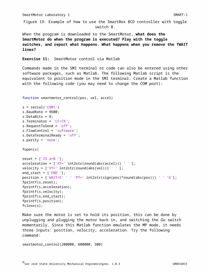
Exercise 11: SmartMotor control via Matlab
Commands made in the SMI terminal or code can also be entered using other software packages, such as Matlab. The following Matlab script is the equivalent to position mode in the SMI terminal. Create a Matlab function with the following code (you may need to change the COM port):
function smartmotor_control(pos, vel, accel) s = serial('COM1')s.BaudRate = 9600;s.DataBits = 8;s.Terminator = 'LF/CR';s.RequestToSend = 'off';s.FlowControl = 'software';s.DataTerminalReady = 'off';s.parity = 'none'; fopen(s)
©San José State University Mechanical Engineering rev. 1.0.3 10NOV2015

SmartMotor Laboratory 1 SMART-1
reset = ['ZS a=0 '];acceleration = ['AT=' int2str(round(abs(accel))) ' ' ];velocity = ['VT=' int2str(round(abs(vel))) ' ' ];end_start = ['END '];position = ['WAIT=5' ' ' 'PT=' int2str(sign(pos)*round(abs(pos))) ' ' 'G'];fprintf(s,reset);fprintf(s,acceleration);fprintf(s,velocity);fprintf(s,end_start);fprintf(s,position);fclose(s);
Make sure the motor is set to hold its position, this can be done by unplugging and plugging the motor back in, and switching the Go switch momentarily. Since this Matlab function emulates the MP mode, it needs three inputs: position, velocity, acceleration. Try the following command:
smartmotor_control(200000, 800000, 300)
What happens when the SmartMotor runs this command? Without turning off the motor, run the command again? What happens this time? Then execute the following without turning it off:
smartmotor_control(0, 800000, 300)
What happens this time? It is also possible to control the smartmotor with Python, in a similar fashion as in Matlab, allowing for integration with other programs.
References
Class 4 SmartMotor Training Overview: http://www.engr.sjsu.edu/bjfurman/courses/ME190/Lab_related/SmartMotor%20related/Class%204%20SmartMotorTrainingOverview.doc
Class 4 SmartMotor Interfacing: http://www.engr.sjsu.edu/bjfurman/courses/ME190/Lab_related/SmartMotor%20related/Class%204%20SmartMotor%20Interfacing.doc
Animatics Institute Training Manual: http://www.engr.sjsu.edu/bjfurman/courses/ME190/Lab_related/SmartMotor%20related/AnimaticsInstituteTrainingManual2008.pdf
©San José State University Mechanical Engineering rev. 1.0.3 10NOV2015
SmartMotor Laboratory 1 SMART-1
Appendix A
©San José State University Mechanical Engineering rev. 1.0.3 10NOV2015

SmartMotor Laboratory 1 SMART-1
Appendix B
©San José State University Mechanical Engineering rev. 1.0.3 10NOV2015