sand2014-xxxxr ldrd project number:180788 ldrd project...
TRANSCRIPT

SAND2014-XXXXRLDRD PROJECT NUMBER: 180788LDRD PROJECT TITLE: Electrochemical Solution Growth of Magnetic NitridesPROJECT TEAM MEMBERS: Todd C. Monson and Charles (CJ) J. Pearce
ABSTRACT:
Magnetic nitrides, if manufactured in bulk form, would provide designers of transformers and inductors with a new class of better performing and affordable soft magnetic materials. According to experimental results from thin films and/or theoretical calculations, magnetic nitrides would have magnetic moments well in excess of current state of the art soft magnets. Furthermore, magnetic nitrides would have higher resistivities than current transformer core materials and therefore not require the use of laminates of inactive material to limit eddy current losses. However, almost all of the magnetic nitrides have been elusive except in difficult to reproduce thin films or as inclusions in another material. Now, through its ability to reduce atmospheric nitrogen, the electrochemical solution growth (ESG) technique can bring highly sought after (and previously inaccessible) new magnetic nitrides into existence in bulk form. This method utilizes a molten salt as a solvent to solubilize metal cations and nitrogen ions produced electrochemically and form nitrogen compounds. Unlike other growth methods, the scalable ESG process can sustain high growth rates (~mm/hr) even under reasonable operating conditions (atmospheric pressure and 500 °C). Ultimately, this translates into a high throughput, low cost, manufacturing process. The ESG process has already been used successfully to grow high quality GaN. Below, the experimental results of an exploratory express LDRD project to access the viability of the ESG technique to grow magnetic nitrides will be presented.
INTRODUCTION:
Magnetic nitrides (FexNy), if manufactured in bulk form, would provide system designers with a new class of better performing and affordable soft magnetic materials. According to experimental results from thin films and/or theoretical calculations, magnetic nitrides would have magnetic moments well in excess of current state of the art soft magnets. Furthermore, magnetic nitrides would have higher resistivities than current transformer core materials and therefore not require the use of laminates of inactive material to limit eddy current losses. However, synthesis of magnetic nitrides has been elusive except in difficult to reproduce thin films or as inclusions in another material.
The electrochemical solution growth (ESG) technique, through its ability to reduce atmospheric nitrogen, can bring highly sought after (and previously inaccessible) new magnetic nitrides into existence in bulk form. This method utilizes a molten salt as a solvent to solubilize metal cations and nitrogen ions produced electrochemically and form nitrogen compounds. Unlike other growth methods, the scalable ESG process can sustain high growth rates (~mm/hr) even under reasonable operating conditions (atmospheric pressure and 500°C). Ultimately, this
SAND2014-18584R
translates into a high throughput, low cost, manufacturing process. The ESG process has already been used successfully to produce gallium nitride (GaN).
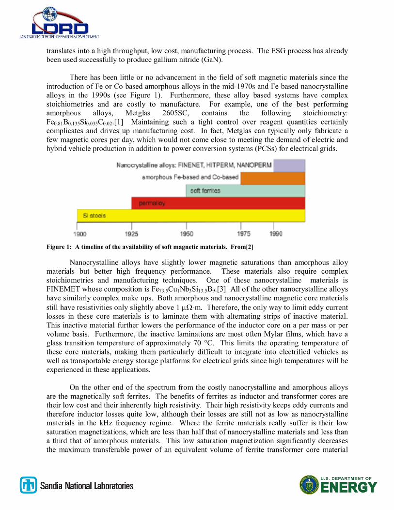
There has been little or no advancement in the field of soft magnetic materials since the introduction of Fe or Co based amorphous alloys in the mid-1970s and Fe based nanocrystalline alloys in the 1990s (see Figure 1). Furthermore, these alloy based systems have complex stoichiometries and are costly to manufacture. For example, one of the best performing amorphous alloys, Metglas 2605SC, contains the following stoichiometry: Fe0.81B0.135Si0.035C0.02.[1] Maintaining such a tight control over reagent quantities certainly complicates and drives up manufacturing cost. In fact, Metglas can typically only fabricate a few magnetic cores per day, which would not come close to meeting the demand of electric and hybrid vehicle production in addition to power conversion systems (PCSs) for electrical grids.
Figure 1: A timeline of the availability of soft magnetic materials. From[2]
Nanocrystalline alloys have slightly lower magnetic saturations than amorphous alloy materials but better high frequency performance. These materials also require complex stoichiometries and manufacturing techniques. One of these nanocrystalline materials is FINEMET whose composition is Fe73.5Cu1Nb3Si13.5B9.[3] All of the other nanocrystalline alloys have similarly complex make ups. Both amorphous and nanocrystalline magnetic core materials still have resistivities only slightly above 1 m. Therefore, the only way to limit eddy current losses in these core materials is to laminate them with alternating strips of inactive material. This inactive material further lowers the performance of the inductor core on a per mass or per volume basis. Furthermore, the inactive laminations are most often Mylar films, which have a glass transition temperature of approximately 70 °C. This limits the operating temperature of these core materials, making them particularly difficult to integrate into electrified vehicles as well as transportable energy storage platforms for electrical grids since high temperatures will be experienced in these applications.
On the other end of the spectrum from the costly nanocrystalline and amorphous alloys are the magnetically soft ferrites. The benefits of ferrites as inductor and transformer cores are their low cost and their inherently high resistivity. Their high resistivity keeps eddy currents and therefore inductor losses quite low, although their losses are still not as low as nanocrystalline materials in the kHz frequency regime. Where the ferrite materials really suffer is their low saturation magnetizations, which are less than half that of nanocrystalline materials and less than a third that of amorphous materials. This low saturation magnetization significantly decreases the maximum transferable power of an equivalent volume of ferrite transformer core material

versus materials with higher saturation magnetizations. Therefore, ferrites are very unattractive for high power density applications, such as in electrified vehicles and transportable energy storage and PCSs. Other materials, such as Si steels and permalloy, have performance characteristics such as high loss that do not make them viable choices for high power density and frequency applications either and will therefore not be discussed further here.
Magnetic nitrides, if manufactured in bulk form, could provide power systems designers with a new class of better performing inductor and transformer core materials. According to experimental results from thin films and/or theoretical calculations many of the magnetic nitrides would have magnetic moments well in excess of current state of the art soft magnetic materials. Furthermore, the experimental data and theoretical predictions that do exist suggest some of these materials would be magnetically soft and therefore ideally suited for use in inductor and transformer cores. One of the iron nitrides predicted to have a low coercivity is ’-Fe4N, which makes it the material of interest for our proposed research. Table 1 lists the saturation magnetization and resistivity of an amorphous alloy material (Metglas 2605SC), two nanocrystalline materials (FINEMET and VITROPERM), a high saturation magnetization ferrite, and ’-Fe4N. The values for -Fe are also provided as a reference. Due to nitrogen incorporation into its crystal structure, ’-Fe4N is predicted to have a resistivity two orders of magnitude higher than amorphous and nanocrystalline alloys and therefore will not require the use of inactive material laminates to mitigate eddy current losses. The synthesis of bulk ’-Fe4N would create a new magnetic core material with a saturation magnetization a factor of ~1.6X greater than nanocrystalline alloys and a resistance two orders of magnitude higher. And by manufacturing ’-Fe4N using the ESG process and consolidating it using a low temperature field assisted sintering technique (FAST), the cost of ’-Fe4N transformer and inductor cores will be on the order of ferrite cores and therefore significantly lower than amorphous and nanocrystalline alloys. The military, power systems developers, electric vehicle component manufacturers, and utility companies would all be potential users of ESG synthesized ’-Fe4N.
Magnetic Material Js (T) (m)
Metglas 2605SC 1.60 1.37
FINEMET (Hitachi) 1.25 1.20
VITROPERM (Vacuumschmelze) 1.20 1.15
Ferrite (Fexxocube) 0.52 5x10⁶
-Fe 2.15 0.05
’-Fe4N 1.89 ~200
Table 2: The saturation magnetizations (Js(T)) and resistivity () of amorphous and nanocrystalline magnetic materials, ferrites, ’-Fe4N, and -Fe (listed as a reference).[1,3-6]
The ESG technique developed by Sandia Labs has the ability to bring highly sought after new magnetic nitrides into existence in bulk form. One of the fundamental differences of the ESG technique which makes the growth of challenging materials possible is that it brings charged ionic species (rather than neutral atoms) together to form a new compound. ESG has already been used successfully by Sandia National Labs to grow GaN at low temperatures (500 C) and ambient pressure, and EERE’s Advanced Manufacturing Office is currently supporting a 3-year effort to grow bulk GaN by the ESG technique. In stark contrast, any other method used to grow bulk GaN requires extremely high pressures (> 4000 atmospheres) and temperatures.
DETAILED DESCRIPTION OF EXPERIMENT/METHOD:
There has been no success to date in producing magnetic transition metal nitrides in bulk form. ’-Fe4N has only been produced in thin film form and even that has been deemed as quasi-stable.[5]
Our proposal to synthesize ’-Fe4N under conditions conducive to large scale manufacturing is based on a recently patented ESG process at Sandia National Laboratories that promises to overcome these limitations by approaching the problem from a completely different angle. The method utilizes molten salt as a solvent to solubilize metal cations and nitrogen ions produced by electrochemical methods. These ions then react in solution to form nitrogen compounds. Unlike other growth methods, the ESG process has a very wide kinetic and thermodynamic window, and therefore the growth rate can be very high (~mm/hr) even under reasonable operating conditions (atmospheric pressure and 500 °C), making the process scalable. Ultimately this translates into a high throughput, low cost manufacturing process. The ESG process has already been successfully used to grow GaN crystals. An image of GaN crystallites and their corresponding X-ray diffraction (XRD) spectra is shown in Figure 2.

Figure 2: Crystallites of GaN under UV light and X-ray diffraction pattern confirming GaN structure grown by the ESG technique.
The ESG process should translate to forming transition metal nitrides. In fact, a research group in Japan demonstrated the growth of a ’-Fe4N film several m in thickness via electroplating an iron wire in molten salt using Li3N as a nitrogen source.[7] Figure 3 shows the cross section of an iron electrode imaged with a scanning electron microscope (SEM). A film of ’-Fe4N > 20 m thick formed via pulse electrolysis is clearly visible. An XRD spectrum from an iron electrode after potentiostatic anodic electrolysis is displayed in Figure 4. Diffraction from the ’-Fe4N with a secondary phase of -Fe is clearly visible.
Figure 3: Cross-sectional SEM image of iron electrode after potential pulse electrolysis.[8]

Figure 4: XRD pattern of iron electrode after potentiostatic anodic electrolysis.[8]
With the demonstration of both growth of a ’-Fe4N film via electroplating in molten salt and growth of GaN via the ESG process, it is reasonable to infer that it should also be possible to grow ’-Fe4N via the continuous reduction of nitrogen and the corresponding oxidation of the metallic iron.
Current processes to make nitrides utilize high temperatures and pressures to break the nitrogen bond. Instead, the dinitrogen triple bond can be broken at an electrode surface in a molten chloride salt according to the following reaction:
½N2 + 3e- N-3 [7]
Thus, dinitrogen can be activated electrochemically at a nickel electrode in molten salt at atmospheric pressure and temperatures between 400 and 550°C. The triply-charged nitride anion (N-3) is unstable in most environments, but is quite stable in t he molten chloride salt. Furthermore, it is quite soluble; literature suggests a solubility of several mole percent. Now that nitrogen reactivity problem has a path forward; in any electrochemical reaction, if a species is being reduced at one electrode, another species must be oxidized at the opposite electrode:
Fe(l) Fe+3 + 3e-
Unlike most electrochemical systems in which the oxidation reaction produces an ion in solution and the reduced species is a solid precipitate at an electrode surface (electroplating), in this case each reaction produces ions that are soluble in the molten salt electrolyte. The ions are available for reaction with each other in solution. If nothing else changes in the system, Fe xNy
will precipitate by an autonucleation mechanism. We have produced crystallites of GaN on the order of a millimeter or more in fewer than 2 hours under unoptimized conditions, which illustrates the favorable nature of the kinetics: if the kinetics were too fast, only nanoscopic dimensions would be attainable; too slow kinetics and the growth would be limited to micron-sized particles. Another available reaction pathway is that the negatively charged nitride ions react at the positively charged metal electrode, and vice versa.

The valences of the individual ions can be controlled electrochemically to obtain different stoichiometries/phases of materials. The phases of materials that autonucleate in solution can be tailored by controlling which charged species is produced. In the case of the work proposed here, mixed-valent ’-Fe4N can be produced by alternating the voltage on the iron anode between the Fe+, Fe+2, and Fe+3 states.
ESG is NOT electroplating. Ions are produced electrochemically at electrode surfaces in solution and allowed to react with each other in solution. No bias is applied to a substrate during growth. Relying on electrical bias to force growth would not be a practical approach as nitrides are insulating solids and would quickly produce rough deposits and be self-limiting, rather than producing bulk material. Purity is an issue with every bulk growth technique. The salts can be purified electrochemically—electrochemistry is sensitive to 1014cm-3 for electroactive species. Thus we believe that as the process development progresses, purification to sufficiently pure levels will be attainable. This is also leveraged by work performed for the GaN project. Parasitic reactions are also an issue with every growth process. The higher the concentration of ions in solution, the faster the growth rate—but so is the expected parasitic reaction rate of metal ions at the nitrogen electrode and oxidation of nitride to nitrogen gas at the metal electrode. This will have to be balanced through development activities, such as reactor design. Capital Equipment is very affordable—the big ticket items are a potentiostat and an atmosphere-controlled glovebox. Growth rate is expected to be on the order of mm/hr, according to multiple independent calculations.
ESG is a unique approach to materials synthesis. In its essence, ESG promises the ability to grow polycrystalline and homogeneous bulk materials of incongruently-melting multicomponent solids with one or more volatile components by growing them in solution from their precursor ions, which are generated electrochemically.
Unlike other growth methods, where the kinetics are driven by temperature and pressure, the electrochemical method completely eliminates the need for very high temperatures and pressures. The electrochemical reduction of dinitrogen gas offers a unique and compelling pathway to generate a sufficiently reactive nitride precursor in solution in high quantities, thus enabling facile solution growth at atmospheric pressure and modest temperatures. In the case of ESG, sufficiently high molar concentration (>1%) of reactive nitride (N-3) ions in solution can be produced at low temperature (500 oC) and atmospheric pressure conditions. Goto and Ito and Sandia have earlier demonstrated that a high rate of nitride ions production can be sustained for extended periods in LiCl-KCl salts; an example is shown in Figure 5. Thus, the major advantage of iron nitride growth through ESG is that the method is a low temperature, atmospheric pressure technique with potential for high growth rates. The process therefore affords a unique opportunity to produce novel magnetic nitrides.

Figure 5: Current density of N-3 in a LiCl-KCl electrolyte.[7]
Preliminary experiments to demonstrate the method were performed in a simple reactor
shown in Figure 6 (a) with a LiCl-KCl eutectic at 450°C, and with Ga metal and Li3N as the
precursors. A pool of molten gallium metal was anodically dissolved with nitride ions in
solution to yield multiple single crystals of GaN, the largest of these was about 1 mm in diameter
(see Figure 6(b)). Voltages were maintained within the electrochemical voltage window of the
salt (~3.5V), current densities ranged from A/cm2 to several A/cm2, and the electrolysis was
performed for about two hours at 450 °C. The formation of wurtzite GaN was verified by
powder XRD and energy dispersive x-ray spectroscopy (EDS). We propose to grow ’-Fe4N in
almost exactly the same fashion by replacing the molten gallium with an iron electrode.

Figure 6: ESG of GaN showing a schematic of the setup and GaN crystals grown from molten salt.
RESULTS:
The initial part of our effort focused on building our experimental setup. Due to the hygroscopic nature of the LiCl/KCl eutectic salt and potential reactivity of iron cations, all experiments were carried out in a nitrogen purged glove box (Innovative Technology, Inc.). In order to avoid any potential undesirable reactions from impurities in the molten LiCl/KCl solvent, trace metals basis (99.99% purity) eutectic LiCl/KCl was purchased and used from Sigma Aldrich. From previous efforts in the related bulk GaN growth program, we knew that most beaker/crucible materials are etched when in contact with molten halide salts for any length of time. This includes Pyrex, quartz, alumina, Inconel, and other materials generally considered to be quite robust and corrosion dependent. For this reason, silicon carbide (SiC) crucibles were chosen for this set of experiments. Direct sintered SiC crucibles ( Ultra-SiC SC30) were purchased from CoorsTek. These high quality 2” diameter and 2.5” high SiC crucibles were manufactured without any excess Si added as a binder. For all experiments, a Ag/AgCl reference electrode was constructed using trace metals basis ( 99.99 %) silver wire from Sigma Aldrich and 0.1 molal AgCl in eutectic LiCl/KCl inside a medium walled Pyrex NMR tube from Norell, Inc. (Pyrex conducts Ag+ ions at elevated temperatures). The small surface area of Pyrex exposed to the molten salt (and therefore small amount of impurities generated by Pyrex etching) could be tolerated for iron nitride growth experiments.
A total of four experiments were conducted using lithium nitride (Li3N) as a nitrogen source. These experiments were conducted to see if we could replicate the initial results of Goto

and Ito and ensure that we could create the proper conditions for iron nitride electrochemical synthesis.[7,8] We also wished to build and improve upon their results using Li3N as a nitrogen source, as for some applications, this may be the most expedient way to synthesize iron nitride films use in transformers. Prior to all growth experiments, cyclic voltammetry (CV) scans were collected to characterize the behavior of the working and counter electrodes in the molten salt solvent. As possible, CVs were collected periodically during growth runs to characterize and document evolution of the molten salt, electrodes, and growth conditions. Two experiments were conducted using an iron wire from Sigma Aldrich (trace metals basis, 99.99 %) as the working electrode (WE) and an aluminum wire, also from Sigma Aldrich (trace metals basis, 99.999 %) as the counter electrode (CE). In one experiment, growth of iron nitride was conducted in a potentiostatic mode, holding the WE potential at -1.6 V vs. Ag/AgCl for a total of three hrs. In a second growth experiment, iron nitride growth was conducted using a pulsed method, alternating the WE potential between -1.9 V vs. Ag/AgCl (holding for 10 s) and -0.9 V vs. Ag/AgCl (holding for 1 s). The total growth period for the pulsed experiment was one hour. By pulsing the Fe WE, some of the iron would be oxidized, making it reactive with solvated N-3
anions. During both experiments, a significant portion of the Al CE immersed in the salt was consumed, indicating that aluminum was being oxidized during the growth runs. This was an interesting but somewhat troublesome result that was not mentioned in the papers by Goto and Ito.[7,8] A third experiment using lithium nitride as a nitrogen source was conducted, but this time the iron wire was replaced with an iron foil also purchased from Sigma Aldrich (tracemetals basis, 99.99 %). The motivation for switching to an iron foil was to make XRD characterization more straightforward (discussed in more detail below) and since foils of FexNy
could be directly laminated and shaped directly into inductor and transformer cores. This iron nitride growth experiment was also conducted in a pulsed mode, alternating the WE potentialbetween -1.9 V vs. Ag/AgCl (holding for 10 s) and -0.9 V vs. Ag/AgCl (holding for 1 s). Once again, during the growth cycle, the Al CE immersed in the molten salt was largely consumed.
In the final experiment utilizing Li3N as a nitrogen source, the Al CE was replaced with a glassy carbon rod (>99% activated carbon, <1% Quartz) 5 mm in diameter and purchased from Alfa Aesar. We wished to see if the glassy carbon would be more resistant to oxidation and not be consumed during the electrochemical growth cycle. Once more, a potentiostatic growth was conducted, holding the potential of the Fe WE at -1.7 V vs. Ag/AgCl and holding for 1 hr. However, the glassy carbon CE did not prove more resistant to oxidation and was entirelyconsumed during the electrochemical growth period.
One final experiment was run, replacing Li3N with flowing nitrogen gas as the nitrogen source. Our intention here was to advance beyond current state of the art and not rely on Li3N as a nitrogen source. Under this configuration, our WE became a porous nickel mesh and flowing nitrogen gas. The nickel surface allows for electron transfer to the N2 and acts as a catalyst for its reduction. This electrode was constructed using a custom Pyrex gas dispersion tube with a coarse frit purchased from Chemglass Life Sciences. A nickel mesh was then fit tightly over the coarse frit and secured with nickel wire. Finally, nickel wire was then run along the length of the dispersion tube and provided a place to make electrical contact to the electrode. The top of the dispersion tube was fit with a Swagelok fitting and Teflon ferrule to allow connection to ¼” tubing and a source of nitrogen gas external to the glovebox. A flow meter external to the glovebox allowed for control over the flow rate of the N2 gas. In this configuration with the

Ni/N2 WE, the iron wire became the CE. Growth was once again be conducted in potentiostatic mode, holding the voltage of the WE such that iron would steadily be oxidized and solubilized in the molten salt, providing a steady stream of electrons for the reduction of N2 to N-3 anions. Another benefit to this growth configuration would be the elimination of the oxidation of the CE as in the Li3N based experiments. A photograph of the experimental setup for ESG using flowing N2 gas is shown in Figure 7.
Figure 7: Photograph of experimental setup for ESG of iron nitrides using flowing N2 gas.
Prior to the growth run in the flowing N2 configuration, CVs were once again collected of the system. After starting the flow of N2 gas, an additional CV was collected and then CVs collected at 5 min. increments during the growth cycle to observe evolution of the electrodes, salt, and overall growth conditions. N2 reduction occurs at a very negative potential close to Li+ reduction. Therefore, the growth cycles were conducted using a potentiostatic hold at -2.55 V vs. Ag/AgCl. These growth conditions were maintained for a total of one hour, at which time the Fe wire CE was entirely consumed. This gave us a good measure of confidence that the growth proceeded properly with the simultaneous reduction of N2 and oxidation of Fe.
One challenge with this growth method is that both Fe+3 and N-3 would both be solubilized in the LiCl/KCl and react in solution, forming FexNy crystallites that would precipitate out of solution. It is then necessary to recover the iron nitride powders from the molten salt. In order to recover the iron nitride product, a hot filtering of the LiCl/KCl solvent was completed. A filter was constructed using a coarse nickel mesh and the molten salt poured through the filter at the conclusion of the experiment. This setup worked well and black powders were collected during filtration, leaving clean salt to pass through the filter and cool in a crystallization dish.

DISCUSSION:
After each experiment the product was collected and analyzed using XRD. In the Li3N experiments, the product was the iron wire or foil WE as nitride ions should have reacted with the iron electrode during the growth phase. When our experiments were run in the flowing N2
configuration, our product was the powder captured in the Ni mesh filter. In all cases, as much of the LiCl/KCl salt as possible was washed off using dried and distilled dimethyl sulfoxide (DMSO). This way, any FexNy could be cleaned without exposing it to potentially corrosive salt water.
Next, the product was analyzed using XRD. The first XRD attempts were made using a Bruker D2 Phaser user instrument. An extremely conservative handling of the samples was used, mounting them inside the glovebox in a sealed polymer dome designed by Bruker to be used with the D2 Phaser. Unfortunately, a combination of background from the polymer dome, high fluorescence from the iron in the sample, and the non-ideal geometry of the iron wire did not allow for good analysis of our samples on the D2 Phaser. In fact, no iron (or other) diffraction peaks could be detected using this instrument.
Due to the difficulties in collecting XRD on the D2 Phaser with the sample sealed inside a plastic dome, our XRD measurements were instead made with one of Mark Rodriguez’s XRD instruments inside a Be dome with a zero background holder. This XRD instrument had improved electron flux in addition to a Si monochromator, which blocks almost all iron fluorescence. This improved the signal to noise of our XRD measurements and allowed us to resolve iron diffraction peaks in our data.
The XRD from one of the non-pulsed Li3N based experiments is shown in Figure 8. This spectrum shows diffraction from Fe and KCl. It is interesting that the DMSO wash appeared to remove all LCl but left some KCl behind on the surface of the electrode. This sample, as all the iron wire electrode samples, had a dark grey surface layer as a result of the electrochemical growth cycle. However, this layer was not sufficiently ordered to yield any sharp diffraction peaks in the XRD spectra. It is clear from the appearance of Fe diffraction peaks that the X-rays were indeed penetrating this surface layer. This means that in this sample, any iron nitride that might be present in the surface layer was either not diffracting at all or producing only a very broad background that is visible at angles of 2 < 40.

Figure 8: XRD spectrum of iron wire working electrode from potentiostatic growth experiment using Li3N as a nitride source.
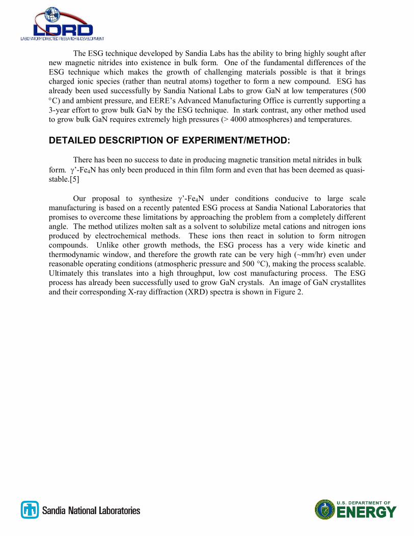
An XRD spectra from a pulsed Li3N experiment where Al was used as the counter electrode is displayed in Figure 9. Once again, this spectra shows diffrac tion from Fe and KCl (but no LiCl). This sample also had a dark grey surface layer but once again either no diffraction or only a very broad amorphous background from this layer could be seen in the XRD spectra. One other phase that was detected in this spectra was LiAl. This is most likely the result of the aluminum counter electrode oxidizing, reacting with Li+ ions and electrons generated through the oxidation of N-3, and then depositing on the Fe WE. The formation of LiAl was never discussed in the two journal articles written by Goto and Ito, although it seems that they would have encountered the formation of LiAl since our electrochemical conditions were identical. [7,8] The other iron wire and foil samples from the remaining Li3N based experiments only had iron and KCl peaks when their XRD spectra was analyzed.
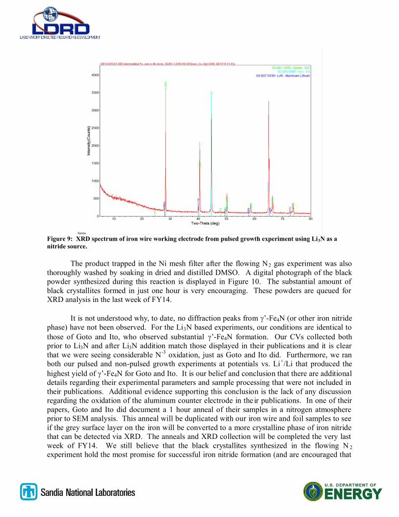
Figure 9: XRD spectrum of iron wire working electrode from pulsed growth experiment using Li3N as a nitride source.
The product trapped in the Ni mesh filter after the flowing N2 gas experiment was also thoroughly washed by soaking in dried and distilled DMSO. A digital photograph of the black powder synthesized during this reaction is displayed in Figure 10. The substantial amount of black crystallites formed in just one hour is very encouraging. These powders are queued for XRD analysis in the last week of FY14.
It is not understood why, to date, no diffraction peaks from ’-Fe4N (or other iron nitride phase) have not been observed. For the Li3N based experiments, our conditions are identical to those of Goto and Ito, who observed substantial ’-Fe4N formation. Our CVs collected both prior to Li3N and after Li3N addition match those displayed in their publications and it is clear that we were seeing considerable N -3 oxidation, just as Goto and Ito did. Furthermore, we ran both our pulsed and non-pulsed growth experiments at potentials vs. Li+/Li that produced the highest yield of ’-Fe4N for Goto and Ito. It is our belief and conclusion that there are additional details regarding their experimental parameters and sample processing that were not included in their publications. Additional evidence supporting this conclusion is the lack of any discussion regarding the oxidation of the aluminum counter electrode in the ir publications. In one of their papers, Goto and Ito did document a 1 hour anneal of their samples in a nitrogen atmosphere prior to SEM analysis. This anneal will be duplicated with our iron wire and foil samples to see if the grey surface layer on the iron will be converted to a more crystalline phase of iron nitride that can be detected via XRD. The anneals and XRD collection will be completed the very last week of FY14. We still believe that the black crystallites synthesized in the flowing N 2
experiment hold the most promise for successful iron nitride formation (and are encouraged that
this ESG route eliminates many troublesome issues, such as consumption of the counter electrode).
Figure 10: Photograph of black crystallites synthesized during flowing N2 gas ESG experiment and captured in a nickel mesh filter.
ANTICIPATED IMPACT:
The synthesis of iron nitrides using ESG will create a new opportunity to fabricate affordable and commercially viable high saturation magnetization and low loss inductor/transformer core materials while also addressing current magnetic core shortfalls. These new materials will enable technological advancements such as better hybrid and electric vehicles, the integration of more renewable energy generation, and higher capability forward deployed military installations. Furthermore, the ability to synthesize and study a new class of magnetic materials in bulk form would have enormous implications in the basic research and understanding of magnetic materials.
Bulk iron nitrides would enable improved PCSs which are required as our nation transitions to a cleaner energy economy. Improved soft magnetic materials will be essential in enabling modern and efficient PCSs for the electrical grid, forward deployed military installations, and transportation. In the case of transportation, both electric and hybrid vehicles require power electronic inverters and converters for their operation. These components can add significant cost to the manufacture of electric vehicles and often require a large footprint which complicates inverter or converter design. One subcomponent which requires a substantial improvement in performance and decrease in cost is the passive inductor. In the case of electrical grids (which includes grids for forward deployed military installations), there is a

strong push towards integrating the output transformer within the PCS and operating at much higher frequencies (> 10 kHz). This approach, which leverages the high switching speed and high temperature performance of wide bandgap semiconductors, provides for a higher density PCS and increased performance. Smaller and lighter transformers that do not require thermal management would enable transportable energy storage and PCSs, which are becoming more attractive because of their short installation time and cost. Both vehicle and grid power systems require substantial improvements in inductor/transformer cores to minimize electrical losses at high frequencies and temperatures, while also increasing power handling capability. However, the development of new soft magnetic materials for these types of applications has only been an afterthought. We will seek out opportunities to further the progress made during this exploratory express LDRD and make the ESG of bulk iron nitrides a mature process that can contribute to the applications outlined above as well as other related applications.
The widespread availability of a new class of magnetic materials with high electronic resistivity would reduce the electrical losses (up to 40%) and footprint associated with passive magnetic components in hybrid and electric vehicles without driving up their cost. Additionally, these magnets (or variations on the stoichiometry/phases) could find use as replacements for expensive rare earth-based magnets in other energy efficiency applications. This would provide an opportunity to develop new low energy consumptive manufacturing enterprises in the United States. The electric vehicle and wind energy sectors in particular stand to benefit.
A long term goal (which is still several years away if additional funding can be secured) would be a transition of the ESG of iron nitrides to pilot scale manufacturing, the model for which can be heavily leveraged from ongoing work on gallium nitride for the semiconductor industry. Although the application space is very different, there are some core commonalities between the manufacturing processes (the magnetic nitrides being the far simpler one) from which each technology can benefit from the development of the other. Many of the materials compatibility issues relevant to sustained growth times can be transferred directly to the magnetic nitride process.
Additional sources of follow on funding will be sought out in order to further the research progress made in this exploratory express LDRD project. One of the first targets for additional funding would be a 2 or 3 year full LDRD project. An LDRD on the further development of a process to synthesize bulk magnetic nitrides could easily fit within the Materials investment area (IA). Given the many applications in the field of power electronics and energy, it is conceivable that the Energy and Climate IA could fund a project to mature the ESG of magnetic materialsand to fabricate and test devices out of the raw materials. Given the need for compact inductors and transformers in both NW and defense applications, the results from this exploratory express LDRD and potential for future maturation will be socialized with both the NW and Defense Systems & Assessments (DSA) IAs. The synthesis of new bulk magnetic materials is not trivial in terms of its implications to fundamental research either. Therefore, as our results are compiled and developed into a publication, DOE Office of Science may be engaged for additional funding.
CONCLUSION:

Sandia National Laboratories is a multi-program laboratory managed and operated by Sandia Corporation, a wholly owned subsidiary of Lockheed Martin Corporation, for the U.S. Department of Energy’s National Nuclear
Security Administration under Contract DE-AC04-94AL85000.
In conclusion, the laboratory infrastructure and experimental setups for the electrochemical solution growth (ESG) of iron nitrides has been developed and evaluated under this exploratory express LDRD. Multiple growth experiments were conducted using both Li3N and flowing N2
gas as a source of N-3 ions. The reduction of nitrogen gas was demonstrated and a substantial amount of black crystallites were collected from the N2 gas experiment. These powders will be examined using XRD in the last week of FY14.
REFERENCES
1. J. M. D. Coey, Magnetism and Magnetic Materials, Cambridge University Press, New York, 2010.2. L. A. Dobrzański, M. Drak and B. Ziębowicz, Journal of Achievements in Materials and
Manufacturing Engineering, 17 2006.3. B. J. Lyons, J. G. Hayes and M. G. Egan, Magnetic material comparisons for high-current
inductors in low-medium frequency DC-DC converters, 2007.4. M. S. Rylko, K. J. Hartnett, J. G. Hayes, M. G. Egan and Ieee, Magnetic Material Selection for High
Power High Frequency Inductors in DC-DC Converters, 2009.5. S. K. Chen, S. Jin, G. W. Kammlott, T. H. Tiefel, D. W. Johnson and E. M. Gyorgy, J. Magn. Magn.
Mater., 110 1992.6. H. Naganuma, R. Nakatani, Y. Endo, Y. Kawamura and M. Yamamoto, Science and Technology of
Advanced Materials, 5 2004.7. T. Goto and Y. Ito, Electrochim. Acta, 43 1998.8. T. Goto, R. Obata and Y. Ito, Electrochim. Acta, 45 2000.