sapr 81985j - apps.dtic.mil · sapr 81985j naval surface weapons center dahigren, virginia 22448...
TRANSCRIPT
NSWC TR 84-326
PRODUCTION OF SHAPED PARTSI OF NITINOLALLOYS BY SOLID-STATE SINTERING
00BY DAVID M. GOLDSTEIN
Ln RESEARCH AND TECHNOLOGY DEPARTMENT
15 OCTOBER 1984
Approved for public release; distribution is unlimited. D ETC
SAPR 81985j
NAVAL SURFACE WEAPONS CENTERDahigren, Virginia 22448 *Silver Spring, Maryland 20910

UNCLASSIFIEDSECUPITY CLASSIFICATION OF THIS PAGE (Whe~n Does Entered)__________________
REPOT DCUMNTATON AGEREAD INSTRUCTIONSREPOT DCUMNTATON AGEBEFORE COMPLETING FORM1. REPORT NUMBER 2,OTA SINNo3.VT S CATLGNME
NSWC TR 84-326 TASI . ATLGNUUBR
4. TITLE (and Subtitle) S. TYPE OF REPORT & PERIOD COVERED
PRODUCTION OF SHAPED PARTS OF NITINOL ALLOYS BYSOLID-STATE SINTERING 6.PERFORMING ORG. REPORT NUMBER
7. AUTHOR(#) a. CONTRACT OR GRANT NUMBER(@) --
David M. Goldstein 0
9. PERFORMING ORGANIZATION NAME AND ADDRESS 10. PROGRAM ELEMENT, PROJECT, TASKAREA & WORK UNIT NUMBERS
Naval Surface Weapons Center (Code R32) 627667, F66512,I~F66512001,White Oak R02AEOOI~Silver Spring, MD 20910 ______________
If. CONTROLLING OFFICE NAME AND ADDRESS 12. REPORT DATE
15 October 198413. NUMBER OF PAGES
3414. MONITORING AGENCY NAME & ADDRESS(I different from, Controlling Office) IS. SECURITY CLASS. (of this report)
UNCLASSIFIED
I~.DECL ASSI FICATION/ DOWN GRADINGSCHEDULE
16. DISTRIBUTION STATEMENT (of this Report)
Approved for public release; distribution unlimited.-
17. DISTRIBUTION STATEMENT (of the abstract entered Itn Block 20. If different from Report)
IS. SUPPLEMENTARY NOTES
19. KEY WORDS (Continue on reverse oid* It necessary and Identify by block number)
-,NITINOL. Pow~rMeauryShape Memory Alloys CA0 _rocess
,. Consolidation Pipe Fittings.
20. ABSTRACT (Continue on reverse sfide If neceecaty and fdentify by block number)
A solid state sintering process has been successfully adapted to
consolidating NITINOL alloy powders. NITINOL alloys are noted for their shapememory properties. The sintering process is performed at atmospheric pressureupon powders contained in an evacuated glass container.
Processing parameters are reported. Tubes and tubular tees were madeas well as solid round bars. Round bar stock was extruded and swaged.
Excellent shape memory properties were obtained.
DD I JAN 7 3 1473 EDITION OF I NOV 65 IS OBSOLETE UCASTT.
SECURITY CLASSIFICATION OF THIS PACE (When Data Entered) 9

NSWC TR 84-326
FOREWORD
This report presents the results of an Independent Exploratory Development(IED) Program conducted by the Naval Surface Weapons Center. Some portions ofthe Program were performed by the Specialty Steel Division of the Cyclops
Corporation. This study demonstrated that a low-cost, solid-state processdeveloped for tool steel manufacture could be successfully adapted to themanufacture of NITINOL (TiNi) alloys. This publication presents the state ofthe art of producing bulk metal and near net shape products from pre-alloyedNITINOL powders. The assistance of Mr. Robert Gasior and Cyclops Corporation isgratefully acknowledged.
Company and trade names are used in this report for technical informationonly.
Approved by:
JXCK R. DIXON, HeadMaterials Division P. J
". ° *. . -.
'.,,vc -!on For
DTICSELECTE
APR 8
U_
*. .. *::'ZY~. :.j,-J j .. . !i:......ii
.......~~~~~~~~~~~~~~~~~~~~~..............,-%...%-............... .,.. ........... e .. ,-..........,............,...... ..- , ... .

NSWC TR 84-326
CONTENTS
Chapter Page
I INTRODUCTION.................................COUPLINGS, BACKGRUND............. ........... 1SOLID-STATE SINTERING.......................2SHAPED PARTS...........................4
2 THE CAP PROCESS FOR NITINOL......................5BACKGROUND............................5EXPERIMENTAL CONDITIONS AND PROCEDURES..............6
POWDER PACKING...........................6EVALUATION PROCEDURES......................6CAP PROCESSING...........................6POWDER SIZING..... ........................ 7MECHANICAL PROCESSING......................11
3 SHAPED PARTS PRODUCTION........................15
4 CONCLUSIONS................................23
5 RECOMMENDATIONS............................25
REFERENCES................................27
iii /iv
2, 2._s _
NSWC TR 84-326
I LLUSTRATTIONS
Figure Page
1 PREVIOUSLY REPORTED DATA ON THE EFFECT OF COMPOSITION ON THERECOVERY TEMPERATURE OF NiTi ALLOYS.................3
2 NITINOL BULK METAL PRODUCED FROM POWDER BY THE CAP PROCESS . . . .12
3 CAP PROCESSED NITINOL AND EXTRUDED ROD ............... 13
4 CAP PROCESSED NITINOL TUBULAR PREFORMS...............16
5 MOLDS FOR SHAPED-FITTINGS AND CAP PROCESSING NITINOL TEE ....... 18-
6 MOLD DESIGNS FOR HOLLOW SHAPES .. .. .. .. .. .. .. .... 19
7 GRAPHITE-CORE TEE MOLD AND AS CAP'D NITINOL TEE ........... 21
TABLES
Table Page
1 DENSITIES OF NITINOL POWDER COMPACTS AFTER CAP PROCESSING ....... 8
2 EFFECT OF POWDER SIZE ON DENSIFICATION OF NITINOL POWDERS ....... 9
3 EFFECT OF SINTERING CYCLE AND POWDER SIZE ON DENSIFICATIONOF NITINOL.............................10
v/vi

NSWC TR 84-326
CHAPTER I
INTRODUCTION
NITINOL is an alloy of nickel and titanium which exhibits a shape memory
effect. The term Mshape memory effect6 (SME) is used to describe the ability of
certain alloys which, if deformed at a low temperature, will recover their prior
shape when heated.
The first shape memory alloy with engineering properties was invented by
Buehler and Wiley. Their patent for the alloy was filed in 1961 and granted in
1965. Upon the discovery of its unique properties, Buehler and Wiley designatedthe alloy as 55 NITINOL, to connote its composition and place of origin, i.e.,
55 weight percent Nickel, remainder Titanium. NOL was derived from the Naval
Ordnance Laboratory, which is now the Naval Surface Weapons Center.
COUPLINGS, BACKGROUND
A major early application based on NITINOL was the Cryofit® couplingdesigned by the Raychem Corporation, Menlo Park, California, in 1969. This
excellent coupling provided a pressure tight end-to-end connection between twotubes. Currently in wide use, it operates by contracting from its expanded
diameter upon being warmed to room temperature. The term "heat recoverablecoupling" (HRC) came into use at shipyards, with the use of the couplings forheavy wall piping for working pressures of 6000 psi. Expanded HRCs are stored
in liquid nitrogen until they are used. Heating the installed coupling is
accomplished by ambient air. The extensive developmental and test workinitiated by the Naval Sea Systems Command and the Raychem Corporation in 1973
ultimately led to the use of the Cryofit HRCs in shipboard piping systems.Lockheed, also in 1973, tested a 4-inch diameter coupling for the Navy. 1 In1975, the Electric Boat Division of General Dynamics recommended that a programbe conducted to qualify the couplings for possible use with submarines.
2
" " Raychem presented a paper in 1975 to the Sixth Submarine HydraulicsConference3 reporting on the use of the Cryofit System by Vickers Shipbuilding
Limited in British nuclear submarines. Ingalls Shipbuilding Division reported
on the successful introduction of HRCs into new naval construction in 1979. 4
Based on a 1981 study at Pearl Harbor Naval Shipyard, LCDR Baskerville, USN,
projected the potential usage of HRCs at the eight naval shipyards at 35,000couplings per year.5 On the supply side, Raychem currently offers a standard
size range of Cryofit HRCs for pipe sizes from 1/8 inch to 1-1/2 inch. Caskeyand Embry4 recognized the advantages that would accrue if shapes were to
become available, in addition to couplings. A report within the Naval SeaSystems Command6 subsequently reviewed the advantages of the development of
shaped fittings, such as tees, ells, etc.
°2.. . -

%NSWC TR 84-326
SOLID-STATE SINTERING
Historically, NITINOL alloys have been produced almost exclusively bymelting processes. These included arc, electron beam, and induction methods,frequently with second and even third re-melts. These techniques are required
by the nature of the alloy constituents, by the very narrow range of chemistryallowed, and by the criticality of compositional homogeneity. The correlationof charge, or analysis, chemistry with transition temperatures (SME recoverytemperatures) for NITINOL alloys has, in general, been inexact. The scatter ofthe data is visible in Figure 1. It is, however, to be recognized that heattreatments and the different methods used to measure transition temperatures
introduced their own contribution to the scatter.
In addition to the compositional (and, therefore, transition temperature) .variation from the melting process, there is an additional limitation in thecasting of NITINOL. This is due to the tendency of NITINOL, like other hightitanium content alloys, to react with the mold materials. Shape production,therefore, tends to be limited to very high value parts, due to mold costs.
Preparation of bulk metal by the solid-state sintering of pre-alloyedpowders is a means of avoiding these limitations.7 ,8,9 The Naval SurfaceWeapons Center and others have engaged in sporadic efforts to consolidateelemental nickel and titanium powders by cold isostatic pressing and subsequent
* sintering. Shape response of these materials was pronounced, but inferior tothat of a cast and wrought product. Pre-alloyed powders processed in the sameway tended to crack upon sintering of the cold pressed compact.
These difficulties suggested that hot isostatic pressing of pre-alloyedpowders would be a more assured route of achieving bulk metal with the desiredcharacteristics. Special Metals Corporation (SMC), New Hartford, New York, andAnn Arbor, Michigan was invited to produce several experimental powder lots totest this thesis. This resulted in the production of sintered and wroughtNITINOL wire with performance matching that of the cast and wroughtproduct.1 0 Their successful atomization of 50-pound melts and subsequentconsolidation of the powders was a significant technical accomplishment. SMC isnow a producer of NITINOL alloys. Although the hot isostatic pressing technique " .which was used produced a high-quality product, it remains as a relatively highcost method of consolidating powders to near net shape. It should be kept inmind, however, that the method itself produces high-quality bulk material, andis used for example, for highly stressed parts such as superalloy turbine wheeldiscs. This will be of interest and will be discussed subsequently, when theobjective of the hot isostatic pressing operation is increased densification,rather than the initial sintering.
In 1981 the Specialty Steel Division (since renamed "Cytemp") of CyclopsCorporation publicized a procedure which could substitute for hot isostaticpresing. Their process, identified as a Consolidation by Atmospheric Pressure(CAPW), entailed the use of glass molds and standard air-atmospherefurnaces. With such simple equipment the process can, and does, compete in themarketplace of modestly priced tool steels. These economics also iookedattractive when applied to the substantially higher priced NITINOL alloys. Itremained to be established, however, that the CAP process was applicable toNITINOL alloys.
22
-. .' . . . . .. .***.*.*. **. .. *. *. * .. ,.. ..... *a..,..* *. - . . * - *. *. *-

NSWC TR 84-326
175
150- 0 WANG, ET AL. 0
A WASILEWSKI, ET AL.U HANLON, ET AL.
12 0 DRENNEN, ET AL.V ECKELMEYER 00
v V V
00
75-
>0A50-
25-
0
48 49 50 51 52 53
ATOMIC % Ti
FIGURE 1. PREVIOUSLY REPORTED DATA ON THE EFFECT OF COMPOSITION ON THERECOVERY TEMPERATURE OF NiTi ALLOYS (REFERENCE 7)
3

NSWC TR 84-326
SHAPED PARTS
Directly and through its contractors %.he U.S. Navy is a major user ofcommercially manufactured HRCs. The Grumman-manufactured F-14 (TOMCAT) navalaircraft contains a substantial quantity of HRCs in its hydraulic systems. Thenewly constructed CG 76 (TICONDEROGA) and DDG 51 (BURKE) ships use HRCs. As aresult of overhaul and repair (0 & R) activities, every major class of naval -
surface ships now has HRCs aboard. The significance of pipe joining in these 0& R activities (and impact of major retrofit pro rams, e.g., USS IOWA), werereviewed in a Navy study on ship overhaul costs.fl
Cryofit HRCs, despite their relatively high cost, achieve their savingsthrough their reduction of installation labor, inspection costs, and reworkof damaged adjacent areas that occur in welding in restricted spaces-
1 1
Additionally, unlike welding, they may be used in repair of systems containingflammable fluids without purging the system.
HRCs were identified as a new technology for shipbuildingl2 in 1981, andas such fitted precisely into the guidelines of the Navy's ManufacturingTechnology and Shipbuilding Technology (MT/ST) Program Plan.
13
Clearly, HCRs have established their value to the piping crafts.
Given the Navy's long involvement with shape memory alloys and the HRCsbased on them, the development of shaped fittings for piping systems is anevolutionary step in increasing NITINOL utility to the Navy. This reportdescribes progress in this direction. JR
*From Reference 11, "The second largest potential for payoff in piping systemsrepair is in the labor costs for installing pipe sections in ships. Thelargest payoff itself is in reducing the time that submarines and carriersspend in overhaul while having valves overhauled. Piping and valve repairtogether constitute a major cost in overhaul."
4 .

NSWC TR 84-326
CHAPTER 2
THE CAP PROCESS FOR NITINOL
BACKGROUND
The CAP process 14 is one variant of many different powder metallurgyconsolidation procedures. The common starting material for these procedures is
usually a powder, often pre-alloyed. The advantages of powder sinteringtechniques include fabrication to near net shape, resulting in lowered finished
part cost; improvement of selected mechanical properties; and fabrication ofalloys not readily amenable to hot working. The CAP process is performed onpowders which have been contained in a glass mold. The glass itself is the sameborosijicate compos j ion widely found in laboratory ware bearing the namesKimax* and Pyrex(N . The CAP procedure is to fill a glass mold of theselected part shape with powders of the desired alloy composition, evacuate, andseal the mold under a high vacuum. The sealed glass envelope is then submergedin a crucible containing a refractory powder bed which will flow freely at the
planned sintering temperature. The crucible is placed in any air atmospherefurnace of suitable design and heated to the selected temperature. During the
course of heating, the glass softens and flows inward under the pressure exertedby the atmosphere. The free-flowing refractory bed, which surrounds the glass,
provides support for it as it softens. This enables dimensional change to occurwithout significant shape change.
A commercial sintering cycle is typically 12 to 24 hours for glassenveloped large parts, followed by partial cooling in the furnace and then
removal from the furnace. During cooling to below red-heat temperatures theglass envelope self strips from the metal. This is due to the differential oftheir contraction rates. The resultant metal part may be as high as 99 percentdense.
As practiced by Cyclops, CAP preforms as large as 2000 pounds have beenproduced. Alloy tool steels and a variety of super alloys, mostly with nickel
bases, have also been consolidated by the CAP process.
Determination of whether the CAP process was applicable to NITINOL alloys
began at the Naval Surface Weapons Center by using powders produced earlier bySpecial Metals Corp. These powders were produced from NITINOL ingots made in aconsumable electrode arc furnace. This latter method of melting produces aningot which may not be homogeneous either from side to side or bottom to top.
5
......... . .".. .*. .. *..*.*

NSWC TR 84-326
The SMC arc-melted ingots were re-melted in a vacuum induction furnaceusing a graphite crucible and atomized. While it is possible to directlyinduction melt and atomize the alloy by starting with elemental metals, it is pless reliable than starting with the pre-alloy; this is due to the reactivity ofelemental liquid titanium with graphite, which is negligible when it is buffered
with nickel.
Induction melting inherently produces a homogeneous liquid melt, adesirable feature for the s bsequent atomization. As the liquid metal is pouredin a thin stream from a s, ;cially designed pouring cup, it is impacted by one ormore jets of high pressure inert gas. The gas jets cause the liquid stream todiverge into liquid droplets, which rapidly solidify into sliver-like andglobular shapes. These atomized particles range in size from as long as 5 or6 m (1/4 inch) to as small as spheroids less than 44 ;Am (-0.002 inch). Thepowders are cooled in the inert atmosphere, emerging as bright to grey in color p(depending on size), and are essentially oxide free. They are not subject toinstantaneous combustion and do not appear to burn readily, allowing readyhandling of the powders in air. The powders from the various melts (identifiedas "Heats") were the starting materials for the following technical effort.
pEXPERIMENTAL CONDITIONS AND PROCEDURES
The following experiments delineated the conditions under which CAPprocessing would or would not be successful for NITINOL.
Powdar Packing
Powder packing is a function of powder size, shape, and mesh fractionsused. For -60 mesh Heat R79359 the packing factor was 50 percent; for -100 meshHeat 81510 it was -56 percent. These values are based on the density of solidNITINOL being 6.45 g/cc (0.234 lb/in 3 ); thus these are percentages of -theoretical density (TD).
Evaluation Procedures
Powders (-60 grams) were poured into test-tube shaped containers withenlarged lower sections. These were outgassed for 1/2 hour to a pressure of0.7 am.
CAP Processing
An evacuated and sealed glass envelope with -60 grams of -100 mesh Heat81510 was submerged in a plumbago (clay graphite) crucible containing Dixon 1101
flake graphite at 25*C. The crucible was heated and held at 9500C to 975*C for12 hours. It was furnace cooled overnight to 600*C. The specimen was removedfrom the crucible, causing about 95 percent of the glass envelope to undergoself stripping. The specimen was integral and had increased to -62 percent ofTD. This demonstrated that NITINOL could achieve sintering under CAP processing.
6................ ' . . .|

NSWC TR 84-326
Subsequently it was shown that sintering at lll0C for 20 hours couldproduce 65 percent of TD for -60 +100 mesh powders from Heat 81512, and also for-100 mesh powders of Heat 81510 to which 5 percent by weight of -80 mesh nickelpowder had been added.
Raising the sintering temperature still further, to 1165C, had asubstantial effect in that it produced sintering to 91.5 percent of TD in aslittle as 4 hours. This followed an 1100"C conditioning treatment for 20hours. The powder used was -100 mesh Heat 81510. The 91.5 percent of TD was asuccessful culmination of sintering tests, since it enabled ingots to besubsequently hot worked in air.
While the soak at 1165*C for 4 hours increased the density achievable with-100 mesh powder, it had no comparable effect on previously CAP processed Heat
r81512, -60 +100 mesh powder which had been sintered to 65 percent of TD at1110*C. Re-encapsulation and the subsequent 1165*C treatment of this smallingot (81512 powder) increased its density to only 68 percent, up 3 percent from
* the 65 percent of TD following the original lll0C treatment. The results ofthese preliminary experiments are shown in Table 1.
The same graphite flake bed and a single plumbago crucible were reused*throughout these experiments. A layer of graphite flake about 1/4 inch thick,
atop the 8-inch deep bed was ashed during each experiment. This thin layer wasskimmed off and discarded. This is an attractive materials utilization andreuse program, helping to maintain low operating costs. Furthermore it is amaterials conservation process in that no alternative protective atmospheres arerequired in the furnace for CAP processing.
Powder Sizing
Line 5 of Table 1 suggests that the re-sintering of a -60 +100 mesh powdercompact (Heat 81512) at a higher temperature did not significaatly densify itfurther. This implies that CAP processing of virgin -60 +100 powder of itself "will not satisfactorily sinter the coarser powder at 1175*C within 4 hours.
* This is in contrast to the excellent sintering of -100 mesh powder (Heat 81510),- Line 4. In general, use of larger mesh sizes of powder improves the economics" of production. It is therefore desirable to know if powder as coarse as -60
mesh NITINOL can be used in the CAP process.
To test this thesis, powder from Heat 81512, -60 +100 mesh was selected.* To corroborate the results of Heat 81512, Heat 81511, -60 +100 was also used.
Also evaluated was a blend of Heat 81511, -60 +100 with Heat 81510, -100 mesh.
The latter blend was 1/2 by weight of each Heat, providing some filler for theinterstices of the coarse fraction, but not necessarily the optimum amount. Theprocessing cycle was 1175*C for 8 hours. The results given in Table 2 are
* indicative of the effect of powder size. For the blend, the densification is a-* function of the fractions of each mesh size present in the virgin powder.
From the data in Tables I and 2 it appears that CAP processing of virginpowders of -60 +100 mesh will sinter at 1175*C to a maximum of 68 percent ofTD. Table 2 shows that blending with finer powders did increase the
. densification from -60 to 76 percent of TD. A confirmatory test on only Heats*81510 and 81511 with both a replicated cycle of 1175*C for 8 hours and also the
extended time of 24 hours was performed. From the data shown in Table 3 it can
7
..................".. .-. .-. ".,.- .. , -. , - ,.2

NSWC TR 84-326
S
TABLE I. DENSITIES OF NITINOL POWDER COMPACTS AFTER CAP PROCESSING
POWDER SIZE, SINTERING RESULTLINE HEAT NUMBER MESH* TEMP. PC TIME, HRS. % TD
1 81510 -100 950-975 12 62
2 81512 -60 +100 1110 20 65
3 81510 w/5% -100 1110 20 65addition of .- 80 meshNickel powder
4 81510 -100 1100 20 91.51165 4
5 81512** -60 +100 1100 20 681165 4
*mesh size openings:
-100 mesh i 0.006"
-80 mesh = 0.007"
-60 mesh f 0.010"
**Portion of Previously Sintered 65% Dense Bar, Re-encapsulated. S
8
*..c.*.*.'.-...

. -..
NSWC TR 84-326
TABLE 2. EFFECT OF POWDER SIZE ON DENSIFICATION OF NITINOL POWDERS
(CAP PROCESSED AT 1175 0 C FOR 8 HOURS)
HEAT NUMBER MESH SIZE % OF TD
#44 81512 -60 +100 59
#43 81511 -60 +100 63
#42 1/2 81511 -60 +100 761/2 81510 -100
#4 81510* -100 91.5
*Processed at 1100C for 20 Hours Followed by 1165 0 C for 4 Hours.
9

NSWC TR 84-326
TABLE 3. EFFECT OF SINTERING CYCLE AND POWDER SIZE ON DENSIFICATION OFNITINOL (CAP PROCESSING AT 1175 0C FOR 8 HOURS VS 24 HOURS)
POWDER % OF TPHEAT NUMBER MESH SIZE 8-HR CYCLE AT 24-HR CYCLE AT
1175 0 C 1175 0 C -
81511 -60 +100 80.2 82.3
81510 -60 +100 83.9 86.2
1/2 81511 -60 +100 80.5 79.8 .1/2 81510 -100
81510 -100 92.0 92.1
10.

* . ., ~r~r~r~jr~ 7F• F* -,
NSWC TR 84-326
be seen that a 24-hour sinter time offers only an insignificant increase in
densification over an 8-hour cycle. This table also shows that mixtures of
powders containing -60 mesh powder will densify to 80 to 86 percent of TD ascompared to 92 percent of TD for -100 mesh powder.
Mechanical Processing
Three round bars, approximately 15 mm (0.6 inch) in diameter by II cm
(4-1/2 inches) in length, were produced by CAP processing to densities 91-1/2
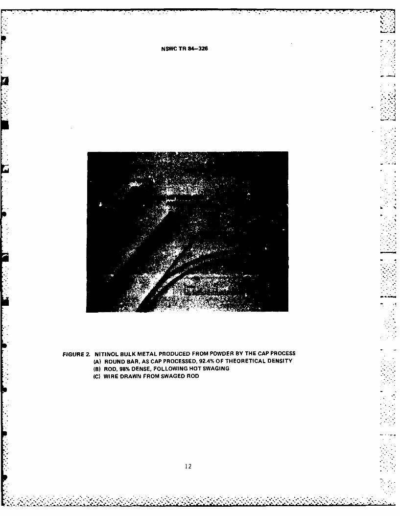
percent of TD or greater. This density can be hot worked in air. Figure 2A
presents the first bar of the three, as CAP processed. A rod hot swaged and
machined from the second bar, Figure 2B, and wire drawn from the third bar,Figure 2C, are also shown.
The three bars were made from -100 mesh Heat 81510 powders. After swaging
from an 850°C furnace to a 50 percent reduction in area, the density of thesecond bar increased to 98 percent of TD from its original "as CAP" density of91.5 percent TD. Wire was readily drawn from the third bar after it was hot
swaged to 6 mm (0.250 inch) in diameter and then cold swaged to 3.3 mm (0.130inch) in diameter with intermediate brief anneals at 600*C. The wire drawingwas done at 25*C, using 10 percent reductions in area, without lubrication ofthe wire. No breakage of the wire occurred, demonstrating that the CAP process
can produce a high quality of wire. The wire was reduced to 2.8 mm (0.111 inch)with intermediate anneals. This was a 28 percent reduction in area by wiredrawing. Subsequently the wire was reduced to 1.5 Vm (0.062 inch) in diameter
by a variety of treatments including intermediate annealing, refrigerating, -
swaging, and drawing. These latter were for the purpose of enhancing the shapememory response. Bend tests showed the swaged and drawn wire to perform as well
as cast and wrought wire in shape recovery.
Hot extrusion of bare CAP processed ingot was unsuccessful (due to "fir
tree" break-up) when done under the general conditions which are effective forcast NITINOL ingots. To demonstrate that CAP processed material would extrude
it was canned in a heavy wall steel container. Successful extrusion with an
11.6:1 reduction in area was achieved at 1065*C. The extruded rod and the CAPprocessed ingot from which its preform was cut are shown in Figure 3. Theconditions under which CAP processed NITINOL rod and tube can be extruded barewill require further investigation.
Final densification of preforms can be by hot extrusion. This is expected
to have a significant effect on production economies projected for thestraightline coupling and reducer parts, and little effect on other shapes.These latter shaped fittings would require that their ports be hot and/or cold
worked by swaging to size before machining to finished dimensions. Finaldensification of these parts can be done directly, without canning, by hotisostatic pressing or by isostatic pressing of the heated as CAP'd preform parts
contained in a crucible in a cold wall pressure chamber. 15
The economics of densification of CAP'd preforms of various shapes are
attractive in that batches of near net shape preforms can be densified in the
same way as is now done commercially for batches of castings. No canning of theparts is required, and the HIP furnace may be loaded to capacity, resulting in
low per piece cost. This process is an attractive method to completely densifyparts which are not to be subsequently hot worked.
1.1.l
.......... ... . . . . .. . . . . . . . . . . . . . . . . . . . . .
LiNSWC TR 84-326
4
FIGURE 2. NITINOL BULK METAL PRODUCED FROM POWDER BY THE CAP PROCESS(A) ROUND BAR, AS CAP PROCESSED, 92.4% OF THEORETICAL DENSITY(B) ROD, 98% DENSE, FOLLOWING HOT SWAGING(C) WIRE DRAWN FROM SWAGED ROD
12
. *. n

NSWC TR 84-326
EXTRUDED ROD
12" 2,r 3r"
FIGURE 3. CAP PROCESSED NITINOL AND EXTRUDED ROD(A) CAP PROCESSED NITINOL INGOT, 8 cm DIAMETER x 14 cm LENGTH,4.17 Kg (9.2 Ibs).(B A 7.5 cm LENGTH OF THE INGOT WAS USED TO PRODUCE THE EXTRUSION,2.2 cm DIAMETER x 80.5 cm LENGTH.
13/14
.~~ ~ ~ ~ ..

NSWC TR 84-326
CHAPTER 3
SHAPED PARTS PRODUCTION
Producing preforms of several different shapes, e.g., couplings, tees, andelbows, by the CAP process would establish the feasibility of production of thebroader range of pipe fitting shapes now in commercial usage. Other fittings,
for example, which appear in piping systems include reducers, crosses, halfells, caps, plugs, valves, flanges, and unions.
The nature of the CAP process is such that a variety of shapes and sizescan be sintered simultaneously. The different sized tubes shown in Figure 4A-Dwere produced singly using the CAP procedure as previously described. They
could have been produced simultaneously in a single crucible. The powder usedfor each preform was Heat 81510 in -100 mesh size.
The costs of producing shaped parts can be allocated as follows: cost ofthe elemental metals in the alloy; producing the alloy; atomizing; glass moldpreparation; loading, evacuating, and sintering the molds; secondary processing;and final machining. All of these operations, except mold preparation, havebeen performed on a commercial basis for other metals and are subject to Lestablished competitive forces. Mold making in glass for metal castings is anew process for which little guidance exists as to ultimate cost per part.Large-scale production of shapes will require fixturing of the glass lathes andthe automation of the hand operations currently used to produce shapes.
It is noted that a double wall glass tubular shape such as is used for a ........
coupling preform can be made in produc-ion for a few dollars. This is manifestby the u der $10 price at retail for evacuated and assembled domesticThermos bottles. Double wall glass shapes made in more limited production,such as laboratory vacuum traps, list for $25 each. Such a shape could producea 2-pound NITINOL tube sufficient to make five or six couplings (a $4 or $5contribution to the manufacturing cost).
The more complex glass shapes used to produce an ell or tee shape fittingare shown in Figure 5, as well as a tee produced from this style of double wallglass mold.
Figure 6A shows a drawing of double wall glass tube mold, and Figure 6B L
shows a tee, also in the Dewar style. Figure 6C shows a solid graphite rodsubstituted for the inner tube of the double wall tube design in Figure 6B.This concept offers several advantages in that it is simpler in principle thandouble wall tubes; it provides a smooth, dimensionally controlled inner wall
_ after CAP processing; the graphite rod provides good heat flow into the moldinterior during sintering; it is simple and easy to drill out after sintering;and it enables shapes with variable dimension internal cavities such as occur invalve bodies. Graphite cores are uniquely adapted to the CAP processing of
15
.*.- . .... .. *.X*-**.-%.......... . , .-.,..' ._" -... '.-.-.'.-' .. .. ;. .,".. " . . .. .. . .. .* . ...... ,.. ...-- : , .: .. -. .- , **.. -. **... .... .,***.. . s

NSWC TR 84-326
~ A
N itinol tubular preform, originally 2.2 x 3.3 x 12.7 cm,0.39 Kg (0.875 Ib). Shown is a section of the preform inthe "as CAP processed" condition after sandblast (A) anda machind setion cut from it (B).
d434
Nitinol tubular preform, 5 x 6 x 12.7 cm, 0.76 Kg (1.68thb).This is a thin wall (10:1 diameter to wall thickness). Tubularpreform is shown in the "as CAP processed" condition.
FIGURE 4. CAP PROCESSED NITINOL TUBULAR PREFORM$
16

NSWC TR 84-326
ii
II
(E)
Nitinol tubular preform 6.8 x 2.8 x 20.6 cm, 3.93 Kg (8.67 Ibs).This is a heavy wall (3:1 diameter to wall thickness).
(D) Tubular preform in the "as CAP processed" condition.(E) Machined sections as prepared for subsequent extrusion.
FIGURE 4. (CONTINUED) CAP PROCESSED NITINOL TUBULAR PREFORMS
17
. . -. ~o,...

NSWC TR 84-326
S
BEFORE CAP PROCESSING
(A) Glass molds filled with pre-alloyed NITINOL power ready forCAP processing .0
....... .
...
3.0
AFTER CAPPROCESSING
(B) NITINOL tee preform, after CAP processing, from glass mold shown in (A)
FIGURE 5. MOLDS FOR SHAPED-FITTINGS AND CAP PROCESSING NITINOL TEE
18
#. .,° .. ,."p . " . - . . . o . . . . . . • ° . * o . . o . . . ." . * . . . . , • , . .

NSWC TR 84-326
POWDERFILL &EVACUATION PORT
• - .--
I II II I
b I BOROSI LICATE GLASSI - DEWAR STYLE DOUBLEI WALL TUBULAR
I I
I
(A)
I POWDERFILL &
BOROSI LICATE GLASSDEWAR STYLE DOUBLE
fT WALL TEE
GRAPHITE CENTERING PIN
POWDERFILL &EVACUATION PORTGRAPHITE ROD
i""
GLASS NIPPLE FOR CEMENTEDGRAPHITE CENTERING PIN GRAPHITE B S A S
JITBOROSI LICATE GLASS ,'i'.JOINT
FIGURE 6. MOLD DESIGNS FOR HOLLOW SHAPES(A) DEWAR STYLE TUBULAR(B) DOUBLE WALL TEE(C) GRAPHITE CORE TEE
19
P . . . . . . . . . . .. . , . . . . .. .

NSWC TR 84-326
NITINOL, since no reaction between graphite and NITINOL occurs at the sintering*temperatures used. A tee mold and the as CAP'd tee, following the design shown
in Figure-6C, are shown in Figure 7.
I2

NSWC TR 84-326
--EVACUATION PORT
FILLED TEE GLASS MOLD
d OI ~~GAPI'ITE COiM ..
AS CAP'D NITINOL TEE
FIGURE 7. GRAPHITE-CORE TEE MOLD AND AS CAP'D NITINOL TEE. END OF THE TEE "CROSS BAR" HASBEEN CUT OFF TO EXPOSE GRAPHITE CORE. NOTE THAT THE CORE WILL PRODUCE A UNI-FORM INNER DIAMETER WHEN DRILLED OUT. GRAPHITE IS READILY MACHINABLE.
21/22
. '1** b b * * **. . . . . . . . . -.
"-." ".""" . " '.,.- :,..L -. '",L . . ... """"-.. " "- "-" ". ", ,- "•". ." ' ". , ,.:.-' : . , .-.- =',:,'. .. '=

NSWC TR 84-326
CHAPTER 4
CONCLUSIONS
The following conclusions were derived from this study:
I. NITINOL alloy shaped products can be successfully made by theConsolidation by Atmospheric Pressure (CAP) process. This study emphasized rod,and hollow shapes such as are found in piping systems. It is concluded from thesuccess in producing these shapes that other useful solid and hollow shapescould also be produced by the CAP process. Such near net shape parts previouslyconsidered not feasible by casting could include low noise propeller blades,cryogenic service devices, non-magnetic tools, and compromise-resistantcarbide/NITINOL composite components for locks. In general the utility of theCAP process, when combined with graphite inserts, enables manufacture of shapespreviously precluded due to the difficulty of casting them.
2. Hollow tubes and tees were successfully made. The solid rod producedwas shown to be of good quality and was subsequently extruded, swaged, and drawn.
3. An essential parameter for part production is the use of -100 meshpre-alloyed powder. CAP processing should be at 1175*C for a minimum of 4hours. This yielded a minimum of 91.5 percent of theoretical density (TD).Further densification can be achieved by other methods, e.g., hot isostaticpressing, extrusion, swaging, or hot rolling as dictated by the part shape.
4. Thin wall and thick wall tabular preforms of a wide range of diameterscan be made by the CAP process.
5. The nature of the process enables short turnaround time for the
production of finished parts after the atomized powders are produced and are"shelf items."
23/24
.. . . . . . . . .. . ... . -
• -. j . . . . " . . . -*.. = ' ' " . " . . ° ,ot ' ." .. - . " , " -,° ° ' " .°.. ' ' ' .. ,,°. = ' ' % ' '

NSWC TR 84-326
CHAPTER 5
RECOMMENDATIONS
The proof of process and manufacture of prototype shaped parts has beencompleted. It is recommended that the development program be extended as amanufacturing technology program.
Among the topics which should be addressed under a scaled up and moreadvanced technology development of the CAP process are the following:
* alloy selection via powder blending
* optimized shape memory response
* determination of mechanical properties
* optimized extrusion parameters
0 economics of various production techniques, before, during, and after
CAP processing
a installation techniques of multi-port pipe fittings and pressure testsof assemblies of fittings and piping.
25/264

NSWC TR 84-326
REFERENCES
I. Evaluation of NITINOL Fittings for Joining Titanium Piping for ShipboardApplications, Lockheed Missiles & Space Company, Inc. Report, LMSC-D350045,Apr 1973.
2. Wren, R. F., and Jones R. W., Nickel-Titanium Pipe Couplings for SubmarinePiping Systems, General Dynamics Task 5.41-1, Jun 1975, Contract No.
0024-75-C-2026 (Limited Distribution).
3. Keible, Edward A., Jr., "Cryofit Pipe and Tubing Joining System," inProceedings of the Sixth Submarine Hydraulics Conference, 13 Nov 1975, . .Washington, DC.
4. Caskey, Maurice, R., and Embry, Gerald D., "Use of Heat RecoverableCoupling Technology in Shipyard Production," Naval Engineers Journal,
Apr 1979, pp. 45 to 59.
5. Liberator, Donald J., Baskerville, James E., "The Introduction of HeatRecoverable Couplings to Ship Repair and Maintenance," Shipbuilding andRepair Symposium, American Society of Naval Engineers, 17-18 Sep 1981.
6. NAVSEA Itr 07PM2/DS Ser 20 of 25 Mar 1982 to SEA 07 (Limited Distribution).
7. Eckelmeyer, K. H., The Effect of Alloying on the Shape Memory Phenomenon in
Nitinol, Sandia Laboratories, SAND 74-0418, Mar 1975.
8. Van Cleave, David A., "Cold Pressing Opens the Door on Complex Shapes,"Iron Age, Vol. 219, No. 18, 9 May 1977, pp. 39 to 41.
9. Chandler, Harry E., "New Directions for Nonferrous Metals," Metal Progress,Vol. 125, No. 7, Jun 1984, p. 29.
10. Goldstein, David M., and McNamara, Leo J., Proceedings of the NITINOL HeatEngine Conference, NSWC MP 79-441, 27 Sep 1978.
11. "Manufacturing Technology Ships Overhaul Investment Opportunity Study,".
Navy Manufacturing Technology Bulletin, No. 83, Sep 1980.
12. Baskerville, James E., Whiddon, W. David, "Ship Design--Performance ThroughInnovatLon," Naval Engineers Journal, Feb 1981, pp. 33 to 44.
27 -'
. * .. •.. .•"""' . " ."",".* ,."." "- ."-,'-"-":.'.<*. '-"." "-"'". ."....'".. . ... ,--"".,"."..".".".",.,. .-.- ': "*" "-

TV..
NSWC TR 84-326
REFERENCES (Cont.)
13. NAVSEA ltr 90M/RR Ser 168 of 9 Nov 1981 to CNM.
14. Black, Herbert L., Somerville, Mark, Schwertz, Jerome, "Powder Metallurgy."US. Patent No. 4,227,927, 14 Oct 1980.
15.GolstenDavid M., "Method of Compacting Powders," U.S. Patent
28

NSWC TR 84-326
DISTRIBITION
Copies Copies
Commander Office of Naval Research
Naval Air Systems Command Attn: Code 431 (S. Fishman)
Attn: Code 320A (R. Schmidt) 1 Materials DivisionWashington, DC 20361 800 North Quincy Street
Arlington, VA 22217-5000
CommanderNaval Air Development Center Office of Deputy Under SecretaryAttn: Code 606D (G. London) 1 of Defense for Research and
Warminster, PA 18974 Engineering %%Attn: J. Persh
Commander Staff Specialist for Materials
Naval Sea Systems Command and StructuresAttn: SEA 62R4 (M. Kinna) 1 Room 3DI089
PMS 393 (C. Kresge) 1 The PentagonPMS 393-A23 (Chuck Kresge) I Washington, DC 20301PMS 400-D4
(LCDR J. E. Baskerville) 1 Defense Technical Information
Code 05R25 1 CenterCode 05R4 (3. Freund) 1 Cameron StationCode 05R4 (Walt Kollar) 1 Alexandria, VA 22314 12Code 05R4 (Tom Galley) 1Code 05M2 (J. Forney) I Defense Advanced Research
' Code 56Y23 (John Conway) i Project AgencyCode 56Y23 (Susan Yang) 1 Attn: P. Parrish ICode 56Y23 (G. D. Giovanni) 1 Materials Sciences DivisionCode 62R (W. W. Blaine) 1 1400 Wilson BoulevardCode 913B (Jesse Atkins) 1 Arlington, VA 22209
Washington, DC 20362U.S. Army Research Office
Naval Material Command Attn: G. MayerAttn: MAT 0725 (J. Kelly) 1 Associate Director,
MAT 064 (. Mclnnes) 1 Metallurgy and Materials
*Department of the Navy Science DivisionWashington, DC 20360 P. 0. Box 12211
Triangle Park, NC 27709
CommanderDavid W. Taylor Naval Ship Library of Congress
Research and Development Attn: Gift and Exchange Div. 4Center Washington, DC 20540
Attn: Code 28141 (J. Gudas) IAnnapolis, MD 21402
D (1)

NSWC TR 84-326
DISTRIBUTION (Cont.)
Copies Copies
Department of Energy Dynamet TechnologyAttn: Code CE142 (Marvin Gunn) Attn: Stanley Abkowitz I1000 Independence Avenue, S.W. Eight A Street
Washington, DC 20585 Burlington, MA 01803
Sandia National Laboratory General Dynamics ElectricAttn: Div 1822 Boat
(Dr. K. Eckelmeyer) 1 Attn: Norman James
Div 1832 Dept. 457(Dr. R. Salzbrenner) i Eastern Point Road
Albuquerque, NM 87185 Groton, CO 06340
Norfolk Naval Shipyard Grumman Aerospace Corporation
Attn: Code 214 (Oscar Mullican) 1 Attn: Mr. Fancher WakefieldNorfolk, VA MS B15-35
Bethpage, NY 11714
Battelle -
Columbus Laboratories Ingalls ShipbuildingAttn: Dr. Curtis M. Jackson 1 Corporation
505 King Avenue Attn: MS 1090-03 (Gerald Embry) I
Columbus, OH 43201 MS 1011-16 (Maurice Caskey) 1MS 1090-04 (Gil Graves) 1
Brook Haven National Laboratory P.O. Box 149
Attn: L. E. Kukacka Pascagoula, MS 39567Department of Applied
° Science/PSD Kimble Division of Owens
- Bldg. 526 IllinoisUpton, NY 11973 Attn: Don Gagnon 1
1 Seagate
University of Illinois at Toledo, OH 43666Urbana-Champaign
Attn: Marvin Wayman 1 McDonnell Douglas CorporationCollege of Engineering Attn: J. L. McNichols
Department of Metallurgy 5301 Bolsa Avenueand Mining Engineering Huntington Beach, CA 92647
Urbana, IL 61801Memory Metals
Cory Laboratories, Inc. Attn: Dr. L. M. Schetky
Attn: Dr. J. Cory 1 652 Glen Brook Road1436 View Point Avenue Stamford, CO 06906Escondido, CA 92027
Newport News ShipbuildingCYTEMP Division Attn: Code E71Cyclops Corporation (Mr. John Redpath) IAttn: R. Gasior 3 4101 Washington AvenueBldg. V-2 Newport News, VA 23607
Mayer Street
- Bridgeville, PA 15017
(2)
. ... .

NSWC TR 84-326
DISTRIBUTION (Cont.)
Copies Copies
Quantex Engineering Rockwell InternationalAttn: Peter Hochstein Rocketdyne Division28600 Lorna 6633 Canoga AvenueWarren, MI 48092 Canoga Park, CA 91340 1
Raychem Corporation Special Metals CompanyAttn: P. Robert I Attn: Dave Williams 1
J. P. Hine 1 Middle Settlement RoadK. Melton I New Hartford, NY 13413Dr. Jack Harrison 1
300 Constitution Drive Internal Distribution:Menlo Park, CA 94025 R32 (D. Goldstein) 50
R04 (D. Love) I
Ridgway Banks E22 (D. Johnston) 1RM Banks and Associates C. McKnight I1455-1 E. Francisco Boulevard E231 9San Rafael, CA 94901 1 E232 3
TJ I
(3)-