sar chapter 10 auxiliary systems - arpansa.gov.au · sar chapter 10 auxiliary systems prepared by...
TRANSCRIPT

Document Number: RRRP-7225-3BEAN-001-REV0-CHAPTER-10 Revision: 0
Replacement Research Reactor Project
SAR CHAPTER 10 AUXILIARY SYSTEMS
Prepared By
For Australian Nuclear Science and Technology Organisation
1 November 2004
Page 1 of 76

INVAP ANSTO Australian Nuclear Science & Technology Organisation
SAR - CHAPTER 10
File Name: RRRP-7225-EBEAN-002-REV0-Ch10.doc Page 2 of 2 Revision: 0 1 november 2004
ANSTO Document N°: RRRP-7225-EBEAN-002-Rev0-CHAPTER-10 Revision: 0
Replacement Reactor Project Document Title: SAR - CHAPTER 10, Auxiliary Systems
REVISION SHEET Ref No:
Print name, date and sign or initial Revision Description of Revision Prepared Checked/
Reviewed Approved
0 Original issue for public release MS RM GW
Notes: 1. Revision must be verified in accordance with the Quality Plan for the job.

INVAP RRR SAR ANSTO Auxiliary Systems
Table of Contents
File Name: RRRP-7225-EBEAN-002-REV0-Ch10.doc Table of Contents - 1
10 AUXILIARY SYSTEMS
10.1 Fuel Storage and Handling System 10.1.1 Introduction 10.1.2 System Categorisation 10.1.3 Safety Functions 10.1.4 Reference Documents, Codes and Standards 10.1.5 Fresh Fuel Storage and Handling System 10.1.6 Spent Fuel Storage and Handling System 10.1.7 Design Evaluation
10.2 Fire Protection 10.2.1 Introduction 10.2.2 The New South Wales Fire Brigade 10.2.3 System Categorisation 10.2.4 Fire Loads 10.2.5 Fire Zones 10.2.6 Automatic Fire Detection 10.2.7 Automatic Fire Sprinkler Systems 10.2.8 Wall Wetting Sprinklers 10.2.9 Medium Velocity Water Spray Systems 10.2.10 Water Supply 10.2.11 Testing and Commissioning 10.2.12 Gaseous Fire Suppression Systems 10.2.13 Portable Fire Extinguishers 10.2.14 Smoke Exhaust 10.2.15 Essential Power 10.2.16 Emergency Lighting and Exit Signs 10.2.17 Passive Systems 10.2.18 Emergency Planning and Training 10.2.19 Bush Fire Control
10.3 Communications 10.3.1 General 10.3.2 Voice Communication Systems 10.3.3 Emergency Warning System 10.3.4 Plant Visual Surveillance System 10.3.5 Reactor Facility Local Area Data Network
10.4 Heating, Ventilation and Air Conditioning Systems 10.4.1 Introduction 10.4.2 Emergency Control Centre Ventilation and Pressurisation System 10.4.3 Emergency Control Centre Air Conditioning 10.4.4 Main Control Room Air Conditioning 10.4.5 Auxiliary Instrument Room Air Conditioning 10.4.6 Loading Hot Cell Ventilation 10.4.7 Fume Exhaust 10.4.8 Active Area Exhaust 10.4.9 Reactor Building Non-Containment Air Conditioning and Ventilation 10.4.10 Reactor Building Containment Air Conditioning and Ventilation 10.4.11 Non-Reactor Buildings 10.4.12 Central Energy Systems
10.5 Compressed Air 10.5.1 Introduction 10.5.2 System Categorisation 10.5.3 Design Basis

INVAP RRR SAR ANSTO Auxiliary Systems
Table of Contents
File Name: RRRP-7225-EBEAN-002-REV0-Ch10.doc Table of Contents - 2
10.5.4 Circuit Description 10.5.5 Breathing Air System 10.5.6 Instrumentation 10.5.7 Surveillance, Inspection and Testing 10.5.8 Evaluation
10.6 De-mineralised Water Supply 10.6.1 Introduction 10.6.2 System Categorisation 10.6.3 Design Requirement 10.6.4 Description
10.7 Gas Services system 10.7.1 Introduction 10.7.2 System Categorisation 10.7.3 Description
End of Table of Contents

INVAP RRR SAR ANSTO Auxiliary Systems
Fuel Storage and Handling System
File Name: RRRP-7225-EBEAN-002-REV0-Ch10.doc 10.1-1
10 AUXILIARY SYSTEMS
The objectives for SAR Chapter 10 are as follows: 1. To identify the specific safety requirements and safety design bases applicable to the
auxiliary systems.
2. To provide a summary description of the design and operation of the auxiliary systems.
3. To identify the safety features of the auxiliary systems that contribute to nuclear or personnel safety.
4. To evaluate the design and operation of the auxiliary systems so as to demonstrate that they meet the identified safety requirements and safety design bases.
5. To identify faults that are subject to detailed safety analysis in Chapter 16.
10.1 FUEL STORAGE AND HANDLING SYSTEM
10.1.1 Introduction
This Section presents a description and safety assessment of the Fuel Storage and Handling System, which is the overall set of rooms, structures and components necessary to store and handle fresh or spent Fuel Assemblies (FAs) described in Chapter 5 (Section 5.3).
The Fuel Storage and Handling System comprises two different sub-systems: a) Fresh Fuel Storage and Handling System
Includes all the structures and components that allow fresh fuel assembly management from the time FAs enter the Reactor Facility building to when they are loaded into the Core.
b) Spent Fuel Storage and Handling System
Includes all the structures and components that contribute to irradiated FA management from when they are withdrawn from the Core, to the time they are positioned in the Service Pool for storage, until their shipment off-site.
The design of both systems was performed according to the guidelines of the Nuclear Regulatory Authority of Argentina (ARN), internationally accepted criteria for safe nuclear fuel storage and handling, and ARPANSA guidelines. Both systems were designed to perform during normal operational conditions and under postulated design basis accident conditions.
A computer database allows the tracking of all FAs in the facility. FAs are identified by an engraved code number on their side plates and on the top surface of the handling pin. Since some FAs in the first cores have uranium contents lower than normal FAs, the criticality calculations performed using the nominal values are conservative for those FAs. This allows the treatment of all FAs in the same manner.
All spaces in racks and containers that can be occupied by fuel assemblies have a clearly marked position identification that, together with the above-mentioned database, allows easy location of FAs.
ANSTO is committed to fulfilling all the applicable regulatory requirements to obtain approvals to transport spent fuel off-site in appropriate transport casks. Such operations

INVAP RRR SAR ANSTO Auxiliary Systems
Fuel Storage and Handling System
File Name: RRRP-7225-EBEAN-002-REV0-Ch10.doc 10.1-2
are expected to be performed every 5 to 8 years and the plant has all the facilities needed to carry out the procedures with the minimum risk.
10.1.2 System Categorisation
System Safety Category Seismic Category Quality Category
Fresh Fuel Assembly Storage
2 1 B
Irradiated Fuel Assembly Storage in
Reactor Pool
2 1 B
Irradiated Fuel Assembly Storage in
Service Pool
2 1 B
Irradiated Fuel Storage Supports
2 1 B
Definitions of Safety, Seismic and Quality categories are included in Chapter 2.
10.1.3 Safety Functions
The safety functions of the fuel storage systems are: a) Prevention of inadvertent criticality or transients of unacceptable reactivity.
b) Prevention of spent Fuel Assembly (FA) damage.
c) To provide protection to operators from radiation during storage and handling of fresh and irradiated FAs.
d) Prevention of contamination spread in the case of fuel damage.
10.1.4 Reference Documents, Codes and Standards
“Criteria for the design of nuclear installations” ARPANSA Regulatory Guideline RG-5, draft, 23/12/1998
ISO 1709:1995(E) “Nuclear energy – fissile materials – Principles of criticality safety in storing, handling and processing”.
Normas Regulatorias República Argentina. Serie AR-4. Autoridad Regulatoria Nuclear (ARN). (Regulations for the Argentine Republic. AR-4 Series. Argentine Nuclear Regulatory Authority.) (1998).
MCNP-4C. RSICC Computer Code Collection. CCC-700. Oak Ridge National Laboratory. Used for criticality calculations.
10.1.5 Fresh Fuel Storage and Handling System
10.1.5.1 Introduction
The FAs described in Chapter 5, Section 5.3, have identification code numbers engraved on their side plates and on the handling pin that allow tracking while they are in the facility. This traceability is maintained through the use of the fuel database where specific fuel data plus location identification are loaded and modified as appropriate by authorised staff.

INVAP RRR SAR ANSTO Auxiliary Systems
Fuel Storage and Handling System
File Name: RRRP-7225-EBEAN-002-REV0-Ch10.doc 10.1-3
The Fresh Fuel Storage and Handling System comprises all structures and components that contribute to fresh fuel management, from the time the FA enters the Reactor Facility building up to the moment it is loaded into the Core.
Operating procedures are utilised in the handling of fresh FAs. A brief description of the sequence of operations follows:
a) Fresh FAs are brought into the Reactor Facility building and are transported in a container that complies with applicable regulations. Every FA is packaged individually in its own protective container.
b) FA’s are then moved to the Fresh Fuel Storage Room.
c) Administrative procedures are followed and data for each FA is loaded into the FA database. This includes the location assigned in the Fresh Fuel Storage Room.
d) FAs are transported to the Reactor Hall through the Safety Access System (SAS) and are finally stored, in their protective casings, in the Fresh Fuel Storage Room.
e) During refuelling operations fresh FAs are carried to the Reactor Pool area. There, the FAs are taken out of their boxes and inspected prior to their loading in the Core. To allow the loading of fresh FAs, the reactor must be in Refuelling Mode (operational status that sets up the Reactor Control and Monitoring System (RCMS), Reactor Protection System (RPS) and Post Accident Monitoring (PAM) system instruments accordingly) and the relocation of the remaining FAs in the core must have been finished (i.e. vacant positions in the Core grid are ready to be occupied by the fresh fuel).
f) The loading of FAs into the core is done from the Operation Bridge with the aid of the FA Tool.
g) Once in place in the core, the FAs are fastened.
10.1.5.2 Design Bases
The Fresh Fuel Storage is designed according to the following design bases: a) The system allows easy and safe storage and handling of fresh FAs.
b) The system ensures secure storage of fresh FAs.
c) The occurrence of criticality is prevented under normal and accident conditions.
d) The following criterion is verified: Keff ′ 0.9 for normal operation and accident conditions.
Additionally, the design complies with the following technical design basis: a) FAs are stored to facilitate ease of handling.
b) The structure is divided into modules to allow easy mounting and dismounting.
c) The pitch between FAs ensures sub-criticality.
d) The storage structure takes account of the mechanical loads of the stored FAs.
e) The storage structure fulfils the requirements for seismic tolerance according to Seismic Category 1.

INVAP RRR SAR ANSTO Auxiliary Systems
Fuel Storage and Handling System
File Name: RRRP-7225-EBEAN-002-REV0-Ch10.doc 10.1-4
10.1.5.3 Fresh Fuel Storage Room and Rack
The Fresh Fuel Storage Room is designed to allow safe and secure storage of the FAs that enter the Reactor Facility building until they are moved to the Reactor Pool to be loaded into the core. The storage room is accessed from the Reactor Hall.
Physical security arrangements for fresh FAs subject to the satisfaction of Australian Safeguards and Non-Proliferation Office are in place.
The storage rack is a steel structure in the form of a lattice, fixed to the wall. Each lattice cell is a compartment sized to contain one FA in its protective casing. The arrangement ensures that fresh FAs are maintained at fixed positions and prevents their moving closer to each other. FAs are held in position in the storage racks by a locking bar.
The rack geometry guarantees the Keff values specified in the design basis without the need for neutron absorbers in the racks.
The rack structure is designed to support the FA load under seismic conditions according to its Seismic Category 1 classification. In addition, the room itself, being a part of the Containment, is also classified as Seismic Category 1.
The Emergency Make-up Water System (EMWS) Tanks and related piping located close to this room are classified as Seismic Category 1 and hence they are designed to bear the SL-2 earthquake without leaking any water. In addition, the room has a threshold (50 mm) that prevents water entry from any spill in the Reactor Hall.
10.1.5.3.1 Fresh Fuel Storage Criticality Calculations
The objective of these calculations is to determine the geometric conditions necessary to maintain sub-criticality in Reactor Facility Fresh FA Storage. The analysis describes the Fresh FA Storage criticality calculation for several situations, some of which correspond to normal conditions and some to accident conditions such as floods.
The criterion to define that a given storage configuration is safe requires the Effective Multiplication Factor (Keff) to be lower than 0.9 (Keff < 0.9) for normal and accident conditions.
Fuel was considered to be fresh at room temperature (200C) and without burnable poison.
The calculations have been performed using "state of the art" methods. In particular, the MCNP-4C Code from the RSICC Computer Code Collection (CCC-700) of the Oak Ridge National Laboratory, which is based on Monte Carlo methods, was used. This code has been widely and internationally validated, including by INVAP which has validated it against critical measurements on the ETRR-2 Reactor.
All cases analysed were considered finite (3D) with a full description of the storage rack including the concrete walls of the Fresh FA Storage Room. . The actual length of the FA (active length and top and bottom frames) was represented in all the calculation models. The container length was assumed to be the same as the FA total length.
The following cases were considered to account for different operational and abnormal situations:
a) FA’s in their rack compartments, inside their aluminium boxes surrounded by air.
b) FA’s in their rack compartments inside their aluminium boxes, rack and room completely flooded.

INVAP RRR SAR ANSTO Auxiliary Systems
Fuel Storage and Handling System
File Name: RRRP-7225-EBEAN-002-REV0-Ch10.doc 10.1-5
c) FA’s in their rack compartments inside their aluminium boxes, rack and room flooded with different water level.
d) FA’s in their rack compartments, inside their aluminium boxes, considering a 20 cm thick water wall representing a workman standing in front of the rack.
e) Collapse simulation. Array of FA’s in their rack compartments, inside their aluminium boxes, surrounded by air. Aluminium boxes touching each other.
The results are summarised in Table 10.1/1.
It can be seen that with the FAs properly placed in the rack, not even a flood would raise the Keff above the maximum allowed value. Similarly, piling FAs on the floor without their boxes also does not lead to criticality. Therefore all the fresh FAs placed in the rack, one in each compartment, constitute a safe arrangement from a criticality viewpoint.
10.1.6 Spent Fuel Storage and Handling System
10.1.6.1 Introduction
The Spent Fuel Storage and Handling System comprises all the structures and components that contribute to spent fuel management, from the time spent FAs are withdrawn from the Core until they are placed in the Service Pool for long term storage.
The spent fuel storage racks have capacity for at least 10 years reactor full power operation. Before the racks are filled, however, spent fuel would be loaded into a transport cask and shipped off-site and the building has been designed accordingly. This is expected to occur only every 5-8 years and a proper safety analysis for these operations would be produced at the time of preparation for the shipment.
The components of the Spent Fuel Storage and Handling System, some of which are shared with other systems, are:
a) Reactor Pool Fuel Storage Rack
b) Operation bridge
c) Transfer canal
d) Service Pool Spent Fuel Storage Rack
e) FA Tool
f) Floor access hatch #9
The main spent fuel operations are performed with the reactor in Refuelling Mode (RCMS, RPS and PAM equipment are set appropriately). The planned sequence of operations is as follows:
a) Spent FAs are removed from the Core at the end of each operating cycle. Each FA belongs to a fuel “chain” (the set of positions involved in each refuelling relocation) defined in the Core refuelling strategy.
b) Spent FAs removed from the Core are temporarily placed in the Reactor Pool Storage Rack to decay for approximately one month.
c) After one cycle in the Reactor Pool Storage Rack the spent FAs are transferred under water one at a time through the transfer canal to the Service Pool Storage Rack. FA identity is verified from the code numbers on the handling pin and the rack position.

INVAP RRR SAR ANSTO Auxiliary Systems
Fuel Storage and Handling System
File Name: RRRP-7225-EBEAN-002-REV0-Ch10.doc 10.1-6
d) The transfer operation is done from the Operations Bridge with the FA tool. The bridge is moved from a position above the Reactor Pool to a position above the Service Pool.
10.1.6.2 Design Bases
The Spent Fuel Storage and Handling System design complies with the following safety design bases:
a) The system allows easy and safe storage and handling of irradiated FAs.
b) The occurrence of criticality is prevented under normal and accident conditions.
c) The following criterion is verified: Keff ∗ 0.9 for normal operation and accident conditions.
d) The radiation dose rate produced at the pool lateral wall and operation bridge by the FAs in storage must not exceed the target dose rate of 1 µSv/h-1 (derived from the reactor facility design objective of <2 mSvy-1 which is stated in Chapter 12, Section 12.1, and assuming radiation workers work 2000 hours in a year with an occupancy factor of 1).
e) The radiation dose rate produced by spent FAs in transit from the Reactor Pool to the Service Pool must not exceed 10 µSvh-1 at the operation bridge (in normal conditions).
Additionally, it complies with the following technical design basis: a) There are two storage racks, one inside the Reactor Pool for short-term storage of FAs and the other inside the Service Pool for longer term storage of FAs.
b) FAs are stored vertically in such a way that their handling is simple and heat dissipation is enhanced.
c) The storage structure is properly shielded to minimise operator dose (shielding vertically above by pool water, shielding horizontally and vertically below by high density concrete).
d) The pitch between elements is appropriate to ensure sub-criticality in conjunction with cadmium inserted into the stainless steel structure.
e) The storage structure provides the required support for the loads produced by the stored FAs.
f) The structure fulfils the requirements for seismic tolerance according to Seismic Category 1.
10.1.6.3 Reactor Pool Spent Fuel Storage Rack
The Reactor Pool Spent Fuel Storage Rack is a stainless steel lattice structure that can hold FAs maintaining a fixed distance between neighbouring FAs. It allows storage of a complete core plus the three FAs decaying from the previous refuelling and still leave vacant positions.
The spent FAs are placed inside steel-and-cadmium baskets. Each basket can accommodate four FAs.
The cadmium layer depletion is negligible in both reactor and Service Pool storage racks.

INVAP RRR SAR ANSTO Auxiliary Systems
Fuel Storage and Handling System
File Name: RRRP-7225-EBEAN-002-REV0-Ch10.doc 10.1-7
The rack structure is designed to prevent breakage of the FAs as well as preventing their toppling out onto other reactor structures in case of seismic events, according to its Seismic Category 1 class.
The rack is used to hold spent FAs removed from the core for approximately 30 days (one fuel cycle), to allow fuel decay before transfer to the Service Pool. Its capacity also allows storage of a full core load of 16 FAs in case the core is required to be disassembled.
The possibility of storage of more than one FA per position is negligible due to the dimensions of the FAs and operational procedure restrictions.
10.1.6.3.1 Reactor Pool Spent Fuel Storage Rack Criticality Calculation
The criticality calculations were performed by means of code MCNP. The calculation model includes a full description of the RPSFASR placed in the light water tank. The heavy water tank and the heavy concrete reactor block are included in the calculation model.
The following conservative assumptions are used: a) No burnup.
b) No burnable poisons.
c) No impurities in the FA.
d) No U234.
All FA’s were considered fresh and at room temperature (20 8C).
Table 10.1/2 shows that the Effective Multiplication Factor be lower than 0.9 (Keff ∗ 0.9) for normal conditions is fulfilled by the design.
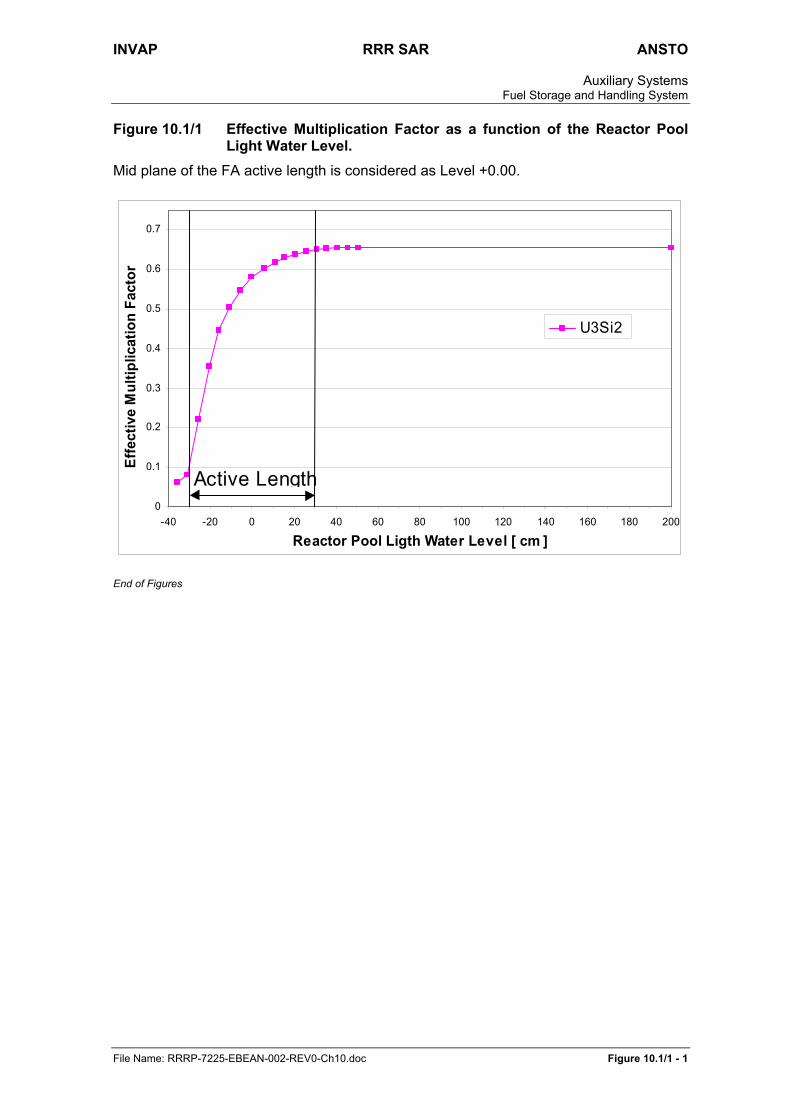
An accidental condition where the light water level varies in the Reactor Pool is calculated. Figure 10.1/1 shows the Effective Multiplication Factor as a function of the light water level. The Effective Multiplication Factor is lower than 0.9 (Keff ∗ 0.9) for this abnormal condition.
The maximum expected value for the Effective Multiplication Factor taking into account the Cadmium depletion, the bias of the FA Uranium loading and the bias of the FA mechanical tolerances is lower than 0.9. Table 10.1/3 shows the maximum expected value for the Keff.
10.1.6.4 Service Pool Spent Fuel Storage Rack
The Service Pool Spent Fuel Storage Rack provides long term storage for spent FAs, with an identical cell and basket design as that of the Reactor Pool Spent Fuel Storage Rack. The capacity of this rack is sufficient to store the spent FAs generated during 10 years of full-power reactor operation plus one full core.
The spent FAs are placed inside steel-and-cadmium baskets. Each basket can accommodate four FAs.
The possibility of storage of more than one FA per position is negligible due to the dimensions of the FAs and operational procedure restrictions.
The racks are Seismic Category 1, so can withstand a SL-2 earthquake without causing damage to FAs or allow them to fall out onto other structures.

INVAP RRR SAR ANSTO Auxiliary Systems
Fuel Storage and Handling System
File Name: RRRP-7225-EBEAN-002-REV0-Ch10.doc 10.1-8
10.1.6.4.1 Service Pool Spent Fuel Storage Rack Criticality Calculation
The criticality calculations were performed by means of code MCNP. The calculation model includes a full description of the SPSFASR. The Service Pool liner and the heavy concrete reactor block are included in the calculation model.
The following conservative assumptions are used: a) No burnup.
b) No burnable poisons.
c) No impurities in the FA.
d) No U234.
All FA’s were considered fresh and at room temperature (20 ºC).
Table 10.1/4 shows that the condition for the Effective Multiplication Factor to be lower than 0.9 (Keff < 0.9) for normal conditions is fulfilled.
An accidental condition where the light water level varies in the Reactor Pool was calculated. Figure 10.1/1 shows the Effective Multiplication Factor as a function of the light water level. The Effective Multiplication Factor is lower than 0.9 (Keff < 0.9) for this abnormal condition.
The maximum expected value for the Effective Multiplication Factor taking into account the bias of the FA Uranium loading and the bias of the FA mechanical tolerances is lower than 0.9. Table 10.1/5 shows the maximum expected value for the Keff.
10.1.6.5 Management of Damaged Fuel
Should any fuel plate, whether in the reactor core or in the storage racks, have its aluminium cladding perforated then some fission products could be released from the fuel into the pool water. Such releases would be readily detected by the Failed Fuel and Irradiation Target Monitors. These monitors are based on measuring delayed neutron activity in the pool water (see Chapter 8, Section 8.7.3). They monitor the water in the PCS and RSPCS flows respectively
There is also an Active Liquid Monitor (ALMO) (see Chapter 8, Section 8.7.3) that provides a diverse indication of abnormal levels of activity in the pool in the unlikely event a failure of a fuel plate were to occur.
The damaged fuel would be identified using appropriate procedures and, if necessary, unloaded from the core. It would be transferred to the Service Pool and placed in a special storage canister for storage and monitoring. The canister is designed to prevent dispersion of fission products that may be released by the damaged fuel and it fits into the Service Pool storage rack. In this respect it should be noted that once a leaking fuel plate has been removed from the core and its temperature has dropped to Service Pool temperature the release rate usually drops abruptly.
10.1.7 Design Evaluation
10.1.7.1 Prevention of Criticality
The fuel storage facilities provide a safe location for FAs, preventing the occurrence of inadvertent criticality. This is demonstrated by the criticality analysis, which was performed with a validated code according to accepted criteria.

INVAP RRR SAR ANSTO Auxiliary Systems
Fuel Storage and Handling System
File Name: RRRP-7225-EBEAN-002-REV0-Ch10.doc 10.1-9
The geometrical arrangements have been designed to prevent double batching. In the case of spent fuel storage, the use of a neutron poison (cadmium) embedded in the structure allows reduction in the pitch and consequently the volume occupied by the racks.
The criticality analysis shows that the design complies with the criticality criterion of: Keff ∗ 0.9 for normal operation.
The possibility for degradation of structural materials used in spent fuel storage racks (stainless steel and cadmium) is considered negligible due to the high quality of the pool water and the almost-zero neutron flux.
For the fresh fuel storage, the room that holds the racks has been designed to prevent entrance of water and to withstand a SL-2 earthquake (seismic category 1). Even if this room is flooded, the results (Table 10.1/1) show that the Keff criterion is still fulfilled.
10.1.7.2 Seismic Integrity of Stored Fuel Assemblies
Structural integrity of the storage racks under the most demanding loads has been demonstrated by a seismic design.
The components included in this system fall into the following two categories: a) Seismic Category 1: Items within this category shall be designed or demonstrate
to withstand the consequences of ground motions associated with earthquake level SL-2 (Seismic Level 2, also denoted as Safe Shutdown Earthquake).
b) Seismic Category 2: Items within this category shall be designed or demonstrate to withstand the consequences of ground motions associated with earthquake level SL-1 (Seismic Level 1, also denoted as Operational Basis Earthquake).
The category assigned to every component can be seen in Chapter 2, Section 2.5.
The seismic stress evaluation was performed followed the recommendations of IAEA and USNRC about design criteria for the resistance against seismic hazard (see Chapter 2, section 2.6.1). It was applied to the design of the FA storage structures resulting of detailed engineering stage, and considered:
a) The acceleration spectra for the building positions where systems are fixed
b) consideration of the fixing characteristics
c) stress evaluation in components and fixing points
This seismic analysis is part of the stress analysis performed for the system. The purpose of this analysis is:
a) To verify that the designs of the structures of the FA storage racks meet the requirements of the ASME B31.1 Code as regards stress including seismic loads.
b) To verify that the loads imposed on the system including those to the seismic event are below the allowable ones.
The Applicable code is ASME Boiler and Pressure Vessel Code.
10.1.7.2.1 Fresh Fuel Assembly Storage
The analysis was performed with the NASTRAN code.

INVAP RRR SAR ANSTO Auxiliary Systems
Fuel Storage and Handling System
File Name: RRRP-7225-EBEAN-002-REV0-Ch10.doc 10.1-10
10.1.7.2.1.1 Hypotheses of the analysis
The main hypotheses used in this analysis are: a) The FAs are included as non-structural mass.
b) The rack is bound by bolts to the wall and floor of the room.
c) The door was modelled as fixed at the hinge and locking points.
d) The combination of responses resulting from the three-seismic directions was carried out in a simplified and conservative way by means of a linear sum of actions.
e) The structure was analysed by means of the static method.
10.1.7.2.1.2 Input Data
The basic input data used in this analysis consists of: a) Dimensions, geometry and design characteristics corresponding to the detailed
engineering stage.
b) Materials characteristic extracted from ASME Boiler & Pressure Vessel Code, Section II – Part D.
c) Seismic Spectra for seismic class SL-2 with a 4 % damping value, obtained from the Seismic Design Floor Response Spectra defined for the Reactor Building, which corresponds to 0.37 PGA.
10.1.7.2.1.3 Model Description
The structures are modelled with a 3-D beam type Finite Element Model. Definition of load cases
The loads applied are a combination of the weight of the structure and the SL-2 seismic load.
10.1.7.2.1.4 Summary of Results
The maximum stress values in the beam elements of the Fresh FA Storage Rack due to the SL-2 seismic event are 10% of the allowable stress limit for beam elements.
10.1.7.2.2 RPO Irradiated Fuel Assembly Storage Rack
The RPO FA Storage Rack is modelled and analysed using the NASTRAN for Windows 2.1. Code.
10.1.7.2.2.1 Hypotheses of the analysis
The main hypotheses used in this analysis are: a) The FAs, baskets and associated water mass are included as non-structural
mass.
b) The rack is bound to the wall and floor of the RPO.
c) The combination of responses resulting from the three-seismic directions was carried out in a simplified and conservative way by means of a linear sum of actions.
d) The structure was analysed by means of the static method.

INVAP RRR SAR ANSTO Auxiliary Systems
Fuel Storage and Handling System
File Name: RRRP-7225-EBEAN-002-REV0-Ch10.doc 10.1-11
10.1.7.2.2.2 Input Data
The basic input data used in this analysis consists of: a) Dimensions, geometry and design characteristics corresponding to the detailed
engineering stage.
b) Materials characteristic extracted from ASME Boiler & Pressure Vessel Code, Section II – Part D.
c) Seismic Spectra for seismic class SL-2 with a 4 % damping value, obtained from the Seismic Design Floor Response Spectra defined for the Reactor Building, which corresponds to 0.37 PGA.
10.1.7.2.2.3 Model Description
The structures are modelled with a 3-D beam type Finite Element Model. Definition of load cases
The loads applied are a combination of the weight of the structure and the SL-2 seismic load.
10.1.7.2.2.4 Summary of Results
The maximum stress values in the beam elements of the RPO FA Storage Rack due to the SL-2 seismic event are 10% of the allowable stress limit for beam elements.
10.1.7.2.3 SPO Irradiated Fuel Assembly Storage Rack
The SPO FA Storage Rack is modelled and analysed using the NASTRAN for Windows 2.1 Code.
10.1.7.2.3.1 Hypotheses of the analysis
The main hypotheses used in this analysis are: a) The FAs, baskets and associated water mass are included as non-structural
mass.
b) The rack is bound to the wall and floor of the SPO.
c) The combination of responses resulting from the three-seismic directions was carried out in a simplified and conservative way by means of a linear sum of actions.
d) The structure was analysed by means of the static method.
10.1.7.2.3.2 Input Data
The basic input data used in this analysis consists of: a) Dimensions, geometry and design characteristics corresponding to the detailed
engineering stage.
b) Materials characteristic extracted from ASME Boiler & Pressure Vessel Code, Section II – Part D.
c) Seismic Spectra for seismic class SL-2 with a 4 % damping value, obtained from the Seismic Design Floor Response Spectra defined for the Reactor Building, which corresponds to 0.37 PGA.

INVAP RRR SAR ANSTO Auxiliary Systems
Fuel Storage and Handling System
File Name: RRRP-7225-EBEAN-002-REV0-Ch10.doc 10.1-12
10.1.7.2.3.3 Model Description
The structures are modelled with a 3-D beam type Finite Element Model. Definition of load cases
The loads applied are a combination of the weight of the structure and the SL-2 seismic load.
10.1.7.2.3.4 Summary of Results
The maximum stress values in the beam elements of the SPO FA Storage Rack due to the SL-2 seismic event are 15% of the allowable stress limit for beam elements.
10.1.7.3 Long Term Integrity of Stored Fuel Assemblies
Storage of spent FAs underwater for extended periods is widely used in most pool-type reactors in the world and has proven to be a safe and effective method for storing fuel with aluminium cladding, provided the water condition is adequate.
It is not expected that fuel plate cladding integrity would be a problem during FA storage in the Service Pool due to the close control and regulation of Service Pool water temperature and conductivity (Chapter 6).
10.1.7.4 Spent Fuel Storage Shielding
In the shielding calculations, the Mercure-4 code (Un programme de Montecarlo a trois dimensions pour l’integration de noyaux d’attenuation en ligne droite, C. Dupont et Nimal, Rapport Serma/T/No. 436, 1980) was used. The design criteria employed are given in Chapter 12, Section 12.3.
Assuming that radiation workers work 2000 hours in a year with occupancy factor 1, the target dose rate derived from the reactor facility design objective of <2 mSvy-1 defined in Chapter 12, Section 12.1 was taken as 1 µSvh-1.
Analysis of the Spent Fuel Storage design shows that the water column above the spent fuel storage rack ensures a pool dose rate, in the most unfavourable condition, lower than this dose rate limit.
10.1.7.5 Transfer Canal Shielding
The shielding provided by the Transfer Canal considers the transport of spent FAs or rigs removed from the core, from the Reactor Pool to the Service Pool. Taking into account the true occupancy factor in the transfer of spent fuel removed from the Core, the target dose rate for radiation workers is taken as 10 µSvh-1. This dose target has been used in this case as the shielding design criterion.
The Mercure-4 Code has been used for the shielding calculation.
The results indicate that a water column is appropriate to shield three FAs moved through the Transfer Canal 33 days after they have been removed from the Core.
A similar calculation was done for moving rigs and this shows that the depth is also appropriate for rig transfer at least one hour after the rig has been removed from the relevant irradiation facility.
Thus the Transfer Canal design ensures appropriate protection to the operators conducting the transfer from the Operations Bridge.
End of Section

INVAP RRR SAR ANSTO Auxiliary Systems
Fuel Storage and Handling System
File Name: RRRP-7225-EBEAN-002-REV0-Ch10.doc Table 10.1/1 - 1
Table 10.1/1 Keff Values for different arrangements of FAs (FA type is U3Si2 with 4.8 gU/cm3). Standard deviation is ≤ 0.001.
Arrangement Keff mean Keff 99% conf. interval
a) air 0.318 0.316-0.320
b) room flooded 0.693 0.691-0.695
c) room partial flooded 0.694 0.692-0.696
d) workman inside room 0.368 0.366-0.370
e) FA’s array 0.327 0.325-0.329

INVAP RRR SAR ANSTO Auxiliary Systems
Fuel Storage and Handling System
File Name: RRRP-7225-EBEAN-002-REV0-Ch10.doc Table 10.1/2 - 1
Table 10.1/2 Keff Values for the Reactor Pool Spent FA Storage Rack.
FA type/Central separator –
pitch values Keff (mean) Keff 99% confidence interval
U3Si2 4.8 gUcm-3 0.6538 0.6532 - 0.6544

INVAP RRR SAR ANSTO Auxiliary Systems
Fuel Storage and Handling System
File Name: RRRP-7225-EBEAN-002-REV0-Ch10.doc Table 10.1/3 - 1
Table 10.1/3 Maximum expected Keff Values for the Reactor Pool Spent FA Storage Rack.
Keff
Normal Condition 0.657
Increment due to Cadmium depletion 0.003
Increment due to FA loading tolerances 0.004
Increment due to FA mechanical tolerances, 0.003
Maximum expected value 0.667 < 0.9

INVAP RRR SAR ANSTO Auxiliary Systems
Fuel Storage and Handling System
File Name: RRRP-7225-EBEAN-002-REV0-Ch10.doc Table 10.1/4 - 1
Table 10.1/4 Keff Values for the Service Pool Spent FA Storage Rack.
FA type/Central separator –
pitch values Keff (mean) Keff 99% confidence interval
U3Si2 4.8 gUcm-3 0.696 0.695 - 0.697

INVAP RRR SAR ANSTO Auxiliary Systems
Fuel Storage and Handling System
File Name: RRRP-7225-EBEAN-002-REV0-Ch10.doc Table 10.1/5 - 1
Table 10.1/5 Maximum expected Keff Values for the Service Pool Spent FA Storage Rack.
Keff
Normal Condition 0.697
Increment due to FA loading tolerances 0.004
Increment due to FA mechanical tolerances, 0.003
Maximum expected value 0.704 < 0.9
End of Tables
INVAP RRR SAR ANSTO Auxiliary Systems
Fuel Storage and Handling System
File Name: RRRP-7225-EBEAN-002-REV0-Ch10.doc Figure 10.1/1 - 1
Figure 10.1/1 Effective Multiplication Factor as a function of the Reactor Pool Light Water Level.
Mid plane of the FA active length is considered as Level +0.00.
0
0.1
0.2
0.3
0.4
0.5
0.6
0.7
-40 -20 0 20 40 60 80 100 120 140 160 180 200
Reactor Pool Ligth Water Level [ cm ]
Effe
ctiv
e M
ultip
licat
ion
Fact
or
U3Si2
Active Length
End of Figures

INVAP RRR SAR ANSTO Auxiliary Systems
Fire Protection
File Name: RRRP-7225-EBEAN-002-REV0-Ch10.doc 10.2-1
10.2 FIRE PROTECTION
10.2.1 Introduction
This section addresses the overall approach to fire protection, including detection and fire fighting systems.
The fire protection design of the RRR uses the concept of defence in depth to achieve the required degree of reactor safety by means of echelons of administrative controls and fire protection systems.
The Fire Protection Systems and associated plans for this facility are designed to meet the following objectives:
a) To prevent fires.
b) To detect, give warning of, control and extinguish fires and prevent the spread of fire.
c) To protect the reactor systems critical to safe shutdown.
d) To provide adequate personnel safety to meet or exceed the provisions of the Building Code of Australia.
In addition, the IAEA document “Code on the Safety of Nuclear Research Reactors: Design (Safety Series No 35-S1)” requires that the fire protection ensures that the adverse effects of fire or explosion do not prevent items important to safety performing their safety function when required to do so.
The IAEA document “Fire Protection in Nuclear Power Plants – A Safety Guide Safety Series No 50-SG-D2 (Rev.1)” was also used as guidance where appropriate although the document specifically relates to nuclear power plants.
The systems protect the facility against the effects of fire by: a) The use of passive fire protection systems such as compartmentation and barriers
(See this Chapter, Section 10.2.17).
b) The use of automatic fire detection systems (See Section 10.2.6).
c) The use of fire suppression systems (See Sections 10.2.7 up to 10.2.14).
d) The provision of first aid fire fighting measures (See Section 10.2.13).
e) The limitation of combustible materials and finishes (See Section 10.2.17.4).
f) Management In Use such as work method statements, hot work permits and standard operating procedures.
g) Intervention by the on-site fighting team
h) The rapid response of trained New South Wales Fire Brigade (NSWFB) officers.
The fire protection design also guards against failure or inadvertent operation of fire protections systems that may impair the safety capability of safety systems and components to fulfil their safety function.
In addition to these specific measures, the design of the facilities incorporates many design features aimed at reducing the incidence of fire as well as reducing the severity of any fires that may occur. Examples include:
a) Adequate sizing of equipment, cabling etc., to avoid overloading.

INVAP RRR SAR ANSTO Auxiliary Systems
Fire Protection
File Name: RRRP-7225-EBEAN-002-REV0-Ch10.doc 10.2-2
b) The use of fire-rated cable or cable with low smoke production in the RCMS, FRPS, PAM and Fire Protection System.
c) Earthing and overcurrent protective devices on critical equipment (see Chapter 9, Sections 9.3.8 and 9.3.6).
d) The avoidance of storage of flammable materials in significant quantities within the building
e) Permanent radiation shielding constructed from fireproof materials (or an alternative engineering solution adopted) thus preventing degradation in the event of fire. Portable radiation shielding used by ANSTO staff contains hydrogenous shielding materials e.g. solid paraffin. These are enclosed in steel jackets and are therefore a limited fire hazard.
f) General plant layout and separation of activities in the plant.
g) The use of fire rated or non-combustible materials in the reactor building.
h) Fire resistant barriers at penetrations to prevent spread of fire.
i) Smoke, Ultra Violet/Infra Red or Multi Point Aspirated Smoke detection to provide early response and action
j) Automatic sprinkler protection in most areas of the building
k) Pre-action sprinkler protection within the Containment area with manual activation to prevent inadvertent discharge of water.
l) Selection of fire suppression systems to minimise the effect of accidental discharge of water. This includes inert gaseous fire suppression systems in rooms where water based suppression is inappropriate.
m) Baffles on sprinklers to prevent discharge onto important switchboards.
n) Selection of finishes, furnishings and fittings that have limited heat release rates, smoke generation and spread-of-fire characteristics.
The Fire Protection systems are designed to comply with the following codes and standards:
Building Code of Australia (BCA).
AS1668.1 - The use of ventilation and air conditioning in buildings – Fire and smoke control in multi-compartment buildings.
AS1682 - Fire Dampers.
AS3000 - Electrical installations.
10.2.2 The New South Wales Fire Brigade
The New South Wales Fire Brigade (NSWFB) has a fire station at Menai. The ANSTO emergency plans provide for rapid notification to the New South Wales Fire Brigade. Notification is done by a site control centre, staffed 24 hours per day and with a direct line to the fire station headquarters.
10.2.3 System Categorisation
Fire detection and alarm systems located in reactor areas (reactor building and auxiliary building including the Reactor Facility Substation) are Safety Category 2, Seismic Class

INVAP RRR SAR ANSTO Auxiliary Systems
Fire Protection
File Name: RRRP-7225-EBEAN-002-REV0-Ch10.doc 10.2-3
1 and Quality Level B. Fire detection and alarm systems in other areas are qualified Safety Category 3, Seismic Class 3 and Quality Level C.
Fire suppression system in reactor areas are considered Safety Category 2, Seismic Class 1 and Quality Level B. Similar systems in other areas are considered Safety Category 3, Seismic Class 3 and Quality Level C.
The Containment isolation provisions included in fire suppression systems and related instrumentation are Safety Category 1, Seismic Class1 and Quality Level A.
The Fire Protection Building is Safety Category 2, Seismic Class 2 and Quality Level B.
10.2.4 Fire Loads
A detailed analysis of the potential fire loads within the facilities was undertaken to establish the potential types and extent of fires possible.
The fire loads generally relate to air handling plant, fans, compressors, electrical cabling, switchboards, glove boxes, fume cupboards, furniture, paper, clothing and small quantities of chemicals. Ion exchange resins are not stored in areas critical to plant safety. Flammable chemicals or solvents are stored in non-combustible containers and the quantities are limited. Bulk storage is remote from the reactor facility. Storage complies with AS1940. There are substantial quantities of hydrogenous material (paraffin wax/polyethylene concrete) used as shielding for neutron guides and neutron scattering instruments in the Neutron Guide Hall (NGH) and Reactor Beam Hall (RBH) but the materials are be encapsulated in sealed metal containers thus reducing the effective fire load.
The analysis of the expected fire loads concludes that the facilities do not have excessive fire loads with the exception of the hydrogen storage facilities. This is discussed in detail below.
The Cold Neutron Source (CNS) uses deuterium (an isotope of hydrogen). While leaking hydrogen represents a potential fire and explosion risk, the system and associated reticulation is designed to prevent a hydrogen leak. The vessels and pipe work are double walled with the void between the walls filled with helium or nitrogen (non-combustibles). The valves are located in similar double walled vessels. The nitrogen is monitored for leaks and hydrogen contamination.
The spaces are provided with hydrogen gas detection and Ultra Violet/Infra Red detection to detect burning hydrogen.
CNS incident scenarios are discussed in Chapter 16.
The structure on three sides of the hydrogen vessels is massive reinforced concrete.
All Safety Category 1 systems, components and cabling are physically separated from these vessels.
10.2.5 Fire Zones
The following fire zones have been established: a) Visitors gallery, and main entry building.
b) Neutron guide hall –ancillary offices east.
c) Neutron guide hall and workshop
d) Neutron guide hall - ancillary rooms west.
e) Reactor building - Sub-Basement

INVAP RRR SAR ANSTO Auxiliary Systems
Fire Protection
File Name: RRRP-7225-EBEAN-002-REV0-Ch10.doc 10.2-4
f) Reactor building (Containment) - Basement
g) Reactor building (non-Containment) - Basement
h) Reactor building - Beam Hall
i) Reactor building - Main Entry level
j) Reactor Building - Health Physics
k) Reactor building - Level Technical Offices
l) Reactor building (Containment) – Technical Floor
m) Reactor building (non-Containment) – Technical Floor
n) Reactor building (Containment) – Reactor Hall
o) Reactor building (non-Containment) – Reactor Hall
p) Reactor building - ancillary offices
q) Electrical Facility Substation and auxiliary building.
The fire services, including suppression, protection, warning systems and mechanical exhaust systems all follow this zoning.
10.2.6 Automatic Fire Detection
10.2.6.1 Design Basis
The buildings are provided with automatic fire and smoke detection throughout, designed and installed in accordance with AS1670 to give early warning of fire. The Fire Indicator Panel includes the fire fan controls. The fire fan controls comply with AS1668. All fire indicating and control equipment are Scientific Services Laboratory (SSL) listed and approved.
10.2.6.2 System Description
The Fire Detection Systems comprise automatic fire and smoke detection throughout the plant, and include a Main Fire Indicator Panel (MFIP), a number of Sub Fire Indicator Panels and a Remote Display Unit. Some areas utilise the sprinkler heads as the means of detection and protection. Additionally, special hazard areas are protected with detection systems such as Multi-Point Aspirated Smoke Detection (MASD) systems, high sensitivity point type smoke detectors, flame detectors and stainless steel thermal probe detectors.
The main fire indicator panel (MFIP), with fire fan controls, is located in the Reactor Building, and a PC-based fire indicator panel in the Main Control Room (MCR). The MFIP gathers information from Sub-fire indicator panels and monitors detectors and other sprinkler system devices not associated with contained areas or gas suppression systems.
There are five Sub-fire indicator panels (SFIP) located at various sections of the plant and one Remote Display Unit (RDU).
The Remote Display Unit is located in the Emergency Control Centre (ECC) and provides duplication of controls and LCD indications for the MFIP.
The main fire indicator panel (MFIP) interfaces with the existing ANSTO fire system via a common alarm activating a relay in the ANSTO panel.

INVAP RRR SAR ANSTO Auxiliary Systems
Fire Protection
File Name: RRRP-7225-EBEAN-002-REV0-Ch10.doc 10.2-5
The fire fan controls use the communications loops of the detection system to monitor and control the smoke exhaust fans and dampers.
In non-Containment areas, the usual mode of operation in a fire on smoke detector activation is as follows:
a) Smoke exhaust fans in fire-affected zones switch on if applicable.
b) All air handling units in fire-affected zones switch off.
c) All designated air handling units go to full outside air if applicable.
d) Supply air fans switch off if a non-latching smoke detector in the supply air system activates.
In Containment areas air handling units remain running but are provided with on/off/auto switches for manual override. Smoke exhaust measures are not provided for the Containment, due to the need to contain any potential activity release that might occur.
As per the standard operating procedure currently used at Lucas Heights, the detection system does not automatically call the New South Wales Fire Brigade. The ANSTO Site Control Centre would manually call the New South Wales Fire Brigade if necessary.
The fire indicator panel also interfaces with the building management and control system to provide the following inputs:
a) Detection Zone isolate/alarm/fault
b) MASD isolate/alarm 1/alarm 2/ alarm 3/fault
c) Fire Indicator Panel (CIE) healthy/fault
d) Monitored valves alarm/fault
e) Sprinkler flow switches alarm/fault
f) Hydrant monitored valves alarm/fault
g) Fire Fan controls on/off/auto/fault
10.2.6.3 Point Smoke Detection
Automatic smoke detection system is provided throughout the buildings for early warning and rapid response from staff and the NSWFB, in accordance with BCA and relevant Australian Standards. This is an addressable system using redundant path communications. All detectors are analogue addressable.
Some rooms and equipment are provided with additional fire and smoke detection and protection to ensure the earliest detection of fire. Control rooms and equipment rooms that are protected by gaseous or water mist fire suppression systems are provided with photo-optical and multi-point aspirated smoke detection or high sensitivity smoke detection systems operating on a dual detector logic to activate the suppression systems (see Section 10.2.6.4 for further details).
High sensitivity smoke detection is used in Safety Category 1 plant rooms, in the electrical facilities sub-station, and in the heavy water room.
Thermal detectors are used in kitchens, bathrooms, locker rooms and shower rooms that are not sprinkler protected and where point smoke detectors are inappropriate due to the possibility of false alarms.

INVAP RRR SAR ANSTO Auxiliary Systems
Fire Protection
File Name: RRRP-7225-EBEAN-002-REV0-Ch10.doc 10.2-6
10.2.6.4 Multi-point Aspirated Smoke Detection
Multi-point Aspirated Smoke Detection (MASD) is provided in some areas due to their important nature. The MASD system samples air in the area through a network of small bore pipes, each containing a series of holes along their lengths. Air is drawn into the pipe through the holes and transported to the detector head. The system can detect smoke earlier than point-based smoke detection and at a lower obscuration level.
The areas provided with multi-point aspirated smoke detection are: The Main Control Room (MCR) The Emergency Control Centre (ECC) The Control Rod Drive (CRD) Room Safety Category 1 instrument rooms Communications cabinets and associated risers The Neutron Guide Hall
The MASD detector head is installed inside the relevant room. The detector has full indication and controls.
The MASD is interfaced to the corresponding SFIP using the relay outputs of the MASD panel as inputs to the fire indicator panel. Each MASD provides 3 levels of alarm to the fire indicator panel.
The MASD and point smoke detectors are interfaced to the gas suppression system sub-fire indicated panels to provide dual detector logic for gaseous fire suppression system activation.
10.2.6.5 Infra Red/Ultra Violet Flame Detection
IR/UV flame detection is provided at the Cold Neutron Source (CNS), the hydrogen storage area and the A and B train transformers.
The detectors are Scientific Services Laboratory listed and approved.
10.2.6.6 Commissioning, Testing and Maintenance
The detection system is maintained in accordance with AS1851.8. This maintenance standard includes requirements to test and maintain the system on a weekly, monthly and annual basis.
The Fire Detection and Fire Suppression systems are commissioned following installation. Commissioning of these systems is not part of the reactor commissioning, since the system is not integrated to other reactor systems and can be tested and commissioned isolated from the rest of the facility. Containment isolation provisions are the only parts of this system that are tested during reactor commissioning.
10.2.6.7 Evaluation
The fire indication panel and the detection system operate continuously. The fire indication panel monitors the detection system for faults and the panel monitors its sub-systems for faults. Since the panel operates continuously, an emergency situation would not impose a sudden stress on the system and so the likelihood of its failure simultaneous with a fire is very low.
The detection panel is a standard panel, manufactured to Australian Standards and tested by the Scientific Services Laboratory. The system is standard and the only customisation is in the software. The software is debugged during testing and commissioning.

INVAP RRR SAR ANSTO Auxiliary Systems
Fire Protection
File Name: RRRP-7225-EBEAN-002-REV0-Ch10.doc 10.2-7
The fire indicator panel and the detection system are tested regularly in accordance with AS1851.8.
Notwithstanding the previous comments, the following possible failures could occur in the detection system:
a) the main fire indicator panel could fail b) the power supply could fail. c) one of the sub-fire indicator panels could fail d) a detector could fail e) the communications bus could fail f) detectors could false alarm
The implications of these events are discussed below.
10.2.6.7.1 Main Fire Indicator Panel Failure
The status of the main fire indicator panel is monitored by the building management and control system. If the panel fails, a local alarm sounds and the fault status is indicated on the building management and control system.
It is unlikely that the panel would fail catastrophically during an emergency as the panel is not stressed when a fire occurs.
The panel is extensively tested during commissioning and regularly thereafter.
The panel electronics are solid state and many of the functions previously derived from relay or discrete electronic componentry are now performed by the software. This leads to fewer and more reliable components and overall increased system reliability.
10.2.6.7.2 Loss of Normal Power
The power supply for the fire indicator panel could fail following a loss of Normal Power. However the panel is provided with integral batteries that would provide 4 hours of electrical power.
10.2.6.7.3 Sub-fire Indicator Panel Failure
The main fire indicator panel monitors for possible failure of a sub-indicator panel. The loss of a panel in the control rooms does not effect the system operation. A loss of a sub-indicator panel controlling gas fire suppression would mean the local loss of the suppression system.
The comments relating to the main indication panel also apply to the sub-indication panels.
10.2.6.7.4 Detector Failure
If a detector fails the main fire indication panel is notified and a fault is indicated on the fire indication panel. The loss of a detector involves the loss of detection over a limited area
10.2.6.7.5 Communications Bus Failure
The communications bus is monitored for open and short circuits. A failure would be indicated on the fire indication panel and the building management and control system.

INVAP RRR SAR ANSTO Auxiliary Systems
Fire Protection
File Name: RRRP-7225-EBEAN-002-REV0-Ch10.doc 10.2-8
The communications bus is run as a redundant path loop with isolators. This limits the loss of detection capability.
10.2.6.7.6 Spurious Detector Operation
The detection system provides signals to a number of fire protection systems to initiate operation. These systems are all provided with double or triple interlocks. Where smoke detection alone is required for system activation, two detectors are required to operate to initiate operation.
The fire brigade is not called automatically if a detector activates. This is a manual operation by ANSTO staff.
Spurious detector operation would cause an alert tone to be sounded over the emergency warning system for the area. Staff would be able to investigate the alarm before the system goes into evacuation mode.
10.2.7 Automatic Fire Sprinkler Systems
10.2.7.1 Design Basis
The sprinkler protection systems comply with the following standards: AS2118 – 1999 Automatic Fire Sprinkler Systems.
NFPA 802 – Standard for Fire Protection for Facilities Handling Radioactive Materials.
NFPA 13 – Installation of Sprinkler Systems.
10.2.7.2 System Description
Major equipment for sprinkler systems include the fire water storage tanks, fire water pumps, fabricated manifolds and valve sets, a combined sprinkler and fire hydrant main and sprinkler pipework to the areas served by the systems. The detection equipment used in some cases to initiate sprinkler discharge is part of a separate system (See Section 10.2.6).
Sprinkler protection has generally been provided wherever appropriate.
Areas where sprinkler protection is not appropriate are: a) Areas where contaminated discharge would cause a hazard.
b) High ceiling spaces where the fire size would not be large enough to cause sprinkler activation.
c) Areas where discharge water would cause reactor water contamination with negligible fire fighting benefit.
The Neutron Guide Hall (NGH) roof is in excess of 10 m from floor level. The activation and effectiveness of sprinklers in this building would be ineffective. The fire load in the NGH is generally low and egress from the hall is compliant with the Building Code of Australia deemed to satisfy provisions. Substantial hydrogenous material is used as shielding but it is contained inside sealed metallic containers. Offices and instrument rooms adjacent to the NGH are considered to be a potential source of fire. A fire in these rooms has the potential to break through the glazing and threaten the external cladding of the NGH. These rooms therefore include sprinklers and wall wetting sprinklers along the glazing. The visitors’ gallery over these offices is similarly protected.

INVAP RRR SAR ANSTO Auxiliary Systems
Fire Protection
File Name: RRRP-7225-EBEAN-002-REV0-Ch10.doc 10.2-9
The Reactor Hall is provided with conventional sprinkler protection with a manual override. This allows remote fire control in the event of a release of radioactive material that would prevent fire brigade access.
The system control valves and all stop valves are monitored.
10.2.7.3 Sprinkler System Classification
The sprinkler systems are classified as follows:
Area Category Density (mm/min/m2)
Plant rooms OH2 5
Offices LH 2.25
Visitors Centre LH 2.25
Reactor Beam Hall and Reactor Building
OH 3 5
Note: * or number of sprinklers
** as described in AS2118
10.2.7.4 Pre-action Sprinklers
Containment areas are provided with pre-action sprinklers with manual actuation switch to eliminate the inadvertent release of water into the Containment area.
Tank C at the Sub-basement and the LOCA pool and Refilling pools could be used to hold sprinkler discharge water.
Pre-action sprinklers hold the water outside of sensitive areas by means of a solenoid valve. The solenoid valve is activated by a signal from the detection system, air pressure switches and a manual switch. This is a triple interlocked pre-action system.
The interlocks are: a) a manual switch b) a smoke detector alarm signal c) a loss of air pressure from the pipe work normally by the fusing of a sprinkler bulb
10.2.7.5 Evaluation
The sprinkler system is inherently reliable. However, the pre-action components introduce an additional element of failure. The sprinkler system is exposed to the following failures:
a) a loss of water supply b) a loss of a sprinkler main c) a malfunction of a sprinkler head d) human failure to activate the manual override switch e) solenoid failure

INVAP RRR SAR ANSTO Auxiliary Systems
Fire Protection
File Name: RRRP-7225-EBEAN-002-REV0-Ch10.doc 10.2-10
10.2.7.5.1 Loss of Water Supply
The integrity of the water supply is discussed in Section 10.2.10. The consequences of loss of water supply are similar to a failure to activate the sprinkler system manual override switch. This is discussed below in section 10.2.7.5.4.
10.2.7.5.2 Loss of a Sprinkler Main
The loss of a sprinkler main through breakage, major leaks or failure of a join would mean the loss of a portion of the sprinkler protection.
The main can be manually isolated and water supplies maintained to the other installations.
10.2.7.5.3 Malfunction of a Sprinkler Head
A malfunctioning head would mean the loss of approximately 12 m2 of sprinkler coverage.
10.2.7.5.4 Human Failure to Activate the Manual Override Switch
It is a requirement that human intervention be necessary to enable discharge of water into the Containment areas of the reactor building. In addition to the human intervention, the system is a double interlocked pre-action system. This means that before water can discharge onto the fire, a human operator must decide to activate the override switch, a smoke detector must activate and heat must rupture a sprinkler bulb. The activation of the manual switch is written into the standard operating procedures and covered in staff training.
The potential exists for the reliability of the system to be reduced given the effective triple interlocked system. However, the sprinkler system in the reactor building provides a means of remote fire fighting in the event of an incident that prevents the New South Wales Fire Brigade entering the building. In this respect it is a back-up system and the reliability does not affect the operation of the safety systems necessarily.
In terms of life safety, the evacuation of the occupants is not dependent on the operation of the sprinkler system.
The system is subject to frequent inspections.
10.2.7.5.5 Solenoid Failure
A solenoid failure would mean the loss of sprinkler protection to an area.
10.2.7.5.6 Conclusion
The sprinkler system in NGH side bays are conventional and less prone to failure. Such systems have a statistical reliability of 98%.
Pre-action systems, having more components, are less reliable. However, the system in the Reactor Building is for back-up use if the fire brigade cannot enter an area. Personnel safety is not dependent on the sprinkler system operation.
10.2.8 Wall Wetting Sprinklers
10.2.8.1 Design Basis
The wall wetting sprinklers are designed in accordance with AS2118.

INVAP RRR SAR ANSTO Auxiliary Systems
Fire Protection
File Name: RRRP-7225-EBEAN-002-REV0-Ch10.doc 10.2-11
10.2.8.2 System Description
The facility is provided with wall wetting sprinklers to protect openings that cannot be protected with passive construction, between compartments and some elements of the neutron guide hall construction. In the event of a fire close to the openings, the wall wetting sprinklers allow a curtain of water to protect the opening.
The wall wetting sprinklers are supplied by the sprinkler pipe work.
10.2.8.3 Glazing between Neutron Guide Hall and the Reactor Beam Hall
Glazing between the NGH and the Reactor Beam Hall has tempered glass, protected by wall wetting sprinklers on the NGH side.
10.2.8.4 Access Door between the Neutron Guide Hall and the Reactor Beam Hall
The roll through access between the NGH and the Reactor Beam hall has a 2 hr fire rating roller access doors with an intervening airlock. The access doors are normally closed, but if open and a fire is detected then they would close.
The roller shutter of the access door on the NGH side is provided with wall wetting sprinklers. The airlock and the Reactor Building side of the roller shutter are protected by the internal sprinklers.
10.2.8.5 Neutron Guide Hall Instrument Rooms and Visitors Gallery
Wall wetting sprinklers are provided to the facia of the instrument rooms and offices adjacent to the NGH to protect against the possibility of a fire in the rooms breaking through the glazing and impinging on the sandwich panels construction above. The wall wetting is an extension of the sprinkler system in the offices and instrument rooms.
Wall wetting sprinklers are provided to the Visitors' Gallery Glazing.
10.2.8.6 Secondary Cooling System Cooling Towers
Wall wetting sprinklers are not required for the reactor facility cooling towers since these towers are constructed from fire resistant materials (see Chapter 6, section 6.8.10).
10.2.9 Medium Velocity Water Spray Systems
10.2.9.1 Design Basis
Medium velocity water spray systems, in accordance with NFPA, are provided to the following areas:
a) HVAC HEPA filter banks b) HVAC Activated carbon (charcoal) filter banks
In the event of system operation, the entire water spray system operates deluging the filters with water. The use of water spray is standard practice in the USA and is recommended in the DOE fire protection manuals for Nuclear Plants.
10.2.9.2 System Description
The HEPA and charcoal filters are provided with: a) Fixed temperature and rate of rise detectors upstream and, for charcoal filters
downstream of the filter as well.

INVAP RRR SAR ANSTO Auxiliary Systems
Fire Protection
File Name: RRRP-7225-EBEAN-002-REV0-Ch10.doc 10.2-12
b) A manual medium velocity water spray deluge system and additional automatic sprayers upstream of the filter plenum to protect the filter from hot gasses from a fire elsewhere.
The system is supplied with water from the hydrant main via a deluge valve set located in the adjacent plant room. The feed to the hydrants is provided with isolation valves to ensure that the supply to the deluge system is maintained if the hydrants are isolated.
The deluge system is activated by thermal detection but has a manual override.
10.2.9.3 Evaluation
As the system is commissioned on installation and inspected regularly, failure of the system is unlikely. The most likely failure is the failure of a detector. In that event the manual override may be used. The nozzles are open. The water supply is provided with isolation valves to allow for maintenance to the hydrants without the loss of water to the deluge system.
10.2.10 Water Supply
10.2.10.1 Design Basis
The Reactor Facility has a grade 2 water supply with a main running from the existing gravity water tower (described in Chapter 3 Section 3.2.7.1) to the Reactor Facility fire water tanks. Alternative water supplies can be drawn from either the existing mains under gravity from the water tower or from the reserve tanks and fire pump at Building 4. This latter supply option is similar to that used for grade 1 systems. The reactor facility is serviced by a grade 2 water supply in accordance with the Building Code of Australia and AS2118 and sized to supply the most hydraulically favourable area of operation plus the filter bank deluge systems. The grade 2 supply comprises two pumps drawing from a single supply.
The design basis for the ANSTO site and reactor facility water supply system is to meet Safety Category 2 requirements. This requires a) use of multiple pumps, and b) the water supply to be maintained after an Operating Basis Event.
10.2.10.2 System Description
The water supply is via the site ring main. It includes a fire brigade booster connection and incoming water mains to a manifold.
The sprinkler valve room contains the incoming delivery main from the pump sets, a manifold and the sprinkler control valve sets. The air compressors for the pre-action valves are also housed in the valve room.
The diesel-driven sprinkler booster pump with bypass arrangement is located in the pump room.
10.2.10.3 Evaluation
The existing site water tower system outside the reactor site was qualified in 1983 to function up to a 0.06 g event. In the case of an event beyond this level, an alternative supply is provided from the underground reservoirs through the Building 4 fire pump into the existing site reticulation system. This arrangement also allows the delivery pressure to be increased for more efficient fire fighting operations or to compensate for any losses in the mains system.

INVAP RRR SAR ANSTO Auxiliary Systems
Fire Protection
File Name: RRRP-7225-EBEAN-002-REV0-Ch10.doc 10.2-13
The sprinkler system has a grade 2 combined hydrant and sprinkler water supply as defined in AS2118. The system draws water from a site main and the water pressure is boosted through twin fire pump sets. Fire pump sets are designed to start reliably and the pumps are tested on a weekly basis. The pump set has a bypass providing un-boosted water around the pump set.
The loss of sprinklers to the reactor building is discussed earlier in Section 10.2.7.5.2.
10.2.11 Testing and Commissioning
The sprinkler system, wall wetting sprinklers and water spray systems underwent sectional hydrostatic pressure testing, during installation, to ensure that there were no leaks in the pipe work reticulation.
On completion, the system was tested, using remote test valves, to verify that water is available at the most remote point on every installation.
Commissioning tests verify that the sprinkler system operation provides the correct alarms and indications to the fire detection control and indicating equipment.
Where double and triple interlocked pre-action sprinkler systems are used, the correct operation of the interlocks was verified in commissioning tests.
The systems are maintained in accordance with AS1851.3. This maintenance standard includes requirements to test and maintain the system on a weekly, monthly and annual basis.
10.2.12 Gaseous Fire Suppression Systems
Gaseous Fire Suppression Systems are provided to Safety Category 1 electrical rooms and control rooms to provide early extinguishment and minimal damage to equipment.
10.2.12.1 Design Basis
The system complies with AS4214.2 Gaseous fire extinguishing systems. The systems are maintained and tested to AS1851.12.
For areas where gaseous suppression systems are required and there is a risk to personnel, inert gas (inergen) is used.
10.2.12.2 System Description of the Inergen System
Major equipment of the Inergen systems includes the Inergen gas cylinders, fabricated manifold and valves sets, pressure pipework to the protected areas and gas discharge nozzles. The detection equipment used to initiate gas discharges, form separated system (see Section 10.2.6).
This system is qualified Safety Category 2, Seismic Category 1 and Quality Level B.
A total flooding Inergen gaseous fire suppression system is provided to the following areas:
Area
CRD Room
Safety Category 1 instrument rooms
RCMS instrument rooms
ECC

INVAP RRR SAR ANSTO Auxiliary Systems
Fire Protection
File Name: RRRP-7225-EBEAN-002-REV0-Ch10.doc 10.2-14
Safety Category 1 instrument rooms
Safety Category 1 rooms in electrical facilities sub-station including UPS, battery, EDG, transformers and switch rooms.
Safety Category 1 communications cabinets
RCMS instrument rooms
MCR
10.2.12.3 CO2 Total Flooding
Provisions for a future CO2 total flooding system are provided to the hot cells. Fire Hydrants and Fire Hose Reels
10.2.12.4 Design Basis
The facility is provided with internal fire hydrants in accordance with the Building Code of Australia and AS2419 throughout to provide water for Fire Brigade fire fighting and search and rescue operations.
The hydrant system is provided with twin combined hydrant and sprinkler booster pump sets in accordance with AS2419 and AS2118.
Fire Hose reels are also provided for first aid fire fighting in accordance with the Building Code of Australia and AS2441. The hose reels are supplied from the domestic water mains in the facility.
The systems are tested and maintained in accordance with AS1851.4 and 2.
There is no interface between the hose reels and other suppression systems.
10.2.12.5 System Description
Hydrant and hose reels are provided in both Containment and non-Containment areas to avoid hoses breaching Containment. The water for the hose reels is provided from the domestic water mains.
In the event of fire in Containment areas, the areas are isolated and the hydrants not used for fire fighting. However, hydrants would be available for use by fire fighters to create a heat shield for search and rescue operations.
10.2.13 Portable Fire Extinguishers
10.2.13.1 Design Basis
The facility is provided with commercially available portable fire extinguishers and fire blankets in accordance with AS2444.
The following extinguisher types apply: Type Class of fire
CO2 AB(E)
Dry Chemical AB(E) & B(E)
Wet Chemical F
Water Mist ABC(E)

INVAP RRR SAR ANSTO Auxiliary Systems
Fire Protection
File Name: RRRP-7225-EBEAN-002-REV0-Ch10.doc 10.2-15
Type Class of fire
AFFF foam AB
The fire hazards classifications for extinguishers are as follows: a) Class A
(i) NGH/Visitors Light hazard (ii) Reactor building Ordinary hazard
b) Class B
(i) NGH/Visitors Non existent / Light hazard (ii) Reactor building Ordinary hazard
All extinguishers are to comply with: AS/NZS 1841.1-1997 / Amdt. 1-2001 “Portable fore extinguishers – General Requirements”
AS 1841.2-1997
AS/NZS 1841.4- 1997 “Portable fire extinguishers – Specific requirements for foam type extinguishers”
AS/NZS 1841.5- 1997 “Portable fire extinguishers – Specific requirements for powder type extinguishers”
AS/NZS 1841.6-1997 “Portable fire extinguishers – Specific requirements for carbon dioxide type extinguishers”
AS/NZS 1850-1997 / Amdt 1-2001 “Portable fire extinguishers – Classification, rating and performance testing”
AS 2444-1995 “Portable fire extinguishers and fire blankets – Selection and location”
The Building Code of Australia
AS/NZS 3504-1995 “Fire Blankets”
The extinguishers are maintained in accordance with AS1851.1.
10.2.13.2 System Description
Portable fire extinguishers and/or containers of extinguishing material are provided in accordance with the following requirements.
Location Type
Lift motor rooms CO2
Electrical switchrooms Dry chemical
Electrical distribution boards CO2
Essential services boards CO2
Hydrant / hose reel points CO2
Cooking facilities Wet chemical
Reactor Building generally Alternate CO2 / Dry chemical at 10 m spacings
Fire blankets are provided at all kitchens and cooking facilities.

INVAP RRR SAR ANSTO Auxiliary Systems
Fire Protection
File Name: RRRP-7225-EBEAN-002-REV0-Ch10.doc 10.2-16
All portable fire extinguishers and fire blankets were supplied and installed complete with statutory signage and wall mounting brackets.
10.2.13.3 Evaluation
The maintenance standard includes requirements to check the extinguishers on an annual basis and date stamp each extinguisher tag.
The annual inspection includes checking the extinguishers have sufficient pressure to activate. If an extinguisher fails, another extinguisher is within 30 m walking distance.
10.2.14 Smoke Exhaust
10.2.14.1 Design Basis
The smoke exhaust provided is in accordance with AS2118. 10.2.14.2 System Description
In the event of a fire the air conditioning and ventilation systems shut down in the fire affected area. Non-fire affected areas are switched to full outside air supply in fire mode. This ensures fresh air for smoke control and a degree of positive pressure relative to the fire-affected compartment.
Supply air fans are provided with non-latching smoke detectors. The fans shut down if smoke is detected and re-start when the smoke clears from the detectors.
The smoke detectors provide a fire trip signal to the mechanical services switchboard via the fire indicator panel and the building management system.
Containment of radioactive material and exhausting of smoke from a fire are not compatible. The use of smoke exhaust as a control measure has therefore not been applied within the Containment areas.
10.2.14.3 Evaluation
The maintenance standard includes the requirements for regular checking of this operation.
10.2.15 Essential Power
Fire panels are provided with integral batteries and chargers. All fire systems not provided with back-up battery power are supplied from the supply side of main switches.
The 24V DC power supply for the multi-point aspirated smoke detection systems is supplied from the local sub-fire indicator panel.
The diesel fire pump set control panels are connected to the supply side of the main switches in accordance with AS3000 and the Building Code of Australia definition of an essential power supply.
10.2.16 Emergency Lighting and Exit Signs
The facility is provided with emergency lighting and exit signs in accordance with the Building Code of Australia and AS2293. The emergency lights comprise single point emergency lights and lighting with battery backup. Self-contained exit signs and directional exit signs are provided to direct evacuees to egress points.

INVAP RRR SAR ANSTO Auxiliary Systems
Fire Protection
File Name: RRRP-7225-EBEAN-002-REV0-Ch10.doc 10.2-17
10.2.17 Passive Systems
10.2.17.1 Construction
The construction of the facility complies with the Building Code of Australia as a minimum. The Building Code of Australia has three types of construction nominated as type A, B and C with Type A being the most fire resistant.
The facility has been constructed to the following: Reactor Building Type A
Neutron Guide Hall Type C
Visitors gallery, bridge and entry Type C
Ancillary offices Type C
Electrical facilities sub station Type A
A firewall is provided between the reactor building and the ancillary offices.
The Containment boundary forms a two-hour fire barrier.
All services penetrations are sealed with a passive barrier system that provides a Fire Resistance Level (FRL) at least equal to that required for the structural element being penetrated.
10.2.17.2 Neutron Guide Hall External Cladding
The perimeter walls of the Neutron Guide Hall above the side bays are clad with steel faced and fire retardant cored panels as allowed by the Building Code of Australia. The northern end wall is glazed at its lower levels. External walls of the side bays feature precast panels below window sill level.
The office and instrument rooms adjacent to the NGH are sprinkler protected to minimise the spread of fire from the offices to the panelling. Wall wetting sprinklers are also provided above the glass fascia panels of the offices to mitigate against a fire breaking through the glazing and impinging the panels or a fire starting in materials stored adjacent to the glazing within the NGH. The glazing between the NGH and the Reactor building is tempered glass in steel frames and is security rated.
In addition, wiring installed on the panelling is run in dedicated trunking or conduit avoiding contact between the insulation and the wiring.
All lighting adjacent to the panelling is low temperature lighting i.e. fluorescent lighting.
All power circuits in the area are protected with residual current devices.
When work involving welding or cutting is undertaken near the panelling, suitably protection of the panelling is provided and a fire extinguisher is present.
Vehicles are prevented from long term parking near the external walls, by means of bollards or suitable landscaping.
10.2.17.3 Doors
All doors penetrating fire walls are to be automatically closing fire doors sets, sliding fire doors or fire shutters in accordance with the Building Code of Australia and AS1905.

INVAP RRR SAR ANSTO Auxiliary Systems
Fire Protection
File Name: RRRP-7225-EBEAN-002-REV0-Ch10.doc 10.2-18
SAS doors are 1 hour fire rated for structural integrity only, so that in conjunction with the door interlock, the SAS form a two hour barrier, the same as the rest of the Containment.
Stairs 1, 2 and 3 are all fire stairs with self-closing fire door sets in accordance with the BCA and AS 1905.
10.2.17.4 Materials, Finishes and Furnishings
All materials, finishes and furnishings comply with the Building Code of Australia early fire hazard indices in terms of the spread of flame, smoke developed and ignitability indices.
The architectural finishes in the main reactor facility add little to the combustible fire load. The finishes are mostly epoxy paint on concrete walls and floors. Typical examples of other finishes in the facility are:
a) Carpet tiles in the auxiliary instrument rooms, the health physics leader’s office.
b) Chemical resistant vinyl tiles and flush painted ceilings in chemistry laboratories and the health physics laboratory.
c) Flush painted ceilings with ceramic tiled floors and tiled and painted walls in amenities areas.
d) Acoustic tiled ceilings in offices.
e) Carpet tiles in corridors.
f) Steel-faced cored panels for the NGH walls
10.2.18 Emergency Planning and Training
Fire emergency Planning and Training are part of the Emergency Plan for the facility, described in Chapter 20. Section 20.4 addresses the issue of fire detection alarms, Section 20.5 Emergency Equipment and Supplies, Section 20.7 Procedures for Emergency Response, and Section 20.8.2 Emergency Training and Drills in general, including fire emergencies. The emergency plan involves the NSWFB ensuring they are familiar with the facility and have operational plans in place for an emergency
10.2.19 Bush Fire Control
Bush fire hazard minimisation is achieved by the following means: a) No combustible attachments to the external cladding
b) Mesh protection to all external openings and ventilation grills
c) Providing a clear zone in landscaping 20 m from exterior walls
d) Careful selection of flora for landscaping. The plants and mulching used in the landscaping were selected to minimise the risk of spread of bushfire to the complex
e) Development of a bushfire emergency plan in conjunction with the NSWFB.
f) Scheduled clean ups and prescribed burning as a means of fuel reduction
g) Regular cleaning of roof gutters
End of Section

INVAP RRR SAR ANSTO Auxiliary Systems
Communications
File Name: RRRP-7225-EBEAN-002-REV0-Ch10.doc 10.3-1
10.3 COMMUNICATIONS
The communication systems comprise: a) Dedicated telephone communications system for the reactor building, auxiliary
building and emergency control centre.
b) General telephone communications system for the reactor building, neutron guide halls, visitor entrance building, auxiliary building and emergency control centre which is an extension of the Lucas Heights telephone network.
c) Dedicated data system for the reactor facility.
d) Data communications system for the reactor building, neutron guide halls, visitor entrance building, auxiliary building and emergency control centre which is an extension of the Lucas Heights data network.
e) Emergency Warning and Intercommunication system with integral Public Address System.
f) Video Surveillance system.
g) Dedicated Access Control and Security system.
h) Dedicated Intercom system.
i) Wireless headset system.
j) Fault tolerant Communication Infrastructure system to provide voice, video and data information exchange via multiple fibre optic links with multiple redundancy design.
k) Fault tolerant Communication Interface system to provide controlled connection of the above systems a)-f) and g) within the reactor facility to the existing Lucas Heights Science and Technology Centre (LHSTC) voice, video and data network systems via multiple fibre optic links with multiple redundancy.
10.3.1 General
Due to rapid advances in communication technology and the convergence of voice, video and data communications a significantly more advanced approach can be taken for providing a generic networking infrastructure within the reactor facility for most voice, video and data communications.
This approach enables many different end point devices, to utilise a common, robust and fault tolerant communication infrastructure. When this common infrastructure consists of independent systems then ultra-high reliability and flexibility in the design and operation can be achieved.
The communications system architecture within the Reactor facility has the following characteristics:
a) There are independent backbone communication infrastructures, with the ability to carry voice, video and/or data signals. Independence of these systems include geographically distributed intelligence, interface devices and power supplies.
b) The communication infrastructures have a large band width under continuous and transient conditions and are able to discriminate and transport information with pre-determined and controllable levels of priority, security and quality of service.
INVAP RRR SAR ANSTO Auxiliary Systems
Communications
File Name: RRRP-7225-EBEAN-002-REV0-Ch10.doc 10.3-2
c) The backbone communication system has a fault tolerant topology arising from the use of multiple redundant, geographically different connection paths to each backbone node within the Reactor facility and to the existing LH facility. Connections between nodes use metal-armoured fibre optic cables for further robustness.
d) Each backbone node consists of multiple network distribution cabinets with forced air flow to ensure optimal environmental operating conditions. Sustained operation for extended periods without room air conditioning is possible.
e) Each backbone node contains intelligent signal distribution and concentration devices for the purpose of delivering voice, video and data information throughout the Reactor facility.
f) Each distribution / concentration device is of a design which consists of a passive back plane with multiple hot swappable interface modules and multiple N+1 redundant hot swappable power supplies. Each device is locally and remotely manageable and provides Ethernet RMON and SNMP monitoring facilities for continuous polled and event-driven operation.
g) Each backbone node has true direct on-line, double conversion Uninterruptible Power Supplies with provision for multiple external battery packs, continuous Ethernet SNMP monitoring and is fed from the stand-by power supply. The provision for dual redundant UPS configuration with separate sources of power is available.
h) Each component of the system is of a scalable design, open architecture and additional expansion of 100% is directly available.
The communications architecture is shown in Figure 10.3/1.
The communications system architecture within the Reactor facility is of a design which achieves the following goals:
a) Provide the ability to have duplicate services and 100% redundancy for critical systems.
b) Allow many more services to utilise a more robust and fault tolerant communication infrastructure, which previously would not have had such benefits.
c) Provide the highest practicable fault tolerance through a multiple redundant modular design and distributed intelligence.
d) Provide the ability to have multiple or duplicate end point devices where redundancy is required for critical services.
e) Provide tightly controlled localisation and minimisation of loss of services during component failures.
f) Provide quick isolation and determination of failure points and minimise delay times for component replacement and system recovery.
g) Provide the ability to maintain stock on hand for all active equipment.
h) Provide continuous real time monitoring of communication system performance and status.
i) A reduction in the volume of cabling and equipment can be achieved without sacrificing the performance or reliability.

INVAP RRR SAR ANSTO Auxiliary Systems
Communications
File Name: RRRP-7225-EBEAN-002-REV0-Ch10.doc 10.3-3
j) Providing significant benefits in management of staff, knowledge and spare components required to support and maintain the systems.
k) Able to be expanded to cope with future requirements without the need for redesign due to scalable architecture.
l) Able to be upgraded as required due to an architecture based on open standards and not proprietary technology.
10.3.2 Voice Communication Systems
10.3.2.1 Design Basis
The voice communications system comprises: a) Telephone and PABX system for the reactor building, visitor entrance building,
auxiliary building and emergency control centre.
b) Dedicated telephone and data system for the reactor building, entrance building, auxiliary building and emergency control centre.
c) Fibre-optic ring cabling system connecting the back bone communication nodes set-out within the new site complete with fibre optic links to existing Lucas Heights Science and Technology Centre (LHSTC) telephone network.
d) Intercom System.
e) Wireless headset system.
f) Emergency Warning and Intercommunication System (EWIS) with integral Public Address System.
g) Safety Category 1 PA system via the PAM.
All equipment is required to have guaranteed continuous operation.
The fibre-optic cable ring system supports the transfer of: a) Telephone;
b) Data;
10.3.2.2 Voice Communication System
10.3.2.2.1 PABX Telephone System
The Reactor Facility voice communication system is controlled by a new PABX which has links to:
a) existing site telephone system
b) Intercom system
c) EWIS / PA system
to allow the transfer of data around the local area network.
The Reactor Facility telephone network is a stand alone system linked to the existing Lucas Heights Science and Technology Centre (LHSTC) telephone network. Fibre Optic cabling is run from the Building 1 PABX and Building 53 to complete the ring-system (with potential future extension from Building 40 by ANSTO). This allows the

INVAP RRR SAR ANSTO Auxiliary Systems
Communications
File Name: RRRP-7225-EBEAN-002-REV0-Ch10.doc 10.3-4
system to continue functioning via an alternative route should a fibre optical incoming cable be damaged.
The Emergency Control Centre has a dedicated network rack that is linked to the existing network. All communications network equipment racks are fitted with Uninterruptible Power Supplies (UPS) and fed from essential supplies to ensure operation during power outages.
The PABX utilises a scalable, distributed system architecture and redundant power supplies. Reactor Facility Telephone System.
The dedicated telephone system comprises a reactor facility building distribution frame, with copper cable (UTP) radial distribution to the Reactor Hall, east and west wings of the Neutron Guide Hall, and Auxiliary building.
The separate system is distinguishable from the LHSTC telephone system.
10.3.2.2.2 Intercom System
A dedicated central exchange Ringmaster system is provided which operates in a hands free loud speaking mode, with communication possible from a distance from each station. Alternatively the station may be used in confidential soft speaking mode. The equipment provides fast access point to point duplex communication.
The equipment provides an all call capacity for making announcements to all stations. In addition, a multi party conference call facility is available.
The stations are connected to the central exchange. A group of stations are wired from centrally located power supplies converting 240VAC/24VAC.
All equipment meets quality standards ISO 09001 and ISO 09002 as well as the NATO Military specification AQAP4 and comes certified by a third party for EMC compatibility.
10.3.2.3 Wireless Headsets
A system of wireless communication using light weight durable single sided headsets is provided.
The system features a frequency agile base station which provides full duplex communications with either a single belt pack or with multiple belt packs operating in push to transmit mode. Belt pack to belt pack communication is also possible.
The system operates using frequencies which have negligible effect on other electronic equipment within the site.
10.3.2.4 Evaluation
The voice communication system has been designed with an emphasis on its reliability and fault tolerance under normal and abnormal operating conditions. This has been achieved through the use of technology which incorporates redundancy in as many functional areas of each system as possible. In addition the ease of maintenance and management of these systems has been addressed through the use of modular and scalable technologies and open systems architecture. The overall result is a voice communication system which provides a high level of safety and reliability to support the operation of the reactor facility.
10.3.3 Emergency Warning System
The complex is provided with a dedicated site emergency warning system comprising:

INVAP RRR SAR ANSTO Auxiliary Systems
Communications
File Name: RRRP-7225-EBEAN-002-REV0-Ch10.doc 10.3-5
a) An Emergency Warning and Intercommunication System (EWIS) in accordance with AS 2220, included in the Fire Protection Systems.
b) Distinctive alert, evacuation and reactor trip alarm signals.
c) A public address system.
The EWIS covers the entire Reactor Facility. It includes speakers, horns and visual alarms throughout the reactor facility to provide distinctive and staged alert, evacuate and reactor trip alarms on a zone basis. The speakers and horn speaker are spaced to provide public address voice grade quality. The system provides voice messages, pre-recorded messages, alert tones, evacuation tones and trip tones.
The EWIS also provides public address functions and is an extension of the existing site public address system. The amplifiers are zoned as the EWIS and have paging amplifiers grouped to match the evacuation zoning.
The EWIS interfaces with the Fire Indicator Panel via a high level interface to accept zoned alarm inputs to allow staged evacuation.
The EWIS also interfaces with the Building Management System (BMS) to provide the following inputs/outputs: Evacuation Zone alert/evacuation/fault
WIP healthy/fault
Main equipment healthy/fault
10.3.3.1 Public Address System
A Public Address (PA) system is provided for the area in and around the reactor facility and in part is integrated into the site emergency warning system.
Reactor facility announcements may only be made from the reactor control room, and the emergency control centre. The system takes account of the acoustic environment in the buildings. Loudspeakers are positioned to avoid acoustic problems such as reverberation, echo and sound delay. Microphones are placed to avoid acoustic feedback.
The public address system is linked with the Lucas Heights Science and Technology Centre public address system. Announcements from the reactor control room and the emergency control centre remote paging console take precedence over Lucas Heights Science and Technology Centre announcements.
The Public Address system uses the EWIS speaker reticulation and amplifiers.
The EWIS takes priority over PA announcements.
10.3.4 Plant Visual Surveillance System
A digital Closed Circuit Television System (CCTV) is provided for monitoring process operations within the reactor building, beam hall and other key areas. The system is integrated with the Physical Security System.
The system is controlled from the reactor control room and from the emergency control centre. Remote and automatic adjustment features (pan/tilt, iris, zoom etc) are provided.

INVAP RRR SAR ANSTO Auxiliary Systems
Communications
File Name: RRRP-7225-EBEAN-002-REV0-Ch10.doc 10.3-6
The system design provides for operation during postulated accident conditions. CCTV cameras in locations of potential high radiation are suitable for the expected radiation level.
The system design also provides for a lockable control of the cameras from the display area, but with overriding control from the control room and the emergency control centre.
The design incorporates two digital video recording devices located in the emergency control centre, with a 6 hour recording capability.
The CCTV system is compatible with Australian PAL/B/G format.
10.3.5 Reactor Facility Local Area Data Network
10.3.5.1 Design Basis
The Reactor Facility Local Area Network (LAN) comprises computer systems and networks which interconnect all reactor facility systems. There are six main data distribution centres for the LAN, which are linked via a network backbone. Each distribution centre contains the equipment which is responsible for transmitting and receiving data from all the devices in its zone as well as other zones via the backbone. The Reactor Facility LAN consists of a Gigabit Ethernet backbone and Fast Ethernet segments of a fault tolerant design utilising multiple redundant routes for both inter and intra facility connection.
Gigabit Ethernet is a high-speed with redundant optical fibre backbone for high traffic networks. Fast Ethernet is a high-speed LAN technology that offers increased bandwidth to desktop computer users in the control centre, as well as to servers and server clusters in data centres.
The Reactor Facility LAN is electrically and physically independent and separated from the Reactor Control and Monitoring System (RCMS).
10.3.5.2 Applicable Standards
EIA/TIA 568 - Structured cabling systems of customer premises.
IEEE 802 - Standards for Local and Metropolitan Area Networks (LAN/MANs): Overview and Architecture – IEEE Computer Society Document.
IEEE 802.1 to 802.12 (inc) - Standards associated with LAN/MANs document IEEE 802 (relevant sections to be applied to Research Reactors Network Requirements for cabling systems, protocols, data security, LAN/WAN bridging, etc).
IEEE 829 – 1991 - Standard for Software Test Documentation.
ISO 8802/4 – 1990 - Information Processing Systems – Local Area Networks – Token Passing Bus Access Method and Physical Layer Specifications.
SAMA PMC 33.1 (1978) - Standard for EMI/RFI Criteria.
10.3.5.3 Computer Data Network System
The Reactor Facility data network is a stand-alone system linked to the existing Lucas Heights Science and Technology Centre (LHSTC) Local Area Network ring-system. Fibre optic cabling are run from the ANSTO site PABX and site control centre to complete the ring-system (with potential future extension from building 40 by ANSTO).

INVAP RRR SAR ANSTO Auxiliary Systems
Communications
File Name: RRRP-7225-EBEAN-002-REV0-Ch10.doc 10.3-7
This allows the system to continue functioning via an alternative route should a fibre optical incoming cable be damaged.
The emergency control centre has a dedicated network rack that is linked to the existing LAN. All Communications Network equipment racks in each zone are fitted with Uninterruptible Power Supplies (UPS) and fed from the stand-by power supply to ensure operation during power outages.
All devices comply with Ethernet 802.3 and Spanning Tree Protocol 802.1d.
Intra-building workgroup switches include at least 22 port 10/100 Base T with optical fibre, fast Ethernet and Gigabit Ethernet connections. All non backbone cabling internal to each zone is category 5 UTP.
Inter-building backbone switches include at least 5 module slots per chassis with at least 10 Ports per module, and dual redundant power supplies. Modules support UTP 10/100 Base T and optical fibre, Gigabit Ethernet, fast Ether Channel, and CISCO ISL trunking protocols and 802.1q trunking protocol. Port and power supply modules are hot swappable.
Building routers include at least 5 module slots per chassis with at least 2 ports per module and dual redundant power supplies. Modules support UTP 10/100 Base T and optical fibre, Gigabit Ethernet, fast Ether Channel, and support CISCO ISL trunking protocols and 802.1q trunking protocol. Port and power supply modules are hot swappable.
Network cabinet power supplies are true direct on-line, double conversion UPSs with Ethernet SNMP monitoring and fed from standby input power.
10.3.5.4 Evaluation
The data communication system has been designed with an emphasis on its reliability and fault tolerance under normal and abnormal operating conditions. This has been achieved through the use of technology which incorporates redundancy in as many functional areas of each system as possible. In addition the ease of maintenance and management of these systems has been addressed through the use of modular and scalable technologies and open systems architecture. The overall result is a voice communication system that provides a high level of safety and reliability to support the operation of the reactor facility.
End of Section

INVAP RRR SAR ANSTO Auxiliary Systems
Communications
File Name: RRRP-7225-EBEAN-002-REV0-Ch10.doc Figure 10.3/1 - 1
Figure 10.3/1 Data and Telecommunications Backbone Architecture
Reactor HallDatacommsNetwork
Reactor HallTelecommsNetwork
ReactorAuxiliaryDatacommsNetwork
ReactorAuxiliaryTelecommsNetwork
West NeutronGuide HallDatacommsNetwork
West NeutronGuide HallTelecommsNetwork
East NeutronGuide HallDatacommsNetwork
East NeutronGuide HallTelecommsNetwork
Visitor CentreDatacommsNetwork
Visitor CentreTelecommsNetwork
Bld1 Existing Lucas Heights Telecomms NetworkBld53
Bld1 Existing Lucas Heights Datacomms Network Bld53
ReactorContainmentDatacommsNetwork
ReactorContainmentTelecommsNetwork
End of Figures

INVAP RRR SAR ANSTO Auxiliary Systems
Heating, Ventilation and Air Conditioning Systems
File Name: RRRP-7225-EBEAN-002-REV0-Ch10.doc 10.4-1
10.4 HEATING, VENTILATION AND AIR CONDITIONING SYSTEMS
10.4.1 Introduction
This Section provides descriptions of the Heating, Ventilation and Air Conditioning (HVAC) systems, with particular regard for the safety operating requirements of the systems.
The HVAC systems include all air conditioning, ventilation, water systems, mechanical-electrical and BMCS control systems that service all areas of the Reactor Building, the Neutron Guide Hall Building and the Office Building, as well as pressurisation in the Emergency Control Centre. This includes active and non-active areas, inside and outside Containment.
The systems are designed to meet the following general objectives: a) Achieve the required level of safety operation.
b) Comply with contract specification and code requirements.
c) Maintain the internal conditions at required levels of comfort.
d) Control airflow and spread of contamination between clean and dirty areas of the building.
The HVAC systems are designed to comply with the following codes and standards: Building Code of Australia (BCA) and New South Wales (NSW) amendments where appropriate.
AS 1324 – Air filters for use in general ventilation and air conditioning.
AS 1386 – Clean rooms and clean workstations.
AS 1668.1 - The use of ventilation and air conditioning in buildings – Fire and smoke control in multi-compartment buildings.
AS 1668.2 - The use of ventilation and air conditioning in buildings – Mechanical ventilation for indoor air quality.
AS 1682 - Fire Dampers.
AS 2107 - Acoustics - Recommended design sound levels and reverberation times for building interiors.
AS 2243 - Safety in laboratories.
AS 3000 - Electrical installations.
AS 3666 - Air handling & water systems of buildings – Microbial Control.
AS 4254 - Ductwork for air handling systems in buildings.
Safety Category 1 and 2 systems are designed to additional standards, as mandated by applicable IAEA and ARPANSA standards and requirements.
Safety Category 3 systems are designed to perform the required function without interfering with the operation of any systems with a higher safety category rating.
System categorisation for the heating, ventilation and air conditioning systems for non-Containment areas is as follows:

INVAP RRR SAR ANSTO Auxiliary Systems
Heating, Ventilation and Air Conditioning Systems
File Name: RRRP-7225-EBEAN-002-REV0-Ch10.doc 10.4-2
System Safety Category
Seismic Category
Quality Category
Emergency Control Centre Ventilation and Pressurisation
1 1 A
Emergency Control Centre Air Conditioning 2 2 B
Main Control Room Air Conditioning 2 2 B
Auxiliary Instrument Rooms Air Conditioning 2 2 B
Loading Hot Cell Exhaust 2 2 B
Fume Cupboard and Active Areas Exhaust 2 2 B
Reactor Building Smoke Exhaust 2 2 B
Reactor Building Non Containment Air Conditioning and Ventilation
3 3 C
Neutron Guide Hall Air Conditioning and Ventilation 3 3 C
Visitor Building Air Conditioning and Ventilation 3 3 C
Central Energy Systems 3 3 C
BMS Control System 3 3 C
System categorisation for the HVAC systems related to Containment is presented in Section 10.4.10.
The following sections describe the systems, providing details on the suitability of the systems for the safety category to which they have been assigned.
10.4.2 Emergency Control Centre Ventilation and Pressurisation System
10.4.2.1 Design Basis
The ECC is provided with a ventilation and pressurisation system to maintain a habitable environment in the ECC during all relevant design basis accidents (i.e. those that could result in the unavailability or other loss of the Main Control Room) and to safeguard the occupants against hazards that could jeopardise necessary operator action. The ECC HVAC pressurisation system is an Engineered Safety Feature (ESF).
The system is designed to meet the following objectives: a) To positively pressurise the room with a supply rate of 15 air changes per hour,
in accordance with the requirements of the BCA
b) To maintain a positive pressure within the ECC at 50 Pa with respect to the surrounding areas
10.4.2.2 System Description
In the event of an emergency, the ECC is provided with filtered supply air. There are two independent systems to provide full redundancy of operation. Each system independently provides ventilation and pressurisation to the ECC to maintain the room habitable. Note that the Reactor Building Conventional Areas ventilation system provides environmental control to the ECC at times when the ECC ventilation and pressurisation system is not operating.
Each system draws in air from the intake location, handles the air by the system fan, filters the air and delivers the air to the ECC. The fans and filters and are located in a

INVAP RRR SAR ANSTO Auxiliary Systems
Heating, Ventilation and Air Conditioning Systems
File Name: RRRP-7225-EBEAN-002-REV0-Ch10.doc 10.4-3
reactor building plant room. The air is ducted from the intake locations to the fans, then to the ECC, in independent fire-rated sheet metal ducts, suitably supported to withstand the appropriate seismic requirements. The power supply to each fan is from an independent Safety Category 1 bus supplied from the Standby Power System.
10.4.2.3 Functionality
In the event of an emergency, the operation of the ventilation system is initiated manually from within the ECC, via a hard-wired connection to the system. This starts the duty supply ventilation system.
Should there be a failure of the duty fan or any part of the normal power supply system, the stand-by system would be started manually from within the ECC via a hard-wired connection to the system.
The operation of the ventilation system is monitored at the point of air entry to the ECC to prove effective operation. Any loss of air flow would cause an indication in the ECC, alerting the operator to manually start the stand-by system.
10.4.2.4 Independence
The duty and stand-by systems operate completely independently of each other.
A failure of any duty or stand-by item does not affect the ability of the alternative system to operate.
10.4.2.5 Equipment Qualification
The fans and ventilation system were selected to meet the requirements for Safety Category 1 safety classification. The equipment was located to meet the requirements for accessibility and independence.
10.4.2.6 Testing, Inspection and Maintenance
Upon completion of the installation, the systems were tested to ensure satisfactory operation of the duty and stand-by equipment under all modes of operation.
A programme of regular inspections and maintenance functions is implemented. The inspections incorporate test running of the fans and efficiency testing of the filters to prove full operational status.
10.4.2.7 Design Evaluation
10.4.2.7.1 Component Reliability
Each component was selected to ensure suitable reliability, with a minimum of downtime for maintenance, to perform at the Safety Category 1 level.
10.4.2.7.2 System Interdependence
The system is dependent on the Standby Power Supply
10.4.2.7.3 Redundancy
The system has 100% redundancy, commensurate with its Safety Category 1 classification.
The redundant systems are completely independent.

INVAP RRR SAR ANSTO Auxiliary Systems
Heating, Ventilation and Air Conditioning Systems
File Name: RRRP-7225-EBEAN-002-REV0-Ch10.doc 10.4-4
Should a component in the duty system fail, it would not cause a failure in the stand-by system.
10.4.2.8 Failure Modes
An FMEA has been performed for this system.
10.4.3 Emergency Control Centre Air Conditioning
10.4.3.1 Design Basis
The ECC is provided with air conditioning to maintain environmental conditions inside the facility during occupancy.
The system is designed to meet the objective of maintaining temperature conditions within the room at 22.5oC+1.5oC during operation in accordance with AS1668.2.
10.4.3.2 System Description
For emergency purposes, the ECC is provided with air conditioning by two independent air cooled conditioning units. Indoor coils provide both cooling and heating to the room. The outdoor units are located in positions separated for physical independency.
In the event of an emergency situation, the operation of the Emergency Control Centre Ventilation and Pressurisation System is initiated manually from within the ECC. This would start the associated air conditioning system.
The duty air conditioning system is monitored for faults. Any detection of a fault would cause the stand-by system to operate as the duty unit.
The duty and stand-by systems operate completely independently of each other.
A failure of any duty or stand-by item would not affect the ability of the alternative system to operate.
The air conditioning units are provided with normal power.
10.4.4 Main Control Room Air Conditioning
10.4.4.1 Design Basis
The MCR is provided with air conditioning to maintain environmental conditions inside the facility during occupancy.
The system is designed to meet the objective of maintaining temperature conditions within the room at 22.5oC+1.5oC during operation in accordance with AS1668.2.
Failure of the air conditioning system does not adversely affect the safety category 1 systems within the MCR.
10.4.4.2 System Description
The Main Control Room (MCR) is provided with air conditioning by two air handling units. The units provide run and stand-by capacity with 100% redundancy of all main components.
Each air handling unit provides cooling, heating and filtration using pre-filters and HEPA filters. Motorised air control dampers provide return air or full outside air operation.

INVAP RRR SAR ANSTO Auxiliary Systems
Heating, Ventilation and Air Conditioning Systems
File Name: RRRP-7225-EBEAN-002-REV0-Ch10.doc 10.4-5
Return air from the main control room and other areas is drawn from the corridor adjacent to the MCR.
In emergency mode, the system operates on full outside air to provide pressurisation of the MCR and surrounding areas. This increases the safety of the environment from the MCR to the fire stair that provides access from the main control room to the emergency control centre (ECC).
Emergency mode operation is initiated manually from within the MCR or the ECC. This would put the duty air conditioning system into full outside air (pressurisation) mode.
Each air conditioning system is monitored to detect for faults. Should there be a failure of the duty air handling system, or any part of the duty power supply system, the respective stand-by system would start automatically.
The Air Handling Units (AHUs) are provided with normal power.
10.4.5 Auxiliary Instrument Room Air Conditioning
10.4.5.1 Design Basis
The Auxiliary Instrument Rooms are provided with air conditioning to maintain environmental conditions inside the facility during occupancy.
The system is designed to meet the objective of maintaining temperature conditions within the room at 22.5oC+1.5oC during operation in accordance with AS1668.2.
Failure of the air conditioning system does not adversely affect the safety category 1 systems within the room.
10.4.5.2 System Description
The Auxiliary Instrument Rooms (AIR) are provided with air conditioning by a dedicated air handling unit.
The air handling unit provides cooling, heating and filtration. Motorised air control dampers provide return air or full outside air operation.
The CHW supply to the AHU is from the Safety Category 3 CHW system. Cooling of the rooms is not a required safety function as the instrumentation and control equipment functions satisfactorily at 60oC. This is the maximum possible temperature in the rooms.
The air handling unit has two (2) air movement fans. The fans provide full redundancy of air movement.
The air distribution ductwork contains fire dampers at the wall of each room. This prevents the spread of fire between rooms via the ductwork system.
The AHU fans are provided with normal power.
10.4.6 Loading Hot Cell Ventilation
10.4.6.1 Design Basis
The Loading Cell in the cell operation area is provided with a continuous exhaust to maintain a negative pressure in the loading cell relative to the surrounding environment. As this system operates at a higher negative pressure than the areas connected to the main active area exhaust system, it is necessary to provide the Loading Cell with a separate dedicated system.

INVAP RRR SAR ANSTO Auxiliary Systems
Heating, Ventilation and Air Conditioning Systems
File Name: RRRP-7225-EBEAN-002-REV0-Ch10.doc 10.4-6
The system is designed to meet the following objectives:
1. To protect operators during the handling and manipulation of radioisotopes.
2. To provide adequate protection to radiation exposure to operating staff and research personnel, by maintaining sufficient pressure differential between different parts of the building.
3. Purification and filtering of the exhaust air prior to discharge.
10.4.6.2 System Description
The intake and exhaust connections at each side of the loading cell are protected by HEPA filters, which maintain a barrier between the cell and the surrounding environment. The exhaust air is provided with secondary HEPA filtration prior to discharge. The secondary filters have run and stand-by cells to enable filter change without system shutdown.
All filters are of the safe change type, which enable filter replacement without exposing the operator to the contaminated filter.
Run and stand-by exhaust fans are located in the Reactor Building. The exhaust air is discharged into the main discharge stack, along with the discharge from the active and fume exhaust system.
The system provides 100% redundancy of all main components.
Should there be a failure of the duty exhaust fan, or any part of the normal power supply system, the respective stand-by system would start automatically.
A failure of any duty or stand-by item would not affect the ability of the alternative system to operate.
The exhaust fans are provided with standby power.
10.4.7 Fume Exhaust
10.4.7.1 Design Basis
The fume cupboards are provided with continuous exhaust.
The system is designed to meet the following objectives:
1. To protect operators during the handling and manipulation of radioisotopes.
2. To provide adequate protection from radiation exposure to operating staff and research personnel, by maintaining sufficient pressure differential between different parts of the building.
3. Purification and filtering of the exhaust air prior to discharge.
10.4.7.2 System Description
The Fume Cupboards of the Reactor Building are provided with continuous exhausting. This includes the following fume cupboards:
White Chemical Laboratory Fume Cupboard
Blue Chemical Laboratory Fume Cupboard
Health Physics Laboratory Fume Cupboard
NAA Blue Laboratory Fume Cupboard
Silicon NTD Laboratory Fume Cupboard

INVAP RRR SAR ANSTO Auxiliary Systems
Heating, Ventilation and Air Conditioning Systems
File Name: RRRP-7225-EBEAN-002-REV0-Ch10.doc 10.4-7
Each fume cupboard has the capability for the future provision of independent filtration if required by future change in use, with filter spacing located as close as possible to the fume cupboard.
The flow of air through each fume cupboard is independently controlled to maintain a constant air velocity through the open sash of the fume cupboard by a by pass arrangement around the fume cupboard sash when in the open position. A balanced flow of make-up air is provided to the laboratory, to maintain a constant net volume of exhaust from the laboratory into the fume cupboard. The laboratories are maintained at negative pressure in relation to adjacent areas.
Run and stand-by exhaust fans, are located in the Reactor Building. The exhaust air is discharged into the main discharge stack, along with the discharge from the loading cell, and active exhaust systems.
Should there be a failure of the duty exhaust fan, or any part of the normal power supply system, the respective stand-by system would start automatically.
A failure of any duty or stand-by item would not affect the ability of the alternative system to operate.
The exhaust fans are provided with standby power.
10.4.8 Active Area Exhaust
10.4.8.1 Design Basis
The active areas are provided with continuous exhaust.
The system is designed to meet the following objectives:
1. To protect operators during the handling and manipulation of radioisotopes.
2. To provide adequate protection from radiation exposure to operating staff and research personnel, by maintaining sufficient pressure differential between different parts of the building.
3. Purification and filtering of the exhaust air prior to discharge.
10.4.8.2 System Description
The Active Areas of the Reactor Building are provided with continuous exhausting.
The active or blue areas of the Reactor Building are exhausted to maintain a flow of air from non-active areas to active areas of the building. This ensures airflow from clean to dirty areas and minimises the spread of contamination.
The active areas exhaust is independently filtered.
All filters are of the safe change type, which enable filter replacement without exposing the operator to the contaminated filter.
Run and stand-by exhaust fans, are located in the Reactor Building. The exhaust air is discharged into the main discharge stack, along with the discharge from the loading cell and fume cupboard exhaust systems.
Should there be a failure of the duty exhaust fan, or any part of the duty power supply system, the respective stand-by system would start automatically.
A failure of any duty or stand-by item would not affect the ability of the alternative system to operate.
The exhaust fans are provided with standby power.

INVAP RRR SAR ANSTO Auxiliary Systems
Heating, Ventilation and Air Conditioning Systems
File Name: RRRP-7225-EBEAN-002-REV0-Ch10.doc 10.4-8
10.4.9 Reactor Building Non-Containment Air Conditioning and Ventilation
The air conditioning and ventilation systems in the Reactor Building outside of the Containment are not designed to perform any safety function. They are qualified as Safety Category 3, Seismic Category 3 and Quality Level C. These systems must achieve requirements levels of availability, reliability, mantainability and supportability to ensure that the facility is available to operate in accordance with the contract specifications. They are provided purely to ensure that appropriate environmental conditions are maintained (e.g. for operating personnel comfort) in the areas identified.
All air handling systems are designed to provide air flow movement from clean (white) areas to active (blue) areas. The blue areas are maintained at negative air pressure, relative to the adjacent white areas, by exhausting from the blue areas into the Fume Cupboard and Active Exhaust System.
There is generally no recirculation of air from active areas.
Air intakes into the air conditioning and supply air ventilation systems are positioned around the perimeter of the building, in locations that minimise the risk of recirculation of discharge air from the exhaust stack.
10.4.10 Reactor Building Containment Air Conditioning and Ventilation
Air conditioning and ventilation functions are provided to the Containment by the Containment Air Injection System (CAIS), the Containment Air Exhaust System (CAES), the Hot Cells Ventilation System (HCVS), and the Heavy Water Room Ventilation System (HWRVS). These systems are categorised as shown below.
Subsystems Safety Seismic Quality
Containment Air Injection System 3 2 C
Containment Air Exhaust System 2 2 B
Hot Cells Ventilation System 2 2 B
Heavy Water Room Ventilation System 2 2 B
10.4.10.1 Design Bases
10.4.10.1.1 General
The design bases of these systems are: a) To provide adequate fresh air to the Containment during normal operation.
b) To provide appropriate ventilation to areas which contain, or may contain, radioactive substances.
c) To have high reliability, high availability and ease of maintenance.
d) To control the movement of airborne radioactivity arising from operating states and accidents.
e) To prevent the inlet of gases and smoke that could impair the operation of the safety systems.
f) To ensure that acceptable environmental conditions are maintained in those areas where:

INVAP RRR SAR ANSTO Auxiliary Systems
Heating, Ventilation and Air Conditioning Systems
File Name: RRRP-7225-EBEAN-002-REV0-Ch10.doc 10.4-9
(i) Operator access may be required following design basis fault sequences; and/or
(ii) Systems and components that require following design-basis fault sequences are dependent on their environmental conditions.
g) To adequately treat, control and monitor airborne radioactive releases to the environment. The monitoring system includes on-line gamma detection with alarms.
h) To not compromise the separation and/or segregation of redundant safety components as required for hazard protection purposes.
i) To be controlled and monitored by the RCMS.
j) To be designed so as not contribute to the common mode failure of safety and safety related systems.
k) To be provided with adequate fire protection in the filtering (e.g. when charcoal filtration is used) and ventilation system to comply with Fire Protection requirements.
l) To be designed and constructed to provide environments that are conducive to high quality research.
m) To have provisions for purging irradiated air from production and experimental facilities in the reactor hall.
n) To ensure that HVAC system fluids meet the Ozone protection regulations.
o) To maintain a negative pressure differential across the Containment building respect to outside atmospheric pressure.
p) To maintain airflow between connected areas during standard operation.
q) To reduce and maintain the radioactivity level within the reactor Containment atmosphere to as low as reasonably achievable (ALARA).
r) To guarantee the constant supply of air re-circulation and filtering when the reactor area is under emergency conditions.
s) To maintain required environmental conditions during Containment function tests.
t) To monitor the Containment air relief during isolation mode.
10.4.10.1.2 Containment Air Injection System and Containment Air Exhaust System
The following are the main safety design basis of the Containment Air Injection/Exhaust System:
a) To maintain the Containment at a pressure lower than atmospheric pressure during normal operation conditions.
b) To control the movement of air inside the building, thus providing adequate protection from radiation exposure to facility personnel, and satisfying the ALARA criteria.
c) To appropriately treat, control and present for monitoring the airborne releases to the environment, during normal operation.
d) To allow for Containment cleaning during recovery operations.

INVAP RRR SAR ANSTO Auxiliary Systems
Heating, Ventilation and Air Conditioning Systems
File Name: RRRP-7225-EBEAN-002-REV0-Ch10.doc 10.4-10
e) To allow periodic testing and in-service inspection.
The following are the main conventional design bases of the system: a) To be controlled and monitored by the Reactor Control and Monitoring System
(RCMS).
b) To not compromise the separation and/or segregation of redundant safety components as required for hazard protection purposes.
10.4.10.1.3 Hot Cells Ventilation System
The following are the main safety design bases of the Hot Cells Ventilation System: a) To maintain the Hot Cells at a pressure lower than Reactor Hall pressure during
normal operation conditions.
b) To appropriately treat, control and present for monitoring the airborne releases to the environment, during normal operation.
c) To allow for Hot Cells cleaning during recovery operations.
d) To allow periodic testing and in-service inspection.
The following is the main conventional design basis of the system: e) To control humidity so as to prevent condensation within the Hot Cells.
10.4.10.1.4 Heavy Water Room Ventilation System
The following are the main safety design bases of the Heavy Water Room Ventilation System:
a) To appropriately treat, control and present for monitoring the airborne tritium releases to the environment, during normal and abnormal operation.
b) To allow periodic testing and in-service inspection.
10.4.10.1.5 Control Rod Drive Room
The purpose of the Control Rod Drive Room Air Conditioning System is to remove the heat generated by the equipment in the room and to maintain conditions within the room at 22.5°C ± 1.5°C dry bulb, 50% RH (nom).
10.4.10.2 Codes and Standards
The systems are design considering the guidelines in the relevant parts of the following Codes and Standards:
Building Code of Australia (BCA) with NSW amendments
AS 1668 Parts 1 & 2
AS 1170
AS 2107
AS 2243
AS 3000
AS 3666
ASHRAE

INVAP RRR SAR ANSTO Auxiliary Systems
Heating, Ventilation and Air Conditioning Systems
File Name: RRRP-7225-EBEAN-002-REV0-Ch10.doc 10.4-11
AECP 1054
The NSW Fire Brigade
Work-Cover Authority NSW
Environmental Protection Act and Authority
See Chapter 2 for description and features of these codes and standards.
All design documentation, construction, installation, testing and inspection of these systems and associated services in general are arranged in accordance with best practice. The Reactor Building Containment Air Conditioning and Ventilation Systems conform in all respects to the standards or Codes of Practice identified as applicable and other nuclear design requirements.
10.4.10.3 Design Description
The Reactor Air Supply System (RASS), the Reactor Air Exhaust System (RAES), the Hot Cells Ventilation System (HCVS), and the Heavy Water Room Ventilation System (HWRVS) are described below. It should be noted that during normal operation, the air circulation, cooling, heating, and humidity control capabilities of the Reactor Air Supply and Exhaust Systems is supplemented by the Containment Energy Removal System. (See Section 7.8).
10.4.10.3.1 Containment Air Injection System
Fresh outside air is injected into the reactor Containment by one of two 100% capacity Air Handling Units while the other is on stand-by mode. See Figure 10.4/1.
Each unit includes 100% capacity of the following: a) Pre-filter: Set in standard filter holders with manual dampers and local differential
pressure indicator to control the filter pressure drop.
b) Filter: High efficiency filters, set in standard filter holders with manual dampers and local differential pressure indicator to control the filter pressure drop.
c) Chilled water-cooling coil. The capacity of each coil is appropriate to cool the air from 33 ºC dbt and 24º C wbt to 12º C dbt and 12 ºC wbt. Chilled-water is supplied from the Chilled Water System. (See Section 10.4.12.1.)
d) Centrifugal fan.
The fresh air duct has two Safety Category 1 isolation valves (see Section 7.8.3.3) one at each side of the Containment wall. The isolation valves are fail-safe and butterfly wafer type. They are opened by a pneumatic actuator and closed by springs.
An automatic modulating damper located in the air intake duct controls the pressure inside of the Containment below atmospheric pressure. The temperature of the air supplied to the Containment is controlled by a temperature control loop modulating the chilled water valves.
10.4.10.3.2 Containment Air Exhaust System
During normal operation, this system exhausts air from the reactor Containment to maintain one air renewal per hour (See Figure 10.4/2). This renewal rate has been demonstrated to comply with the ALARA criterion (See Chapter 12).
A constant air volume is drawn from over the water surface of the Reactor Pool and from the basement area by one of the two 100% capacity centrifugal fans.

INVAP RRR SAR ANSTO Auxiliary Systems
Heating, Ventilation and Air Conditioning Systems
File Name: RRRP-7225-EBEAN-002-REV0-Ch10.doc 10.4-12
During normal reactor operation, the exhausted air is filtered by the pre-filters and absolute filters and released to the atmosphere through the vent stack. The top of the stack is 49 m above the facility zero reference level ensuring adequate dispersion characteristics.
Exhaust fans have manual air inlet valves, for regulation or closing for maintenance, and automatic valves at the fan air discharge that close when the fan stops. Automatic valves are pneumatically operated.
Air ducts are airtight, with welded or flanged joints, and fabricated either from epoxy painted carbon steel, stainless steel sheet or stainless steel commercial pipes.
Where necessary for maintenance purposes, duct connections with manual dampers are installed to connect flexible ducts (elephant trunks).
The filtering system has four sets of absolute filtering units, three in use during normal operation and one on stand-by. Each unit has pre-filters and absolute filters installed within individual filter housings that allow safe filter replacement with plastic bags (bag-in/bag-out). Filter housings have manual inlet and outlet valves.
To be set in operation only during Containment isolation mode and on a by-pass duct there are two charcoal filters, installed within individual filter housings that allow safe filter replacement with plastic bags (bag in-bag out). The filter housing has manual inlet valves (normal open) and automatic normal-closed closing valves at the air outlets. These filters are provided for air clean-up during recovery operations; the filtered air is recirculated within the Containment through a recirculation line that is automatically opened when the Containment is isolated.
One 100% capacity electric heater is installed upstream of the air filters to maintain the relative humidity of the air entering the charcoal filters below 70% in order to improve the charcoal filter efficiency.
The heater is interlocked with the exhaust fans to avoid operation without airflow.
Before being released to the environment, the exhausted air is monitored by the Air Effluent Monitoring System in order to prevent the release of unacceptable levels of radioactive substances (see Chapter 8). The Containment would change to Isolation Mode on the detection of unacceptable levels of radioactive substances in the air effluent (see Chapter 7.8).
The system has the following safety design features: a) All system components are located inside controlled areas to reduce radiation
exposure while normal reactor operation.
b) The condenser pans of the air-handling units are connected to active waste drains.
c) Appropriate ventilation system maintains environment low activity and humidity levels.
d) Exhaust fans and the electric heater are connected to diesel generators standby power.
10.4.10.3.3 Hot Cells Ventilation System
The Above Pool Hot Cell Complex (Pneumatic Hot Cells A and B, and the Transfer Hot Cell) has a dedicated ventilation system. This is one of the two areas within the Containment that operate under depression with respect to the Containment. The other

INVAP RRR SAR ANSTO Auxiliary Systems
Heating, Ventilation and Air Conditioning Systems
File Name: RRRP-7225-EBEAN-002-REV0-Ch10.doc 10.4-13
is the Heavy Water Room (see 10.4.10.3.4.) Each one of these areas is provided with an air recycling and treatment facility.
The exhausts from all cells are collected in a common duct and pass through a set of absolute and charcoal filters, one on stand-by. The filtered air is handled by two 100% capacity centrifugal fans (one in stand-by) and recirculated back to the hot cells.
In Containment isolation mode an isolation valve closes the connection to the exhaust discharge duct and the pressure control valve opens fully so that all the filtered air is recirculated through the cells. This enables air clean-up under abnormal conditions.
10.4.10.3.4 Heavy Water Room Ventilation System
The heavy water room contains the Reflector Cooling and Purification System and the Second Shutdown System components that contain heavy water. The room has a dedicated airtight ventilation system and has special features to control tritium. The ventilation system removes the required amount of air to keep the pressure in the room below the pressure in surrounding areas. The ventilation air gets in only when the access door is open.
The air is handled by two 100% capacity axial fans (one in stand by) and recirculated back to the HWR.
In Containment isolation mode an isolation valve closes the connection to the exhaust discharge duct and the pressure control valve opens fully so that all the filtered air is recirculated through the HWR. This enables air clean-up under abnormal conditions.
Since tritium that may be released from the heavy water systems would be found mainly as water vapour in the air, the system has molecular sieves to control humidity levels. The molecular sieve beds can be changed through plastic bags (bag-in/bag-out).
10.4.10.3.5 Control Rod Drive Room
Two fan coil units are located within the CRD Room, each with 100% capacity. The units are cooling-only and operate with conventional chilled water. The start-up and shutdown of the fan coil units is remotely carried out from the RCMS. The operation priority of one or other unit is achieved establishing the set point of the corresponding thermostats. Temperature indication is also provided.
Failure of the CRD Room air conditioning would not adversely affect the operation of safety category 1 components located in the room.
The two fan coil units are qualified as Safety Category 2, Seismic Category 3, and Quality Level B.
10.4.10.4 Description of Operation
10.4.10.4.1 Containment In Normal Mode
The air supply system continuously injects fresh air into the Containment and the air exhaust system discharges a similar airflow to the stack.
The air is dehumidified prior to entering the Containment to prevent the subsequent management of the condensate as active effluent.
A differential pressure loop keeps a negative pressure inside the Containment by acting upon a control valve placed on the air intake line. This control scheme allows the operation of the Containment at the desired pressure and at the same time provides a renewal rate of 1 renewal per hour. Once inside the Containment, the humidity excess,

INVAP RRR SAR ANSTO Auxiliary Systems
Heating, Ventilation and Air Conditioning Systems
File Name: RRRP-7225-EBEAN-002-REV0-Ch10.doc 10.4-14
which comes mostly from the Reactor Hall, is transported to and condensed in the cooling coil belonging to the CERS unit. The majority of the airflow is taken from around the surface of the Reactor and Service Pools in order to collect the humidity generated by the surface water produced from the Hot Water Layer System (HWLS). The electrical heaters placed in each branch of the air duct provide the power to desired air relative humidity and temperature. The temperature control loops in the heaters and CERSs cooling coil maintain the required ambient conditions within the Containment.
During normal operation of the hot cells, one fan recycles the air in a closed circuit through a group of absolute and activated charcoal filters. A differential pressure loop acts on the air inlet valve to the hot cells, thus maintaining the pressure in the hot cells below the pressure in the Reactor Hall. Containment in Isolation Mode.
See also Chapter 7, Section 7.8.
With the closure of the Containment, the RCMS sets the ventilation system as follows: a) Reconfiguration of the Air Exhaust System by opening the recirculation line and
recycling of the Reactor Hall air through the absolute filters and activated charcoal filters. Closure of the valve connecting the Hot Cell Exhaust System to the Containment in Exhaust System.
b) Full opening of the pressure control valve on the Hot Cells inlet.
c) Closure of the valve connecting the HWR to the Containment Air Exhaust System.
d) Full opening of the control valve on the HWR.
Action a) initiates clean-up of the air within the Containment.
Action b) isolates the Hot Cells from Containment; in this case depressurisation control is lost.
Action c) keeps air circulation in the cells through absolute and charcoals filters. The heat is removed in the cooling coils.
Action d) isolates the HWR from Containment
Action e) keeps air circulation in the HWR. The heat is removed in the cooling coil.
10.4.10.5 Main Failure Analysis – Operation with open Containment
10.4.10.5.1 Closure of Intake Valve(s)
The blocking of the air injection line to the Containment can be caused - among other reasons - by failure of pressure control loop or failure of the Containment isolation valves. The loss of air intake initiates a rapid depressurisation of the Containment due to the operation of the exhaust fan. In the limit, the resulting pressures do not exceed the structural pressure limit value for the Containment.
To prevent undesired depressurization, the RCMS triggers the shutdown of the Containment ventilation system and the isolation of the Hot Cells and of the Heavy Water Room.
High depressurisation in the Containment triggers a stop signal to the fan on the Containment Air Exhaust System.

INVAP RRR SAR ANSTO Auxiliary Systems
Heating, Ventilation and Air Conditioning Systems
File Name: RRRP-7225-EBEAN-002-REV0-Ch10.doc 10.4-15
Stopping of the extraction fan stops the pressure drop inside the Containment, which would be isolated due to the automatic closure of the valve on the fan discharge. Under this situation the CERS would control the temperature.
10.4.10.5.2 Failure of Fresh Air Fans
Differential pressure across the operating fan is monitored by RCMS and if a drop in the measured value is detected, the RCMS switches to the stand-by unit. If the second unit also fails to respond to the RCMS request, the provision of air inside the Containment would diminish. In such condition, a depressurisation would develop inside the Containment due to the operation of the extraction fan. This situation is similar to that of the closure of intake valves but, as the air supply path is still available, it is a milder situation.
The RCMS triggers the shutdown of the Containment ventilation system and the Hot Cells and Heavy Water Room isolation.
The isolation of the Hot Cells and the Heavy Water Room reduces the potential for dispersion of activity within the Containment in the event of incidents in those areas.
Stopping of the exhaust fan stops the pressure drop inside the Containment, which would isolate on the automatic closure of the valve on the fan discharge. Under this situation the CERS would control the temperature.
10.4.10.5.3 Closure of Exhaust Valves
The blocking of the air exhaust line from the Containment can be caused by failure of Containment isolation valves.
The loss of air exhaust causes a pressure increase due to operation of the supply fan. The differential pressure control loop would react by closing the air intake valve. The pressure inside the Containment in the most demanding case may reach values close to the fan shut-off pressure.
To prevent undesired depressurisation, the RCMS would trigger the shutdown of the containment ventilation system and the isolation of the Hot Cells and of the Heavy Water Room.
High overpressure inside the Containment triggers a stop signal for the supply fan. The stopping of the supply fan eliminates the pressure increase within the Containment, which now remains isolated due to the automatic closure of the valve on the fan discharge.
The CERS unit would remain operating under normal conditions, keeping the desired temperature and humidity conditions within the Reactor Hall.
10.4.10.5.4 Failure of Exhaust Fans
Differential pressure across the operating fan is monitored by RCMS and if a drop in the measured value is detected, the RCMS switches to the stand-by unit. If the second unit also fails to respond to RCMS request, the exhausted airflow would diminish. In such a condition, a pressurisation would develop inside the Containment due to the operation of the supply fan. This situation is similar to that of the closure of exhaust valves but, as the air exhaust path is still available, it is a milder situation.
High overpressure inside the Containment would trigger a stop signal for the supply fan.

INVAP RRR SAR ANSTO Auxiliary Systems
Heating, Ventilation and Air Conditioning Systems
File Name: RRRP-7225-EBEAN-002-REV0-Ch10.doc 10.4-16
The stopping of the supply fan eliminates the pressure increase within the Containment, which now remains isolated due to the automatic closure of the valve on the fan discharge.
The RCMS triggers the shutdown of the Containment ventilation system and the Hot Cells and Heavy Water Room isolation
The CERS unit would remain operating under normal conditions, keeping the desired temperature and humidity conditions within the Reactor Hall.
10.4.10.5.5 Containment Energy Removal System Failure The CERS is provided with redundancy to comply with the requirements imposed by its function as an ESF. In case of a failure of one of the CERS, the other one would be still available and thus temperature and humidity inside the Containment would be satisfactorily controlled.
Failure analysis is presented in Chapter 7 Section 7.8.
10.4.10.6 Main Failure Analysis – Operation with isolated Containment
10.4.10.6.1 Loss of the Secondary Cooling System
This analysis is presented in Chapter 7, Section 7.8.6.2
10.4.10.6.2 Loss of the CERS operating unit
See Chapter 7, Section 7.8.6.4
10.4.10.6.3 Room temperature control loop failure
See Chapter 7 Section 7.8.6.5.
10.4.10.6.4 Loss of Normal Power Supply (Outage) Loss of Normal Power Supply while in normal operation (open Containment) is analysed in Chapter 7 Section7.8.6.1.
On the other hand the event of loss of Normal Power Supply while Containment is in isolated condition has a low probability of occurrence. The event is analysed below
1. The loss of Normal Power Supply Would cause the tripping of all reactor systems, except those supplied from the UPS.
2. At the same time, the diesel generators would automatically start, supplying the required power to restore the essential reactor systems.
3. Regarding the Reactor Ventilation System, these generators only provide the power supply required to ensure the availability of the CERS and Hot Cell fans, the rest of the equipment remaining non operative.
4. The interruption of the normal power supply would initiate the start-up of the standby CERS unit due to the low air rate detected by differential pressure switches.
5. As already mentioned, changeover to the CERS standby unit would take place.
6. The standby unit would start once the corresponding diesel generator is running.
7. The delay originated by the start-up and steady state reaching of the CERS would cause a pressure increase within the Containment due to the thermal expansion of the air.

INVAP RRR SAR ANSTO Auxiliary Systems
Heating, Ventilation and Air Conditioning Systems
File Name: RRRP-7225-EBEAN-002-REV0-Ch10.doc 10.4-17
8. Further CERS operation would lead to depressurization due to air cooling.
9. In view of the fact that there would be no power supply to the heaters, the system would lose temperature control capability.
10. Thus, the temperature within the Containment would register low values due to the very low heat load within the Containment.
11. This temperature drop would cause the depressurization of the Containment.
12. The temperature within the Containment would drop until the heat generated in the Containment balances the heat removed by the CERS.
13. The Containment would balance its pressure with the atmospheric pressure due to in-leakage to the building.
10.4.10.7 Conformance Analysis
10.4.10.7.1 General
The general design bases have been satisfied because: a) Fresh air is provided to the Containment at a rate which experience has shown
to be appropriate.
b) The design provides for appropriate
(i) pressure gradients between areas with different potentials for radioactive contamination;
(ii) filtration; (iii) interface with the air effluent monitoring system; and (iv) interface with the Containment isolation system.
c) The design provides for appropriate temperature and humidity control.
d) The design provides for appropriate
(i) quality of structures, systems and components; (ii) levels of redundancy; and (iii) isolation valves to permit maintenance.
10.4.10.7.2 Containment Air Injection System and Containment Air Exhaust System
The main safety design bases have been satisfied because: a) The design maintains the Containment at a pressure lower than atmospheric
pressure during normal operation conditions.
b) The design, through the provision of appropriate,
(i) pressure gradients between areas with different potentials for radioactive contamination and
(ii) filtration
controls the movement of air inside the building, and so provides adequate protection from radiation exposure to facility personnel and satisfy the ALARA criterion.
c) The design, through the provision of appropriate,
(i) filtration; (ii) interfaces with the air effluent monitoring system; and

INVAP RRR SAR ANSTO Auxiliary Systems
Heating, Ventilation and Air Conditioning Systems
File Name: RRRP-7225-EBEAN-002-REV0-Ch10.doc 10.4-18
(iii) interfaces with the Containment isolation system,
appropriately treats, controls and presents for monitoring the airborne releases to the environment, during normal operation.
d) The design, through the provision of appropriate
(i) air recirculation through filter systems within the reactor hall; (ii) air recirculation through filter systems within the hot cells ventilation
system; and (iii) air recirculation through molecular sieves in the heavy water room
ventilation system,
provides for Containment clean-up during recovery operations. e) The design provides for appropriate
(i) levels of redundancy; and (ii) isolation valves
to permit periodic testing and in-service inspection.
The main conventional design bases have been satisfied because: a) The systems are controlled and monitored by the Reactor Control and
Monitoring System (RCMS).
b) The systems have physical and functional separation from the Engineered Safety Features. In particular, failure of the systems would not adversely affect the functions of the Containment System or the Air Effluent Monitoring System.
10.4.10.7.3 Hot Cells Exhaust System
The main safety design bases have been satisfied because: a) The design maintains the Hot Cells at a pressure lower than Reactor Hall
pressure during normal operation conditions.
b) The design appropriately filters, controls and present for monitoring the airborne releases to the environment, during normal operation.
c) The design, through the provision of appropriate air recirculation through filter systems within the hot cells ventilation systems make provision for hot cell clean-up during recovery operations.
d) The design provides for appropriate
(i) levels of redundancy; and (ii) isolation valves to permit periodic testing and in-service inspection.
The main conventional design bases have been satisfied because: a) The design provides for control of humidity so as to prevent condensation within
the hot cells.
10.4.10.7.4 Heavy Water Room Ventilation System
The main safety design bases have been satisfied because: a) The design appropriately filters, controls and presents for monitoring the
airborne releases to the environment, during normal operation.
b) The design provides for appropriate

INVAP RRR SAR ANSTO Auxiliary Systems
Heating, Ventilation and Air Conditioning Systems
File Name: RRRP-7225-EBEAN-002-REV0-Ch10.doc 10.4-19
(i) levels of redundancy; and (ii) isolation valves to permit periodic testing and in-service inspection.
10.4.11 Non-Reactor Buildings
The Neutron Guide Hall, Auxiliaries Building, Administration Building and Visitors Building are provided with air conditioning and ventilation systems to satisfy the relevant code and specification requirements for these areas. All systems outside of the Reactor building operate completely independently for the Reactor Building systems, and do not affect the Safety capabilities of the Reactor Building systems. They are provided to ensure that appropriate environmental conditions are maintained (eg for operating personnel comfort) in the areas identified.
The following is a summary of the systems included in these areas of the facility:
10.4.11.1 Air Conditioning Systems
The following systems are included in the Neutron Guide Hall: NHG Air Conditioning
NHG Offices East Air Conditioning
NHG Instrument Workshop / SCADA Air Conditioning
NHG Computer Room Air Conditioning
NHG Biology Lab Air Conditioning
NHG Offices West Air Conditioning
NHG Clean Lab Air Conditioning
The following systems are included in the Admin and Visitors Building: Admin Air Conditioning
Admin Air Conditioning
Training Room Air Conditioning
Visitors Foyer Air Conditioning
Visitors Display Air Conditioning
Conference Room Air Conditioning
Library Air Conditioning
Staff Meals Air Conditioning
10.4.11.2 Ventilation Systems
The following systems are included in the Neutron Guide Hall: NGH East Amenities Exhaust
NGH East Cleaners Exhaust
NGH Facility Room Fume Exhaust
NGH Lab Exhaust
NGH Lab Exhaust
NGH Instrument Workshop Exhaust
NGH Meal Room Exhaust

INVAP RRR SAR ANSTO Auxiliary Systems
Heating, Ventilation and Air Conditioning Systems
File Name: RRRP-7225-EBEAN-002-REV0-Ch10.doc 10.4-20
NGH Lab Exhaust
NGH West Amenities Exhaust
The following systems are included in the Visitors Building: Visitors Kitchen Exhaust
Visitors Amenities Exhaust
Ventilation systems are installed in the Auxiliaries Building to the code requirements of AS1688.
10.4.12 Central Energy Systems
10.4.12.1 Chilled Water
Chilled water for all areas of the building is provided by water-cooled, helical rotary liquid chillers. Each chiller has a dedicated chilled water pump to circulate the water through the chiller, to the air handling units distributed around the building. The chilled water circuit also supplies the NGH and RBH with process cooling water.
Each chiller also has a dedicated condenser water pump to circulate the water through the chiller, from the process cooling towers.
Chilled water is provided to the building to maintain comfort conditions only. A loss of chilled water to the building would not affect the operation of any Safety Category 1 or 2 systems.
The system is monitored and controlled by the BMCS.
10.4.12.2 Heating Water
Electric water heaters provide heating water for all areas of the building.
Heating water pumps circulate the water through the heaters, to the air handling units and heating coils distributed around the building. The heating water circuit also supplies the NGH and RBH with process heating water.
Heating water is provided to the building to maintain comfort conditions only. A loss of heating to the building would not affect the operation of any Safety Category 1 or 2 systems.
The system is monitored and controlled by the BMCS.
10.4.12.3 Building Management and Control System
A Building Management and Control System (BMCS) controls the HVAC systems outside of the Containment area. This is a distributed control system, with controllers located throughout the facility, locally controlling systems. The controllers are connected on a LAN for the purpose of communicating globally across the system.
If LAN communication is lost, the local controller continues to control the systems with the parameters set locally in the controller.
End of Section

INVAP RRR SAR ANSTO Auxiliary Systems
Heating, Ventilation and Air Conditioning Systems
File Name: RRRP-7225-EBEAN-002-REV0-Ch10.doc Figure 10.4/1 - 1
Figure 10.4/1 Containment Air Supply System
REACTOR CONTAINMENT
AIR HANDLING
UNITS
FANS FILTERS

INVAP RRR SAR ANSTO Auxiliary Systems
Heating, Ventilation and Air Conditioning Systems
File Name: RRRP-7225-EBEAN-002-REV0-Ch10.doc Figure 10.4/2 - 1
Figure 10.4/2 Containment Air Exhaust System
FROM REACTOR HALL
REACTOR CONTAINMENT
TRIPLICATED RADIATION MONITORS
FROM APHCC HOT CELLS
ABSOLUTE FILTERS
CHARCOAL FILTERS
FANS
RECIRCULATION LINE

INVAP RRR SAR ANSTO
Auxiliary Systems Compressed Air
File Name: RRRP-7225-EBEAN-002-REV0-Ch10.doc 10.5-1
10.5 COMPRESSED AIR
10.5.1 Introduction
The compressed air system delivers oil-free air suitable for the facility including the reactor plant and equipment, the associated laboratory and workshops, and the irradiation and neutron beam facilities. The system connects to the existing LHSTC compressed air system.
Under normal condition, the compressed air system supplies all the compressed air needs in the reactor facility. The compressors are automatically controlled and operate when the air pressure in the system falls to a preset value. The existing LHSTC arrangements provide a back up supply to the Reactor Facility.
In addition to this all the Safety Category 1 systems that use air to actuate valves or other equipment in the Containment area of the Reactor Building are provided with back-up air supply from a dedicated air compressor and storage tank located in the Reactor Building. It is connected to the general air distribution network in the Containment area and set to operate at a preset air pressure.
10.5.2 System Categorisation
The various parts of the air supply systems have different categorisations as follows:
System Safety Category Seismic Category
Quality Category
FSS tank and distribution 1 1 A
SSS tank and distribution 2 1 B
Compressors and general distribution network
3 2 C
Breathing air
(except for Containment isolation provisions)
2 2 B
Breathing air, Containment isolation provisions and instrumentation
1 1 A
Definitions of Safety, Seismic and Quality categories are included in Chapter 2.
10.5.3 Design Basis
The compressed air system has been designed to meet the following design bases: a) The compressed air system shall deliver oil-free air suitable for the facility
equipment and systems.
b) The system shall have a connection to the existing LHSTC compressed air supply provided with valving arrangements to allow isolation and independent operation of the facility from the LHSTC compressed air system.

INVAP RRR SAR ANSTO
Auxiliary Systems Compressed Air
File Name: RRRP-7225-EBEAN-002-REV0-Ch10.doc 10.5-2
c) There shall be means to ensure that the compressed air system does not cause pressurisation of the Containment system when the Containment is isolated.
d) There shall be tanks fitted with air retention valves to supply air to actuate Safety Category 1 equipment (i.e valves).
e) The system shall be controlled and monitored by the RCMS.
10.5.4 Circuit Description
The system consists of dual oil-free air compressor sets, dual air storage tanks, filters, air dryers and a distribution network that extends throughout the facility.
Two compressor sets, each made up of a compressor and watercooler, draw clean air from outside the Reactor Building and deliver oil free compressed air.
The compressor sets are controlled by an automatic control loop in order to maintain the pressure in the storage tanks within operational limits. Normally only one of the compressor sets is running, if air consumption is very large the stand-by compressor set starts automatically.
The distribution network is divided into two main branches, one of which services the Containment areas and the other the rest of the facility.
The branch going into the Containment is provided with a Containment isolation valve. Once inside the Containment the system supplies both essential services (those systems and equipment that need air in order to operate and ensure plant availability) and non-essential air outlets (such as workshops, laboratories and auxiliary uses).
Automatic shut-off valves are fitted to all lines outside of Containment that serve non-essential uses. They close when low pressure is registered in the supply line, to ensure air supply to essential uses.
A back-up compressor and air storage tank is provided within the Reactor Building Containment space to guarantee this supply when Containment isolation is activated. This ensures that all the Safety Category 1 systems that use air to actuate valves or other equipment are provided with a dedicated back-up supply if Containment is isolated. In addition some Safety Category 1 systems have dedicated compressed air storage tanks. These dedicated air tanks are placed as close as possible to the consumption point and are connected to the back up compressor and air storage tank inside Containment through check valves.
10.5.5 Breathing Air System
The compressed air supplied to the Breathing Air System is filtered through cartridge-type filter and then treated to produce air in accordance with AS1715 sent to the Breathing Air storage tank.
Air quality is in accordance with tables 1 and 2 of AS2568.
A stainless steel pipe network connects the portion of the system located in the Auxiliary Building with the connection points in the Reactor Building. Each connection point is fitted with a pressure control valve and a special quick-connect fitting. The quick-connect fitting is used only for the Breathing Air System to ensure no inadvertent connection of breathing air equipment to the normal compressed air or any other gas supply system.
10.5.6 Instrumentation
A control unit oversees the operation of the compressor sets.

INVAP RRR SAR ANSTO
Auxiliary Systems Compressed Air
File Name: RRRP-7225-EBEAN-002-REV0-Ch10.doc 10.5-3
Each of the tanks is provided with a pressure relief valve and a local pressure indication.
Each of the main air distribution networks is provided with a pressure indicator and low pressure alarm at the main control room.
Information on the status of the system is displayed at the main control room through the RCMS.
10.5.7 Surveillance, Inspection and Testing
The system is tested as part of the facility commissioning tests.
The system has been designed to ensure appropriate in-service surveillance in accordance with the requirements of Chapter 17.
10.5.8 Evaluation
The quality and conditions of the air delivered to the plant systems is suitable for the facility equipment and systems.
The system is provided with pressure safety valves that protect it from overpressure.
The interconnection with the LHSTC compressed air system is the back-up supply of compressed air to the Reactor Facility and the compressor sets are the normal supply for the facilities. The valving arrangement is such that compressed air may be supplied from the LHSTC system to the Reactor Facility even if the compressor set is not available, or conversely for the Reactor Facility to provide Compressed Air for the LHSTC system.
In the event that the Containment is isolated, the compressed air supply to the Containment would also be isolated. However, the air supply to Safety Category 1 systems would not be affected because of the provision a back-up compressor and air storage tank inside Containment which would supply compressed air to all systems within Containment. The ability to isolate the compressed air supply coming from outside Containment to inside the Containment ensures that the compressed air system does not cause pressurisation of the Containment when the Containment is isolated.
The instrumentation provided on the main air distribution network, the check valves on the storage tank line connected to the air network, and the fail safe characteristics built into the safety system actuators ensures that plant safety is not jeopardised in case of loss of the compressed air supply network to these systems. The instrumentation provided on the main air distribution network would give an early alarm to the operator in the RCMS if the pressure drops below pre-established values.
End of Section

INVAP RRR SAR ANSTO Auxiliary Systems
De-mineralised Water Supply
File Name: RRRP-7225-EBEAN-002-REV0-Ch10.doc 10.6-1
10.6 DE-MINERALISED WATER SUPPLY
10.6.1 Introduction The De-mineralised Water Supply System provides a de-mineralised water supply and distribution system with sufficient capacity to meet all routine needs of the reactor facility, and following design basis accidents.
10.6.2 System Categorisation
This system is classified as Safety Category 3, Seismic Category 3 and Quality Class C.
10.6.3 Design Requirement
The De-Mineralised Water Supply System conforms to the requirements of AS 4041 / ASME B31.1. The plant does not generate a hazardous waste stream. Two de-mineralised water distribution pumps are provided, with one on stand-by; this arrangement improves system availability.
The quality of the de-mineralised water shall meet the following requirements: a) PH neutral (at 25° C)
b) Conductivity 0.5 µScm-1 (at 25° C)
c) SiO2 < 0.1 ppm
10.6.4 Description
During normal reactor operation, de-mineralised water is produced continually depending on the make-up requirements. Operation of the plant is triggered by the low level switch of the de-mineralised water tank.
10.6.4.1 Circuit Description
Industrial water is stored in a steel tank. This tank is provided with a float valve in the industrial water make-up pipeline and a level glass. Water to be treated flows from the tank to the demineralisation plant. The demineralisation plant is a packaged unit which contains equipment for the purification stages.
The de-mineralised water produced is stored in vertical stock stainless steel tank. The demineralised water tank is provided with a level glass, and an overflow line. It has a water seal to prevent air intake. A soda lime trap in the venting line prevents carbon dioxide absorption by the demineralised water to minimise the effect on demineralised water quality
Two variable speed centrifugal pumps (one on stand-by) are used to pump de-mineralised water into the distribution network. The pumps use a pressure sensor incorporated to the discharge line to maintain constant pressure in the distribution network and match demineralised water flow with demand.
End of Section

INVAP RRR SAR ANSTO Auxiliary Systems
Gas Services System
File Name: RRRP-7225-EBEAN-002-REV0-Ch10.doc 10.7-1
10.7 GAS SERVICES SYSTEM
10.7.1 Introduction
The Gas Services System supplies and distributes gases for Reactor operation, laboratories and general supplies, with sufficient capacity to meet all routine needs. The System includes the following gases:
Nitrogen (liquid)
Nitrogen (gaseous)
LPG
Argon
Acetylene (C2H2)
Helium - high purity
Helium- ultra high purity
Oxygen - high purity
Oxygen - ultra high purity
Vacuum
10.7.2 System Categorisation
This system is classified as Safety Category 3, Seismic Category 3 and Quality Class C with the exception of the Containment isolation provisions.
10.7.3 Description
10.7.3.1 Liquid nitrogen
A storage vessel is located externally in an accessible location.
Liquid transfer areas are open and situated so that fill tankers can make a quick, direct and unobstructed exit in an emergency. Area is clearly designated, level and provided with a positive mechanical means of preventing “tow away” accidents (vehicles moving off while still connected by hose to the storage vessel).
Special safety considerations include prevention or avoidance of oxygen deficient atmospheres being created as a result of a build-up of dense nitrogen gas in a space and complete long life insulation protection of the pipe to prevent contact with extreme low temperature of the pipe. Pipe pressure is maintained high to keep the gas in the liquid state. The remote fill line has a suitable pressure relief to allow boil off of trapped liquid after fill and isolation.
The liquid nitrogen is piped into the building to nominated fill point.
10.7.3.2 Gaseous nitrogen
The gas is supplied from the Liquid Nitrogen storage vessel. Gas is generated by means of a vaporiser located at the liquid storage vessel. Gas is reticulated at the design pressure and is interconnected with the existing site system via a manifold. Pipe penetrations into confined areas are provided with isolation and solenoid valves capable of remote actuation.

INVAP RRR SAR ANSTO Auxiliary Systems
Gas Services System
File Name: RRRP-7225-EBEAN-002-REV0-Ch10.doc 10.7-2
10.7.3.3 Other gases
The gases are supplied in cylinders and are installed external to the building within a well ventilated weather proof enclosure. Enclosure is to be close to vehicle access way to assist delivery and removal of cylinders.
The enclosure features are: a) Flammable and non-flammable gases are located a minimum of 3 m apart.
b) Flammable and non-flammable gases are stored separately.
c) Empty gas cylinders are stored separately from full cylinders.
d) All electrical fittings for power and light are intrinsically safe and flash proof pattern.
e) Automatic change over manifolds. Status of manifolds is relayed to signal display points in laboratory area. All wiring, conduits and equipment associated with relay are intrinsically safe low voltage signal (12V).
f) Emergency shut off solenoid valves (flash proof intrinsically safe valves).
g) Adequate signage at enclosure in a clearly visible location adjacent to where flammable gases are kept in the gas cylinder enclosure.
10.7.3.4 Vacuum
An oil-ring type vacuum pump provides vacuum to nominated connection points in the Reactor Beam Hall.
Exhaust air is piped to outside of the building via HVAC system.
End of Section