saso iec 61557-8 - punto focal · saudi standard saso iec 61557-8/2010 7 4 requirements the...
TRANSCRIPT

SAUDI STANDARD SASO IEC 61557-8/2010
SASO IEC 61557-8/2009
ELECTRICAL SAFETY IN LOW VOLTAGE DISTRIBUTION SYSTEMS UP TO 1 000 V a.c. AND 1 500 V d.c. –
EQUIPMENT FOR TESTING, MEASURING OR MONITORING OF PROTECTIVE MEASURES –
Part 8: Insulation monitoring devices for IT systems
SAUDI ARABIAN STANDARDS ORGANIZATION
THIS DOCUMENT IS A DRAFT SAUDI STANDARD CIRCULATED FOR
COMMENT. IT IS, THEREFORE SUBJECT TO CHANGE AND MAY NOT
BE REFERRED TO AS A SAUDI STANDARD UNTIL APPROVED BY
THE BOARD OF DIRECTORS.

SAUDI STANDARD SASO IEC 61557-8/2010
1
CONTENTS
FOREWORD .............................................................................. فة! خطأ .اإلشارة المرجعیة غیر معر 1 Scope ...................................................................................................................... 3 2 Normative references ................................................................................................ 3 3 Terms and definitions ................................................................................................ 4 4 Requirements ........................................................................................................... 7 5 Marking and operating instructions ............................................................................. 9
5.1 Marking ........................................................................................................... 9 5.2 Operating instructions..................................................................................... 10
6 Tests ..................................................................................................................... 10 6.1 Type tests ..................................................................................................... 10 6.2 Routine tests ................................................................................................. 12
Annex A (normative) Medical insulation monitoring devices (IMDs) ................................... 14 Annex B (informative) Monitoring of overload and high temperature .................................. 18 Bibliography ................................................................................................................. 20 Table 1 – Requirements applicable to insulation monitoring devices .................................... 8 Table A.1 – Additional requirements applicable to medical insulation monitoring devices (IMDs) ............................................................................................................. 16 Table A.2 – Emission test for medical insulation monitoring devices (IMDs) ........................ 17

SAUDI STANDARD SASO IEC 61557-8/2010
2
Foreword The Saudi Arabian Standards Organization (SASO) has adopted the International standard No. IEC 61557-8/2007 “ELECTRICAL SAFETY IN LOW VOLTAGE DISTRIBUTION SYSTEMS UP TO 1 000 V a.c. AND 1 500 V d.c. – EQUIPMENT FOR TESTING, MEASURING OR MONITORING OF PROTECTIVE MEASURES – Part 8: Insulation monitoring devices for IT systems”. The text of this international standard has been translated into Arabic so as to be approved as a Saudi standard without introducing any technical modification.

SAUDI STANDARD SASO IEC 61557-8/2010
3
ELECTRICAL SAFETY IN LOW VOLTAGE DISTRIBUTION SYSTEMS
UP TO 1 000 V a.c. AND 1 500 V d.c. – EQUIPMENT FOR TESTING, MEASURING OR MONITORING
OF PROTECTIVE MEASURES –
Part 8: Insulation monitoring devices for IT systems
1 Scope
This part of IEC 61557 specifies the requirements for insulation monitoring devices (IMD) which permanently monitor the insulation resistance to earth of unearthed IT a.c. systems, for IT a.c. systems with galvanically connected d.c. circuits having nominal voltages up to 1 000 V a.c., as well as of unearthed IT d.c. systems with voltages up to 1 500 V d.c. independent from the method of measuring.
NOTE 1 IT systems are described in IEC 60364-4-41 amongst other literature. Additional data for a selection of devices in other standards should be noted.
NOTE 2 Various standards specify the use of insulation monitoring devices in IT systems. In such cases, the objective of the equipment is to signal a drop in insulation resistance below a minimum limit.
NOTE 3 Insulation monitoring devices according to this part of IEC 61557 may also be used for de-energized electrical systems.
2 Normative references
The following referenced documents are indispensable for the application of this document. For dated references, only the edition cited applies. For undated references, the latest edition of the referenced document (including any amendments) applies.
IEC 60364-7-710:2002, Electrical installations of buildings – Part 7-710: Requirements for special installations or locations – Medical locations
IEC 60664-1, Insulation co-ordination for equipment within low-voltage systems – Part 1: Principles, requirements and tests
IEC 60664-3, Insulation coordination for equipment within low voltage systems – Part 3: Use of coating, potting or moulding for protection against pollution.
IEC 60691:2002, Thermal-links – Requirements and application guide
IEC 60721-3-1, Classification of environmental conditions – Part 3: Classification of groups of environmental parameters and their severities – Section 1: Storage
IEC 60721-3-2, Classification of environmental conditions – Part 3: Classification of groups of environmental parameters and their severities – Section 2: Transportation
IEC 60721-3-3, Classification of environmental conditions – Part 3: Classification of groups of environmental parameters and their severities – Section 3: Stationary use at weatherprotected locations

SAUDI STANDARD SASO IEC 61557-8/2010
4
IEC 60947-5-1, Low-voltage switchgear and controlgear – Part 5-1: Control circuit devices and switching elements – Electromechanical control circuit devices
IEC 60947-5-4, Low-voltage switchgear and controlgear – Part 5-4: Control circuit devices and switching elements – Method of assessing the performance of low-energy contacts – Special tests
IEC 61010-1:2001, Safety requirements for electrical equipment for measurement, control, and laboratory use – Part 1: General requirements
IEC 61326-2-4, Electrical equipment for measurement, control and laboratory use – EMC requirements – Part 2-4: Particular requirements – Test configurations, operational conditions and performance criteria for insulation monitoring devices according to IEC 61557-8 and for equipment for insulation fault location according to IEC 61557-9
IEC 61557-1, Electrical safety in low voltage distribution systems up to 1 000 V a.c. and 1 500 V d.c. – Equipment for testing, measuring or monitoring of protective measures – Part 1: General requirements
IEC 61810-2, Electromechanical elementary relays – Part 2: Reliability
CISPR 11, Industrial, scientific and medical (ISM) radio-frequency equipment – Electromagnetic disturbance characteristics – Limits and methods of measurement
3 Terms and definitions
For the purposes of this document, the definitions given in IEC 61557-1 and the following definitions apply.
3.1 extraneous d.c. voltage Ufg d.c. voltage occurring in a.c. systems between the a.c. conductors and earth (derived from d.c. parts)
3.2 insulation resistance RF resistance in the system being monitored, including the resistance of all the connected appliances to earth
3.3 specified response value Ran value of the insulation resistance, permanently set or adjustable, on the device and monitored if the insulation resistance falls below this limit
3.4 response value Ra value of the insulation resistance at which the device responds under specified conditions

SAUDI STANDARD SASO IEC 61557-8/2010
5
3.5 relative (percentage) uncertainty A[ %] response value minus the specified response value, divided by the specified response value, multiplied by 100 and stated as a percentage
%100]%[an
ana ×=−
RRRA
3.6 system leakage capacitance Ce maximum permissible value of the total capacitance to earth of the system to be monitored, including any connected appliances, up to which value the insulation monitoring device can work as specified
3.7 rated contact voltage voltage for which a relay contact is rated to open and close under specified conditions
3.8 response time tan time required by an insulation monitoring device to respond under the conditions specified in 6.1.2
3.9 measuring voltage Um voltage present at the measuring terminals during the measurement
NOTE Additionally to the definition given in IEC 61557-1, the measuring voltage (Um) is the voltage present in a
fault-free and de-energized system between the terminals of the system to be monitored and the terminals of the protective conductor
3.10 measuring current Im maximum current that can flow between the system and earth, limited by the internal resistance R i from the measuring voltage source of the insulation monitoring device
NOTE Measuring current is designated as injected current in IEC 60364-7-710.
3.11 internal impedance Zi total impedance of the insulation monitoring device between the terminals to the system being monitored and earth, measured at the nominal frequency
3.12 internal d.c. resistance Ri resistance of the insulation monitoring device between the terminals to the system being monitored and earth
3.13 functional earthing FE earthing a point or points in a system or in an installation or in equipment for purposes other than electrical safety

SAUDI STANDARD SASO IEC 61557-8/2010
6
NOTE For insulation monitoring devices this is the measuring connection to earth.

SAUDI STANDARD SASO IEC 61557-8/2010
7
4 Requirements
The following requirements as well as those given in IEC 61557-1 shall apply.
4.1 Insulation monitoring devices shall be capable of monitoring the insulation resistance of IT systems including symmetrical and asymmetrical components and to give a warning if the insulation resistance between the system and earth falls below a predetermined level.
NOTE 1 A symmetrical insulation deterioration occurs when the insulation resistance of all conductors in the system to be monitored decreases (approximately) similarly. An asymmetrical insulation deterioration occurs when the insulation resistance of, for example, one conductor decreases substantially more than that of the other conductor(s).
NOTE 2 So-called earth fault relays using a voltage asymmetry (voltage shif t) in the presence of an earth fault as the only measurement criterion, are not insulation monitoring devices in the interpretation of this part of IEC 61557.
NOTE 3 A combination of several measurement methods, including asymmetry monitoring, may become necessary for fulf illing the task of monitoring under special conditions on the system.
4.2 Insulation monitoring devices shall comprise a test device, or be provided with means for the connection of a test facility, for detecting whether the insulation monitoring device is capable of fulfilling its functions. The system to be monitored shall not be directly earthed and the devices shall not suffer damage. This test is not intended for checking the response value.
4.3 Contrary to IEC 61557-1, the PE connection of insulation monitoring devices is a measuring connection and may be treated as functional earth connection (FE). If the IMD additionally has parts which are grounded for protection purposes, this connection shall be treated as protective connection (PE).
4.4 When the specified response value Ran of the insulation monitoring device is adjustable, it shall be designed in such a way that it is impossible to modify the settings, except by the use of a key, a tool or a password.
NOTE Standards for the installation of electrical systems state the lowest value that is permissible as a setting on insulation monitoring devices with variable response values.
4.5 Insulation monitoring devices shall comprise a visual warning device or be provided with the facility for connecting such a device which indicates its operation. This device shall not be provided with means for being switched off. Built-in or externally connectable audible signalling devices may be fitted with a resetting facility. Sending of an audible signal in the case of a newly occurring fault, following a fault that has been cleared and after the devices may have been reset, shall be ensured.
NOTE An indication of the value of the insulation resistance by means of a measuring facility is, in itself , not suff icient as a facility for visual signalling.
4.6 The maximum operating uncertainty of insulation monitoring devices is expressed by relative (percentage) uncertainty. The uncertainty and its limits are listed in Table 1.
SAUDI STANDARD SASO IEC 61557-8/2010
8
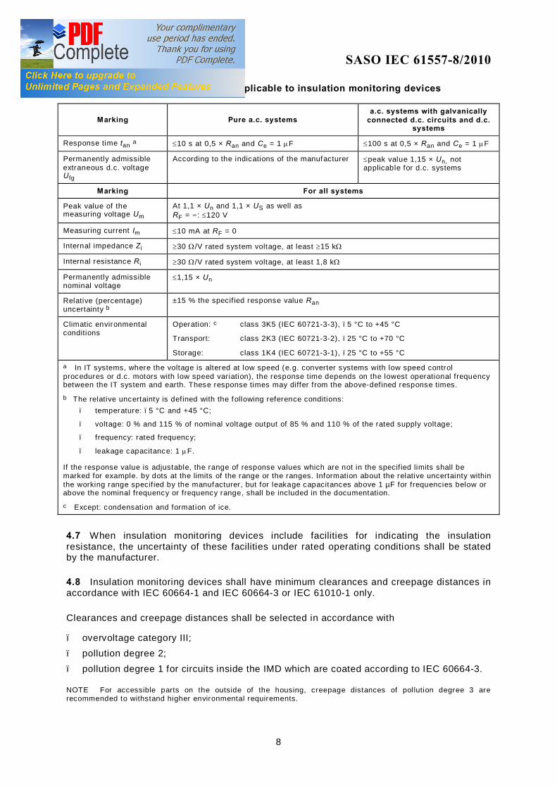
Table 1 – Requirements applicable to insulation monitoring devices
Marking Pure a.c. systems a.c. systems with galvanically
connected d.c. circuits and d.c. systems
Response time tan a ≤10 s at 0,5 × Ran and Ce = 1 µF ≤100 s at 0,5 × Ran and Ce = 1 µF
Permanently admissible extraneous d.c. voltage U fg
According to the indications of the manufacturer ≤peak value 1,15 × Un, not applicable for d.c. systems
Marking For all systems
Peak value of the measuring voltage Um
At 1,1 × Un and 1,1 × US as well as RF = ∞: ≤120 V
Measuring current Im ≤10 mA at RF = 0
Internal impedance Z i ≥30 Ω/V rated system voltage, at least ≥15 kΩ
Internal resistance R i ≥30 Ω/V rated system voltage, at least 1,8 kΩ
Permanently admissible nominal voltage
≤1,15 × Un
Relative (percentage) uncertainty b
±15 % the specif ied response value Ran
Climatic environmental conditions
Operation: c class 3K5 (IEC 60721-3-3), –5 °C to +45 °C
Transport: class 2K3 (IEC 60721-3-2), –25 °C to +70 °C
Storage: class 1K4 (IEC 60721-3-1), –25 °C to +55 °C
a In IT systems, where the voltage is altered at low speed (e.g. converter systems with low speed control procedures or d.c. motors with low speed var iation), the response time depends on the lowest operational frequency between the IT system and earth. These response times may differ from the above-defined response times.
b The relative uncertainty is def ined with the following reference conditions: – temperature: –5 °C and +45 °C;
– voltage: 0 % and 115 % of nominal voltage output of 85 % and 110 % of the rated supply voltage;
– f requency: rated frequency;
– leakage capacitance: 1 µF.
If the response value is adjustable, the range of response values which are not in the specif ied limits shall be marked for example. by dots at the limits of the range or the ranges. Information about the relative uncertainty within the working range specif ied by the manufacturer, but for leakage capacitances above 1 µF for frequencies below or above the nominal frequency or frequency range, shall be included in the documentation.
c Except: condensation and formation of ice.
4.7 When insulation monitoring devices include facilities for indicating the insulation resistance, the uncertainty of these facilities under rated operating conditions shall be stated by the manufacturer.
4.8 Insulation monitoring devices shall have minimum clearances and creepage distances in accordance with IEC 60664-1 and IEC 60664-3 or IEC 61010-1 only.
Clearances and creepage distances shall be selected in accordance with
– overvoltage category III; – pollution degree 2; – pollution degree 1 for circuits inside the IMD which are coated according to IEC 60664-3.
NOTE For accessible parts on the outside of the housing, creepage distances of pollution degree 3 are recommended to withstand higher environmental requirements.

SAUDI STANDARD SASO IEC 61557-8/2010
9
4.9 Where different voltages are used by an insulation monitoring device (e.g. US, Un), clearances and creepages shall be designed for the highest voltage.
4.10 A division into circuits with different nominal insulation voltages is permissible in device combinations (e.g. for IT systems with nominal voltages higher than 1 000 V a.c. and 1 500 V d.c.) when the electrical connection is made via resistive, capacitive or inductive voltage dividers and if, in the case of a fault, the occurrence of inadmissibly high touch voltages or inadmissibly high currents to earth are prevented by circuit design features. Such circuit design features (see IEC 61140) can be, for example, additionally provided in the form of reliable voltage dividers or a duplication of the resistors (safety impedance) in the voltage divider.
4.11 Insulation monitoring devices shall comply with the requirements for electromagnetic compatibility (EMC) in accordance with IEC 61326-2-4.
4.12 Additional requirements for insulation monitoring devices are listed in Table 1.
5 Marking and operating instructions
5.1 Marking
In addition to the marking in accordance with IEC 61557-1, the following information shall be provided on the insulation monitoring device.
5.1.1 Type of device as well as mark of origin or name of the manufacturer.
5.1.2 IT system to be monitored (if the IMD is designed for a specific type of IT system).
5.1.3 Wiring diagram or number of the wiring diagram or number of the operating instructions.
5.1.4 Nominal system voltage Un or range of the nominal voltage.
5.1.5 Nominal value of the rated supply voltage US or working range of the rated supply voltage.
5.1.6 Nominal frequency of the rated supply voltage US or working range of frequencies for the rated supply voltage.
5.1.7 Specified response value Ran or minimum and maximum response value Ran and, if applicable, the range of specified response values where the relative (percentage) uncertainty is higher than that listed in Table 1.
5.1.8 Mandatory on the outside and, if necessary, inside the device: serial number, year of manufacture or type designation.
The data given in 5.1.1 shall be indelibly marked on the insulation monitoring device in such a manner that they remain legible after installation of the device.

SAUDI STANDARD SASO IEC 61557-8/2010
10
5.2 Operating instructions
The operating instructions shall state the following in addition to the statements given in IEC 61557-1.
5.2.1 Internal impedance Z i of the measuring circuit as a function of the nominal frequency.
5.2.2 Peak value of the measuring voltage Um in accordance with Table 1 when fed with the nominal value of the rated supply voltage US.
5.2.3 Maximum value of the measuring current Im in accordance with Table 1 when the terminals are short-circuited.
5.2.4 Technical data of the interface for the connection of an external warning device including rated voltage and current, rated insulation voltage and explanation of the interface function. For contact circuits, data shall reference to IEC 61810-2 or IEC 60947-5-1 and IEC 60947-5-4.
5.2.5 Information that insulation monitoring devices shall not be connected in parallel (e.g. when systems are coupled).
5.2.6 Wiring diagram when this is not marked on the devices in accordance with 5.1.3.
5.2.7 Information relating to the effect of the system leakage capacitances Ce, and their permissible maximum value.
5.2.8 Extraneous d.c. voltage (Ufg) of any polarity that can be applied continuously to the insulation monitoring device without damaging it.
5.2.9 Test voltage according to 4.9 and conformity to the relevant EMC standards.
5.2.10 Electrical data for the contact circuits according to 5.2.4.
5.2.11 Internal resistance Ri of the measuring circuit.
6 Tests
The following tests in addition to those required according to IEC 61557-1 shall be executed.
6.1 Type tests
Type tests shall be executed in accordance with 6.1.1 to 6.1.7.
6.1.1 Response values
Response values shall be tested at the lowest and at the highest value of the specified nominal voltage Un and of the rated supply voltage US.
For this test insulation resistance shall be simulated as follows:
– single pole (from one phase of Un); – symmetrically (same resistor from all phases of Un).

SAUDI STANDARD SASO IEC 61557-8/2010
11
The measuring devices for the tests shall be able to accommodate slow, continuous or fine step changes in the simulated insulation resistance as well as an additional parallel connection of leakage capacitances. Capacitors with an insulation resistance of at least one hundred times the specified response value and a tolerance limit of 10 % maximum shall be used for simulating system leakage capacitances. During testing, the test resistance shall be reduced slowly, starting from high values, while observing the operation of the insulation monitoring device. The insulation resistances and intrinsic leakage capacitances presented by the test circuit shall be taken into account when determining the response value.
When the insulation monitoring device is provided with a continuously variable specified response value, or digital setting without mechanical switches, the compliance with the conditions listed in Table 1 shall be checked at a minimum of five points of the setting range. This check shall be executed at the end points as well as at approximately evenly distributed points in the setting range. This also applies to setting facilities without a switch.
If the specified response value can be set by means of a mechanical switch, each step shall be tested. The initial test shall be executed without any system leakage capacitances in circuit whilst the test resistance is reduced so slowly that the steady-state response value can be found.
Detailed statements shall be provided by the manufacturer. If the measuring method is affected by the magnitude of the system leakage capacitance Ce, a check shall be carried out by means of an insertion of capacitors, in steps, to determine whether the limits listed in Table 1 are met over the range of capacitance stated by the manufacturer. The relative percentage uncertainty shall be determined.
6.1.2 Response time
With a leakage capacitance Ce of 1 µF and at the nominal system voltage, the insulation resistance shall be suddenly reduced from nearly infinity to 50 % of the minimum response value Ran, and the delay to the operation of the output circuit shall be measured.
6.1.3 Peak value of the measuring voltage Um
A peak voltage measurement shall be used to check whether the requirements given in Table 1 are met and whether the statement under 5.2.2 is applicable. The internal resistance of the voltage measuring instrument shall be at least 20 times the internal d.c. resistance R i of the measuring circuit.
6.1.4 Internal resistance and impedance
The following tests shall be used to check whether the requirements given in Table 1 are met. These tests shall be executed with or without rated supply voltage US and an appropriate measuring voltage shall be applied between the interconnected system terminals and the earth terminal. The uncertainty limit of the measuring devices shall not exceed 5 % under reference conditions.
6.1.4.1 Internal impedance Zi
For determining the internal impedance Z i in accordance with Table 1, the voltage source shall be identical to the nominal system voltage Un, the frequency shall be identical to the nominal system frequency, the distortion factor shall be below 5 % the internal resistance shall be below 10 Ω.

SAUDI STANDARD SASO IEC 61557-8/2010
12
The internal impedance is calculated from the peak-to-peak value Ipp of the resulting current by using the following equation:
Z UIi
n
pp=
× ×2 2
6.1.4.2 Internal d.c. resistance Ri
For determining the internal d.c. resistance R i in accordance with Table 1, the d.c. voltage shall have a magnitude in the order of the nominal system voltage Un, but not exceed the permissible maximum extraneous d.c. voltage Ufg. The internal d.c. resistance R i is calculated from the resulting current I by using the following equation:
R in
n fg= ≤UI
U U( )
6.1.5 Facilities for indicating the insulation resistance
When insulation monitoring devices are fitted with facilities for indicating the insulation resistance, a test shall be carried out to check whether the uncertainty limits stated by the manufacturer in accordance with 4.7 are met.
6.1.6 Dielectric strength tests
Insulation monitoring devices shall be tested in accordance with IEC 61010-1.
6.1.7 Electromagnetic compatibility (EMC)
The electromagnetic compatibility test shall be executed in accordance with 4.11.
6.2 Routine tests
Routine tests shall be executed on each insulation monitoring device.
NOTE If by technical fai lure analyses and / or statistical analyses during the series production, a low failure rate can be verif ied, routine tests can be limited to reduce sampling tests. All routine tests should be carried out either during the manufacturing process or at the end.
6.2.1 Response values
Routine tests of the relative (percentage) uncertainty of the response values shall be executed in accordance with 6.1.1. In this test, the following conditions apply:
– room temperature (23 °C ± 3 °C); – at 1,0 times Un and 1,0 times US or the highest rated Un or US for a device with several
rated voltages;
– with Ce = 1 µF.
In this test, the limits shall be reduced to such a degree that the conditions in Table 1 are met. When the insulation monitoring device is provided with a continuously variable specified response value, then the operation shall be checked at a minimum of three points in the setting range. In doing so, the starting point and the end point as well as one point in the centre of the setting range shall be checked. When the specified response value is chosen in steps by means of a mechanical switch, then each step shall be checked.

SAUDI STANDARD SASO IEC 61557-8/2010
13
6.2.2 Effectiveness of the test devices
The internal test button and the external test button, if provided, shall be checked for correct operation and compliance with the requirements given in 4.2.
6.2.3 Facility for indicating the insulation resistance
When, in accordance with 4.7, the insulation monitoring device comprises facilities for indicating the insulation resistance, then a check shall be carried out to determine if the uncertainty limits stated by the manufacturer are met.
6.2.4 Dielectric strength test
Insulation monitoring devices shall be tested in accordance with Annex F of IEC 61010-1.
6.2.5 Marking and operating instructions
Checking by visual inspection.
6.2.6 The compliance with the tests in this clause shall be recorded.

SAUDI STANDARD SASO IEC 61557-8/2010
14
Annex A (normative)
Medical insulation monitoring devices (IMDs)
A.1 Scope and object
This annex specifies the requirements for insulation monitoring devices which permanently monitor the insulation resistance to earth of unearthed IT a.c. systems in group 2 medical locations according to clause 710.413.1.5 of IEC 60364-7-710.
NOTE The information and requirements specif ied here replace or supplement the corresponding clauses and subclauses of the main text of this standard, as indicated.
A.2 Definitions
For the purposes of this annex, the definitions given in Clause 3 and the following definitions apply.
A.2.1 group 2 medical locations medical locations where applied parts are intended to be used in applications such as intracardiac procedures, operating theatres and vital treatment where discontinuity (failure) of the supply can cause danger to life
NOTE An intracardiac procedure is a procedure whereby an electrical conductor is placed within the cardiac zone of a patient or is likely to come into contact with the heart, such conductor being accessible outside the patient's body. In this context, an electrical conductor includes insulated wires, such as cardiac pacing electrodes or intracardiac ECG-electrodes, or insulated tubes f illed with conducting f luids.
[IEC 60364-7-710, definition 710.3.7, modified)
A.2.2 medical insulation monitoring device (medical IMD) specific insulation monitoring devices (IMDs) dedicated to monitor IT systems of group 2 medical location. These devices shall comply with this annex.
A.3 Requirements
The following requirements or modifications as well as those given in this part of IEC 61557 shall apply.
A.3.1 EMC
IEC 61326-2-4 is applicable.
Radiated and conducted emissions shall be tested according to Table A.2.

SAUDI STANDARD SASO IEC 61557-8/2010
15
A.3.2 Internal impedance (Zi)
The a.c. internal impedance shall be at least 100 kΩ (see Table A.1).
A.3.3 Measuring voltage (Um)
The measuring voltage shall not be greater than 25 V peak.
A.3.4 Measuring current (Im)
The measuring current shall not be greater than 1 mA peak (see Table A.1), even under fault conditions.
If the IT system includes galvanically connected d.c. circuits, the device shall be able to detect insulation resistances within the entire IT system, as specified in this standard, even with insulation faults on the d.c. side.
NOTE Measuring current is designated as injected current in IEC 60364-7-710.
A.3.5 Warning indication
The warning indication shall take place at the latest when the insulation resistance has decreased to 50 kΩ. A test device shall be provided according to 4.2 of this standard.
NOTE When the response value is adjustable, all this response value should be ≥ 50 KΩ.
For each medical IT system, an acoustic and visual alarm system (internal or external of the Medical IMD), incorporating the following components, shall be arranged at a suitable place, so that it can be permanently monitored (audible and visual signals) by the medical staff:
– a green signal lamp to indicate normal operation; – a yellow signal lamp which lights when the warning indication of the insulation monitoring
device takes place. It shall not be possible for this light to be cancelled or disconnected; – an audible alarm which sounds, when the minimum value set for the insulation resistance
is reached. This audible alarm may have provisions to be silenced under alarm conditions; – the yellow signal and the audible alarm shall be cancelled on removal of the fault and
when normal condition is restored.
NOTE It is also recommended to have an indication if the earth connection or the connection to the system to be monitored is lost.
A.3.6 Response times
The response time shall be below 5 s for an insulation resistance of 25 kΩ (50 % of 50 kΩ), if suddenly applied.
The alarm off-time clearing the fault shall be below 5 s for an insulation resistance suddenly rising from 25 kΩ to 10 MΩ.
Response and alarm-off times shall be adhered to, for a system leakage capacitance up to 0,5 µF.
If the leakage capacitance in the medical IT system is higher than 0,5 µF, the response time can be longer than 5 s.

SAUDI STANDARD SASO IEC 61557-8/2010
16
For medical insulation monitoring devices (IMDs), which perform an automatic periodic self test for the purpose of functional safety, the response time can be extended during self-testing.
NOTE If the insulation monitoring device (IMD) includes means for the indication of loss of the connection to earth or to the system to be monitored, the response time for this function can be longer, as for insulation monitoring according to Table 1.
The response time for the indication of loss of the connection should be indicated in the operating instructions.
A.4 Marking and operating instructions
Clause 5 of this standard applies.
NOTE If the medical IMD is designed to fulf il requirements of Annex B, additional marking and operating instructions should be provided according to Clause B.3 of this standard.
A.5 Tests
The following tests in addition to those required according to this part of IEC 61557 shall be executed. The tests of Clause 6 shall be executed with the values of Table A.1.
A.5.1 Type tests
Subclause 6.1.3 does not apply.
A.5.1.1 Maximum value of the measuring voltage Um and of the measuring current Im
A measurement shall be used to check whether the requirements given in A.3.3 and A.3.4 are met. The internal resistance of the instrument to measure Um shall be at least 20 times the internal d.c. resistance R i of the medical insulation monitoring device (IMD).
NOTE If the device includes means for the indication if the earth connection and/or the connection to the system to be monitored is lost, the following tests should be performed:
An alarm should take place, if the FE connection or the connection to the system or all connections together are disconnected.
Table A.1 – Additional requirements applicable to medical insulation monitoring devices (IMDs)
Additional requirements
Response time tan
a ≤5 s at 25 KΩ and Ce = 0,5 µF
Peak value of the measuring voltage Um At 1,1 × Un and 1,1 × Us and at RF = ∞ : ≤25V
Measuring current Im ≤1 mA at RF = 0 Ω
Internal impedance Z i ≥100 kΩ at 50 Hz – 60 Hz
Internal resistance R i ≥Um / 1 mA
Permanently admissible rated voltage Value of Table 1 applies
Relative (percentage) uncertainty Value of Table 1 applies
Climatic environmental conditions Values of Table 1 apply
a The response time shall be kept in pure a.c. systems as well as in a.c. systems with galvanically connected d.c. circuits.

SAUDI STANDARD SASO IEC 61557-8/2010
17
Table A.2 – Emission test for medical insulation monitoring devices (IMDs)
Test No. Access Test Specification Class Comment Basic Standard
1 Complete device
Radiated disturbance emission
30 MHz to 230 MHz 230 MHz to 1 000 MHz
B At rated voltage
CISPR 11
2
Supply connections and main connections
Conducted disturbance emission
150 kHz to 30 MHz B At rated voltage
CISPR 11

SAUDI STANDARD SASO IEC 61557-8/2010
18
Annex B (informative)
Monitoring of overload and high temperature
B.1 Scope and object
This annex specifies the requirements for devices designed for monitoring overload and temperature of the medical IT transformer according to 710.413.1.5 of IEC 60364-7-710.
These functions can be incorporated in medical insulation monitoring devices (IMDs) as an option.
NOTE The information and requirements specif ied here replace or supplement the corresponding clauses and subclauses of the main text of this standard, as indicated.
B.2 Requirements
B.2.1 Monitoring of overload and high temperature
The following requirements shall apply:
B.2.1.1 The warning indication shall take place at the latest when the load current exceeds the rated output current of the transformer.
NOTE It is recommended that the response value for load current monitoring is adjustable and the trip value can be set below the rated output current of the transformer, to take into account individual safety margins.
B.2.1.2 The r.m.s. value of the load current shall be measured at least with a crest factor of 2.
B.2.1.3 The warning indication shall take place, if the temperature sensitive device (bimetal, PTC or similar) in the medical IT transformer signals overtemperature.
NOTE It is also recommended to have an indication if the connection to the load current sensor is open or short circuited and if the connection to the overtemperature sensor is open.
B.3 Marking and operating instructions
B.3.1 Marking
In addition to the marking in accordance with IEC 61557-1, the following information shall be provided on the device.
B.3.1.1 Specified response value or range of specified response values for load current monitoring.
B.3.1.2 Type of external load current sensor; relative percentage uncertainty of load current measurement.
B.3.1.3 Type of temperature-sensitive device according to IEC 60691 in the medical IT transformer which can be connected.

SAUDI STANDARD SASO IEC 61557-8/2010
19
B.3.1.4 Response time for overload and overtemperature alarm as well as for connection alarm for these functions.
B.4 Tests
The following tests in addition to those required according to IEC 61557-1 shall be executed.
B.4.1 Overload and overtemperature monitoring
The trip value for overcurrent indication, indicated by the manufacturer, shall be tested by simulation of the respective load current.
The overtemperature alarm shall be tested by the simulation of overtemperature through the respective temperature-sensitive device (bimetal, PTC or similar).

SAUDI STANDARD SASO IEC 61557-8/2010
20
Bibliography
IEC 60364-4-41, Low-voltage electrical installations – Part 4-41: Protection for safety – Protection against electric shock
IEC 61140, Protection against electric shock – Common aspects for installation and equipment
___________