saso oiml r 41
TRANSCRIPT

KINGDOM OF SAUDI ARABIA SAUDI ARABIAN STANDARDS ORGANIZATION
SASO
SASO OIML R 41 :2006
Standard burettes for verification officers

SAUDI STANDARD SASO OIML R 41:2006
1
FOREWORD
The Saudi Arabian Standards Organization (SASO) has adopted the International standard No. OIML R 41/1981 “Standard burettes for verification officers” issued by the OIML. The text of this international standard has been translated into Arabic so as to be approved as a Saudi standard without introducing any technical modification.

SAUDI STANDARD SASO OIML R 41:2006
2
STANDARD BURETTES
for VERIFICATION OFFICERS
1. Genera l. 1.1. This Recommendation deals with standard burettes used by verification officers :
a) for testing capacity measures used by the public, for the measurement of volume of liquids
b) or as auxiliary standards of capacity.
1.2. The standard burettes for verification officers covered by this Recommendation, are intended to replace existing burettes taken out of service, or when new sets of burettes have to be acquired.
2. Definitions.
2.1. Capacity
The capacity corresponding to any scale mark is equal to the volume of water, at the reference temperature, delivered by the burette at this temperature when it is emptied from the zero mark to this scale mark, the outflow being unrestricted until the meniscus is set on this scale mark, no period being allowed for drainage of liquid adhering to the walls before making the final setting. Note : The meniscus formed by the water in the burette, must be so adjusted that the horizontal plane passing
through the upper edge of the scale mark, is tangential to the lowest point of the meniscus when viewed in this plane.
2.2. Nominal capacity
The nominal capacity is the maximum numbered value of the scale of volumes shown on the burette.
2.3. Delivery time
Is the time required for the free descent of the water meniscus, from the zero mark to the lowest numbered scale mark, with the stopcock fully open and with no restriction of flow.
3. Nominal capacities. 3.1. Unit
The unit of volume is the cubic centimetre (cm3).
Note : the term « millilitre » (ml) may also be used as a special name for the cubic centimetre.
3.2. Values
Burettes must have one of the following nominal capacities :

SAUDI STANDARD SASO OIML R 41:2006
3
10 cm3, 25 cm3, 50 cm3 or 100 cm3. Note (a) : For special purposes, burettes of different nominal capacities may be used, for example 5 or 20 cm3, provided that they comply with the other provisions of this Recommendation, where applicable.
Note (b) : The choice of nominal capacities may be made in accordance with national legal requirements.
3.3. Reference temperature
The reference temperature, i.e. the temperature at which the burette is intended to deliver a volume equivalent to its nominal capacity, must be 20 °C.
Note : When, in certain tropical countries it is necessary to use burettes at temperatures exceeding 20 °C , and if these countries do not wish to adopt the reference temperature of 20 °C, it is recommended that a temperature of 27 °C be adopted.
4. Material.
4.1. The burettes must be constructed of clear glass, transparent, well annealed and having suitable thermal and chemical properties. The glass must be free from visible defects, which might influence the appearance or use of the burette, in particular in the vicinity of the graduated scale.
4.2. Keys of stopcocks may be made of glass, or of any other suitable material.
5. Construction, shape and dimensions.
5.1. The burettes must be of sufficiently robust construction to withstand normal use.
5.2. The walls must not have any substantial variations in thickness.
5.3. The burettes must be cylindrical in shape.
The top edge must be smoothly finished, and be square to the axis of the burette.
5.4. The lower part must terminate in a stopcock and a delivery jet, both being an integral part of the burette.
5.5. Glass stopcocks must be ground, to ensure easy turning, and to prevent leakage greater than that specified in point 6.
The ground part should, preferably, have a taper of 1/10.
Suitable devices for holding the handle of the stopcock are permitted, if necessary. 5.6. The diameter of the bore of the stopcock must be about 2 mm. The dimensions of
stopcocks must comply with national regulations (*).
5.7. The tip should taper evenly, but without any sudden constriction at the orifice.
It should, preferably, be ground smooth, square to the axis of the burette, and be slightly bevelled on the outside.
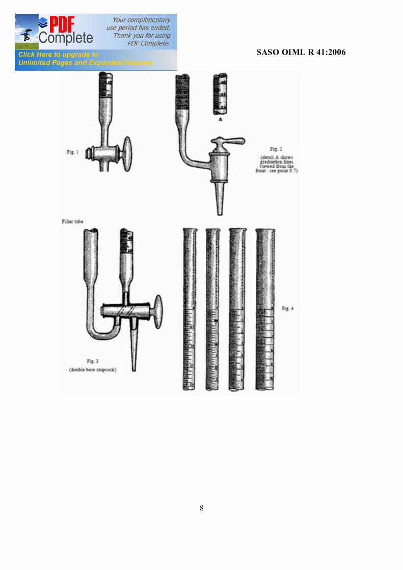
(*)There are burettes with a filler tube in addition to the graduated tube, the tubes being shut off by a double-bore stopcock, the bores having a diameter of approximately 2 mm (see fig. 3). This type of burette may be used as a standard burette, provided that it satisfies the conditions of this Recommendation, and in addition, the special requirements concerning the water-tightness of the filler tube (see appendix, point B.2.2.(.

SAUDI STANDARD SASO OIML R 41:2006
4
It may also be lightly fire glazed, provided that the requirements of the first sentence of this paragraph are met.
5.8. The tip must be manufactured from thick-wall capillary tube.
At the joining with the stopcock, there must be no cavity liable to retain air bubbles.
5.9. The tip must form an integral part of the burette, either by being joined to the stopcock plug, or
by forming part of the stopcock key (figures 1 and 2).
5.10. Dimensions of the burette must be as shown in Table I (page 11).
6. Leakage test. 6.1. The water-tightness of stopcocks must be tested, in accordance with the method
specified in appendix B.
7. Delivery time. 7.1. The delivery time is determined with the stopcock fully open, and the tip not in
contact with the wall of the receiving vessel.
The delivery time determined in this way must be within the limits indicated below:
Delivery time
. Min. Max s s
Nominal capacity cm3
100 170 150 150
70 120 105 100
10 25 50 100
7.2. The delivery time must be marked on the burette.
The delivery time observed during metrological testing, and the delivery time marked on the burette, must be within the limits specified in the Table in point 7.1., and must not differ from each other by more than 10 % of the marked value.
8. Scale (see fig. 4, page 1 0) .
8.1. The scale must be regular ; the lines must be distinct, permanent, and of uniform thickness, not exceeding 0.3 mm.
8.2. The lines must be at right angles to the longitudinal axis of the graduated part of the burettes.
8.3. The values of the scale divisions are specified in Table II. The length of the scale division must be such that total scale length is within the limits specified in Table I.
8.4. The lowest numbered line must correspond to the nominal capacity, but unnumbered lines may, if desired, be continued below the line corresponding to the nominal capacity, for a length on the burette corresponding to the volumes given below :

SAUDI STANDARD SASO OIML R 41:2006
5
Value of continuation Cm3
Nominal capacity Cm3
0.5 1 2 5
10 25 50
100
8.5. The lengths of the graduation lines must be varied to be clearly distinguishable, in
accordance with the following :
8.5.1. The long lines must extend completely around the burette, or have a length corresponding to approximately 9/10 of the circumference, the interruption in each line being centered on the right lateral generatrix when the burette is viewed from the front.
8.5.2. The length of the medium lines must be approximatly 2/3 of the circumference of the burette.
8.5.3. The length of the short lines must be equal to, or slightly greater than one half of the
circumference.
8.5.4. The medium lines must extend symmetrically, on either side, beyond the ends of the short lines.
٨.6. The distribution of the lines of different lengths must meet the following provisions :
8.6.1. Burettes with a nominal capacity of 10 and 25 cm3 :
a) the zero line and every tenth line must be a long line,
b) there must be four medium lines, equally spaced between two consecutive long lines,
c) there must be one short line between two consecutive medium lines, and between, consecutive medium and long lines.
8.6.2. Burettes with a nominal of 50 cm3 :
a) the zero line and every tenth line must be a long line,
b) there must be one medium line midway between two consecutive long lines,
c) there must be four short lines, equally spaced between consecutive long and medium lines.
8.6.3. Burettes with a nominal capacity of 100 cm 3:
a) the zero line and every fifth line must be a long line ;
b) there must be four short lines, equally spaced between two consecutive long lines.
8.7. When the burette is viewed from the front, in its normal position of use, namely :

SAUDI STANDARD SASO OIML R 41:2006
6
— with the stopcock handle on the right of the operator (fig. 1),
— or in the case of the type of burette shown in fig. 2, with the lower curved part pointing towards the operator, the beginning of each short line must lie on an imaginary vertical line, down the centre of the front part of the burette, with the lines extending to the left.
8.8. The lines must be numbered from the top downwards, starting at zero, at the intervals as specified in Table II.
8.9. The numbers must be placed immediately above the long lines, to which they refer and to the right of the adjacent shorter lines.
8.10. Lines and numbers must be clearly legible and indelible.
9. Maximum permissible errors on initial and subsequent verification. 9.1. The maximum permissible errors on the nominal capacity of a burette, are as follows
:
Maximum permissible error
cm3 Nominal capacity
cm3 ± 0.02 ± 0.03 ± 0.05
± 0.1
10 25 50
100
9.2. The maximum permissible error on the capacity corresponding to any scale mark, is
equal to the maximum permissible error on the nominal capacity of the burette.
The maximum permissible error on the capacity between any two scale marks, is also equal to the maximum permissible error on the nominal capacity of the burette.
9.3. A recommended method for the verification of burettes is given in the appendix A.
9.4. The burette must be verified at five scale marks, evenly spaced between the nominal capacity andzero marks.
10. inscription.
10.1. The following inscriptions must be included on the un-graduated part of each burette :
a) one or more appropriate letters, to indicate that the burette is a « standard burette for verification
officers »,
b) nominal capacity in Arabic numerals, followed by the symbol cm3 (or ml),
c) the conventional marking « Ex 20 °C » or « Ex 27 °C », to indicate that the burette has been adjusted to « deliver » liquid at the reference temperature of 20 °C or 27 °C, as appropriate,

SAUDI STANDARD SASO OIML R 41:2006
7
d) delivery time in seconds,
e) manufacturer's name or trademark,
f) the serial number of the burette, marked on the body and stopcock handle.
10.2. All inscriptions must be clearly legible and indelible, under normal conditions of use of the burettes.
1 1 . Stamping of burettes. 11.1. Each burette must :
— either be marked in a suitable manner after each verification, in a place which does not obstruct observation of the meniscus,
— or be given a certificate of verification, in which case the certificate must show the serial number of the burette.
12. Frequency of verification. 12.1. Burettes must be verified at intervals of time as prescribed by national regulations.
Note : It is recommended that this interval be ten years.
13. Boxes.
13.1. The burettes may be housed in dust-proof boxes, made of suitable materials, and lined, if necessary, with velvet, chamois leather, soft plastics or any other suitable material.
Note : Burettes obtained as replacements for burettes in current use, may be placed in existing boxes.
13.2. The burettes must be placed in their boxes, in such a way as to avoid any movement, dislodgement or damage.
14. Inscriptions on the box.
14.1. A descriptive plate bearing the following information must be affixed to each box containing standard burettes :
a) national identification mark,
b) manufacturer's name or trademark,
c) identification number,
d) range of standard burettes contained,
and
e) designation of the burettes, for example :
« verification officers standard burettes ».
14.2. Other markings may be provided, in accordance with national regulations.
SAUDI STANDARD SASO OIML R 41:2006
8

SAUDI STANDARD SASO OIML R 41:2006
9
Overall length Max
Length of scale Nominal capacity cm3 Max Min
570 820 820 870
350 600 600 650
250 500 500 550
10 25 50 100
Distance between the zero mark and the top of the burette Min 50 Distance between the lowest scale mark and the top of the stopcock Min 50 Length of tube of uniform section below the lowest scale mark Min 20 Distance between the underside of the stopcock and the end of the tip Min 50
TABLE II Graduation
Numbering by Cm3
Scale interval Cm3
Nominal capacity Cm3
0.5 0.05 10 0.5 0.05 25 1 0.1 50 2 0.2 100

SAUDI STANDARD SASO OIML R 41:2006
10
APPENDIX A VERIFICATION OF STANDARD BURETTES FOR VERIFICATION OFFICERS A.1. Test liquid.
A.1.1. Water : distilled or deionized of high purity, in accordance with the following requirements when tested immediately before use :
It must be free from dissolved gases, and heavy metals, in particular copper, as shown by the dithiozone test ; the specific conductivity must not exceed 1 × 10 – 4 S ⊕ m – 1 at 20 °C, and it must be neutral to methyl red.
A.2. Instruments. A.2.1. Scales : of suitable maximum capacity, having an accuracy at least equal to that of
nonautomatic weighing machines of the high accuracy class (or possibly special accuracy class).
A.2.2. Weighing flask : of appropriate capacity, with glass stopper.
A.2.3. Thermometer : with appropriate measuring range, suitable for the measurement of temperature with an error not exceeding ± 0.1 °C.
A.3. Method.
A.3.1.
— clean the burette,
— place in a vertical position,
— allow the temperature of burette and distilled water used for verification to equalize,
— note the water temperature,
— fill the burette to a level a few millimetres above the zero line.
A.3.2.
— remove using blotting paper, any drops of water adhering to the outside of the tip,
— allow the water to flow out freely, and set the meniscus on the zero mark (see note to point 2.1.),
— remove any excess water from the tip, by bringing the tip into contact with the wet side of a container,
— ensure that the internal walls of the burette above water level are dry, and that the water contains no bubbles or foam.
A.3.3.
— weigh a clean, dry and empty flask, including its stopper,

SAUDI STANDARD SASO OIML R 41:2006
11
— allow the water to run freely from the burette into the flask, with the tip not touching the side of the flask,
— keep the stopcock fully open during discharge, until the water level is a few millimetres above the mark being checked. At this stage reduce the flow, and set the meniscus accurately on this mark.
After this adjustement, add the drop of water adhering to the tip to the delivered volume, by bringing the inner wall of the flask into contact with the tip.
When delivery is finished, move the flask horizontally so that its wall is no longer in contact with the tip, insert the stopper, and weigh.
A.3.4. Repeat this procedure for four other scale marks, evenly spaced between the nominal capacity and zero marks.
A.4. Calculation of volume delivered. From the difference between the results of the weighing of the flask when full, and the flask when empty, and allowing for correction of the displaced air, the mass of the quantity of water delivered is obtained.
Knowing the temperature of the water in the burette, and using tables for the density of water as a function of the temperature, the volume of water delivered is determined ; from this volume, and the coefficient of cubic expansion of the glass, the conventional true capacity of the burette is determined, corresponding to the scale mark considered and at the reference temperature (20 °C or 27 °C).
The error on the capacity for any scale mark, is the difference between the capacity indicated by this mark, and the conventional true capacity corresponding to this mark, determined by the method described in points A.3.1. - A.3.4.
The error on the capacity between any two scale marks, is equal to the difference between :
— the difference between the capacities indicated by these marks, and
— the difference between the conventional true capacities for these marks determined by the method given in points A.3.1. - A.3.4.

SAUDI STANDARD SASO OIML R 41:2006
12
APPENDIX B LEAKAGE TEST
B.1. The liquid used for this test must correspond to that described in appendix A, point A.1.
B.2. Procedure.
B.2.1. The burette must be fixed in a vertical position, the stopcock completely free from traces of grease, the barrel and key moistened, and the burette, filled initially to the zero mark with water.
With the key in one or other of the « closed » positions, the leakage in 10 minutes must not exceed the volume corresponding to the scale interval.
B.2.2. In addition to this test, double bore stopcocks must not have a leakage in excess of that indicated in B.2.1., when tested in the same way, with the burette empty, and the stopcock key in the normal position for the delivery of liquid, and with the filling tube connected to a suitable graduated tube, filled with water to a level 250 mm above the zero mark of the burette.
B.2.3. To ensure sufficiently accurate determination of water-tightness, the test time will last at least 30 minutes.
B.2.4. In a warm, dry atmosphere, it is recommended that a cover be placed over the burette (or its auxiliary tube), to minimize evaporation.

SAUDI STANDARD SASO OIML R 41:2006
13
Contents
Foreword ................................................................................................................................... 1 General .................................................................................................................................. 2 Definitions................................................................................................................................ 3 Nominal capacities.................................................................................................................... 4 Material ................................................................................................................................ 5 Construction, shape and dimensions ...................................................................................... 6 Leakage test.......................................................................................................................... 7 Delivery time............................................................................................................................ 8 Scale.......................................................................................................................................... 9 Maximun permissible errors on initial and subsequent verification ......................................... 10 Inscription ................................................................................................................................ 11 Stamping of burettes ................................................................................................................ 12 Frequency of verification ..................................................................................................... Boxes..................................................................................................................................... 14 Inscriptions on the box........................................................................................................... Appendix A - Verification of standard burettes for verification officers................................ Appendix B - Leakage test....................................................................................................