satchwell product catalogue - schneider-electric.com · contents satchwell product catalogue –...
TRANSCRIPT

Satchwell Product CatalogueControllers & Building Management Systems
Issue: April 2008
SATCHWELLCAT_0408.indd 1 29/4/08 10:40:45

Satchwell Controllers & Building Management Systems As a global brand of TAC, Satchwell offers owners and users of commercial and public buildings worldwide reliable, energy-efficient and integrated solutions for controlling the heating, cooling, and ventilation systems, and related building services installed in their premises.
The Satchwell range extends from stand-alone compensators and optimisers, typically used to control heating plant in small offices and retail stores, schools, clinics, and similar buildings. At the other end of the scale, computer and web technologies are used to deliver integrated energy-saving solutions to networked building installations spanning the globe.
TAC – Global Leader in Building ITTAC is a leading provider of building automation solutions based on Open Integrated Systems for Building IT. TAC’s mission is to provide added value through building environment services for indoor climate, security and use of energy, delivered with advanced technology to end users and property owners throughout the world.
With over 80 years of experience in the HVAC, building automation and security markets, TAC employs more than 5,000 people worldwide, with partners and branches in 80 countries. TAC’s parent company, Schneider Electric, is the world leader in automation and electricity management, with over 110,000 employees worldwide and operations in 190 countries.
TAC is the fastest-growing, most innovative company in the building automation industry. We are at the forefront of growth because we deliver what our customers want, year after year, building after building.
INTRODUCTION
SATCHWEll PrOduCT CATAlOguE – INTrOduCTION2
SATCHWELLCAT_0408.indd 2 29/4/08 10:40:50
CONTENTS
SATCHWEll PrOduCT CATAlOguE – CONTENTS 3
STAND-ALONE CONTROLLERS 4
Overview 4
CSC Compensator Controllers 5
CXr AHu room reset Controller 6
CXT PId Pulse 24V Controller 7
CZu Fan Coil unit Controller 8
CZT PId 0-10Vdc Controller 9
SVT Optimiser 9
dC1100 and dC1400 Optimiser/Compensators 10
SATChwELL MICRONET 11
System Overview 11
MN350 Programmable Controllers 12
MN450 Programmable Controllers 12
MN550 Programmable Controllers 13
MN650 Programmable Controllers 14
MN50 Touch Screen display 15
MN50 lCd display 16
TAC Xenta Embedded Web Servers 17
MN50 Manager Interface 18
MN50 ArCNET router 18
MN S-link digital Temperature Sensors 19
VisiSat™2 Configuration Tool 20
remote Alarm Manager 20
MicroNet View 21
SATChwELL SIGMA 22
System Overview 22
Satchwell Sigma System Software 23
Sigma Compact Edition (CE) 24
remote Alarm Manager 24
S-632 universal Network Controller 25
S-696 universal Network Controller 26
S-796 universal Network Controller 27
S-uNC-AI Analogue Input Card 28
S-uNC-dI digital Input Card 28
S-uNC-AO Analogue Output Card 28
S-uNC-dO digital Output Card 28
S-uNC-CMd digital Output Interface Module 28
S-dNN3 distributed Network Node 29
S-IC3 Integration Controllers 30
IC-gEN Integration Software 31
upgrade Paths to Satchwell Sigma 32
IAC 420 33
IAC 600 33
Touch Screen for IAC 600 Controller 34
uniFact® Pro Terminal unit Controllers 34
AppENDIx
Sensor Translation Table 35
SATCHWELLCAT_0408.indd 3 29/4/08 10:40:50
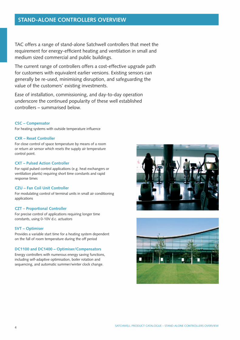
STAND-ALONE CONTROLLERS OvERvIEw
4 SATCHWEll PrOduCT CATAlOguE – STANd-AlONE CONTrOllErS OVErVIEW
CSC – CompensatorFor heating systems with outside temperature influence
CxR – Reset ControllerFor close control of space temperature by means of a room or return air sensor which resets the supply air temperature control point.
CxT – pulsed Action ControllerFor rapid pulsed control applications (e.g. heat exchangers or ventilation plants) requiring short time constants and rapid response times
CZU – Fan Coil Unit ControllerFor modulating control of terminal units in small air conditioning applications
CZT – proportional ControllerFor precise control of applications requiring longer time constants, using 0-10V d.c. actuators
SvT – OptimiserProvides a variable start time for a heating system dependent on the fall of room temperature during the off period
DC1100 and DC1400 – Optimiser/CompensatorsEnergy controllers with numerous energy saving functions, including self-adaptive optimisation, boiler rotation and sequencing, and automatic summer/winter clock change.
TAC offers a range of stand-alone Satchwell controllers that meet the requirement for energy-efficient heating and ventilation in small and medium sized commercial and public buildings.
The current range of controllers offers a cost-effective upgrade path for customers with equivalent earlier versions. Existing sensors can generally be re-used, minimising disruption, and safeguarding the value of the customers’ existing investments.
Ease of installation, commissioning, and day-to-day operation underscore the continued popularity of these well established controllers – summarised below.
SATCHWELLCAT_0408.indd 4 29/4/08 10:40:52

STAND-ALONE CONTROLLERS COMpENSATORS
FEATURES
• Easy to install and commission
• Shipped with typical default values, reducing commissioning time
• Operates a three port valve or boiler
• Max. return function for district Heating applications
• Adjustable economy function
• Night Set Back (NSB) and set-up/boost inputs
• Flow high limit feature
• user configurable day/Night plant operation
• room influence mode selection
• Cost effective upgrade of obsolete Climatronic controllers
• Compatible with previously installed Satchwell sensors
5SATCHWEll PrOduCT CATAlOguE – STANd-AlONE CONTrOllErS – COMPENSATOrS
CSC Compensator ControllersCSC Compensators are designed primarily for use in residential/commercial radiator systems to control either a three port mixing valve or a boiler. The controller senses outside temperature and varies the water flow temperature to the radiators. As the outside temperature falls, the radiator temperature is increased, and vice versa.
An optional room temperature sensor can be used to trim the water temperature based on room temperature. The CSC can average up to four room sensors.
version Output
CSC 5252 Mains or 24V output with no clock Valve or boiler, 24Vac or 230Vac
CSC 5352 Mains or 24V output with clockValve or boiler, 24vac or 230Vac, Pump triac, 24Vac, 1A maximum
data Sheet 2.021
INSTALLATION DETAILS
power supply: 230Vac 50/60Hz
power failure reserve: Settings stored in memory, 1 year battery for clock
protection class: IP 30
Switched Inputs Night Set Back (NSB): remote voltage free, make/break contacts. Normally closed. Set up (Boost): remote voltage free, make/break contacts. Normally closed.
Outputs Valve actuator or boiler output relays: 2 x single pole ON/OFF (interlocked) 230Vac, 10A resistive, 6A inductive. Pump Output: 1 x 24Vac triac, 1A (0V switched). Clock version only. Output Supply: 2 x 24Vac terminals used to power external devices up to a total of 10VA maximum.
SENSORS
Current Sensor Type Replaces
STR600 Space drT 3453
STR612 Space drT 3451
STC600 Water (Strap on) dST 0001
STp660 Water (Immersion) dWT 0001
STO600 Outside dOT 0002
STR602 remote setting rPW 4425
SATCHWELLCAT_0408.indd 5 29/4/08 10:40:52

ROOM RESET CONTROLLER
FEATURES
• Easy to install and commission
• Shipped with typical default values, reducing commissioning time
• Quick set mode allows basic settings to be easily checked and set
• Simple override switch
• Night Set Back (NSB), set-up, summer and night sensor selection switched inputs
• Optional night sensor to protect heater battery from frost damage
• up to 4 room sensors can be used for average room temperature
• remote setting input for room set value
• Cost effective upgrade of obsolete Climatronic controllers
• Compatible with previously installed Satchwell sensors
STAND-ALONE CONTROLLERS
SATCHWEll PrOduCT CATAlOguE – STANd-AlONE CONTrOllErS – rOOM rESET CONTrOllEr6
CxR AhU Room Reset ControllerThe CXr Controller is used to control room temperature by resetting the supply duct air temperature. The room sensor resets the duct supply temperature to achieve the desired room temperature. The room temperature can be sensed in the room or extract duct. The supply duct loop has a purely proportional control action with the room reset being a proportional plus integral control action.
Control Output
CxR 5805 Single, two or three stage 24V actuator control
data Sheet 2.110
INSTALLATION DETAILS
power supply: 230Vac 50/60Hz
power failure reserve: settings stored in memory, 1 year battery for clock
protection class: IP 30
Switched Inputs Night Set Back (NSB): remote voltage free, make/break contacts. Normally closed. Set up: Voltage free, make/break contacts. Normally closed. remote low limit (Summer): remote voltage free, make/break contacts. Normally closed. Night Sensor Selection: Voltage free, make/break contacts. Normally closed.
Outputs Valve Actuator Output Triacs: 2 x 24Vac triacs, 1A (0V switched and software interlocked). Output Supply: 2 x 24Vac terminals used to power the actuator up to a total of 10VA maximum.
SENSORS
Current Sensor Type Replaces
STR602 Space drT 3651
STR600 Space drT 3453
STD660 duct ddT 0001
STp660 Water (Immersion) dWT 0001
STC600 Water (Strap on) dST 0001
STR602 remote setting rPW 4425
SATCHWELLCAT_0408.indd 6 29/4/08 10:40:53
7SATCHWEll PrOduCT CATAlOguE – STANd-AlONE CONTrOllErS – PId PulSE CONTrOllErSATCHWEll PrOduCT CATAlOguE – STANd-AlONE CONTrOllErS – rOOM rESET CONTrOllEr
FEATURES
• Easy to install and commission
• Shipped with typical default values, decreasing commissioning time
• Quick set mode allows basic settings to be easily checked and set
• Simple override switch
• Operates single or two stage systems
• Night Set Back (NSB) and set-up inputs
• remote setting input for room set value
• Cost effective upgrade of obsolete Climatronic controllers
• Compatible with previously installed Satchwell sensors
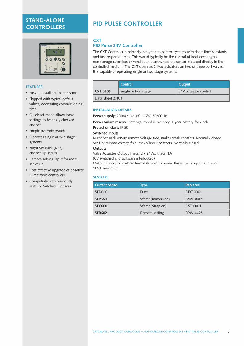
CxT pID pulse 24v ControllerThe CXT Controller is primarily designed to control systems with short time constants and fast response times. This would typically be the control of heat exchangers, non storage calorifiers or ventilation plant where the sensor is placed directly in the controlled medium. The CXT operates 24Vac actuators on two or three port valves. It is capable of operating single or two stage systems.
INSTALLATION DETAILS
power supply: 230Vac (+10%, –6%) 50/60Hz
power failure reserve: Settings stored in memory, 1 year battery for clock
protection class: IP 30
Switched Inputs Night Set Back (NSB): remote voltage free, make/break contacts. Normally closed. Set up: remote voltage free, make/break contacts. Normally closed.
Outputs Valve Actuator Output Triacs: 2 x 24Vac triacs, 1A (0V switched and software interlocked). Output Supply: 2 x 24Vac terminals used to power the actuator up to a total of 10VA maximum.
Control Output
CxT 5605 Single or two stage 24V actuator control
data Sheet 2.101
STAND-ALONE CONTROLLERS pID pULSE CONTROLLER
SENSORS
Current Sensor Type Replaces
STD660 duct ddT 0001
STp660 Water (Immersion) dWT 0001
STC600 Water (Strap on) dST 0001
STR602 remote setting rPW 4425
SATCHWELLCAT_0408.indd 7 29/4/08 10:40:53

FEATURES
• Easy to install and commission
• Three wire connection to actuators
• Optional auto changeover
• Minimal commissioning time
• Mount directly on standard dIN rail or on the terminal unit casing
CZU Fan Coil Unit ControllerThe CZu is an Electronic Modulating Controller for the control of terminal units or fan coils in air conditioning systems serving small zones of buildings such as individualoffices and hotel bedrooms.
INSTALLATION DETAILS
power supply: 24Vac (±10%) 50/60Hz
protection class: IP 20
Override Inputs: Pipe surface thermostat
Adjustments Set Value: 10 to 40°C dead Zone: 0 to 6°K, Actuator Stroke Setting: 12.5 to 75mm
Outputs: 1 or 2 stage pulsed (modulated) switched outputs. up to 7 AVu / AVuX actuators per stage
ACTUATORS
power Supply Control Action Thrust Data Sheet
AvU 2201 24Vac reversing-modulating 105N 2.201
AvUx 5202 24Vac reversing-modulating 220N 3.005
SENSORS
Current Sensor Type Replaces
STR600 Space drT 3453
STR612 Space drT 3451
STD660 duct ddT 0001
STD670 duct ddu 0001 / 1803
Control Range Output
CZU 42012-stage heating and cooling with dead zone
10 to 40°C24V actuator control
data Sheet 2.201
STAND-ALONE CONTROLLERS FAN COIL CONTROLLER
SATCHWEll PrOduCT CATAlOguE – STANd-AlONE CONTrOllErS – FAN COIl CONTrOllEr8
SATCHWELLCAT_0408.indd 8 29/4/08 10:40:54
SATCHWEll PrOduCT CATAlOguE – STANd-AlONE CONTrOllErS – FAN COIl CONTrOllEr 9
FEATURES
• Easy to install and commission
• Shipped with typical default values, decreasing commissioning time
• Quick set mode allows basic settings to be easily checked and set
• Simple override switch
• Operates single or two stage systems
• Standard 0 to 10Vdc output
• Night Set Back (NSB) and set-up inputs
• Compatible with previously installed Satchwell sensors
• remote setting input
• Cost effective upgrade of obsolete Climatronic controllers
STAND-ALONE CONTROLLERS pID 0-10vDC CONTROLLER
SATCHWEll PrOduCT CATAlOguE – STANd-AlONE CONTrOllErS – PId 0-10VdC CONTrOllEr
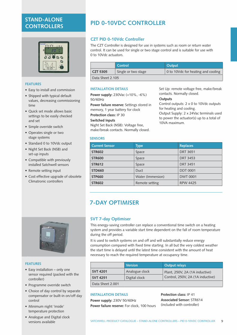
CZT pID 0-10vdc ControllerThe CZT Controller is designed for use in systems such as room or return water control. It can be used for single or two stage control and is suitable for use with 0 to 10Vdc actuators.
INSTALLATION DETAILS
power supply: 230Vac (+10%, -6%) 50/60Hz
power failure reserve: Settings stored in memory, 1 year battery for clock
protection class: IP 30
Switched Inputs Night Set Back (NSB): Voltage free, make/break contacts. Normally closed.
Set up: remote voltage free, make/break contacts. Normally closed.
Outputs Control outputs: 2 x 0 to 10Vdc outputs for heating and cooling. Output Supply: 2 x 24Vac terminals used to power the actuator(s) up to a total of 10VA maximum.
Control Output
CZT 5305 Single or two stage 0 to 10Vdc for heating and cooling
data Sheet 2.105
SENSORS
Current Sensor Type Replaces
STR602 Space drT 3651
STR600 Space drT 3453
STR612 Space drT 3451
STD660 duct ddT 0001
STp660 Water (Immersion) dWT 0001
STR602 remote setting rPW 4425
SvT 7-day OptimiserThis energy-saving controller can replace a conventional time switch on a heating system and provides a variable start time dependent on the fall of room temperature during the off period.
It is used to switch systems on and off and will substantially reduce energy consumption compared with fixed time starting. In all but the very coldest weather the start time is delayed until the latest time consistent with the amount of heat necessary to reach the required temperature at occupancy time.
FEATURES
• Easy installation – only one sensor required (packed with the controller)
• Programme override switch
• Choice of day control by separate compensator or built-in on/off day control
• Minimum night ‘inside’ temperature protection
• Analogue and digital clock versions available
version Output relays
SvT 4201 Analogue clock Plant, 250V, 2A (1A inductive)Control, 250V, 2A (1A inductive)SvT 4251 digital clock
data Sheet 2.001
INSTALLATION DETAILS
power supply: 230V 50/60Hz
power failure reserve: For clock, 100 hours
protection class: IP 41
Associated Sensor: STr614 (included with controller)
7-DAY OpTIMISER
SATCHWELLCAT_0408.indd 9 29/4/08 10:40:55
SATCHWEll PrOduCT CATAlOguE – STANd-AlONE CONTrOllErS – OPTIMISEr/COMPENSATOrS
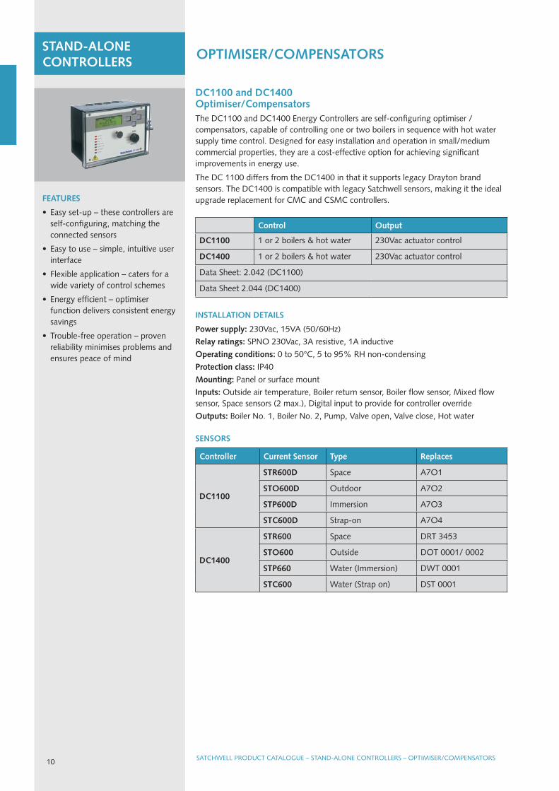
DC1100 and DC1400 Optimiser/CompensatorsThe dC1100 and dC1400 Energy Controllers are self-configuring optimiser / compensators, capable of controlling one or two boilers in sequence with hot water supply time control. designed for easy installation and operation in small/medium commercial properties, they are a cost-effective option for achieving significant improvements in energy use.
The dC 1100 differs from the dC1400 in that it supports legacy drayton brand sensors. The dC1400 is compatible with legacy Satchwell sensors, making it the ideal upgrade replacement for CMC and CSMC controllers.FEATURES
• Easy set-up – these controllers are self-configuring, matching the connected sensors
• Easy to use – simple, intuitive user interface
• Flexible application – caters for a wide variety of control schemes
• Energy efficient – optimiser function delivers consistent energy savings
• Trouble-free operation – proven reliability minimises problems and ensures peace of mind
STAND-ALONE CONTROLLERS OpTIMISER/COMpENSATORS
INSTALLATION DETAILS
power supply: 230Vac, 15VA (50/60Hz)
Relay ratings: SPNO 230Vac, 3A resistive, 1A inductive
Operating conditions: 0 to 50°C, 5 to 95% rH non-condensing
protection class: IP40
Mounting: Panel or surface mount
Inputs: Outside air temperature, Boiler return sensor, Boiler flow sensor, Mixed flow sensor, Space sensors (2 max.), digital input to provide for controller override
Outputs: Boiler No. 1, Boiler No. 2, Pump, Valve open, Valve close, Hot water
SENSORS
Controller Current Sensor Type Replaces
DC1100
STR600D Space A7O1
STO600D Outdoor A7O2
STp600D Immersion A7O3
STC600D Strap-on A7O4
DC1400
STR600 Space drT 3453
STO600 Outside dOT 0001/ 0002
STp660 Water (Immersion) dWT 0001
STC600 Water (Strap on) dST 0001
Control Output
DC1100 1 or 2 boilers & hot water 230Vac actuator control
DC1400 1 or 2 boilers & hot water 230Vac actuator control
data Sheet: 2.042 (dC1100)
data Sheet 2.044 (dC1400)
10
SATCHWELLCAT_0408.indd 10 29/4/08 10:40:57
SATChwELL MICRONET – SYSTEM OvERvIEw
MicroNet is an easy-to-use, scalable and modular building automation system, with flexible communication protocols and intuitive engineering tools. It offers unique benefits for small to medium sized buildings and complexes, providing optimum plant performance and ongoing energy savings.
SATCHWEll PrOduCT CATAlOguE – SATCHWEll MICrONET – SySTEM OVErVIEW 11
STAND-ALONE OR INTEGRATED OpERATION MicroNet fully programmable controllers can operate in stand-alone mode with a variety of user interfaces – including the highly popular MN Touch graphical touch screen – or can be integrated in local or wide area networks.
MICRONET wEB SOLUTION The addition of the TAC Xenta 555 and 731 embedded web servers offers both new and existing MicroNet users the power of the internet and optional interconnection to TAC Vista’s integrated BMS and security platform. IP Tunneling, available with VisiSat version 2.1 enables remote reprogramming and diagnostics, minimising the cost and inconvenience of returning to site.
MICRONET 50 SERIESMicroNet 50 Series, the latest and current range of MicroNet controllers, displays and routers, provides greater power, flexibility, and resilience to MicroNet system hardware, and the associated VisiSat engineering tool.
FLExIBLE ‘BUS-DU-JOUR®’ COMMUNICATIONSMicroNet gives specifiers the flexibility to choose the communications platform – NCP, ArCNET or lONWOrKS – best suited to their needs. By using the flexibility of the Xenta 555 / 731, they can even connect networks with different communication protocols – for example, when bringing together different buildings with existing installations that have previously operated in isolation from each other.
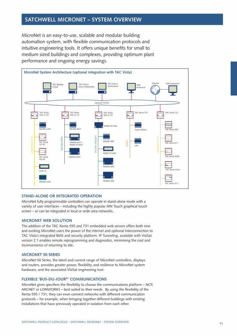
MicroNet System Architecture (optional integration with TAC vista)
Web browser(s)TAC Vista 5 Workstation
TAC Vista 5 Server/Webstation
TAC XBuilderVisiSat
InternetWebbrowser(s)
TAC Xenta555 or 731
MN350-NCP
MN550-NCP
MN650-NCP + MN50-TS-NCP
Mic
roN
et (
NC
P)
TAC Xenta555 or 731
MN350-ArC
MN550-ArC
MN50-TS-ArC
MN650-ArC
MN50-MI-ArC
Mic
roN
et (
Ar
CN
ET)
TAC Xenta 731
Power Meters
uPSMod
bus
TAC Xenta555 or 731
lON
WO
rK
S FT
T10
lON-TS
MN450-lON
MN350-lON
TAC Xenta 121-FC
TAC Xenta 102-ES
TAC Xenta 731
lON
WO
rK
S FT
T10
TAC Xenta 422A
TAC Xenta 412
TAC Xenta 411
TAC Xenta 452A
TAC Xenta 492
Ethernet TCP/IP
SATCHWELLCAT_0408.indd 11 29/4/08 10:40:58

SATChwELL MICRONET MICRONET 50 SERIES CONTROLLERS
MN450programmable ControllerThe MN450 controller is designed for rooftop, unit vent, air handling unit (AHu), and central heating and cooling applications. The controller can function in stand-alone mode or as part of a networked system using Bus-du-jour communication options. An optional real Time Clock Card can be fitted to the MN450 on an NCP network.
INSTALLATION DETAILS
power supply: 24Vac, 50/60Hz
Consumption: 10VA
protection class: IP 20
Mounting: Wall or 35mm dIN rail
Inputs: 6 universal inputs (digital, resistive, 0 to 10Vdc)
Outputs: 6 digital outputs (triac) for switching 24Vac, 3 analogue outputs (0 to 10Vdc), Current ratings for triacs:
18VA at 24Vac. Also has a 15Vdc power supply output capable of sourcing 25mA
power failure reserve: Controller EEPrOM preserves memory for 10 years under normal conditions of use. The software clock will stop during a power failure. However, if the controller has been fitted with an optional rTC card, time is maintained.
ACCESSORIES – see page 16
Controller Comms protocol Inputs/outputs
MN450-ARC Controller MN450-ArC ArCNET 6 x universal inputs
6 x digital outputs
3 x analogue outputs
MN450-LON Controller MN450-lON lON
MN450-NCp Controller MN450-NCP NCP
data Sheet 10.152
FEATURES
• lONWOrKS FTT-10, ArCNET and NCP communications options – Bus-du-jour concept
• Fully programmable using graphical objects
• Intelligent multi-loop controller – up to 7 PId control loops
• Time schedules
• Proportional, integral and derivative control actions
• 0 to 10Vdc for stepped fan control
• Averaging module for analogue inputs
• Six easily configurable Inputs: digital, analogue, 0 to 10V, resistive 0 to 10kΩ
• Supports S-link sensors
FEATURES
• lONWOrKS FTT-10, ArCNET and NCP communications options – Bus-du-jour
• Fully programmable using graphical objects
• Three built-in 230Vac relays
• 230Vac or 24Vac power supply combined with compact size
• Time schedules
• Switched outputs may be configured as stepped outputs (including plant rotation), actuator outputs or outputs for lights and fans
• Eight fully programmable Inputs: digital, analogue, 0 to 10V, resistive 0 to 10Ω
• Supports S-link sensors
MN350programmable ControllerThe MN350 controller is designed for unitary control, heating, cooling and special applications that may require built-in transformers and relays. The controller can function in stand-alone mode or as part of a networked system using Bus-du-jour communication options.
INSTALLATION DETAILS
power supply: 24Vac or 230Vac, 50/60Hz
Consumption: 12VA
protection class: IP 20
Mounting: Wall or 35mm dIN rail
Sensor Inputs: MN S-link digital sensor link
Inputs: 8 universal inputs (digital, resistive, 0 to 10Vdc)
Outputs: 4 triac outputs for switching 24Vac, 3 SPdT 230Vac relays
(line relays), Current ratings (for triac outputs): 6Va at 230Vac supply, 18VA at 24Vac supply
power failure reserve: Controller EEPrOM preserves memory for 10 years under normal conditions of use. The software clock will stop during a power failure. However, if the controller has been fitted with an optional rTC card, time is maintained.
ACCESSORIES – see page 16
Controller Comms protocol Inputs/outputs
MN350-ARC Controller MN350-ArC ArCNET 8 x universal inputs
4 x triac outputs
3 x relay outputs
MN350-LON Controller MN350-lON lON
MN350-NCp Controller MN350-NCP NCP
data Sheet 10.151
SATCHWEll PrOduCT CATAlOguE – SATCHWEll MICrONET – MICrONET 50 SErIES CONTrOllErS12
SATCHWELLCAT_0408.indd 12 29/4/08 10:40:59
13SATCHWEll PrOduCT CATAlOguE – SATCHWEll MICrONET – MICrONET 50 SErIES CONTrOllErS
SATCHWEll PrOduCT CATAlOguE – SATCHWEll MICrONET – MICrONET 50 SErIES CONTrOllErS
SATChwELL MICRONET MICRONET 50 SERIES CONTROLLERS
MN550 programmable controllerThe MN550 controller is designed for district heating, boiler plant, air handling unit (AHu), and zone heating and cooling applications.
The controller can function in stand-alone mode or as part of a networked system using Bus-du-jour communication options. An optional real Time Clock Card (rTC) can be fitted to the MN550 on an NCP network. Other options include a remote mounting Touch Screen display which allows the user to view, query and edit controller properties. An lCd display option is also available to review thecontroller parameters locally.
INSTALLATION DETAILS
power supply: 24Vac, 50/60Hz
Consumption: 12VA
protection class: IP 40
Mounting: Wall or 35mm dIN rail
Inputs: 2 digital pulse counting (10Hz) inputs, 10 universal inputs (digital, resistive, 0 to 10Vdc)
Outputs: 6 digital outputs (line relay) 5A resistive at 230Vac. 4 analogue outputs (0 to 10Vdc)
power failure reserve: Controller EEPrOM preserves memory for 10 years under normal conditions of use. The software clock will stop during a power failure. If the controller has been fitted with an optional rTC card, time is maintained.
ACCESSORIES – see also page 16
MN-DK display Wall Mounting Kit
MN-TK Trunking Mounting Kit
FEATURES
• lONWOrKS FTT-10, ArCNET and NCP communications options
• Fully programmable using graphical objects
• Intelligent multi-loop controller – up to 8 PId control loops
• Optimisation module and time schedules
• Proportional, integral and derivative control actions
• Ten fully configurable Inputs: digital, analogue 0 to 10V, resistive 0 to 10kΩ
• Six built-in line voltage relays, 230Vac 5A resistive
• Optional lCd display for interrogation of local parameters
• Supports S-link sensors
ControllerComms protocol
Inputs/outputs
MN550-ARC Controller MN550-ArC ArCNET2 x digital inputs
10 x universal inputs
6 x relay outputs
4 x analogue outputs
MN550-LON Controller MN550-lON lON
MN550-NCp Controller MN550-NCP NCP
MN550-xCOM
Controller MN550-XCOM (auxillary comms for lAN / lCd)
2 x NCP
data Sheet 10.153
SATCHWELLCAT_0408.indd 13 29/4/08 10:41:00
INSTALLATION DETAILS
power supply: 24Vac, 50/60Hz
Consumption: 15VA
protection class: IP 40
Mounting: Wall or 35mm dIN rail
Inputs: 8 digital inputs, 12 universal inputs (digital, resistive, 0 to 10Vdc)
Outputs: 8 digital outputs (triac). Current ratings 1A at 24Vac (24VA). 4 analogue outputs (0 to 10V)
power failure reserve: Controller EEPrOM preserves memory for 10 years under normal conditions of use. The software clock will stop during a power failure. If the controller has been fitted with an optional rTC card, time is maintained.
ACCESSORIES – see also page 16
MN-DK display Wall Mounting KitMN-TK Trunking Mounting Kit
FEATURES
• lONWOrKS FTT-10, ArCNET and NCP communications options
• Fully programmable using graphical objects
• Intelligent multi-loop controller – up to 8 PId control loops
• Optimisation module
• Time schedules for plant and controller switching
• Proportional, integral and derivative control actions can be individually set using controller objects
• Twelve easily configurable inputs, 8 digital inputs
• Eight triac outputs, four 0 to 10Vdc outputs
• Supports S-link sensors
SATChwELL MICRONET MICRONET 50 SERIES CONTROLLERS
MN650 programmable ControllerThe MN650 Controller is designed for rooftop, unit vent, air handling unit (AHu) and central heating and cooling applications.
The controller can function in stand-alone mode or as part of a networked system using Bus-du-jour communication options. An optional real Time Clock Card can be fitted to the MN650 on an NCP network. Other options include a touch screen and an lCd display.
ControllerComms protocol
Inputs/outputs
MN650-ARC Controller MN650-ArC ArCNET8 x digital inputs
12 x universal inputs
8 x digital outputs
4 x analogue outputs
MN650-LON Controller MN650-lON lON
MN650-NCp Controller MN650-NCP NCP
MN650-xCOM
Controller MN650-XCOM (auxillary comms for lAN / lCd)
2 x NCP
data Sheet 10.154
LIB-4-485 rS 232/rS 485 Converter to connect PC to NCP network
MN S-Link MicroNet Sensors
MNA-C ArCNET Plug-in CardMNN-COM NCP Plug-in Card for MN500 or MN620 only MN50-MI-RTR ArCNET router
MNL-C lONWOrKS Plug-in Card
MN50-MI-ARC MicroNet Manager Interface
MN50-RTC real Time Clock Card
MN-vSCORE VisiSat Configuration Tool (requires Visio 2003 software), core software (NCP, SNP & ArCNET)
MN-vSLON VisiSat lON plug-in (requires MN-VSCOrE), required for Bus-du-jour lON devices
MN50-LCD MicroNet lCd displayMN50-LCDp MicroNet lCd display (for panel mounting)MN50-TS-ARC MicroNet Touch Screen displayMN50-TS-LON MicroNet Touch Screen displayMN50-TS-NCp MicroNet Touch Screen displayMN50-TSp-ARC MicroNet Touch Screen display (for panel mounting)MN50-TSp-LON MicroNet Touch Screen display (for panel mounting)MN50-TSp-NCp MicroNet Touch Screen display (for panel mounting)
Accessories for MicroNet Controllers
SATCHWEll PrOduCT CATAlOguE – SATCHWEll MICrONET – MICrONET 50 SErIES CONTrOllErS14
SATCHWELLCAT_0408.indd 14 29/4/08 10:41:01
15SATCHWEll PrOduCT CATAlOguE – SATCHWEll MICrONET – MICrONET 50 SErIES CONTrOllErS
SATChwELL MICRONET
SATCHWEll PrOduCT CATAlOguE – SATCHWEll MICrONET – MICrONET dISPlAyS
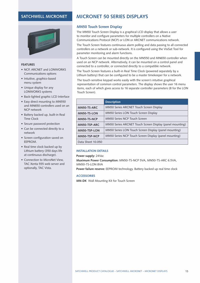
MN50 Touch Screen DisplayThe MN50 Touch Screen display is a graphical lCd display that allows a user to monitor and configure parameters for multiple controllers on a Native Communications Protocol (NCP) or lON or ArCNET communications network.
The Touch Screen features continuous alarm polling and data passing to all connected controllers on a network or sub-network. It is configured using the VisiSat Tool for parameter monitoring and alarm functions.
A Touch Screen can be mounted directly on the MN550 and MN650 controller when used on an NCP network. Alternatively, it can be mounted on a control panel and connected to a controller, or connected directly to a compatible network.
The Touch Screen features a built-in real Time Clock (powered separately by a lithium battery) that can be configured to be a master timekeeper for a network.
The touch-sensitive keypad works easily with the screen’s intuitive graphical representation of common control parameters. The display shows the user 16 menu items, each of which gives access to 16 separate controller parameters (8 for the lON Touch Screen).
FEATURES
• NCP, ArCNET and lONWOrKS Communications options
• Intuitive, graphics-based menu system
• unique display for any lONWOrKS systems
• Back-lighted graphic lCd Interface
• Easy direct mounting to MN550 and MN650 controllers used on an NCP network
• Battery backed up, built-in real Time Clock
• Secure password protection
• Can be connected directly to a network
• Screen configuration saved on EEPrOM.
• real time clock backed up by lithium battery (350 days life at continuous discharge).
• Connection to MicroNet View, TAC Xenta 555 web server and optionally, TAC Vista.
Description
MN50-TS-ARC MN50 Series ArCNET Touch Screen display
MN50-TS-LON MN50 Series lON Touch Screen display
MN50-TS-NCp MN50 Series NCP Touch Screen
MN50-TSp-ARC MN50 Series ArCNET Touch Screen display (panel mounting)
MN50-TSp-LON MN50 Series lON Touch Screen display (panel mounting)
MN50-TSp-NCp MN50 Series NCP Touch Screen display (panel mounting)
data Sheet 10.050
INSTALLATION DETAILS
power supply: 24Vac
Maximum power Consumption: MN50-TS-NCP 5VA, MN50-TS-ArC 6.5VA, MN50-TS-lON 8VA
power failure reserve: EEPrOM technology. Battery backed up real time clock
ACCESSORIES
MN-DK Wall Mounting Kit for Touch Screen
MICRONET 50 SERIES DISpLAYS
SATCHWELLCAT_0408.indd 15 29/4/08 10:41:02
16
SATChwELL MICRONET MICRONET 50 SERIES DISpLAYS
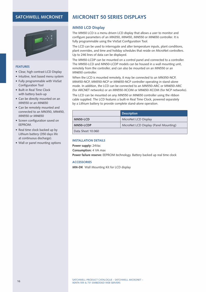
MN50 LCD DisplayThe MN50 lCd is a menu driven lCd display that allows a user to monitor and configure parameters of an MN350, MN450, MN550 or MN650 controller. It is fully programmable using the VisiSat Configuration Tool.
The lCd can be used to interrogate and alter temperature inputs, plant conditions, plant overrides, and time and holiday schedules that reside on MicroNet controllers. up to 246 lines of data can be displayed.
The MN50-lCdP can be mounted on a control panel and connected to a controller. The MN50-lCd and MN50-lCdP models can be housed in a wall mounting unit, remotely from the controller, and can also be mounted on an MN550 or an MN650 controller.
When the lCd is mounted remotely, it may be connected to an MN350-NCP, MN450-NCP, MN550-NCP or MN650-NCP controller operating in stand-alone mode. In addition, the lCd can be connected to an MN550-ArC or MN650-ArC (for ArCNET networks) or an MN550-XCOM or MN650-XCOM (for NCP networks).
The lCd can be mounted on any MN550 or MN650 controller using the ribbon cable supplied. The lCd features a built-in real Time Clock, powered separately by a lithium battery to provide complete stand-alone operation.
FEATURES
• Clear, high contrast lCd display
• Intuitive, text based menu system
• Fully programmable with VisiSat Configuration Tool
• Built-in real Time Clock with battery back-up
• Can be directly mounted on an MN550 or an MN650
• Can be remotely mounted and connected to an MN350, MN450, MN550 or MN650
• Screen configuration saved on EEPrOM.
• real time clock backed up by lithium battery (350 days life at continuous discharge).
• Wall or panel mounting options
Description
MN50-LCD MicroNet lCd display
MN50-LCDp MicroNet lCd display (Panel Mounting)
data Sheet 10.060
INSTALLATION DETAILS
power supply: 24Vac
Consumption: 4 VA max
power failure reserve: EEPrOM technology. Battery backed up real time clock
ACCESSORIES
MN-DK Wall Mounting Kit for lCd display
SATCHWEll PrOduCT CATAlOguE – SATCHWEll MICrONET – XENTA 555 & 731 EMBEddEd WEB SErVErS
SATCHWELLCAT_0408.indd 16 29/4/08 10:41:02

17
FEATURES
• Cost effective solution for new and existing installatiions
• Web access to SNP and ‘Bus-du-jour’® networks and controllers – NCP, ArCNET and lON
• Accessible from anywhere at any time through a web browser
• rich, dynamic graphics
• remote monitoring and management of alarms, events, and trend logs
• Comprehensive security features
• remote configuration capability
• VisiSat tunneling support
• No extra or specialist software required
SATChwELL MICRONET TAC xENTA EMBEDDED wEB SERvERS
The TAC Xenta 555 and 731 are multi-functional presentation systems with a built-in (embedded) web server. They offer MicroNet and Satchnet users a feature rich web solution by providing secure access to MicroNet and Satchnet networks via a web browser. All functions are easy to use and accessible via intranets and the Internet – around the clock, anywhere in the world.
As autonomous user interfaces, the Xenta 555 and 731 offer broader functionality than any other product of their kind – including complete remote configuration, trend logging, time scheduling, alarm and event monitoring. Site information is displayed dynamically through powerful web graphics pages, with continuous updating of live values in real time.
The Xenta 555 / 731 can also act as portals to TAC’s powerful Vista BMS, offering a comprehensive and integrated solution for building management and security.
The Xenta 731 provides in addition a direct control capability and enhanced network support.
SATCHWEll PrOduCT CATAlOguE – SATCHWEll MICrONET – MICrONET 50 SErIES CONTrOllErS
OThER SUppORTED pRODUCTS
MNN-30-100
MNN-44-100
MNN-50-100
MNN-62-100
MNN-lCd-100
MNN-lCdP-100
MNN-TS-100
MNN-TSP-100
MNN-MI-100
MNA-r10
MNl-TSP-100
IAC 400/420/600
IAC Touch Screen
MIu IV
uniFact
uniFact Pro
MMC 3601/4601
COMpATIBILITY
• VisiSat v.2.1 or later
• TAC XBuilder v.5.0.2 or later
• TAC Vista v.5.0.2 or later
wEB INTERFACE
Optimised for Microsoft Internet Explorer Version 6.0 or later
part Number Supported Network protocols
TAC xenta 555 0-073-0825 lON, ArCNET, NCP, SNP
TAC xenta 731 0-073-0165lON, ArCNET, NCP, SNP, I/Net, Modbus
Terminal part TAC xenta 400 0-073-0902
TAC xenta: programming Serial Kit
0-073-0920
data Sheet Xenta 555: 03-00044-01-en
data Sheet Xenta 731: 03-00046-01-en
INSTALLATION DETAILS
Supply voltage: 24 V AC ±20%, 50/60 Hz or 19–40 V dC
power consumption: max. 5 W
Transformer sizing: 5 VA
power Failure protection: Settings, e.g. configuration and web pages, are stored in the non-volatile (flash) memory and will not be lost after a power failure.
SATCHWELLCAT_0408.indd 17 29/4/08 10:41:06
SATCHWEll PrOduCT CATAlOguE – SATCHWEll MICrONET – MICrONET 50 SErIES CONTrOllErS
SATChwELL MICRONET MICRONET 50 SERIES MANAGER INTERFACE & ROUTER
INSTALLATION DETAILS
power supply: 24Vac, 50/60hz
Consumption: MN50-MI-NCP: 4.4VA
MN50-MI-ArC: 4.7VA
protection class: IP40
Mounting: wall or 35mm dIN rail
Number and Type of pC Communication ports – 2 Off rS 232
Maximum RS 232 Cable Length – 15m
power failure reserve: Non-rechargeable lithium battery
continues to run the clock and supports the unit’s rAM. Current logs and alarms in the Network Interface are preserved for up to 350 days.
ACCESSORIES
CBL-002 RS 232 D8/D9 cable from PC to MN50-MI-NCP/ArC
MNA-C ARCNET Communications card
MNR-C ARCNET router Communications card
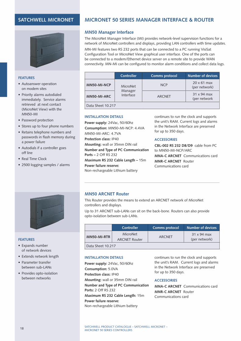
MN50 Manager InterfaceThe MicroNet Manager Interface (MI) provides network-level supervision functions for a network of MicroNet controllers and displays, providing lAN controllers with time updates.
MN-MI features two rS 232 ports that can be connected to a PC running VisiSat Configuration Tool or MicroNet View graphical user interface. One of the ports can be connected to a modem/Ethernet device server on a remote site to provide WAN connectivity. MN-MI can be configured to monitor alarm conditions and collect data logs.
Controller Comms protocol Number of devices
MN50-MI-NCp MicroNetManager Interface
NCP20 x 61 max (per network)
MN50-MI-ARC ArCNET31 x 94 max (per network
data Sheet 10.217
FEATURES
• Expands number of network devices
• Extends network length
• Parameter transfer between sub-lANs
• Provides opto-isolation between networks
INSTALLATION DETAILS
power supply: 24Vac, 50/60hz
Consumption: 5.0VA
protection class: IP40
Mounting: wall or 35mm dIN rail
Number and Type of pC Communication ports: 2 Off rS 232
Maximum RS 232 Cable Length: 15m
power failure reserve: Non-rechargeable lithium battery
continues to run the clock and supports the unit’s rAM. Current logs and alarms in the Network Interface are preserved for up to 350 days.
ACCESSORIES
MNA-C ARCNET Communications card
MNR-C ARCNET router Communications card
MN50 ARCNET RouterThis router provides the means to extend an ArCNET network of MicroNet controllers and displays.
up to 31 ArCNET sub-lANs can sit on the back-bone. routers can also provide opto-isolation between sub-lANs.
Controller Comms protocol Number of devices
MN50-MI-RTR MicroNet
ArCNET routerArCNET
31 x 94 max (per network)
data Sheet 10.217
FEATURES
• Autoanswer operation on modem sites
• Priority alarms autodialed immediately. Service alarms retrieved at next contact (MicroNet View) with the MN50-MI
• Password protection
• Stores up to four phone numbers
• retains telephone numbers and passwords in flash memory during a power failure
• Autodials if a controller goes off line
• real Time Clock
• 2500 logging samples / alarms
18
SATCHWELLCAT_0408.indd 18 29/4/08 10:41:07

19SATCHWEll PrOduCT CATAlOguE – SATCHWEll MICrONET – MICrONET rOOM SENSOrS
SATChwELL MICRONET MICRONET ROOM SENSORS
INSTALLATION DETAILS
power supply: Powered from the controller
protection class: IP 20
Ambient limits: Operating temperature 0 to 50°C, humidity 5 to 95% rh, non-condensing
MN S-Link Digital Temperature SensorsThe MicroNet MN S-link Series is a family of digital wall temperature sensors for use with MicroNet Controllers. These sensors feature a Sensor link (S-lK) communication protocol which provides a simple two-wire interface for power and exchange of sensor and sub-base information. Sub-base information includes selecting setpoint, fan speed, operating mode, or emergency heat. Available in six models, MicroNet Sensors provide an integral analogue-to-digital conversion for elimination of sensor-to-controller and wire resistance offset.
FEATURES
• Aesthetically styled, low profile packaging
• digital zone temperature indication with variable resolution and unit of measure
• Self-compensating temperature conversions remove the need for periodic calibration
• Override buttons allow the user to switch to operation mode for out of hours occupation
• displays selected system values such as setpoint, external air temperature and operating mode
• Enables the alteration of operating modes
Description Keypad Display
MN-S1 Sensor only none none
MN-S2 Sensor with override 1 buttonlEd override status
indication
MN-S3Sensor with setpoint
adjustment and override2 buttons
lCd and lEd override status indication
MN-S4Sensor with setpoint,
override and controller mode functions
5 buttonslCd and lEd override
status indication
MN-S4-FCSSensor with setpoint, on/off and fan speed
functions5 buttons
lCd and lEd fan status indication
MN-S5
Sensor with setpoint, override controller mode functions and emergency
heat key/indication
6 buttonslCd and lEd override
status indication
data Sheet 10.000
SATCHWELLCAT_0408.indd 19 29/4/08 10:41:07

SATChwELL MICRONET vISISAT CONFIGURATION TOOL
FEATURES
• runs under Visio 2003
• Compatible with Windows XP Professional
• Controllers are programmed using graphical objects in “Bubbleland”
• Powerful and intuitive configuration of interfaces
• unique mechanism to change lON controller profiles
• ‘Custom’ object creation for standard repeated applications
• Configuration report generation
• Autogeneration of wiring diagrams
• Multiple trends on single page.
visiSat 2.1 Configuration ToolThe VisiSat 2.1 Configuration Tool is a flexible, system engineering tool used to configure MicroNet MN50 Series controllers. It is compatible with Microsoft® Windows® XP Professional, and uses the Visio® 2003 32-bit drawing interface for graphic representation of control applications and control objects. VisiSat 2.1 can also configure older MicroNet and Satchnet (SNP) controllers.
VisiSat 2.1 features easily-understood graphic representations of common control algorithms and functions and easy-to-use ‘wizards’ that automate routine jobs. It can be used to create points lists for export to XBuilder, the programming tool used to create web pages in the TAC Xenta 555 / 731 web server. It is also possible to engineer a MicroNet scheme remotely, by connecting the VisiSat server via IP Tunnel (Ethernet) to a TAC Xenta 555 / 731 attached to the MicroNet network (not lON variants).
VisiSat 2.1 can create configuration reports and wiring diagrams, and can be used to produce panel drawings and customised objects for repeated control schemes.
hARDwARE SpECIFICATIONS
See data sheet for minimum hardware requirements.
ACCESSORIES
LIB-4-485 rS 232/rS 485 Converter to connect PC to NCP network
Description Type
MN-vSCORE VisiSat 2.1 Configuration tool, core software
MN-vSCORE-2U VisiSat 2.1 MicroNet VisiSat Version 2 upgrade
MN-vSLON Plug-in Plug-in option for lON devices
data Sheet 10.202
FEATURES
• Alarm information collected automatically from Micronet View
• Output drivers to fax, remote printer, Web pages, SMS messaging or E-mail
• Core software includes Web and WAP interfaces
• Self-monitoring of system hardware and software
• Console for system configuration and full alarm history
Remote Alarm Managerremote Alarm Manager is a powerful software package for routing alarm information to management and service personnel. It integrates seamlessly to Micronet View and includes comprehensive alarm tracking and history.
Alarms can be acknowledged remotely from a gSM or WAP-enabled mobile phone or from a Web browser. Message content can be customised and alarms can be routed according to alarm priority, type of alarm and time of day.
remote Alarm Manager is an essential system for organisation that use mobile maintenance staff, and where different maintenance personnel are on duty at different times of the day or week. remote Alarm Manager can ensure that the correct personnel are made immediately aware of maintenance tasks, and that alarm conditions are resolved as quickly as possible.
hARDwARE SpECIFICATIONS
See data sheet for minimum hardware requirements.
Description Type
MN-RAMremote Alarm Manager, core
System software, includes 1 output driver
MN-RAM-OUT Output drivers Additional output interface (see data sheet)
data Sheet 11.001
REMOTE ALARM MANAGER
SATCHWEll PrOduCT CATAlOguE – SATCHWEll MICrONET – VISISAT CONFIgurATION TOOl/rEMOTE AlArM MANAgEr
20
SATCHWELLCAT_0408.indd 20 29/4/08 10:41:08
Description Type
MN-vw100-UK MicroNet View 100 tag, English version
MN-vw500-UK ” 500 tag, English version
MN-vw2K-UK ” 2,000 tag, English version
MN-vwIO-MOD I/O-serversMicroNet MOdBuS I/O Server
& OPC link
MN-vwIO-NCpI/O Servers
(includes dongle)NCP/ArCNET I/O-server, dongle
MN-vwIO-SNp ” Satchnet I/O-server, dongle
MN-vwp500-UK MicroNet View Pro 500 tag, English version development
MN-vwp2K-UK ” 2,000 tag, English version development
MN-vwp10K-UK ” 10,000 tag, English version development
MN-vwp60K-UK ” 60,000 tag, English version development
data Sheet 10.201
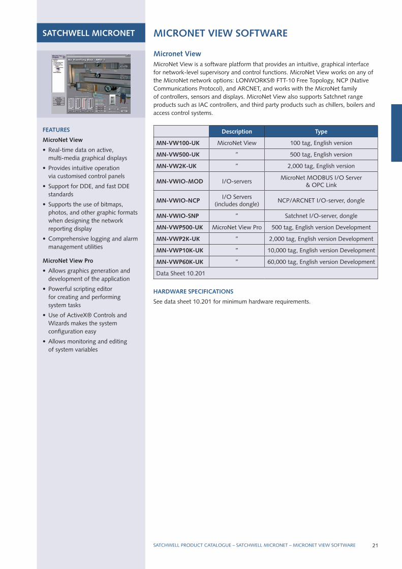
Micronet viewMicroNet View is a software platform that provides an intuitive, graphical interface for network-level supervisory and control functions. MicroNet View works on any of the MicroNet network options: lONWOrKS® FTT-10 Free Topology, NCP (Native Communications Protocol), and ArCNET, and works with the MicroNet family of controllers, sensors and displays. MicroNet View also supports Satchnet range products such as IAC controllers, and third party products such as chillers, boilers and access control systems.
hARDwARE SpECIFICATIONS
See data sheet 10.201 for minimum hardware requirements.
FEATURES
MicroNet view
• real-time data on active, multi-media graphical displays
• Provides intuitive operation via customised control panels
• Support for ddE, and fast ddE standards
• Supports the use of bitmaps, photos, and other graphic formats when designing the network reporting display
• Comprehensive logging and alarm management utilities
MicroNet view pro
• Allows graphics generation and development of the application
• Powerful scripting editor for creating and performing system tasks
• use of ActiveX® Controls and Wizards makes the system configuration easy
• Allows monitoring and editing of system variables
SATChwELL MICRONET MICRONET vIEw SOFTwARE
SATCHWEll PrOduCT CATAlOguE – SATCHWEll MICrONET – MICrONET VIEW SOFTWArE 21
SATCHWELLCAT_0408.indd 21 29/4/08 10:41:09
SATChwELL SIGMA BUILDING AUTOMATION SYSTEM – OvERvIEw
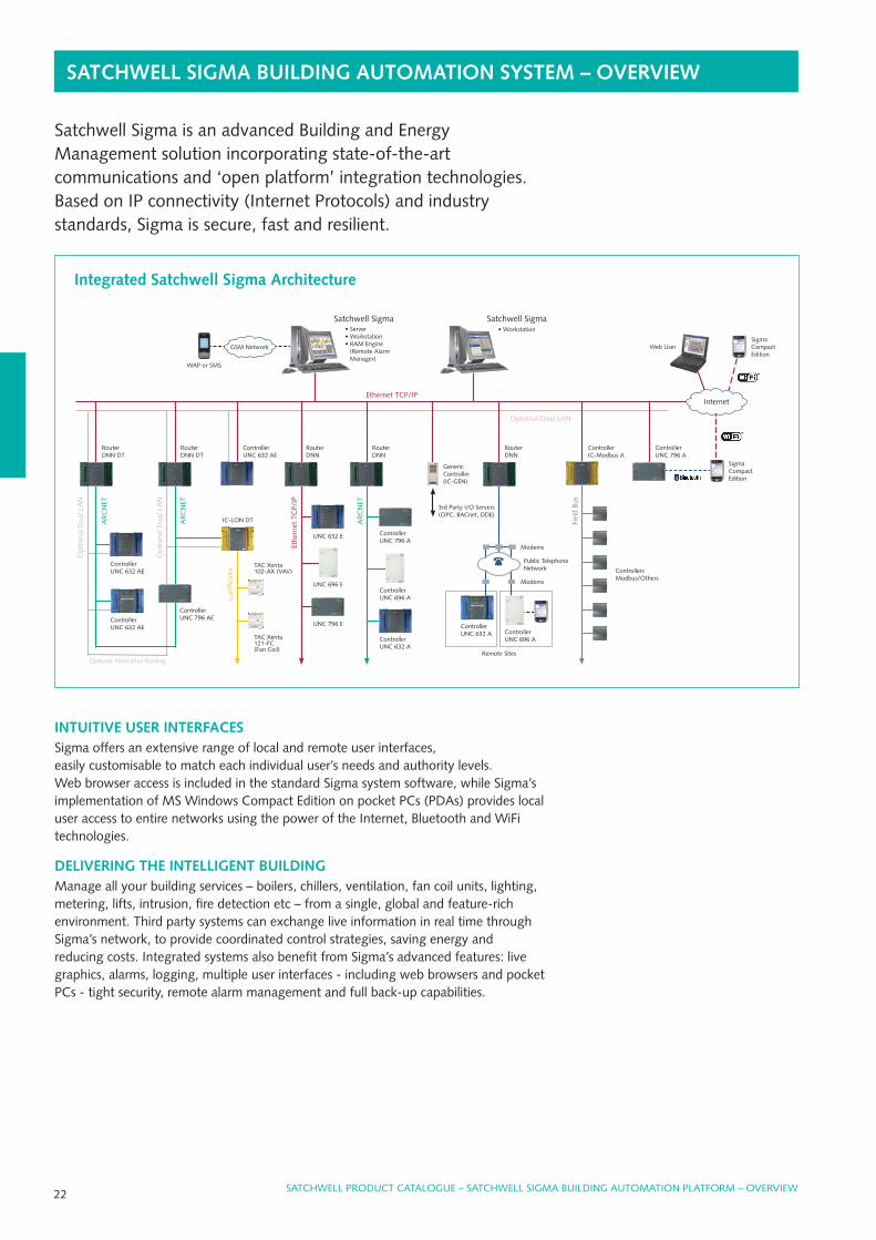
INTUITIvE USER INTERFACESSigma offers an extensive range of local and remote user interfaces, easily customisable to match each individual user’s needs and authority levels. Web browser access is included in the standard Sigma system software, while Sigma’s implementation of MS Windows Compact Edition on pocket PCs (PdAs) provides local user access to entire networks using the power of the Internet, Bluetooth and WiFi technologies.
DELIvERING ThE INTELLIGENT BUILDINGManage all your building services – boilers, chillers, ventilation, fan coil units, lighting,metering, lifts, intrusion, fire detection etc – from a single, global and feature-richenvironment. Third party systems can exchange live information in real time throughSigma’s network, to provide coordinated control strategies, saving energy andreducing costs. Integrated systems also benefit from Sigma’s advanced features: livegraphics, alarms, logging, multiple user interfaces - including web browsers and pocketPCs - tight security, remote alarm management and full back-up capabilities.
Web user
Ethernet TCP/IP
Optional dual lAN
genericController(IC-gEN)
routerdNN
Controller uNC 632 AE
routerdNN dT
Controller uNC 796 A
Controller uNC 632 AE
3rd Party I/O Servers(OPC, BACnet, ddE)
Controller IC-Modbus A
Fiel
d Bu
sControllers Modbus/Others
Controller uNC 796 A
Controller uNC 696 A
Controller uNC 632 A
routerdNN dT
lonW
orks
IC-lON dTAr
CN
ET
Opt
iona
l dua
l lA
N
Controller uNC 796 AE
TAC Xenta 102-AX (VAV)
TAC Xenta 121-FC (Fan Coil)
remote Sites
Opt
iona
l dua
l lA
N
Ar
CN
ET
Modems
Public Telephone Network
Controller uNC 632 A Controller
uNC 696 A
Ar
CN
ET
Optional Alternative routing
routerdNN
Modems
gSM Network
WAP or SMS
Sigma Compact Edition
uNC 632 E
uNC 696 E
uNC 796 E
Ethe
rnet
TC
P/IP
Controller uNC 632 AE
routerdNN
Satchwell Sigma • Workstation
Satchwell Sigma• Server• Workstation• rAM Engine (remote Alarm Manager)
Internet
Sigma Compact Edition
Integrated Satchwell Sigma Architecture
Satchwell Sigma is an advanced Building and Energy Management solution incorporating state-of-the-art communications and ‘open platform’ integration technologies. Based on IP connectivity (Internet Protocols) and industry standards, Sigma is secure, fast and resilient.
22 SATCHWEll PrOduCT CATAlOguE – SATCHWEll SIgMA BuIldINg AuTOMATION PlATFOrM – OVErVIEW
SATCHWELLCAT_0408.indd 22 29/4/08 10:41:24
SATChwELL SIGMA SYSTEM SOFTwARE
SATCHWEll PrOduCT CATAlOguE – SATCHWEll SIgMA – SySTEM SOFTWArE
System SoftwareSatchwell Sigma is a high performance building management system which can be scaled from a single controller in a plant room to a complex wide-area system spanning the largest multi-site buildings. Sigma utilises open distributed intelligence and peer to peer (IP) communications, and is highly configurable with a comprehensive range of options.
Sigma comprises one or more clients connected to a server, all running under Windows® 2000 or Windows XP Professional. Sigma Standard Edition software includes Web ActiveX client software (Sigma’s native graphics on the Web) and supports Web HTMl clients (Sigma HTMl pages on the Web). Sigma also supports a portable Compact client (based on a subset of the Standard Edition), which runs on a Windows CE Handheld PC.
Sigma is multi-tasking and allows multiple clients to be used on the same system. Clients may be configured as multi-purpose for complete system operation, or they may be dedicated to particular functions, facilities and locations. This allows on-line multi-user applications to be speedily carried out whilst providing total system flexibility. The standard software is supplied complete with web, graphics, dynamic and historical logging, comprehensive alarm handling and extensive built-in Help.
By using an Integration Controller (IC), it is possible to interface Sigma to a wide variety of third party equipment and packages such as maintenance packages and reporting applications
FEATURES
General
• Multi-tasking intelligent system
• Easy to use, operates on a standard menu system and tool bar screen
User
• user interface & displays configurable for different users based on their passwords
• Multi-layered index for easy plant identification & navigation
• graphical set-up for Time and Calendar schedules
• Web server capability included in the standard edition Sigma software
• Built-In Help Manual
• Event driven Active graphics
platform
• Windows 2000 Professional or Windows XP Professional
Scalability
• Flexible for small, medium or large sites, either hardwired or remote
• Multi-user/Multi-terminal
• Budget 150 and 400 object versions available
Communications
• Wide area operation including Modem
• ArCNET and / or Ethernet connectivity including dual trunking options
Control & Integration
• distributed direct digital Control
• Integration Controllers to third party systems such as meters, uPSs, fire, security, lighting, controllers, etc.
Order code Licence Description Data Sheets
S-FULL Standard Edition dS 13.101
S-CLI Additional Client – Standard Edition* ”
S-400 light Edition – 400 objects ”
S-150 Personal Edition – 150 objects ”
S-UpG upgrade to Standard Edition ”
S-wINCE Compact Edition for Windows CE devices dS 13.111
S-TOOLKIT Advanced Toolkit option dS 13.104
S-ODBC OdBC option dS 13.102
S-FLExIMA Flexima option dS 13.103
S-ASM Advanced Security Model option dS 13.106
S-RAM remote Alarm Manager option dS 11.001
*Up to 10 clients per server
hARDwARE SpECIFICATIONS
See data sheet for minimum hardware requirements.
23
SATCHWELLCAT_0408.indd 23 29/4/08 10:41:25

SATChwELL SIGMA COMpACT EDITION
SATCHWEll PrOduCT CATAlOguE – SATCHWEll SIgMA – COMPACT EdITION
FEATURES
• Highly portable Human-Machine Interface (HMI)
• Familiar Explorer-style navigation
• display and overrides
• Short Form Editing
• Contingency logging display
• Object Alarm displays
• dynamic object display (Actipane) – via ethernet only
• Access to all controllers on the network
• Ethernet access via lAN or wireless
• Bluetooth wireless option
• Password protected
S-wINCE Compact Edition (CE) LicenceSigma Compact Edition (CE) software, which runs on a Windows® CE Pocket PC, provides a subset of the full client/server Sigma software, creating a highly portable solution.
Sigma CE includes the ability to display object conditions, override object values, edit object parameters using the Short Form Editor, apply time extensions, and view and setup contingency log information.
Sigma CE can communicate with any controller in the Sigma network using a serial connection to a universal Network Controller (uNC), distributed Network Node (dNN) or Integration Controller. Alternatively, Sigma CE can communicate with the Sigma network via Ethernet lAN or Ethernet wireless, or via a Bluetooth wireless serial connection (with an rS-232 converter at the controller).
Any controller on the network can be monitored and controlled, not just the unit that Sigma CE is connected to.
Licence Description Data Sheet
S-wINCE Compact Edition (CE) Software licence dS 13.111
FEATURES
• Alarm information collected automatically from Sigma
• Output drivers to fax, remote printer, Web pages, SMS messaging or E-mail
• Core software includes Web and WAP interfaces
• Self-monitoring of system hardware and software
• Console for system configuration and full alarm history
Remote Alarm Managerremote Alarm Manager is a powerful software package for routing alarm information to management and service personnel. It integrates seamlessly to Sigma and includes comprehensive alarm tracking and history.
Alarms can be acknowledged remotely from a gSM or WAP-enabled mobile phone or from a Web browser. Message content can be customised and alarms can be routed according to alarm priority, type of alarm and time of day.
remote Alarm Manager is an essential system for organisation that use mobile maintenance staff, and where different maintenance personnel are on duty at different times of the day or week. remote Alarm Manager can ensure that the correct personnel are made immediately aware of maintenance tasks, and that alarm conditions are resolved as quickly as possible.
hARDwARE SpECIFICATIONS
See data sheet for minimum hardware requirements.
Description Type
S-RAMremote Alarm Manager,
coreSystem software,
includes 1 output driver
S-RAM-OUT Output driversAdditional output interface
(see data sheet)
data Sheet 11.001
REMOTE ALARM MANAGER
24
hARDwARE SpECIFICATIONS
See data sheet for minimum hardware requirements.
SATCHWELLCAT_0408.indd 24 29/4/08 10:41:26
SATChwELL SIGMA UNIvERSAL NETwORK CONTROLLERS
SATCHWEll PrOduCT CATAlOguE – SATCHWEll SIgMA – uNIVErSAl NETWOrK CONTrOllErS
S-632 Universal Network ControllerThe Satchwell Sigma universal Network Controller (uNC632) is fully intelligent and incorporates its own 32-bit microprocessor providing direct digital Control of plant. It is specifically designed for sites and applications with low object counts. After initial programming from a Satchwell Sigma server, the S-632 scans and monitors dedicated functions and will automatically decide on any control action necessary. It can operate independently of other system components and communicates with any selected Sigma Client only when necessary to provide data such as alarms or logging information, or on demand by the operator.
Each controller can monitor and control up to 32 individual items of plant. The S-632 can operate in a stand-alone mode, or it can be networked as part of a Sigma building management system. Networking can be either to a local area network or, as a single controller, directly into the wide area network of Sigma. For systems which need additional resilience, the dual Trunking options provide redundancy and allow for cabling and other communications channel failures.
Description
S-632-A uNC632 universal Controller, ArCNET
S-632-E uNC632 universal Controller, Ethernet
S-632-AE uNC632 universal Controller , ArCNET/Ethernet & Sigma lAN
data Sheet 13.312
ACCESSORIES
S-UNC-4DO digital Output Module
S-632-KB Sigma uNC Keyboard option
S-TK Trunking kit for S-x32, S-dNN3, S-IC3
INSTALLATION DETAILS
power supply: 230Vac ±10%. Switch selectable to 115Vac ±10%
Supply frequency: 50/60Hz ±10%
power Consumption: 15VA typical, 24VA maximum (Triac outputs require a separate 24Vac supply).
protection class: IP 40 by use of the trunking kit.
Mounting: Wall or panel mounting
power Failure Reserve: rechargeable battery gives typically 90 day back up of object data stored in rAM, and of the real time clock
INpUTS AND OUTpUTS
I/O point type Description Quantity
Analogue InputsJumper link configurable for resistance (0 to 10kΩ), current (0 to 20mA) or voltage (0 to 10V). Can also be jumper link configured as digital inputs
8
digital InputsVoltage free SPST contacts (open/closed). Can be used for pulse totalisation (maximum pulse frequency 10Hz).
10
Analogue Outputs0 to 10Vdc signals (Maximum 1mA per channel). Can be used as digital outputs by using the digital Output Module
6
Triac Outputs24Vac. Maximum switching current 0.6A, minimum 20mA at 24Vac. External plant should be switched via externally mounted contactors.
8
FEATURES
• Intelligent 32-bit microprocessor technology
• up to 32 configurable input/output objects & 55 software objects
• Stand-alone capability
• local and wide area networking capability
• Optional ArCNET® or Ethernet communications
• Flexible and configurable application software
• IP 40 Protection Class
• Optional keyboard and display
• Permanent local storage of configuration (object) and accumulated data
• Integral IP (Internet Protocol) addressing
• dual Trunk capability (redundant networking)
• dual image Hot-Swap Flash EPrOM for fast and easy firmware upgrades
• Contingency logs held in rAM, viewable via Sigma Client, WinCE and/or Web.
• 115Vac/230Vac selectable
• ArCNET and Sigma lAN fully opto-isolated
• On board modem port
25
SATCHWELLCAT_0408.indd 25 29/4/08 10:41:26
FEATURES
• Intelligent 32-bit microprocessor technology
• up to 96 configurable input/output points and up to 250 points including software points
• Integral IP (Internet Protocol) addressing
• dual image Hot-Swap Flash EPrOM for fast and easy firmware upgrades
• IP 66 protection class
• Stand-alone capability
• local and wide area networking capability
• Optional ArCNET® or Ethernet communications
• Flexible and configurable application software
• Permanent local storage of configuration (object) and accumulated data
• dual Trunk capability (redundant networking)
• dual image Hot-Swap Flash EPrOM for fast and easy firmware upgrades
• Contingency logs held in rAM, viewable via Sigma Client, WinCE and/or Web.
• Two communication ports as standard
• ArCNET and Sigma lAN fully opto-isolated
• On board modem port
S-696 Universal Network ControllerThe Satchwell Sigma universal Network Controller (uNC696) is fully intelligent, and incorporates its own 32-bit microprocessor providing direct digital Control of plant. The S-696 is in a wall mounting IP 66 enclosure.
The S-696 scans and monitors dedicated functions and will automatically decide on any control action necessary. It can operate independently of other system components, and communicates with any selected Sigma Client only when necessary to provide data such as alarms or logging information, or on demand by the operator. Each controller can monitor and control up to 96 individual items of plant and/or sensors. Plant monitoring and control requirements are met by the appropriate selection of input and output cards. Further flexibility is achieved by enabling analogue objects to be used in a digital mode (on/off).
The S-696 CPu card (S-x96CPu-AE) contains two communications media (ArCNET and Ethernet), either of which can be used with the on-board Sigma lAN to provide optional dual-lAN operation.
Description Communications
S-696 uNC696 universal Network Controller
S-x96CpU-AE uNC696 CPu Card Opto-isolatedArCNET/ Ethernet and Sigma lAN
data Sheet: 13.324
SATChwELL SIGMA UNIvERSAL NETwORK CONTROLLERS
SATCHWEll PrOduCT CATAlOguE – SATCHWEll SIgMA – uNIVErSAl NETWOrK CONTrOllErS26
ACCESSORIES
S-UNC-AI Analogue Input Card
S-UNC-DI digital Input Card
S-UNC-AO Analogue Output Card
S-UNC-DO digital Output Card
S-UNC-CMD Command Interface Module
S-UNC-CBL ribbon Cable
S-UNC-BKT Bracket
S-UNC-BAT Battery Pack (typical 12 hour power failure back-up)
INSTALLATION DETAILS
power supply: 230Vac ±10%.
Supply frequency: 50/60Hz ±10%
power Consumption: 25VA maximum
protection class: IP 66
Mounting: Wall
power Failure Reserve Full Operation: Nickel-Cadmium rechargeable battery giving typically 1.4 hour power failure back-up. An optional battery (S-uNC-BAT) provides typical 12 hour power failure back-up. Full monitoring control and communication maintained during battery operation.
Memory/Clock: Typical 90 day memory and real Time Clock retention at the end of normal battery reserve using Ni-MH battery.
I/O point type Description
Analogue Inputs* 0-10KΩ, 0-10V, 0-20mA – Jumper selected.
digital/Pulse Inputs* Volt-free Make/Break contacts; metering inputs.
Analogue Outputs* 0-10Vdc, plus up to two 0 to 20mA.
digital Outputs*SPST Voltage Free relay contacts located internally or on a separate module (S-uNC-dO).
relay OutputsEight SPCO Voltage Free relay contacts per module (S-uNC-CMd).
For use with x96 series controllers (Sigma & BAS)
*The S-696 can accept any number or mix of 16 channel Analogue Input, Analogue Output,
Digital Input & Digital Output cards to a maximum of 6 cards per controller
(6 x 16 = 96 total I/O).
SATCHWELLCAT_0408.indd 26 29/4/08 10:41:28

27SATCHWEll PrOduCT CATAlOguE – SATCHWEll SIgMA – uNIVErSAl NETWOrK CONTrOllErS
SATChwELL SIGMA UNIvERSAL NETwORK CONTROLLERS
S-796 Universal Network ControllerThe Satchwell Sigma universal Network Controller (uNC796) is fully intelligent and incorporates its own 32-bit microprocessor providing direct digital Control of plant. The S-796 is a rack/Panel mount unit (19 inch).
The S-796 scans and monitors dedicated functions and will automatically decide on any control action necessary. It can operate independently of other system components, and communicates with any selected Sigma Client only when necessary to provide data such as alarms or logging information, or on demand by the operator. Each controller can monitor and control up to 96 individual items of plant and/or sensors. Plant monitoring and control requirements are met by the appropriate selection of input and output cards. Further flexibility is achieved by enabling analogue objects to be used in a digital mode (on/off).
The S-796 CPu card (S-x96CPu-AE) contains two communications media (ArCNET and Ethernet), either of which can be used with the on-board Sigma Controller lAN to provide optional dual-lAN operation.
Description Communications
S-796 uNC796 universal Network Controller
S-x96CpU-AE uNC796 CPu Card Opto-isolatedArCNET/ Ethernet and Sigma lAN
data Sheet: 13.325
FEATURES
• Intelligent 32-bit microprocessor technology
• up to 96 configurable input/ output points and up to 250 points including software points
• Two communication ports as standard
• Extra communications board available to give two further communications ports
• Flexible and configurable application software
• Stand-alone capability
• local and wide area networking capability
• Optional ArCNET® or Ethernet communications
• Permanent local storage of configuration (object) and accumulated data
• dual Trunk capability (redundant networking)
• dual image Hot-Swap Flash EEPrOM for fast and easy firmware upgrades
• Contingency logs held in rAM, viewable via Sigma Client, WinCE and/or Web.
• ArCNET and Sigma lAN fully opto-isolated
• On board modem port
• IP20 protection class
SATCHWEll PrOduCT CATAlOguE – SATCHWEll SIgMA – uNIVErSAl NETWOrK CONTrOllErS
I/O point type Description
Analogue Inputs* 0-10KΩ, 0-10V, 0-20mA – Jumper selected.
digital/Pulse Inputs* Volt-free Make/Break contacts; metering inputs.
Analogue Outputs* 0-10Vdc, plus up to two 0 to 20mA.
digital Outputs*SPST Voltage Free relay contacts located internally or on a separate module (S-uNC-dO).
relay OutputsEight SPCO Voltage Free relay contacts per module (S-uNC-CMd).
For use with x96 series controllers (Sigma & BAS)
*The S-796 can accept any number or mix of 16 channel Analogue Input, Analogue Output,
Digital Input & Digital Output cards to a maximum of 6 cards per controller
(6 x 16 = 96 total I/O).
ACCESSORIES
S-UNC-AI Analogue Input Card
S-UNC-DI digital Input Card
S-UNC-AO Analogue Output Card
S-UNC-DO digital Output Card
S-UNC-CMD 8-Channel dO Module
S-UNC-CBL ribbon Cable
S-UNC-BKT Bracket
S-UNC-BAT Battery Pack (typical 12 hour power failure back-up)
INSTALLATION DETAILS
power supply: 230Vac ±10%.
Supply frequency: 50/60Hz ±10%
power Consumption: 25VA maximum
protection class: IP 20
Mounting: Panel or rack mounting
power Failure Reserve Full Operation: Nickel-Cadmium rechargeable battery giving typically 1.4 hour power failure back-up. An optional battery (S-uNC-BAT) provides typical 12 hour power failure back-up. Full monitoring control and communication maintained during battery operation.
Memory/Clock: Typical 90 day memory and real Time Clock retention at the end of normal battery reserve using Ni-MH battery.
SATCHWELLCAT_0408.indd 27 29/4/08 10:41:31
SATChwELL SIGMA ANALOGUE AND DIGITAL I/O CARDS
FEATURES
• 16 channels per board
• up to 6 boards per Outstation
• Comprehensive range of inputs
• utility Meter Monitoring
• Analogue inputs jumper selectable to accept 0 to 10kΩ, 0 to 10Vdc or 0 to 20mA signals
• Maximum demand Meter Monitoring
• load Shedding routines
• Analogue Inputs may be configured to provide digital Inputs
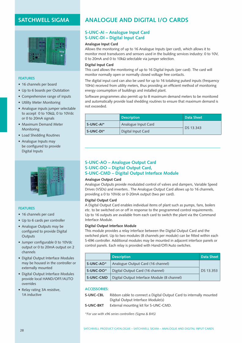
S-UNC-AI – Analogue Input Card S-UNC-DI – Digital Input CardAnalogue Input CardAllows the monitoring of up to 16 Analogue Inputs (per card), which allows it to monitor most transducers and sensors used in the building services industry: 0 to 10V, 0 to 20mA and 0 to 10kΩ selectable via jumper selection.
Digital Input CardThis card allows the monitoring of up to 16 digital Inputs (per card). The card will monitor normally open or normally closed voltage free contacts.
The digital input card can also be used for up to 16 totalising pulsed inputs (frequency 10Hz) received from utility meters, thus providing an efficient method of monitoring energy consumption of buildings and installed plant.
Software programmes also permit up to 8 maximum demand meters to be monitored and automatically provide load shedding routines to ensure that maximum demand is not exceeded.
Description Data Sheet
S-UNC-AI* Analogue Input CarddS 13.343
S-UNC-DI* digital Input Card
FEATURES
• 16 channels per card
• up to 6 cards per controller
• Analogue Outputs may be configured to provide digital Outputs
• Jumper configurable 0 to 10Vdc output or 0 to 20mA output on 2 channels
• digital Output Interface Modules may be housed in the controller or externally mounted
• digital Output Interface Modules provide local HANd/OFF/AuTO overrides
• relay rating 3A resistive, 1A inductive
S-UNC-AO – Analogue Output Card S-UNC-DO – Digital Output Card, S-UNC-CMD – Digital Output Interface ModuleAnalogue Output CardAnalogue Outputs provide modulated control of valves and dampers, Variable Speed drives (VSds) and inverters.. The Analogue Output Card allows up to 16 channels, providing a 0 to 10Vdc or 0-20mA output (two per card).
Digital Output CardA digital Output Card enables individual items of plant such as pumps, fans, boilers etc. to be switched on or off in response to the programmed control requirements. up to 16 outputs are available from each card to switch the plant via the Command Interface Module.
Digital Output Interface ModuleThis module provides a relay interface between the digital Output Card and the switched plant. up to two modules (8 channels per module) can be fitted within each S-696 controller. Additional modules may be mounted in adjacent interface panels or control panels. Each relay is provided with Hand/Off/Auto switches.
Description Data Sheet
S-UNC-AO* Analogue Output Card (16 channel)
dS 13.353S-UNC-DO* digital Output Card (16 channel)
S-UNC-CMD digital Output Interface Module (8 channel)
ACCESSORIES:
S-UNC-CBL ribbon cable to connect a digital Output Card to internally mounted digital Output Interface Module(s)
S-UNC-BKT External mounting kit for S-uNC-CMd.
*For use with x96 series controllers (Sigma & BAS)
28 SATCHWEll PrOduCT CATAlOguE – SATCHWEll SIgMA – ANAlOguE ANd dIgITAl INPuT CArdS
SATCHWELLCAT_0408.indd 28 29/4/08 10:41:32
SATCHWEll PrOduCT CATAlOguE – SATCHWEll SIgMA – ANAlOguE ANd dIgITAl INPuT CArdS
SATChwELL SIGMA DISTRIBUTED NETwORK NODE
29SATCHWEll PrOduCT CATAlOguE – SATCHWEll SIgMA – uNIVErSAl NETWOrK CONTrOllErS
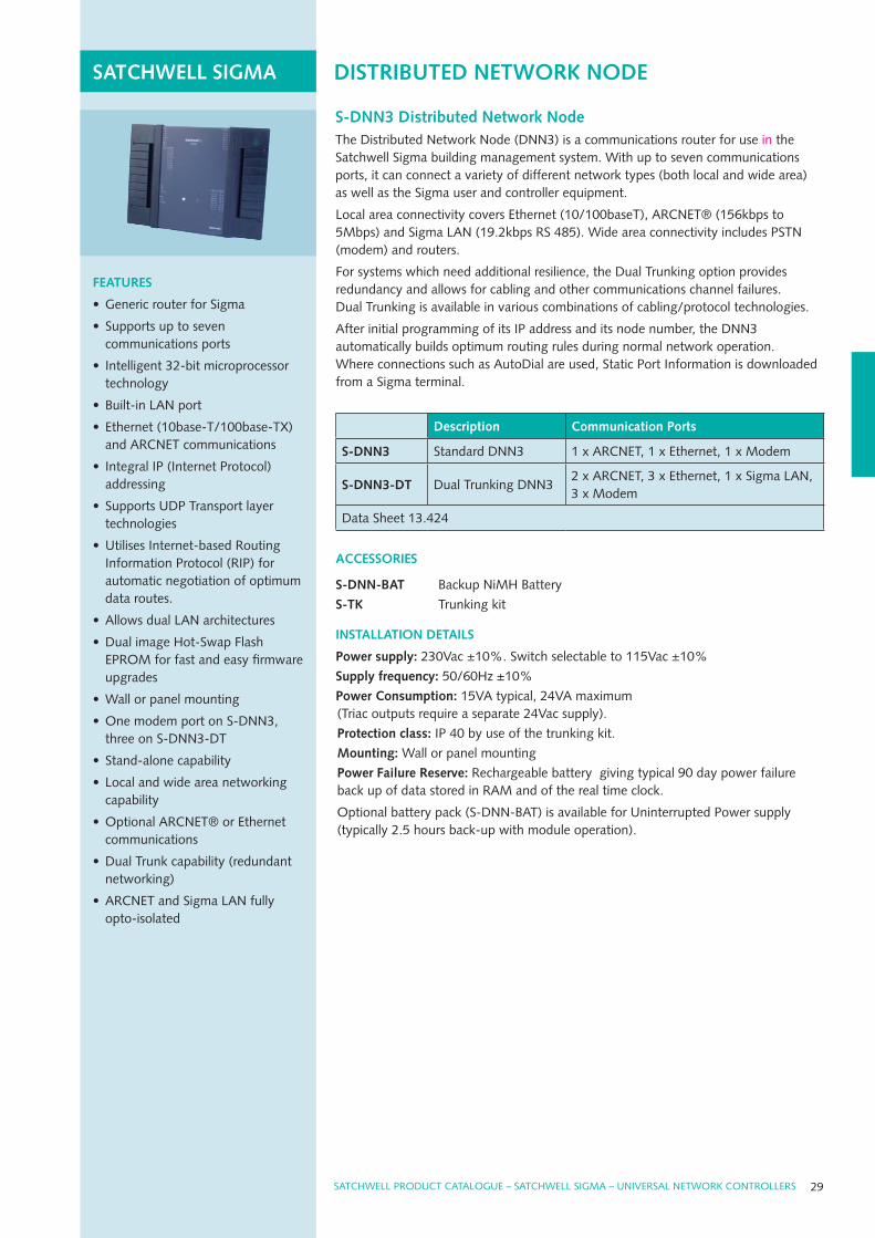
S-DNN3 Distributed Network NodeThe distributed Network Node (dNN3) is a communications router for use in the Satchwell Sigma building management system. With up to seven communications ports, it can connect a variety of different network types (both local and wide area) as well as the Sigma user and controller equipment.
local area connectivity covers Ethernet (10/100baseT), ArCNET® (156kbps to 5Mbps) and Sigma lAN (19.2kbps rS 485). Wide area connectivity includes PSTN (modem) and routers.
For systems which need additional resilience, the dual Trunking option provides redundancy and allows for cabling and other communications channel failures. dual Trunking is available in various combinations of cabling/protocol technologies.
After initial programming of its IP address and its node number, the dNN3 automatically builds optimum routing rules during normal network operation. Where connections such as Autodial are used, Static Port Information is downloaded from a Sigma terminal.
Description Communication ports
S-DNN3 Standard dNN3 1 x ArCNET, 1 x Ethernet, 1 x Modem
S-DNN3-DT dual Trunking dNN32 x ArCNET, 3 x Ethernet, 1 x Sigma lAN, 3 x Modem
data Sheet 13.424
ACCESSORIES
S-DNN-BAT Backup NiMH Battery
S-TK Trunking kit
INSTALLATION DETAILS
power supply: 230Vac ±10%. Switch selectable to 115Vac ±10%
Supply frequency: 50/60Hz ±10%
power Consumption: 15VA typical, 24VA maximum (Triac outputs require a separate 24Vac supply).
protection class: IP 40 by use of the trunking kit.
Mounting: Wall or panel mounting
power Failure Reserve: rechargeable battery giving typical 90 day power failure back up of data stored in rAM and of the real time clock.
Optional battery pack (S-dNN-BAT) is available for uninterrupted Power supply (typically 2.5 hours back-up with module operation).
FEATURES
• generic router for Sigma
• Supports up to seven communications ports
• Intelligent 32-bit microprocessor technology
• Built-in lAN port
• Ethernet (10base-T/100base-TX) and ArCNET communications
• Integral IP (Internet Protocol) addressing
• Supports udP Transport layer technologies
• utilises Internet-based routing Information Protocol (rIP) for automatic negotiation of optimum data routes.
• Allows dual lAN architectures
• dual image Hot-Swap Flash EPrOM for fast and easy firmware upgrades
• Wall or panel mounting
• One modem port on S-dNN3, three on S-dNN3-dT
• Stand-alone capability
• local and wide area networking capability
• Optional ArCNET® or Ethernet communications
• dual Trunk capability (redundant networking)
• ArCNET and Sigma lAN fully opto-isolated
SATCHWELLCAT_0408.indd 29 29/4/08 10:41:33
INTEGRATION
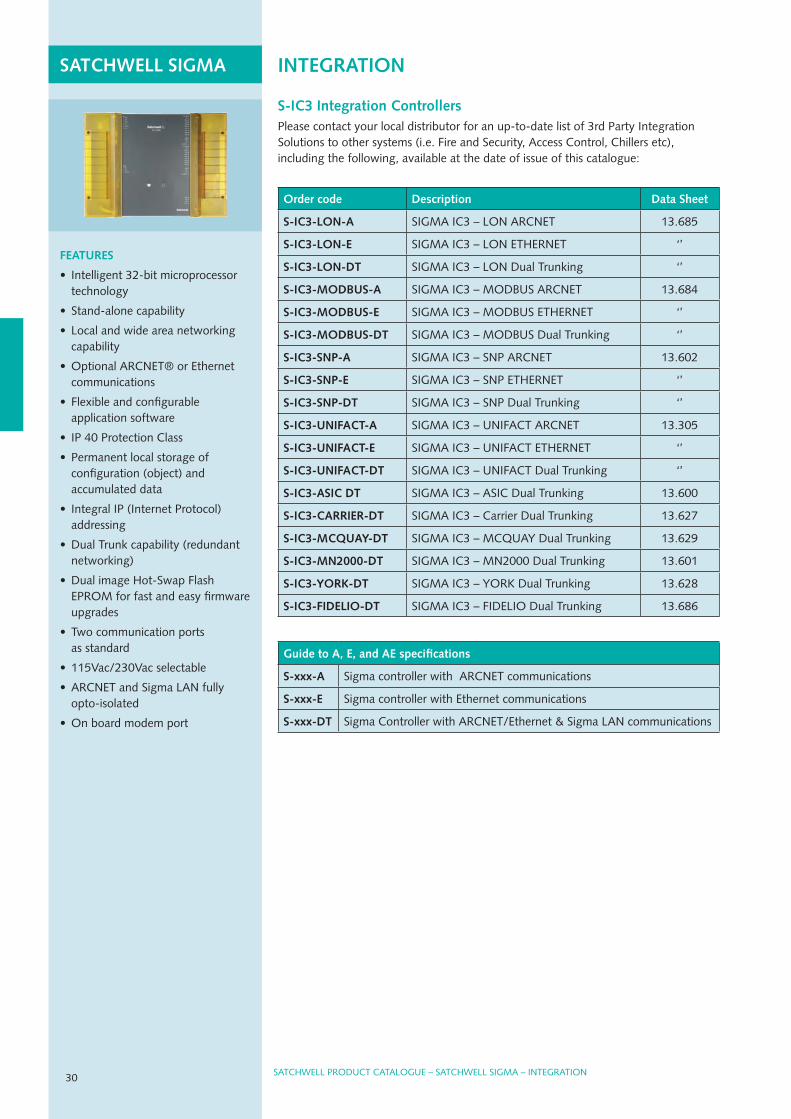
S-IC3 Integration ControllersPlease contact your local distributor for an up-to-date list of 3rd Party Integration Solutions to other systems (i.e. Fire and Security, Access Control, Chillers etc), including the following, available at the date of issue of this catalogue:
SATChwELL SIGMA
SATCHWEll PrOduCT CATAlOguE – SATCHWEll SIgMA – INTEgrATION
Order code Description Data Sheet
S-IC3-LON-A SIgMA IC3 – lON ArCNET 13.685
S-IC3-LON-E SIgMA IC3 – lON ETHErNET ‘’
S-IC3-LON-DT SIgMA IC3 – lON dual Trunking ‘’
S-IC3-MODBUS-A SIgMA IC3 – MOdBuS ArCNET 13.684
S-IC3-MODBUS-E SIgMA IC3 – MOdBuS ETHErNET ‘’
S-IC3-MODBUS-DT SIgMA IC3 – MOdBuS dual Trunking ‘’
S-IC3-SNp-A SIgMA IC3 – SNP ArCNET 13.602
S-IC3-SNp-E SIgMA IC3 – SNP ETHErNET ‘’
S-IC3-SNp-DT SIgMA IC3 – SNP dual Trunking ‘’
S-IC3-UNIFACT-A SIgMA IC3 – uNIFACT ArCNET 13.305
S-IC3-UNIFACT-E SIgMA IC3 – uNIFACT ETHErNET ‘’
S-IC3-UNIFACT-DT SIgMA IC3 – uNIFACT dual Trunking ‘’
S-IC3-ASIC DT SIgMA IC3 – ASIC dual Trunking 13.600
S-IC3-CARRIER-DT SIgMA IC3 – Carrier dual Trunking 13.627
S-IC3-MCQUAY-DT SIgMA IC3 – MCQuAy dual Trunking 13.629
S-IC3-MN2000-DT SIgMA IC3 – MN2000 dual Trunking 13.601
S-IC3-YORK-DT SIgMA IC3 – yOrK dual Trunking 13.628
S-IC3-FIDELIO-DT SIgMA IC3 – FIdElIO dual Trunking 13.686
Guide to A, E, and AE specifications
S-xxx-A Sigma controller with ArCNET communications
S-xxx-E Sigma controller with Ethernet communications
S-xxx-DT Sigma Controller with ArCNET/Ethernet & Sigma lAN communications
FEATURES
• Intelligent 32-bit microprocessor technology
• Stand-alone capability
• local and wide area networking capability
• Optional ArCNET® or Ethernet communications
• Flexible and configurable application software
• IP 40 Protection Class
• Permanent local storage of configuration (object) and accumulated data
• Integral IP (Internet Protocol) addressing
• dual Trunk capability (redundant networking)
• dual image Hot-Swap Flash EPrOM for fast and easy firmware upgrades
• Two communication ports as standard
• 115Vac/230Vac selectable
• ArCNET and Sigma lAN fully opto-isolated
• On board modem port
30
SATCHWELLCAT_0408.indd 30 29/4/08 10:41:34
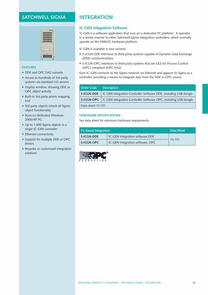
pC-based Integration Data Sheet
S-ICGN-DDE IC-gEN Integration software,ddE13.151
S-ICGN-OpC IC-gEN Integration software, OPC
31
INTEGRATIONSATChwELL SIGMA
SATCHWEll PrOduCT CATAlOguE – SATCHWEll SIgMA – INTEgrATION
IC-GEN Integration SoftwareIC-gEN is a software application that runs on a dedicated PC platform. It operates in a similar manner to other Satchwell Sigma integration controllers, which normally operate on the dNN/IC hardware platform.
IC-gEN is available in two variants:
• S-ICgN-ddE interfaces to third party systems capable of dynamic data Exchange (ddE) communications
• S-ICgN-OPC interfaces to third party systems that are OlE for Process Control (OPC) compliant (OPC dA2).
Each IC-gEN connects to the Sigma network via Ethernet and appears to Sigma as a controller, providing a means to integrate data from the ddE or OPC source.
Order Code Description
S-ICGN-DDE IC gEN Integration Controller Software ddE, including uSB dongle.
S-ICGN-OpC IC gEN Integration Controller Software OPC, including uSB dongle.
data sheet 13.151
hARDwARE SpECIFICATIONS
See data sheet for minimum hardware requirements.
FEATURES
• ddE and OPC dA2 variants
• Access to hundreds of 3rd party systems via standard I/O servers
• display window, showing ddE or OPC object activity
• Built-in 3rd party points mapping tool
• 3rd party objects inherit all Sigma object functionality
• runs on dedicated Windows 2000/XP PC
• up to 1,000 Sigma objects in a single IC-gEN controller
• Ethernet connectivity
• Support for multiple ddE or OPC drivers
• Bespoke or customised integration solutions
SATCHWELLCAT_0408.indd 31 29/4/08 10:41:35
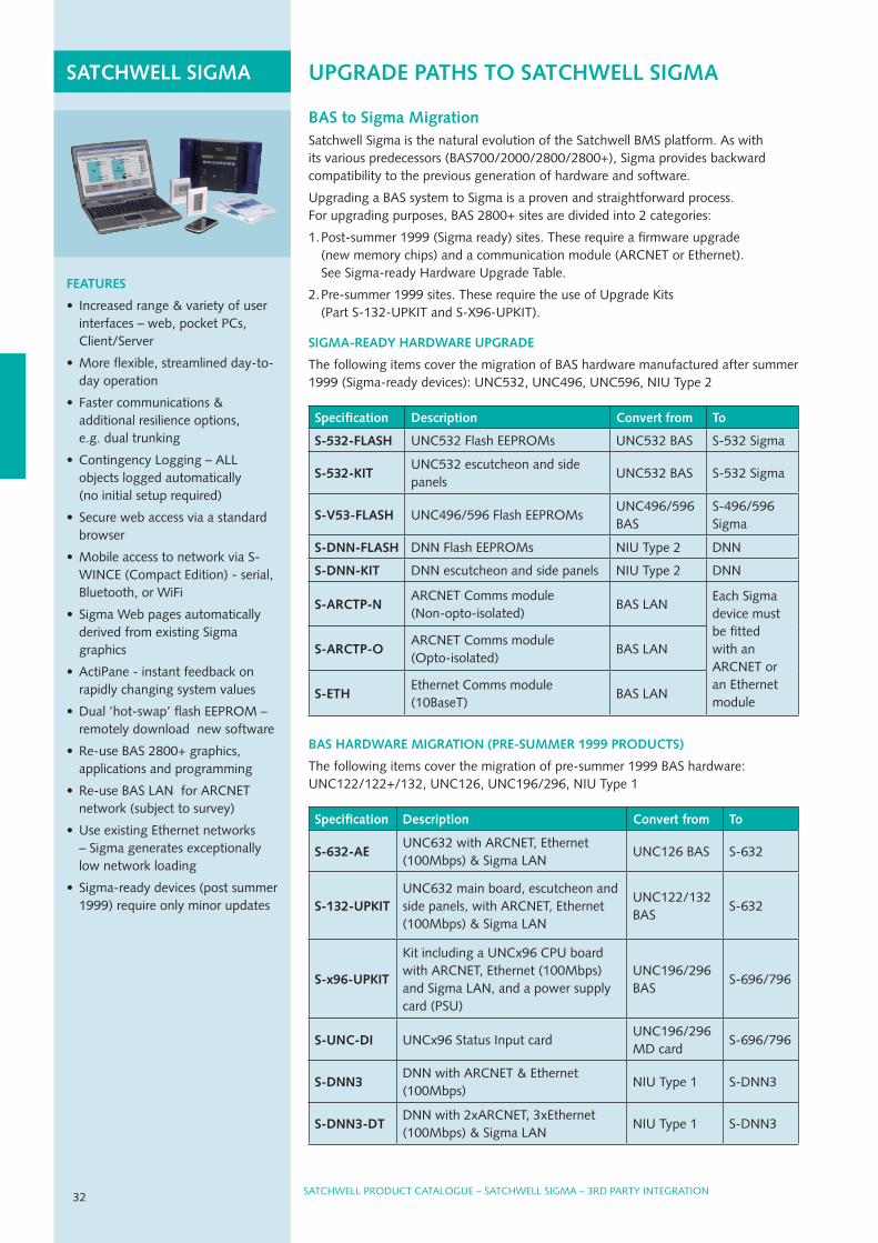
UpGRADE pAThS TO SATChwELL SIGMASATChwELL SIGMA
BAS to Sigma MigrationSatchwell Sigma is the natural evolution of the Satchwell BMS platform. As with its various predecessors (BAS700/2000/2800/2800+), Sigma provides backward compatibility to the previous generation of hardware and software.
upgrading a BAS system to Sigma is a proven and straightforward process. For upgrading purposes, BAS 2800+ sites are divided into 2 categories:
1. Post-summer 1999 (Sigma ready) sites. These require a firmware upgrade (new memory chips) and a communication module (ArCNET or Ethernet). See Sigma-ready Hardware upgrade Table.
2. Pre-summer 1999 sites. These require the use of upgrade Kits (Part S-132-uPKIT and S-X96-uPKIT).
SIGMA-READY hARDwARE UpGRADE
The following items cover the migration of BAS hardware manufactured after summer 1999 (Sigma-ready devices): uNC532, uNC496, uNC596, NIu Type 2
Specification Description Convert from To
S-532-FLASh uNC532 Flash EEPrOMs uNC532 BAS S-532 Sigma
S-532-KITuNC532 escutcheon and side panels
uNC532 BAS S-532 Sigma
S-v53-FLASh uNC496/596 Flash EEPrOMsuNC496/596 BAS
S-496/596 Sigma
S-DNN-FLASh dNN Flash EEPrOMs NIu Type 2 dNN
S-DNN-KIT dNN escutcheon and side panels NIu Type 2 dNN
S-ARCTp-NArCNET Comms module (Non-opto-isolated)
BAS lANEach Sigma device must be fitted with an ArCNET or an Ethernet module
S-ARCTp-OArCNET Comms module (Opto-isolated)
BAS lAN
S-EThEthernet Comms module (10BaseT)
BAS lAN
BAS hARDwARE MIGRATION (pRE-SUMMER 1999 pRODUCTS)
The following items cover the migration of pre-summer 1999 BAS hardware: uNC122/122+/132, uNC126, uNC196/296, NIu Type 1
Specification Description Convert from To
S-632-AEuNC632 with ArCNET, Ethernet (100Mbps) & Sigma lAN
uNC126 BAS S-632
S-132-UpKITuNC632 main board, escutcheon and side panels, with ArCNET, Ethernet (100Mbps) & Sigma lAN
uNC122/132 BAS
S-632
S-x96-UpKIT
Kit including a uNCx96 CPu board with ArCNET, Ethernet (100Mbps) and Sigma lAN, and a power supply card (PSu)
uNC196/296 BAS
S-696/796
S-UNC-DI uNCx96 Status Input carduNC196/296 Md card
S-696/796
S-DNN3dNN with ArCNET & Ethernet (100Mbps)
NIu Type 1 S-dNN3
S-DNN3-DTdNN with 2xArCNET, 3xEthernet (100Mbps) & Sigma lAN
NIu Type 1 S-dNN3
SATCHWEll PrOduCT CATAlOguE – SATCHWEll SIgMA – 3rd PArTy INTEgrATION32
FEATURES
• Increased range & variety of user interfaces – web, pocket PCs, Client/Server
• More flexible, streamlined day-to-day operation
• Faster communications & additional resilience options, e.g. dual trunking
• Contingency logging – All objects logged automatically (no initial setup required)
• Secure web access via a standard browser
• Mobile access to network via S-WINCE (Compact Edition) - serial, Bluetooth, or WiFi
• Sigma Web pages automatically derived from existing Sigma graphics
• ActiPane - instant feedback on rapidly changing system values
• dual ’hot-swap’ flash EEPrOM – remotely download new software
• re-use BAS 2800+ graphics, applications and programming
• re-use BAS lAN for ArCNET network (subject to survey)
• use existing Ethernet networks – Sigma generates exceptionally low network loading
• Sigma-ready devices (post summer 1999) require only minor updates
SATCHWELLCAT_0408.indd 32 29/4/08 10:41:36

SATCHWEll PrOduCT CATAlOguE – SATCHWEll SIgMA – 3rd PArTy INTEgrATION 33
IAC pROGRAMMABLE CONTROLLERS
IAC 420 Universal Multi-Loop Intelligent Advanced ControllerThe IAC 420 is designed for use in both small and large buildings. It has a stand-alone capability, or may be configured from a central computer over the serial link. The IAC 420 has pre-sets for common applications or can be fully customised.
INSTALLATION DETAILS
power supply: 24Vac (±10%) 47/63Hz
power Consumption: 6VA max (excluding any connected outputs)
15 volt dc Output: 25 mA max
power failure reserve: E2PrOM preserves configuration data and user settings.
Inputs: 6 x configurable inputs
Outputs: 3 x 0 to 10V outputs, 6 x digital (triacs on/off) outputs
ACCESSORIES
841-1-201 real Time Clock Board
Terminals Control Range Outputs
IAC 420 – F Fixed
3 loop
-40 to +150°C
20 to 90% rh
250 to 9750 Ohms
0 to 10,000 lux
3 x 0 to 10Vdc
3 x 24V pulsed
24V switched
1 x 15VdcIAC 420 – p Plug-in
data Sheet 2.801
SATCHWEll PrOduCT CATAlOguE – SATCHWEll SIgMA – IAC PrOgrAMMABlE CONTrOllErS
IAC CONTROLLERS
FEATURES
• Serial link
• Configured via VisiSat
• Configurable switched outputs
• Six configurable inputs
• 15Vdc supply output
• 0 to 10Vdc or stepped fan control
• Three off 2-stage controllers
• Optional real Time Clock (rTC) board
FEATURES
• 6 PId control loops
• Compensation and optimisation modules
• Configured via VisiSat
• Standard selectable applications
• Six temperature (resistive) sensor inputs
• Six 0 to 10Vdc inputs
• Eight Voltage free switched inputs
INSTALLATION DETAILS
power supply: 24Vac (±10%) 50/60Hz
15 volt dc output: 30 mA max
power Consumption: 10VA
power failure reserve: Non volatile rAM preserves memory up to 10 years.
Inputs Sensors: Six temperature (resistive). Six 0 to 10 Volt dc, max input 10 Volts dc Digital input: Eight voltage free contacts, opto isolated, can be used for pulse counting, 0.5Hz max.
Actuator Outputs: Four 0 to 10 Volt dc. Eight digital (triac on/off) outputs
IAC 600 Universal Multi-Loop Intelligent Advanced ControllerThe IAC 600 is a Multi-loop Configurable Controller designed primarily for use in typical multi-loop situations such as air-conditioning systems and Central PlantHeating/Cooling Systems.
The IAC 600 includes full plant sequence control and rotation based on plant hours run. It also has a number of preset applications in the software to cater for typical control schemes.
Control Range Outputs
IAC 600-BIAC 600-S
6 x PId loops
-40 to +150°C20 to 90% rh250 to 9750 Ohms0 to 10,000 lux
4 x 0 to 10Vdc8 x on/off triac1 x 15Vdc
data Sheet 2.951
SATCHWELLCAT_0408.indd 33 29/4/08 10:41:37

IAC TOUCh SCREEN DISpLAY
FEATURES
• Mounts on IAC base unit or optional panel mounting
• Touch sensitive graphic lCd screen
• Menu operation for interrogation and setting
• Back-lit screen for easy viewing
• Communicate with up to 31 IACs
• Battery backed clock
• displays up to 256 parameters
Touch Screen for IAC 600 ControllerThis optional Touch Screen gives access to up to 31* IAC base units on its own sub-lAN (including the IAC 600, 400, 420 and 200). The Touch Screen can be mounted direct on the IAC 600 base unit.
The Touch Screen allows the user to interrogate the IACs. Information on sensor values and outputs can be displayed and parameters can be altered if required. The Touch Screen’s battery backed clock is used by the IACs on the sub-lAN as a back-up to their own internal clocks.
*Dependent on the number of parameters to be displayed.
INSTALLATION DETAILS
power supply: Powered from the IAC unit or separate 24 Volt Vac supply
power failure reserve: Non volatile rAM with built-in real Time Clock gives 3 year back up of clock and memory under
normal conditions of use. power Consumption: 2-5 VA
ACCESSORIES
DDC 2601 remote Touch Screen Adaptor Kit
Description
IAC-TS Touch Screen for IAC 600 Controller
data Sheet 2.951
IAC DISpLAY
FEATURES
• Fully networkable or stand- alone controllers
• Selectable control applications (fan-coil applications)
• low installation cost
• Simple setup using PdA hand- held computer or PC via infra-red or rS 232 link
• designed to maximise energy savings
• Optional networking to an MicroNet system
• Supports S-link sensors
UniFact® pro Terminal Unit ControllersThe uNIFACTPrO Terminal unit Controllers have been designed to meet virtually any fan-coil heating/cooling applications. The controllers can be used as stand-alone devices or can be networked to MicroNet systems.
The controller has three main switchable modes: comfort (day), night (off) and economy.
INSTALLATION DETAILS
Control range: 0 to 40°C
power supply: 230Vac
power Consumption: 230 Vac @ 12 VA maximum including outputs
power failure reserve: EEPrOM preserves configuration data and user settings
Controller type Inputs/outputs
URC-41N-10x with on/off fan control and S-link support2 x dI
1 x rI – temperature
1 x AI – setpoint
4 x dO – triacs
3 x dO – relays
URC-51N-10x with 3-speed fan control and S-link support
Where X denotes the pre-loaded application(possible to change on the field)
0 = 4-pipe FCu, 1 = 2-pipe with changeover,
2 = dX cooling and electric heater, 3 = airside control
URC-IR-100 Infra-red/rS 232 receiver
URC-SET-100 NCP Palm Commissioning Software
data Sheet 10.130
NETwORKABLE TERMINAL UNIT CONTROLLERSTERMINAL UNIT CONTROLLERS
34 SATCHWEll PrOduCT CATAlOguE – SATCHWEll SIgMA – IAC TOuCH SCrEEN dISPlAy
SATCHWELLCAT_0408.indd 34 29/4/08 10:41:38
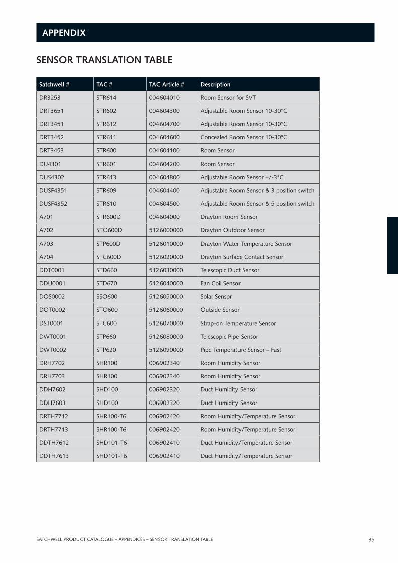
SATCHWEll PrOduCT CATAlOguE – SATCHWEll SIgMA – IAC TOuCH SCrEEN dISPlAy 35
AppENDIx
SENSOR TRANSLATION TABLE
Satchwell # TAC # TAC Article # Description
dr3253 STr614 004604010 room Sensor for SVT
drT3651 STr602 004604300 Adjustable room Sensor 10-30°C
drT3451 STr612 004604700 Adjustable room Sensor 10-30°C
drT3452 STr611 004604600 Concealed room Sensor 10-30°C
drT3453 STr600 004604100 room Sensor
du4301 STr601 004604200 room Sensor
duS4302 STr613 004604800 Adjustable room Sensor +/-3°C
duSF4351 STr609 004604400 Adjustable room Sensor & 3 position switch
duSF4352 STr610 004604500 Adjustable room Sensor & 5 position switch
A701 STr600d 004604000 drayton room Sensor
A702 STO600d 5126000000 drayton Outdoor Sensor
A703 STP600d 5126010000 drayton Water Temperature Sensor
A704 STC600d 5126020000 drayton Surface Contact Sensor
ddT0001 STd660 5126030000 Telescopic duct Sensor
ddu0001 STd670 5126040000 Fan Coil Sensor
dOS0002 SSO600 5126050000 Solar Sensor
dOT0002 STO600 5126060000 Outside Sensor
dST0001 STC600 5126070000 Strap-on Temperature Sensor
dWT0001 STP660 5126080000 Telescopic Pipe Sensor
dWT0002 STP620 5126090000 Pipe Temperature Sensor – Fast
drH7702 SHr100 006902340 room Humidity Sensor
drH7703 SHr100 006902340 room Humidity Sensor
ddH7602 SHd100 006902320 duct Humidity Sensor
ddH7603 SHd100 006902320 duct Humidity Sensor
drTH7712 SHr100-T6 006902420 room Humidity/Temperature Sensor
drTH7713 SHr100-T6 006902420 room Humidity/Temperature Sensor
ddTH7612 SHd101-T6 006902410 duct Humidity/Temperature Sensor
ddTH7613 SHd101-T6 006902410 duct Humidity/Temperature Sensor
SATCHWEll PrOduCT CATAlOguE – APPENdICES – SENSOr TrANSlATION TABlE
SATCHWELLCAT_0408.indd 35 29/4/08 10:41:38
© 2008, TACAll brand names, trademarks and registered trademarks are the property of their respective owners. Information contained within this document is subject to change without notice. All rights reserved.
CAT-SATCHWEll-EuApril 2008
Contact details:
TAC headquartersMalmo, Sweden+46 40 38 68 50
Satchwell helpline+44 (0) 1628 [email protected]
www.tac.com
MicroNetDS 10.xxx
TAC systems and products benefit from over 80 years’
experience in the design and manufacture of control systems
for commercial and industrial buildings.
ISO9001 certification and advanced manufacturing systems
ensure TAC products are built to the highest standards of
quality and reliability. The products are backed by 1st class
after sales support and ongoing research and development
programmes, assuring customers of the long-term security of
their investments.
SATCHWELLCAT_0408.indd 36 29/4/08 10:41:39