satellite and debris characterisation in leo and geo …...satellite and debris characterisation in...
TRANSCRIPT

Satellite and debris characterisation in LEO and GEO using adaptive optics
M. Copeland, F. Bennet, F. Rigaut, C. d’Orgeville and V. KorkiakoskiResearch School of Astronomy and Astrophysics, Australian National University, Canberra, ACT
2611, AustraliaSpace Environment Research Centre (SERC Limited), Mt Stromlo Observatory, Weston Creek,
ACT 2611, Australia
C. SmithEOS Space Systems Pty Ltd, Mt Stromlo Observatory, Weston Creek, ACT 2611, Australia
Space Environment Research Centre (SERC Limited), Mt Stromlo Observatory, Weston Creek,ACT 2611, Australia
ABSTRACT
Ground based optical measurements provide useful information for space situational awareness. We report on thedesign of an adaptive optics (AO) system built by the Research School of Astronomy and Astrophysics at the AustralianNational University. The adaptive optics imaging (AOI) system is built for a 1.8 m telescope at Mount StromloObservatory in Canberra, Australia. AOI uses a 277 actuator deformable mirror (DM) and Shack Hartmann wavefrontsensor operating at up to 2kHz. We have improved imaging quality with custom lenses optimised for a 600 - 950 nmwavelength range. We use an acquisition mode with a 75 arcsecond field of view to assist in locating objects quickly.We have completed the optical and mechanical design of AOI. The system is currently being built and we will integrateit onto the telescope and begin on-sky operating in early 2018.
1 INTRODUCTION
Optical measurements can provide important information for tracking and characterising objects to better understand-ing their behaviour. Satellites and debris in low Earth orbit (LEO) can be tracked with high accuracy using satellitelaser ranging (SLR) and debris laser ranging (DLR) systems. SLR systems can track cooperative targets to millimeteraccuracy [1], while DLR can track debris with precision up to 1 m [2, 3].
Beyond LEO laser ranging techniques become ineffective as the return flux becomes too low to measure. Passivetracking can be used for objects further than LEO by capturing images of objects illuminated by the sun. The positionis measured by centroiding the object in the captured image and using telescope tracking information to determine theposition.
Object position can be measured with high accuracy, however it is difficult to predict where an object will be in thefuture. This is due to the dynamic forces acting on the body such as; gravitational forces, atmospheric effects andsolar radiation pressure. The size, shape and orientation can impact how these parameters affect the orbit [4]. Betterunderstanding of how these parameters impact an object orbit allows for improved orbit predictions to be made whichcan increase the accuracy of collision predictions. With enough warning of a collision action can be taken to movesatellites to avoid a collision and reduce the threat of a Kessler Syndrome [5].
Send correspondence to M. Copeland ([email protected])
Copyright © 2017 Advanced Maui Optical and Space Surveillance Technologies Conference (AMOS) – www.amostech.com

Ground based observation is made difficult due to the atmosphere distorting images and preventing features beingresolved. Much like astronomical applications the effects of the atmosphere can be reduced by using adaptive optics(AO), which will correct the wavefront distortions and allow the full resolution of the telescope to be exploited [6].Applying AO to satellite imaging has been shown to improve image quality and allow features such as solar panelsto be resolved [7]. Rotation of the objects were observed by measuring how the feature location was changing overtime.
2 AOI: ADAPTIVE OPTICS IMAGING SYSTEM
We have developed the Adaptive Optics Imaging (AOI) system for capturing images of satellies and debris in lowEarth orbit (LEO) and geostationary orbit (GEO). The system will operate on a 1.8 m telescope located at Mt. StromloObservatory, Canberra, Australia. AOI will provide AO correction in seeing conditions of 2 arcseconds or better. Theatmospheric conditions at Mt. Stromlo have not been conclusively measured, however a campaign is currently underway to make these measurements [8].
We will operate AOI in two scenarios; using a natural guide star (NGS) or laser guide star (LGS) for wavefrontmeasurement. As the object moves quickly across the sky we cannot use a stellar source as our NGS. Instead we usethe object being imaged as the NGS to obtain the wavefront measurement for the AO system. To do this we must splitthe light between the wavefront sensor and imaging camera.
When using the laser guide star we will create an artificial beacon in the sodium layer of the atmosphere to obtainthe wavefront measurement. A laser guide star will enable us to image fainter objects as more light can be sent to theimaging camera.
2.1 LEO IMAGING
With the 1.8 m telescope and AOI we will resolve objects 50 cm in size at a range of 800 km and imaging wavelengthof 800 nm. This enables us to characterise satellites and debris in LEO by observing the size and shape of the objects.We will be able to resolve specific features such as solar panels or the satellite body. By resolving features of theobject we can obtain a better measurement of the centroid, which will aid in improving orbital predictions as we canunderstand how rotation and external forces may act upon the object.
Fig. 1: Left: Ideal image of an iridium satellite. Right: Simulated image of satellite through AOI. The image is an 50× 50 pixel area of the detector.
Fig. 1 shows a simulation of an iridium satellite as seen through the AO system optics. The left image shows the truthimage of the satellite and the right the image obtained by the AO system through the telescope. The size and shape ofthe satellite body is visible and the two solar panels can be resolved. A resolved image such as Fig. 1 would allow forrotation measurement as the change in solar panel and body position could be measured over time.
Copyright © 2017 Advanced Maui Optical and Space Surveillance Technologies Conference (AMOS) – www.amostech.com

2.2 GEO TRACKING
We will use AOI to obtain high accuracy position measurements of satellites in GEO. We will use stars from the Gaiacatalogue as an astrometric reference to measure the position of a satellite as is passes by the star. The concept ofoperation for tracking in GEO is shown in Fig. 2. We will follow the reference star with the telescope and when thesatellite is within 15 arcseconds we will capture images. We will use centroiding to obtain the position of the satelliteas it passes by the reference star to determine its position.
Fig. 2: GEO imaging operational concept. The satellite will be imaged while it is within 15 arcseconds of the referencestar. The satellite passes within 5 acrseconds of the reference star during the imaging period.
With AOI we can track smaller and fainter objects than a system without AO. The AO system reduces the speckle inour image and concentrates light onto a fewer pixels allowing fainter objects to be detected. AOI will allow us to trackobjects of magnitude 15 or brighter, which is equivalent to objects of 1 m2 or larger in size. We will obtain positionalmeasurements with accuracy of approximately 1 m.
3 OPTICAL DESIGN
We have finalised the optical design of the AO system, with the layout shown in Fig. 3. Light for the telescopeis collimated and travels along a 20 m Coude path to a clean room containing AOI. The parabolic mirror focussesthe beam and it is collimated by two lenses to 24 mm diameter, the deformable mirror (DM) aperture size. Afterreflecting off the DM the beam passed through a dichroic beamsplitter where wavelengths between 450 and 800 nmare transmitted to the wavefront sensor and wavelengths 800 to 950 nm are reflected to the imaging camera.
We selected a 277 actuator DM and Shack Hartmann wavefront sensor operating at 2 kHz. We found that thesespecifications gave the best AO performance in the design conditions of 2 arcsecond seeing or better [9].
Images are captured with a Nuvu Hnu 512 EMCCD camera. This camera has 512 × 512 pixels and will operate atspeeds of up to 60 Hz. We will operate the camera at >30 Hz to reduce the effects of tip-tilt and object rotations.We will also employ lucky imaging techniques to shift and stack to best quality images to improve the final imagingquality.
Imaging performance of the system was improved by using a compound imaging lens consisting of two custom designlenses. We designed these lenses to reduce optical aberrations over a wavelength range of 600 to 950 nm. The customlenses allow us to achieve diffraction limited imaging over the 22 arcsecond field of view of the system. The spotdiagrams produced over wavelengths 800 - 950 nm are shown in Fig. 4.
Copyright © 2017 Advanced Maui Optical and Space Surveillance Technologies Conference (AMOS) – www.amostech.com
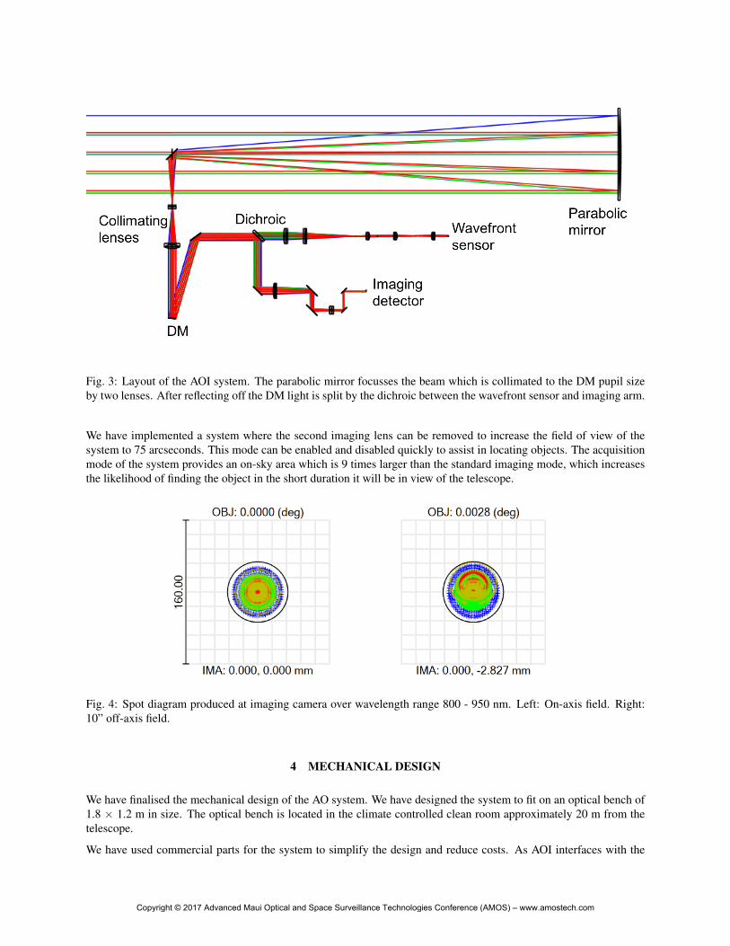
Fig. 3: Layout of the AOI system. The parabolic mirror focusses the beam which is collimated to the DM pupil sizeby two lenses. After reflecting off the DM light is split by the dichroic between the wavefront sensor and imaging arm.
We have implemented a system where the second imaging lens can be removed to increase the field of view of thesystem to 75 arcseconds. This mode can be enabled and disabled quickly to assist in locating objects. The acquisitionmode of the system provides an on-sky area which is 9 times larger than the standard imaging mode, which increasesthe likelihood of finding the object in the short duration it will be in view of the telescope.
Fig. 4: Spot diagram produced at imaging camera over wavelength range 800 - 950 nm. Left: On-axis field. Right:10” off-axis field.
4 MECHANICAL DESIGN
We have finalised the mechanical design of the AO system. We have designed the system to fit on an optical bench of1.8 × 1.2 m in size. The optical bench is located in the climate controlled clean room approximately 20 m from thetelescope.
We have used commercial parts for the system to simplify the design and reduce costs. As AOI interfaces with the
Copyright © 2017 Advanced Maui Optical and Space Surveillance Technologies Conference (AMOS) – www.amostech.com

Fig. 5: Mechanical layout of AOI. Left: Top view of the mechanical layout. Right: Trimetric view of the mechanicallayout
telescope via a Coude path we did not have to design the system to be gravity invariant, therefore commercial partscan provide the appropriate stability.
The mechanical design of the system is shown in Fig. 5. The main components of the AO system (DM, WFS andimaging camera) have been placed on a breadboard which is 600 × 1200 mm in size. The beam expander primary andsecondary mirror mounts are located directly on the optical bench.
We have designed the wavefront sensor to be interchangeable with another AO system, so the same camera can beused on two systems. The wavefront sensor mount includes the OCAM2k EMCCD camera, microlens array, and tworelay lenses. The WFS is mounted kinematically with three points, this mount can be lifted off the bases and movedto another system quickly with little adjustment required.
5 FUTURE DEVELOPMENT
We are currently building the AO system and will be integrating onto the telescope and beginning operations in early2018. We will operate the system NGS mode and characterisation data obtained will be provided to partners in theSpace Environment Research Centre (SERC) for improving orbital prediction models. We will also conduct surveysto identify high area to mass ratio (HAMR) objects which could be used for orbit modification from a ground basedlaser system.
In 2019 we will have a laser guide star facility operational on the telescope. AOI will be upgraded to work with a LGSand we will conduct on-sky operations in LGS mode. The addition of the LGS will enable us to image fainter objectsand we can compare the performance of the system with the NGS mode.
6 CONCLUSION
We have designed an adaptive optics system capable of characterising objects in LEO and tracking satellites in GEO.The AO system features a 277 actuator deformable mirror and Shack Hartmann wavefront sensor operating at 2 kHz.We have improved imaging performance by utilising custom lenses to reduce optical aberrations over a wavelengthrange of 600 - 950 nm. We have implemented a 75 arcsecond field of view to assist in finding targets quickly, andwe then switch to the standard imaging mode. We have completed the mechanical design of the AO system and arecurrently building the system and we will begin operation of the system in early 2018.
Copyright © 2017 Advanced Maui Optical and Space Surveillance Technologies Conference (AMOS) – www.amostech.com

7 ACKNOWLEDGEMENT
The authors would like to acknowledge the support of the Cooperative Research Centre for Space Environment Man-agement (SERC Limited) through the Australian Governments Cooperative Research Centre Programme.
This research is supported by an Australian Government Research Training Program (RTP) Scholarship.
REFERENCES
[1] J. Degnan, “Satellite Laser Ranging: Current Status and Future Prospects,” IEEE Transactions on Geoscience andRemote Sensing, vol. GE-23, no. 4, pp. 398–413, 1985.
[2] G. Kirchner, F. Koidl, F. Friederich, I. Buske, U. Volker, and W. Riede, “Laser measurements to space debris fromGraz SLR station,” Advances in Space Research, vol. 51, pp. 21–24, 2013.
[3] F. Bennet, C. D’Orgeville, Y. Gao, W. Gardhouse, N. Paulin, I. Price, F. Rigaut, I. T. Ritchie, C. H. Smith, K. Uh-lendorf, and Y. Wang, “Adaptive optics for space debris tracking,” in Proceedings of SPIE - The InternationalSociety for Optical Engineering, vol. 9148, p. 91481F, 2014.
[4] C. Fruh, M. Jah, and T. Kelecy, “Coupled Orbit-Attitude Dynamics of High Area-to-Mass Ratio (HAMR) Objects:Influence of Solar Radiation Pressure, Earth’s Shadow and the Visibility in Light Curves,” Celestial Mechanicsand Dynamical Astronomy, vol. 117, no. 4, pp. 385–404, 2013.
[5] D. J. Kessler and B. G. Cour-Palais, “Collision frequency of artificial satellites: The creation of a debris belt,”Journal of Geophysical Research, vol. 83, no. A6, p. 2637, 1978.
[6] J. M. Beckers, “Adaptive optics for astronomy: Principles, Perfomance and Applications,” Annu. Rev. Astron.Astrophys., vol. 31, pp. 13–62, 1993.
[7] F. Bennet, I. Price, F. Rigaut, and M. Copeland, “Satellite imaging with adaptive optics on a 1 m telescope,”Advanced Maui Optical and Space Surveillance Technologies (AMOS) Conference, 2016.
[8] E. Thorn, D. Grosse, F. Rigaut, F. Bennet, V. Korkiakoski, and C. Smith, “Stereo-SCIDAR system for improve-ment of adaptive optics space debris-tracking activities,” in Advanced Maui Optical and Space Surveillance Tech-nologies (AMOS) Conference, 2017.
[9] M. Copeland, F. Bennet, A. Zovaro, F. Riguat, P. Piatrou, and V. Korkiakoski, “Adaptive Optics for Satelliteand Debris Imaging in LEO and GEO,” Advanced Maui Optical and Space Surveillance Technologies (AMOS)Conference, 2016.
Copyright © 2017 Advanced Maui Optical and Space Surveillance Technologies Conference (AMOS) – www.amostech.com