satellite communication
TRANSCRIPT

Syed Absar kazmi (G1220119)
1
INTERNATIONAL ISLAMIC UNIVERSITY MALAYSIA
KULLIYYAH OF ENGINEERING
DEPARTMENT OF ELECTRICAL & COMPUTER ENGINEERING
Course Code: ECE 6233 (Design Project)
Course Title : Satellite Communication
Submission Due: December 12, 2014
Prof Rafiqul Islam
Syed Absar kazmi (G1220119)
0060182391572
1. Estimate the Rain Fade for earth-to-satellite microwave Down links for the following
frequency bands (LP-V, LP-H, CP):
a. C-band (4 GHz)
b. Ku-band (12 GHz)
c. Ka-band (20 GHz)
d. V-band (30 GHz)
2. Make a table and compare the estimated rain fades for above four bands with three different
polarizations.
3. Design and estimate the downlink budget for the above frequency bands by highlighting the
following two parameters:
C/N ratio during clear air
C/N ratio during rain
4. Predict the BER for QPSK modulation and above environmental conditions.
5. For Malaysian Students use the earth station in Kuala Lumpur and MEASAT3 as satellite

Syed Absar kazmi (G1220119)
2
6. For International Students use your capital as earth station and any communication satellite used by
your country.Use all values and prediction procedures proposed by International Telecommunication
Union (ITU-R).
Assume the standard transmit powers and gains for satellite and earth station antennas.
Introduction
In this Assignment, will design and analyze the downlinks and link budget for C-band, Ku
band, Ka-band and V-Band. Rain attenuation for all bands are calculated and compared. The
location of the earth station that we are considering isIslamabad ,Pakistan (33.7167° N,
73.0667° E)
Parameters
Parameters Particulars
Satellite INTELSAT 906
City: Islamabad,Pakistan
Rain Rate for 0.01% of average year, R0.01%: 20 mm/hr
Height above mean sea-level, hs: 560m = .560 km
Isotherm Height, ho: 3 km
Elevation Angle, θ: 50o
Φ 33.71o (Latitude)
Syed Absar kazmi (G1220119)
3
C-band frequency: 4 GHz
Ku-band Frequency: 12 GHz
Ka-band Frequency: 20 GHz
V-band Frequency 30 GHz
Polarization: Horizontal, Vertical and circular
Location 33.7167° N, 73.0667° E
Table .(1)
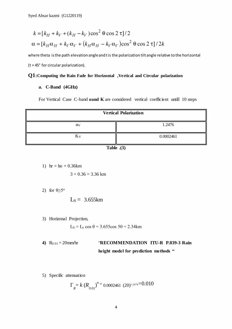
Figure 2: Schematic of Earth-space path parameters
B = rain height, D = Earth-Space Link
Bands Frequencies KH αH KV αV KC αC
C-Band 4 GHz 0.0001071 1.6009 0.0002461 1.2476 0.0001766 1.344
Ku-Band 12 GHz 0.02386 1.1825 0.02455 1.1216 0.024205 1.1512
Ka-Band 20 GHz 0.09164 1.0568 0.09611 0.9847 0.097875 1.0207
V-Band 30 GHz 0.2403 0.9485 0.2291 0.9129 0.2347 0.931124
Table .(2)
Table 1: Coefficients used for estimating the rain attenuation
Table 1 shows the coefficients used for the estimation of rain attenuation for given frequency
bands C-band , Ka-band,Ku-band and V-band.Where as there are two coefficient for each
frequency band which are K and Alpha and for horizontal ,vertical and circular polarization
K and α values has been taken from the “RECOMMENDATION ITU-R P.838-3 Specific
attenuation model for rain for use in prediction methods “ for horizontal and vertical
pollarization they have given from 1-1000 GHz,Infact for circular polarization we need to
calculate the values by given equations
Syed Absar kazmi (G1220119)
4
where theta is the path elevation angle and t is the polarization tilt angle relative to the horizontal
(t = 45° for circular polarization).
Q1:Computing the Rain Fade for Horizontal ,Vertical and Circular polarization
a. C-Band (4GHz)
For Vertical Case C-band αand K are considered vertical coefficient untill 10 steps
Vertical Polarization
αV 1.2476
KV 0.0002461
Table .(3)
1) hr = ho + 0.36km
3 + 0.36 = 3.36 km
2) for θ≥5o
LS = 3.655km
3) Horizonal Projection,
LG = Ls cos θ = 3.655cos 50 = 2.34km
4) R0.01 = 20mm/hr “RECOMMENDATION ITU-R P.839-3 Rain
height model for prediction methods “
5) Specific attenuation
ΓR= k (R
0.01)
α = 0.0002461 (20)1.2476=0.010

Syed Absar kazmi (G1220119)
5
6) Horizontal Reduction factor
r0.01 = 1.46
7) Vertical adjustment factor, V0.01 for 0.01% of the time
ξ = tan-1 ( hr-hs)/LGr0.01= 36.62O
For ξ > θ, LR = 3655m=3.655km
If Φ <36o x = 36- Φ
V0.01 = 1.649
8) The effective path length:
LE = LRV0.01 = 3.655* 1.649
= 6.029 km
9) The predicted attenuation exceeded for 0.01% of an average year is
obtained from
A0.01
= γR
LE
= 0.11925 * 4.5 = 0.53 dB

Syed Absar kazmi (G1220119)
6
By using MATLAB tool , I have atained the attenuation for the given four bands and
three polarization
a. C-band, f = 4GHz
Polarization: Attenuation
Horizontal polarization: 0.048
Vertical polarization: 0.0403
Circular polarization: 0.039
Table .(4)
Table .(4) shows the numerical values of atmospheric attenuation for horizontal,vertical and
circular polarization for C-band downlink only which have some minor variation in
attenuation.
Attenuation
values M-file coding for
attenuatioin

Syed Absar kazmi (G1220119)
7
Ku-Band (12GHz)
Table .(5)
Table .(5) shows the numerical values of atmospheric attenuation for horizontal,vertical and
circular polarization for Ku-band downlink frequency 12GHz only ,which have some minor
variation among three polarizations however it is far more then the C-Band.
b. Ka-Band ( 20GHz)
Polarization: Attenuation
Horizontal polarization: 9.847
Vertical polarization: 8.693
Circular polarization: 9.134
Table .(6)
Table .(6) shows the numerical values of atmospheric attenuation for horizontal,vertical and
circular polarization for Ka-band downlink frequency 20 GHz only .However,it can be
concluded that increase in frequency the attenuation become higher.
c. V-Band ( 30 GHz)
Polarization: Attenuation
Horizontal polarization: 19.622
Vertical polarization: 17.515
Circular polarization: 18.369
Polarization: Attenuation
Horizontal polarization: 3.406
Vertical polarization: 3.063
Circular polarization: 3.197

Syed Absar kazmi (G1220119)
8
Table .(7)
Table .(7) shows the numerical values of atmospheric attenuation for horizontal,vertical and
circular polarization for V-band downlink only 30 GHz.however the values which are
obtained by matlab are the highest attenuation among all bands.Hence ,for counter measure
need high power to over come this fade or thos band is inappropriate for satellite modulation
due to high loss of power.
Question No 2
Make a table and compare the estimated rain fades for above four bands with three
different polarizations.
Frequencies Horizontal
polarization: Vertical
polarization : Circular
polarization
C-Band (4GHz) 0.048 0.0403 0.039
Ku-Band (12GHz) 3.406 3.063 3.197
Ka-Band (20GHz) 9.847 8.693 9.134
V-Band (30 GHz) 19.622 17.515 18.369
Table .(2.1)
Analysis:
The results obtained in this assignment are based on the Intelsat 906 satellite considered
islamabad,pakistan as earth station characteristics whichoperate at Cand Ku-band and
projections are made into higher frequency bands Across all thefrequency bands from C-band
up to V-band, rainfall attenuation, elevation angle, and efective pathlength have been
determined for satellite link. It is noted that the severity of The degradation of the
propagating signal increases with increasing availability. However, the signal degradation
increases with an increase in operating frequency of the satellite link. It can be observed by
the the results of all frequency bands,variation in attenuation is too obvious which has less
impact on C-band as campared to rest of frequency bands.However , if we corelate the
different pollarizations like horizontal,vertical and circular ,we can analyze that horizontal
polarization has the highest attenuation among all frequency bands whereas , vertical with
least attenuation and circular in between them. Furthermore,by maintaining a low fade
marginrequirement for the C-band for all polarizations can only be attributed to its
significantly low local rain rate of 20mm/h. However ,for the higher frequency bands it

Syed Absar kazmi (G1220119)
9
remains in need of higher fade margins as compared to C band which is less prone to
degradation as campared to ku,ka and V-band.
Ultimately , it can be concluded that , its higly recommended to implicate the C-band for all
pollarization as it requires less fade margin for the consolidation of link and vertical
pollarization among all pollarizationn in all frequency band since it got the least attenuation
factor which will lead to enhance the performance. Moreover , since the attenuation factor is
much more than C-band in Ka , Kuand v-band ,therefore enough power is required to cope
the degrading of link to receive the appropriate signal strength.
Recommendation for Ka,Ku and V bands based on gradients
To cope the attenuation attrubutes which have a great impact on performace of link in Ku ,
Kaand v-bands some prerequisite need to accumodated
Power control,The transmitter power is adjusted to compensate for variations in signal
attenuation along the path,Signal Processing and Diversity
Question No 3
Design and estimate the downlink budget for the above frequency bands by highlighting the
following two parameters:
C/N ratio during clear air
C/N ratio during rain
(a) Down link budget for C-band
i. Downlink power budget for C-band Clear Air
Parameters values
Transmit power Pt 13 dBW
Transmiter gain Gt 20 dB
Reciever gain Gr 49.7 dB
Path loss Lp -196.5 dB

Syed Absar kazmi (G1220119)
10
Attenuation loss La -3dB
Other loses Lm -0.7dB
Table .(3.1)
Recieve power Pr = Pt + Gt + Gr – Lp – La – Lm
= 13+ 20 + 49.7 – -196.5 – 3 – 0.7
= -117.5 dBW = 1.77 pW
Down link Noise power budget
Table .(3.2)
Noise power N = -135.5 dBW
Carrier to noise ratio:
(C/N)clear air= Pr – N = -117.5 – (-135.5) = 18 dB
ii. C-band Budget in Rain
Rain attenuation A = 1 dB
G = 10-A/10 = 0.79
Tsky, rain = 270(1-0.79) = 56.7 K
Tsky, rain =T + DT = 56.7 + 110
s =166.7 K = 22.22 dB
Parameters values
Bolts constant K -228.6dBW/K/Hz
Temperature Ts 18.8 dBk
Bandwidth Bn 74.3 dBHz

Syed Absar kazmi (G1220119)
11
Pr (rain) = Pr(clear air) – A = -117.5 dBW – 1 dB = -118.5
dBW
= 1.41 pW
Ts (clear air) = 18.88 dB = 12.76 K
ΔN = 10log (56.7 /12.76) = 6.47dB + 1 (rain atten.)
= 7.4 dB
(C/N)RAIN = 18 (clear air) – 6.47 = 11.53 dB
(b) Down link budget for Ku-band
i. Clear Air
Transmit power Pt 18 dBW
Transmiter gain Gt 31 dB
Reciever gain Gr 46.7 dB
Path loss Lp -205.4 dB
Attenuation loss La -3dB
Other loses Lm -0.8 dB
Table .(3.3)
Pr = Pt + Gt + Gr – Po – Lp – La – Lm
= 18 + 31 + 46.7 – 20.5 – 3 – 0.8
= -113.5 dBW = 4.5 pW
Noise power budget
Parameters values
Bolts constant K -228.6 dBW/K/Hz
Temperature Ts 21.5 dBk
Bandwidth Bn 76.4 dBHz
Table .(3.4)

Syed Absar kazmi (G1220119)
12
N = -130.7 dBW
(C/N)clear air= Pr – N = -113.5 – (-130.7) = 17.2 dB
ii. Ku-band Budget in Rain
A = 7.05 dB
G = 10-A/10 = 0.197
Tsky, rain = 270(1-0.197) = 216.8 K
Tsky, rain = T + DT =216.8 + 10
= 326.8 K = 25 dB
Pr (rain) = Pr(clear air) – A = -113.5 dBW – 7.05 dB
= -120.55 dBW = 0.88pW
Ts (clear air) = 21.5 dB = 140 K
ΔN = 10log (326.8 /140) = 3.68 dB + 7.05 (rain atten.)
= 10.73 dB
(C/N)RAIN = 17.2 (clear air) – 10.73 = 6.47 dB
(c) Down link budget for Ka-band
i. Clear Air
Prameters Values
Transmit power Pt 56.02dBW
Transmiter gain Gt 85.87 dB
Reciever gain Gr 63.82 dB
Path loss Lp -402.5 dB

Syed Absar kazmi (G1220119)
13
Attenuation loss La -3dB
Other loses Lm -0.8 dB
Table .(3.5)
Pr = Pt + Gt + Gr – Po – Lp – La – Lm
= -200.59dBW= 8.7*10^-21 W
Noise power budget
Parameters values
Bolts constant K -228.6 dBW/K/Hz
Temperature Ts 21.5 dBk
Bandwidth Bn 76.4 dBHz
Table .(3.6)
N = -130.7 dBW
(C/N)clear air= Pr – N = -69.89 dB
ii. Ka-band Budget in Rain
A = 10 dB
G = 10-A/10 = 0.1 dB
Tsky, rain = 270(1-0.1) = 243K
Tsky, rain = T + DT =243+ 110
=353 K = 25.47 dB
Pr (rain) = Pr(clear air) – A = -200.59 dBW – 10 dB
= -210.59 dBW = 8.73*10^-22 W
Ts (clear air) = 21.5 dB = 140 K
ΔN = 10log (243 /140) = 2.4dB + 10(rain atten.)
Syed Absar kazmi (G1220119)
14
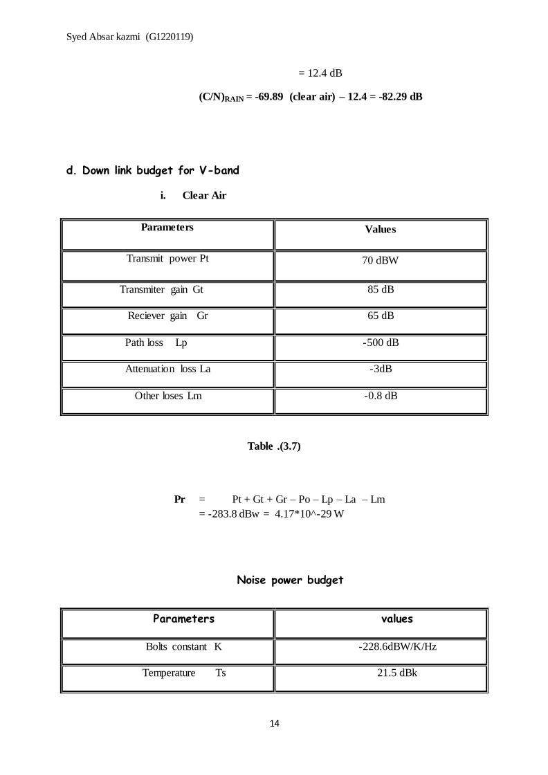
= 12.4 dB
(C/N)RAIN = -69.89 (clear air) – 12.4 = -82.29 dB
d. Down link budget for V-band
i. Clear Air
Parameters Values
Transmit power Pt 70 dBW
Transmiter gain Gt 85 dB
Reciever gain Gr 65 dB
Path loss Lp -500 dB
Attenuation loss La -3dB
Other loses Lm -0.8 dB
Table .(3.7)
Pr = Pt + Gt + Gr – Po – Lp – La – Lm
= -283.8 dBw = 4.17*10^-29 W
Noise power budget
Parameters values
Bolts constant K -228.6dBW/K/Hz
Temperature Ts 21.5 dBk

Syed Absar kazmi (G1220119)
15
Bandwidth Bn 76.4 dBHz
Table .(3.8)
N = -130.7 dBW
(C/N)clear air= -283.8 -130.7 = -153.1 dB
ii. V-band Budget in Rain
A = 15 dB
G = 10-A/10 = 0.03 dB
Tsky, rain = 270(1-0.03) = 261.9 K
Tsky, rain = T + DT =261.9 + 10
=371. 9K = 25.7 dB
Pr (rain) = Pr(clear air) – A = -153.1 dBW – 15 dB= -168.1
dBW
= 1.54*10^-17W
Ts (clear air) = 21.5 dB = 140 K
ΔN = 10log (261.9 /140) = 2.72dB + 15(rain atten.)
= 17.72 dB
(C/N)RAIN = -153.1 (clear air) – 17.72 = -170.82 dB

Syed Absar kazmi (G1220119)
16
Q4: Predict the BER for QPSK modulation and above environmental conditions
QPSK the spectral efficiency is 2 and the and the Eb/N0 =11.4 dB The corresponding BER is
5*10^-8
The environmental conditions:
Readings obtained from the above graph
(a) - C-Band
CNR Value corresponding BER
Syed Absar kazmi (G1220119)
17
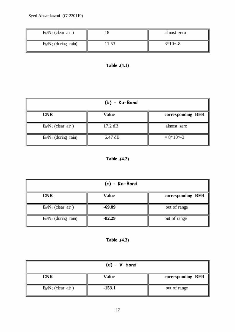
Eb/N0 (clear air ) 18 almost zero
Eb/N0 (during rain) 11.53 3*10^-8
Table .(4.1)
(b) - Ku-Band
CNR Value corresponding BER
Eb/N0 (clear air ) 17.2 dB almost zero
Eb/N0 (during rain) 6.47 dB = 8*10^-3
Table .(4.2)
(c) - Ka-Band
CNR Value corresponding BER
Eb/N0 (clear air ) -69.89 out of range
Eb/N0 (during rain) -82.29 out of range
Table .(4.3)
(d) - V-band
CNR Value corresponding BER
Eb/N0 (clear air ) -153.1 out of range

Syed Absar kazmi (G1220119)
18
Eb/N0 (during rain) -170.82 out of range
Table .(4.4)
MATLAB CODE
%STEP 1:DEFINING THE PARAMETERS
hs=0.56; %the altitude of the ground station above sea level,
in km
theta=0.2778.*pi; %elevation angle
ho=3; %in km
fc=4; %C-Band
fku=12; %Ku-Band
fka=20; %Ka-Band
fv=30; %V-band
zeta=33.71 ; %the latitude of the ground station inDegreeN or S
tc=45; %the polarization tilt angle with respect to horizontal,
in degree
R=20; %from ITU-R recommendation 2012
p=[1 0.7 0.3 0.1 0.07 0.03 0.01 0.007 0.003 0.001]; %percentage
%STEP 2:DETERMINE THE RAIN HEIGHT AT THE GROUND STATION OF REGION
hR=(ho+0.36); %in km
%STEP3: CALCULATE THE SLANT-PATH LENGHT AND HORIZONTAL PROJECTION

Syed Absar kazmi (G1220119)
19
Ls=(hR-hs)./sin(theta); %the slant-path lenght
Lg=Ls.*cos(theta); %the horizontal projection
%STEP 4:CALCULATE THE SPECIFIC ATTENUATION coefficients
kcv=0.0002461; %k for VERTICAL IN C-BAND
kch=0.0001071; %k for HORIZONTAL IN C-BAND
acv=1.2476; %a for VERTICAL IN C-BAND
ach=1.6009; %a for HORIZONTAL IN C-BAND
kkuv=0.02455; %k for VERTICAL IN Ku-BAND
kkuh=0.02386; %k for HORIZONTAL IN Ku-BAND
akuv=1.1216; %a for VERTICAL IN Ku-BAND
akuh=1.1825; %a for HORIZONTAL IN Ku-BAND
kkav=0.09611; %k for VERTICAL IN Ka-BAND
kkah=0.09164; %k for HORIZONTAL IN Ka-BAND
akav=0.9847; %a for VERTICAL IN Ka-BAND
akah=1.0586; %a for HORIZONTAL IN Ka-BAND
kvv=0.2291; %k for VERTICAL IN V-BAND
kvh=0.2403; %k for HORIZONTAL IN V-BAND
avv=0.9129; %a for VERTICAL IN V-BAND
avh=0.9485; %a for HORIZONTAL IN V-BAND
%determine value for k and a in cicular for c-band,ku-band,ka-band
and v-band
kcc=(kch+kcv+((kch-kcv).*cos(theta).*cos(theta).*cos(2.*tc)))./(2);
%k for CIRCULAR IN C-BAND
acc=(kch.*ach+kcv.*acv+(kch.*ach-
kcv.*acv).*cos(theta).*cos(theta).*cos(2.*tc))./(2.*kcc);

Syed Absar kazmi (G1220119)
20
%a for CIRCULAR IN C-BAND
kkuc=(kkuh+kkuv+((kkuh-
kkuv).*cos(theta).*cos(theta).*cos(2.*tc)))./(2);
%k for CIRCULAR IN Ku-BAND
akuc=(kkuh.*akuh+kkuv.*akuv+(kkuh.*akuh-
kkuv.*akuv).*cos(theta).*cos(theta).*cos(2.*tc))./(2.*kkuc); %a
for CIRCULAR IN kU-BAND
kkac=(kkah+kkav+((kkah-
kkav).*cos(theta).*cos(theta).*cos(2.*tc)))./(2);
%k for CIRCULAR IN Ka-BAND
akac=(kkah.*akah+kkav.*akav+(kkah.*akah-
kkav.*akav).*cos(theta).*cos(theta).*cos(2.*tc))./(2.*kkac); %a
for CIRCULAR IN Ka-BAND
kvc=(kvh+kvv+((kvh-kvv).*cos(theta).*cos(theta).*cos(2.*tc)))./(2);
%k for CIRCULAR IN V-BAND
avc=(kvh.*avh+kvv.*avv+(kvh.*avh-
kvv.*avv).*cos(theta).*cos(theta).*cos(2.*tc))./(2.*kvc);
%a for CIRCULAR IN V-BAND
%STEP 5:CALCULATE THE SPECIFIC ATTENUATION COEFFICIENTS
Ycv=kcv.*(R.^acv); %YR for VERTICAL IN C-BAND
Ych=kch.*(R.^ach); %YR for HORIZONTAL IN C-BAND
Ycc=kcc.*(R.^acc); %YR for CIRCULAR IN C-BAND
Ykuv=kkuv.*(R.^akuv); %YR for VERTICAL IN Ku-BAND
Ykuh=kkuh.*(R.^akuh); %YR for HORIZONTAL IN Ku-BAND
Ykuc=kkuc.*(R.^akuc); %YR for CIRCULAR IN Ku-BAND
Ykav=kkav.*(R.^akav); %YR for VERTICAL IN Ka-BAND
Ykah=kkah.*(R.^akah); %YR for HORIZONTAL IN ka-BAND
Ykac=kkac.*(R.^akac); %YR for CIRCULAR IN Ka-BAND
Yvv=kvv.*(R.^avv); %YR for VERTICAL IN v-BAND
Yvh=kvh.*(R.^avh); %YR for HORIZONTAL IN v-BAND
Yvc=kvc.*(R.^avc); %YR for CIRCULAR IN v-BAND
Syed Absar kazmi (G1220119)
21
%STEP 6: CALCULATE THE HORIZONTAL REDUCTION FACTOR
rcv=1./(1+0.78.*(sqrt((Lg.*Ycv)./fc))-0.38.*(1-exp(-2.*Lg)));
%r0.01 for VERTICAL IN C-BAND
rch=1./(1+0.78.*(sqrt((Lg.*Ych)./fc))-0.38.*(1-exp(-2.*Lg)));
%r0.01 for HORIZONTAL IN C-BAND
rcc=1./(1+0.78.*(sqrt((Lg.*Ycc)./fc))-0.38.*(1-exp(-2.*Lg)));
%r0.01 for CIRCULAR IN C-BAND
rkuv=1./(1+0.78.*(sqrt((Lg.*Ykuv)./fku))-0.38.*(1-exp(-2.*Lg)));
%r0.01 for VERTICAL IN Ku-BAND
rkuh=1./(1+0.78.*(sqrt((Lg.*Ykuh)./fku))-0.38.*(1-exp(-2.*Lg)));
%r0.01 for HORIZONTAL IN Ku-BAND
rkuc=1./(1+0.78.*(sqrt((Lg.*Ykuc)./fku))-0.38.*(1-exp(-2.*Lg)));
%r0.01 for CIRCULAR IN Ku-BAND
rkav=1./(1+0.78.*(sqrt((Lg.*Ykav)./fka))-0.38.*(1-exp(-2.*Lg)));
%r0.01 for VERTICAL IN Ka-BAND
rkah=1./(1+0.78.*(sqrt((Lg.*Ykah)./fka))-0.38.*(1-exp(-2.*Lg)));
%r0.01 for HORIZONTAL IN Ka-BAND
rkac=1./(1+0.78.*(sqrt((Lg.*Ykac)./fka))-0.38.*(1-exp(-2.*Lg)));
%r0.01 for CIRCULAR IN Ka-BAND
rvv=1./(1+0.78.*(sqrt((Lg.*Yvv)./fv))-0.38.*(1-exp(-2.*Lg)));
%r0.01 for VERTICAL IN V-BAND
rvh=1./(1+0.78.*(sqrt((Lg.*Yvh)./fv))-0.38.*(1-exp(-2.*Lg)));
%r0.01 for HORIZONTAL IN V-BAND
rvc=1./(1+0.78.*(sqrt((Lg.*Yvc)./fv))-0.38.*(1-exp(-2.*Lg)));
%r0.01 for CIRCULAR IN V-BAND
%STEP 7: CALCULATE THE VALUE OF ZETA
zcv=atand((hR-hs)./(Lg.*rcv)); %z for VERTICAL IN C-BAND
zch=atand((hR-hs)./(Lg.*rch)); %z for HORIZONTAL IN C-BAND
zcc=atand((hR-hs)./(Lg.*rcc)); %z for CIRCULAR IN C-BAND
zkuv=atand((hR-hs)./(Lg.*rkuv)); %z for VERTICAL IN Ku-BAND
zkuh=atand((hR-hs)./(Lg.*rkuh)); %z for HORIZONTAL IN Ku-BAND
Syed Absar kazmi (G1220119)
22
zkuc=atand((hR-hs)./(Lg.*rkuc)); %z for CIRCULAR IN Ku-BAND
zkav=atand((hR-hs)./(Lg.*rkav)); %z for VERTICAL IN Ka-BAND
zkah=atand((hR-hs)./(Lg.*rkah)); %z for HORIZONTAL IN Ka-BAND
zkac=atand((hR-hs)./(Lg.*rkac)); %z for CIRCULAR IN Ka-BAND
zvv=atand((hR-hs)./(Lg.*rvv)); %z for VERTICAL IN V-BAND
zvh=atand((hR-hs)./(Lg.*rvh)); %z for HORIZONTAL IN V-BAND
zvc=atand((hR-hs)./(Lg.*rvc)); %z for CIRCULAR IN V-BAND
%STEP 8: CALCULATE THE VALUE OF X
X=36-zeta;
%STEP 9: CALCULATE THE LR
Lrcv=(hR-hs)./(sin(theta)); %Lr0.01 for VERTICAL IN C-BAND
Lrch=(hR-hs)./(sin(theta)); %Lr0.01 for HORIZONTAL IN C-BAND
Lrcc=(hR-hs)./(sin(theta)); %Lr0.01 for CIRCULAR IN C-BAND
Lrkuv=(Lg.*rkuv)./(cos(theta)); %Lr0.01 for VERTICAL IN Ku-BAND
Lrkuh=(Lg.*rkuh)./(cos(theta)); %Lr0.01 for HORIZONTAL IN Ku-
BAND
Lrkuc=(Lg.*rkuc)./(cos(theta)); %Lr0.01 for CIRCULAR IN Ku-BAND
Lrkav=(Lg.*rkav)./(cos(theta)); %Lr0.01 for VERTICAL IN Ka-BAND
Lrkah=(Lg.*rkah)./(cos(theta)); %Lr0.01 for HORIZONTAL IN Ka-
BAND
Lrkac=(Lg.*rkac)./(cos(theta)); %Lr0.01 for CIRCULAR IN Ka-BAND
Lrvv=(Lg.*rvv)./(cos(theta)); %Lr0.01 for VERTICAL IN V-BAND
Lrvh=(Lg.*rvh)./(cos(theta)); %Lr0.01 for HORIZONTAL IN V-BAND
Lrvc=(Lg.*rvc)./(cos(theta)); %Lr0.01 for CIRCULAR IN V-BAND
%STEP 7: CALCULATE THE VERTICAL ADJUSTMENT FACTOR

Syed Absar kazmi (G1220119)
23
vcv=1./(1+sqrt(sin(theta)).*(31.*(1-exp(-
77.4./(1+X))).*(sqrt(Lrcv.*Ycv)./(fc.*fc))-0.45)); %V0.01
for VERTICAL IN C-BAND
vch=1./(1+sqrt(sin(theta)).*(31.*(1-exp(-
77.4./(1+X))).*(sqrt(Lrch.*Ych)./(fc.*fc))-0.45)); %V0.01
for HORIZONTAL IN C-BAND
vcc=1./(1+sqrt(sin(theta)).*(31.*(1-exp(-
77.4./(1+X))).*(sqrt(Lrcc.*Ycc)./(fc.*fc))-0.45)); %V0.01
for CIRCULAR IN C-BAND
vkuv=1./(1+sqrt(sin(theta)).*(31.*(1-exp(-
77.4./(1+X))).*(sqrt(Lrkuv.*Ykuv)./(fku.*fku))-0.45)); %V0.01 for
VERTICAL IN Ku-BAND
vkuh=1./(1+sqrt(sin(theta)).*(31.*(1-exp(-
77.4./(1+X))).*(sqrt(Lrkuh.*Ykuh)./(fku.*fku))-0.45)); %V0.01 for
HORIZONTAL IN Ku-BAND
vkuc=1./(1+sqrt(sin(theta)).*(31.*(1-exp(-
77.4./(1+X))).*(sqrt(Lrkuc.*Ykuc)./(fku.*fku))-0.45)); %V0.01 for
CIRCULAR IN Ku-BAND
vkav=1./(1+sqrt(sin(theta)).*(31.*(1-exp(-
77.4./(1+X))).*(sqrt(Lrkav.*Ykav)./(fka.*fka))-0.45)); %V0.01 for
VERTICAL IN Ka-BAND
vkah=1./(1+sqrt(sin(theta)).*(31.*(1-exp(-
77.4./(1+X))).*(sqrt(Lrkah.*Ykah)./(fka.*fka))-0.45)); %V0.01 for
HORIZONTAL IN Ka-BAND
vkac=1./(1+sqrt(sin(theta)).*(31.*(1-exp(-
77.4./(1+X))).*(sqrt(Lrkac.*Ykac)./(fka.*fka))-0.45)); %V0.01 for
CIRCULAR IN Ka-BAND
vvv=1./(1+sqrt(sin(theta)).*(31.*(1-exp(-
77.4./(1+X))).*(sqrt(Lrvv.*Yvv)./(fv.*fv))-0.45)); %V0.01
for VERTICAL IN V-BAND
vvh=1./(1+sqrt(sin(theta)).*(31.*(1-exp(-
77.4./(1+X))).*(sqrt(Lrvh.*Yvh)./(fv.*fv))-0.45)); %V0.01
for HORIZONTAL IN V-BAND
vvc=1./(1+sqrt(sin(theta)).*(31.*(1-exp(-
77.4./(1+X))).*(sqrt(Lrvc.*Yvc)./(fv.*fv))-0.45)); %V0.01
for CIRCULAR IN V-BAND
%STEP 8: DETERMINE THE EFFECTIVE PATH LENGTH

Syed Absar kazmi (G1220119)
24
Lecv=Lrcv.*vcv; %lE for VERTICAL IN C-BAND
Lech=Lrch.*vch; %LE for HORIZONTAL IN C-BAND
Lecc=Lrcc.*vcc; %LE for CIRCULAR IN C-BAND
Lekuv=Lrkuv.*vkuv; %LE for VERTICAL IN Ku-BAND
Lekuh=Lrkuh.*vkuh; %LE for HORIZONTAL IN Ku-BAND
Lekuc=Lrkuc.*vkuc; %LE for CIRCULAR IN Ku-BAND
Lekav=Lrkav.*vkav; %LE for VERTICAL IN Ka-BAND
Lekah=Lrkah.*vkah; %LE for HORIZONTAL IN Ka-BAND
Lekac=Lrkac.*vkac; %LE for CIRCULAR IN Ka-BAND
Levv=Lrvv.*vvv; %LE for VERTICAL IN V-BAND
Levh=Lrvh.*vvh; %LE for HORIZONTAL IN V-BAND
Levc=Lrvc.*vvc; %LE for CIRCULAR IN V-BAND
%STEP 9:CALCULATE THE ATTENUATION EXCEED FOR 0.01% OF AN AVERAGE YEAR
Acv=Ycv.*Lecv; %A0.01 for VERTICAL IN C-BAND
Ach=Ych.*Lech; %A0.01 for HORIZONTAL IN C-BAND
Acc=Ycc.*Lecc; %A0.01 for CIRCULAR IN C-BAND
Akuv=Ykuv.*Lekuv; %A0.01 for VERTICAL IN Ku-BAND
Akuh=Ykuh.*Lekuh; %A0.01 for HORIZONTAL IN Ku-BAND
Akuc=Ykuc.*Lekuc; %A0.01 for CIRCULAR IN Ku-BAND
Akav=Ykav.*Lekav; %A0.01 for VERTICAL IN Ka-BAND
Akah=Ykah.*Lekah; %A0.01 for HORIZONTAL IN Ka-BAND
Akac=Ykac.*Lekac; %A0.01 for CIRCULAR IN Ka-BAND
Avv=Yvv.*Levv; %A0.01 for VERTICAL IN V-BAND
Avh=Yvh.*Levh; %A0.01 for HORIZONTAL IN V-BAND
Avc=Yvc.*Levc; %A0.01 for CIRCULAR IN V-BAND

Syed Absar kazmi (G1220119)
25
References
1)-Estimation of Rain Attenuation at C, Ka, Ku and V Bands forSatellite Links in South Africa
2) Satellite Link Design (chapter 4)
3) BER vs CNR notes