saturn - charley's greenhouse 17979 state route 536 • mount vernon, wa 98273-3269 ph. (800)...
TRANSCRIPT

Saturn
17979 State Route 536 • Mount Vernon, WA 98273-3269 Ph. (800) 322-4707 • Fax (360) 873-8264
charleysgreenhouse.com
These revised instructions replace the original instructions provided in the kit.
English Garden VITAVIA 8' x 8' 8' x 10' 8' x 12' 8' x 14' (6700) (8300) (9900) (11500)
12-22-14

Assembly instructionsDE
FR
NL
Montageanleitung
Notice de Montage
Montage Instructies
DA
SV
NO
Montagevejledning
Monteringsanvisning
Montasjeveiledning
EN
DIANA / SATURN5000, 6700, 8300, 9900, 11500
006.01.1212 1

2 006.01.1212
ItemNo. Part Sect.
Ref.Sizemm
Quantity per5000 6700 8300 9900 11500
1001 1-6 M6 x 12 184 211 228 256 272
1002 1-6 M6 187 214 231 259 275
1003 5 3.5 x 16 32 32 32 32 32
1004 5 M4 x 16 4 4 4 4 4
1005 4A M6 x 40 2 2 2 2 2
1006 6 3.5 x 6 6 12 12 24 24
1007 5 M4 4 4 4 4 4
1009 5 Ø8/4 4 4 4 4 4
1010 4A 32 2 2 2 2 2
1011 7 70 306 358 414 462 518
1012 7 11 87 105 125 141 161
1014 5 20 4 4 4 4 4
1015 5 Ø22 4 4 4 4 4
1017 4B 46 4 4 4 4 4
1019 6 15 1 2 2 4 4
1020 7
8000093000
105000117000130000
1----
-1---
--1--
---1-
----1
1032 1 1214 4 6 8 10 12
1059 5 621 2 2 2 2 2
1060 5 621 2 2 2 2 2
1061 5 621 4 4 4 4 4
ItemNo. Part Sect.
Ref.Sizemm
Quantity per5000 6700 8300 9900 11500
1062 5 613 2 2 2 2 2
1063 6 635 1 2 2 4 4
1064 6 602 1 2 2 4 4
1065 6 520 2 4 4 8 8
1066 6 602 1 2 2 4 4
1067 6 295 1 2 2 4 4
1092 4A 120 4 4 4 4 4
1111 5 37.5 2 2 2 2 2
1112 5 7.4 2 2 2 2 2
1113 5 25 2 2 2 2 2
1500 5 M6 x 5 2 2 2 2 2
1515 5 M6 2 2 2 2 2
2001 5L M6 x 12 1 1 1 1 1
2005 5R 100 1 1 1 1 1
2006 5R 10 2 2 2 2 2
2016 6 40 2 4 4 8 8
2022202320242025
1A & 21B1B1B
2484310637284350
1---
3---
12--
1-2-
1--2
2046 3 2484 1 1 1 1 1
2048 3 1318 1 1 1 1 1
2050
20514A
2484
3106
-
-
1
-
-
1
-
-
-
-
2

3006.01.1212
ItemNo. Part Sect.
Ref.Sizemm
Quantity per5000 6700 8300 9900 11500
2052
20534A
3728
4350
-
-
-
-
-
-
1
-
-
1
2054 2 1318 1 1 1 1 1
2057 4B 1184.5 2 3 4 5 6
2089
20903 619
1
1
1
1
1
1
1
1
1
1
2091 23 175 2 2 2 2 2
2092 13 37 6 2 6 6 6
2093 1A2 56 1 3 1 1 1
2094 3 426 1 1 1 1 1
2100 23 425 2 2 2 2 2
5001 3 33 1 1 1 1 1
5002 3 33 1 1 1 1 1
5012 7 10 14 14 14 14 14
5021 5 1991 2 2 2 2 2
5022 1A 1862 2 - - - -
50275028502950305031
1A1A1B1B1B
18622484310637284350
2----
-2---
--2--
---2-
----2
5034 23 1214 4 4 4 4 4
5035 23 1884 2 2 2 2 2
5036 23 1884 2 2 2 2 2
5039 2 2476 1 1 1 1 1
5041 23 2030 2 2 2 2 2
ItemNo. Part Sect.
Ref.Sizemm
Quantity per5000 6700 8300 9900 11500
5042 23 2030 2 2 2 2 2
5043 4A 750 2 2 2 2 2
5047 3 1270 2 2 2 2 2
5049 1A4B 1304 8 4 4 4 4
5050 4A 1862 1 - - - -
5055 4B 1861 4 6 8 10 12
5058 5 1991 2 2 2 2 2
50625063506450655066
4B
18542476309837204342
2----
-2---
--2--
---2-
----2
5075
50763 1304
1
1
1
1
1
1
1
1
1
1
5090 7 610 x 610 6 8 10 12 14
5091 1-3 178 8 8 8 8 8
5095 12 1681 2 6 6 6 6
5096 3 619 1 1 1 1 1
5097 3 619 1 1 1 1 1
5098 5R 1991 1 1 1 1 1
5099 5L 1991 1 1 1 1 1
5101 2 2030 1 1 1 1 1
6060 4A Ø12/6 2 2 2 2 2
3

4
(continued on next page)
Safety Warning 1. PLEASE READ THESE INSTRUCTIONS CAREFULLY AND COMPLETELY BEFORE ASSEMBLING YOUR GREENHOUSE.
2. Sharp edges and corners can cause injury. Always wear protective glasses, gloves, shoes and headgear when handling the aluminum profiles, glass and polycarbonate sheets. Broken glass is a safety hazard – always clear up immediately and dispose of with care.
3. The product you have purchased is intended only for the growing of plants and should only be used for this purpose. When used for other purposes we will take no responsibility.
4. It is recommended that this greenhouse is assembled by two people.
5. Should you encounter difficulties construct- ing this house, or in positioning the glass or polycarbonate sheets, please contact your retailer – do not use force!
6. The greenhouse must be well anchored.
Assembly Instructions Site Selection Try to select a sunny location, sheltered from the wind as much as possible.
Important Before assembling your new greenhouse, please check that all parts in the provided list are included. Please take each bundle out of the packaging in order to identify the parts better.
It is important that the opened bundles do not get mixed with one another.
If something is missing please contact your retailer.
Necessary Tools Screwdrivers (Flat-Head and Phillips), 10 mm spanner, box wrench, or nut driver. Also recom-mended to have on hand: caulking gun, ladder, razor blade cutter, measuring tape, level to check foundation.
Maintenance The greenhouse should be thoroughly washed with a gentle detergent occasionally. Please check that the detergent used does not react aggressively with aluminum, polycarbonate, or the glass fixing clips. Ensure that the upper and lower door tracks are cleaned regularly to avoid a build up of debris.
0.0 Base Important! The base must be exactly square and level. A zinc-coated steel base is available as an accessory for all greenhouse models.
(Attention! Only when the greenhouse has to be located in a very windy and unprotected location: Drill through both the sill at the base of the greenhouse and the steel base, and connect them with nuts and bolts. Be sure to position the bolts outside of the glass location.)
If you would rather construct your own lumber, stone, or concrete foundation, please follow the dimensions specified in diagram 0.
Treated wooden boards at least 3/4" high and not more than 1-1/4" wide should be positioned between the stone/concrete foundation and the aluminum frame, and connected to the founda-tion with anchor bolts at least 4" long (not pro-vided).
Foundations must extend down below the frost level for a glass greenhouse.
SATURN 8' x 8' (6700), 8' x 10' (8300), 8' x 12' (9900), 8' x 14' (11500)
csy update 10-6-14

5
All diagrams are shown from the inside of the house, with the exception of those enclosed in a double frame, indicating an outside view.
1. Side Walls Lay all of the parts on the floor and connect them loosely.
For Saturn (Diana) – At this stage, it is neces-sary with each outside vertical aluminum bar (1032) to include an extra bolt in the track. This bolt is required to connect the cross braces (5095), see 1.2.
Loosely connect the corner plate (5091) (1.1).
In step 4 the corner plate bolts must also be connected to the gable ends.
2. Rear Gable End Lay all of the parts on the floor and connect them loosely. Leave 1/16" gap between the curved rib and the corner post (5034) (2.3).
Include two extra bolts in the vertical bars (5041 and 5042) to later connect the cross brace and diagonal braces (2.2 and 2.6). In the center verti-cal bar (5101), include only one extra bolt.
3. Door Gable End Lay all of the parts on the floor and connect them loosely.
The door track (5047) will be connected to the horizontal bar (2048) (3.12). Connect these loosely from the outside with three nuts and bolts.
As in Step 2, include two extra bolts in both vertical bars (5041 and 5042) (3.3).
Install horizontal bars 5096, 5097, 2089, 2090 (3.3). Install diagonal braces 5075 and 5076
(3.9). Install reinforcing bar 2094 (3.6, 3.7).
Connect parts 5001 and 5002, as shown in 3.10 and 3.11, with a nut and bolt.
4A. Connecting the separate Wall Frames See pages 12 and 13 for additional instruc-tions for 4AA. Connecting the Side Walls to the End Walls, and 4AB. Installing the Gutter.
Bolt the side walls to the end walls (4.1, 4.2, and 4.3.)
Install the ridge beam on the gable ends (4.4, 4.5).
Connect the door track supports (5043) to the door track (5047) and to the gable end, using washer (6060), bolt (1005), and spacer (1010) (4.6 and 4.13).
4B. Assemble the Roof Connect the roof glazing bars (5055) between the eaves (4.7) and the ridge bar (4.8).
Insert extra bolts into each glazing bar depen-ding on which greenhouse you have bought. The number is indicated in a circle on each bar and to be read beginning from both ends.
The roof braces (2057) (4.9) and the cross braces (5049) (4.11, 4.12, 4.13) can now be connected.
Now position your greenhouse on the prepared base/foundation and connect loosely. Adjust the greenhouse until it is completely square and tighten all bolts firmly. Do not overtighten. Too much tightening can break the aluminum bolts.
Press the end protectors (1017) onto the gutter ends (4.10).
(continued on next page)
csy update 10-6-14

6
5. Door Attention: Do not stand the assembled door on the door gliders (1014) to avoid damaging them.
Push the door gliders (1014) onto both ends of door bar (1060) (5.1).
Assemble the door as shown in diagram 5.
Connect door rollers (1015) to the door top bar (1062) using bolt (1004), washer (1009) and nut (1007) (5.4).
Bolt the door top bar (1062) to upper frame bar (1059) (5.3) and slide the door seal (5021) into the outside side bar (5058) (5.5). Slide bolts (1500) into the bottom of the bolt channel to hold brush seals (5021), and fit it in place using nut (1515) (5.6). Ensure that for the inside side bar, the part 5098 is used on the right in 5R and part 5099 in the left in 5L.
Connect the door locking tabs (1111, 1112, 1113) as shown. Connect bolt (2001) at the join between both (5047) as shown (5L).
Loosen the door track supports (5043).
The door rollers can now be slid into door track (5047) (5.7). Ensure that the door gliders are also running on the bottom track (5.8).
Once the doors are correctly in place, connect a nut and bolt into both ends of door track (5047) as door stoppers.
Adjust the door so that it moves freely by moving the door up in the connector slots in 1059.
TIP: To permanently hold the door top bar (1062) in the correct position with upper frame bar (1059), drill through both and secure with 2 small screws (not included).
6. Roof Vents Connect the side bars (1065) and the top bar (1064). For glass glazing, see (6.1). For 4 mm polycarbonate glazing, see (6.2).
Place the bolts to connect the bottom bar (1066) in the prepared holes, and then slide the glazing into the tracks in the side bars (1065) (6.3).
Now connect bottom bar (1066), and ensure that the window is totally square before tight-ening all bolts.
Position the window in the ridge bar at one end (6.4) and (6.5) and slide it to the required posi-tion (6.6).
Connect the window sill (1063) with the extra bolts in the roof glazing bars (6.7).
Install automatic vent opener (optional) if ordered separately. For manual vent control, bolt the window opener (1067) to the bottom bar (1066) using screws (1006) (6.8). Connect both window pins (2016) onto the window sill (1063) using screws (1006) (6.8).
Place the plastic cap (1019) over the end of the window opener (1067).
7. Glazing (Glass or Polycarbonate) Please note the already mentioned safety pre-cautions.
Press the glazing seals (1020) onto the alumi-num profiles (7.2) and cut to length.
On the roof, begin by positioning the glazing at the ridge and fix in place using the glazing spring clips (1011) (7.1).
For glass, use method 7A. The lower pane should slide under the pane directly above it with the overlap glazing clips (1012) between the panes (7.3).
(continued on next page)
csy update 10-6-14

7
Install the acrylic eave pane using the bendable aluminum clips (5012) (7.4). Hook clips over the acrylic panel and bend the panel to slip under-neath the glass pane above (#3). Now bend the aluminum clips up (7.4) to hold the glass in place. Install the spring clips (7.1). If difficulties arise in placing the last pane, check that those above have not slipped down.
On the sides begin glazing from the bottom.
When glazing the front or back, fit part 5012 as shown on pane 1 and bend it up to fix upper panes (7.4).
It is possible to replace any glass pane 1 with a louver window, except where there is a diagonal brace. (See recommended locations on drawing.) The louver window is not included.
If you’ve chosen insulating polycarbonate sheets instead of glass panes for your glazing, see the instructions for TwinWall glazing.
Finishing
If desired, it is possible to seal the greenhouse at the edges using silicon. Silicon is not included.
Place the warning label inside the greenhouse.
A full range of greenhouse accessories, to help you make the most of this product, is available from Charley’s Greenhouse & Garden.
charleysgreenhouse.com
1-800-322-4707
Safety Notice In the event of high wind conditions, close the door and all vents.
In the event of heavy snowfall, clear the roof of the greenhouse or take suitable measures to support the roof. Heat the greenhouse to 35° F in winter to keep snow from building up pressure
csy update 10-6-14
NOTES: ____________________________________________________
____________________________________________________
____________________________________________________
____________________________________________________
____________________________________________________
____________________________________________________
____________________________________________________
____________________________________________________
____________________________________________________
____________________________________________________
____________________________________________________
____________________________________________________
____________________________________________________
____________________________________________________
against the walls.
Comments For the complete protection of your new green-house, we advise you to include it in your home insurance. Please take note of possible building code rules relating to the positioning of green-houses.
Please attach the included greenhouse model label on the door bar (1062) after assembling this product. This information is important in the event that replacement parts are later re-quired.
Keep these Assembly Instructions in a safe place, for future reference!
Our policy is one of continuous improvement and we reserve the right to change the specifi-cations without prior notice.

0
006.01.1212
B
A
X = X
6700 8' x 8'
8300 8' x 10'
9900 8' x 12'
11500 8' x 14'
A 2544 mm 100-1/8"
3166 mm 124-1/2"
3788 mm 149-1/8"
4410 mm 173-1/2"
B 2544 mm 100-1/8"
2544 mm 100-1/8"
2544 mm 100-1/8"
2544 mm 100-1/8"
Foundation Sizes
1-1/4"
1-1/4"
1-1/4" wide x 3/4" to 1" thick
Saturn
8

1A
006.01.1212
5000 6700
1001
14x 2 17x 2
1002
14x 2 17x 2
1032
2x 2 3x 2
2022
- 1x 2
2092
2x 2 -
2093
- 1x 2
5022
1x 2 -
5027 50281x 2 1x 2
5049
2x 2 -
5091
2x 2 2x 2
5095
- 2x 2
1.1
1.2
6700 2x
1.61 61A.51A 51.31 3
5095
5028
1032
2022
5091
5095
1032
2022/5022
1032
1032
2022/5022
1.2 1.3
1.6
2022
5095 5095
1032
2093
1A.5
50915049/5095
5027/5028
5049
1032
5022
1.4
2092
Saturn
8' x 8'
9 outside view

1B
006.01.1212
11500 2x
83002x
5091
5031
5030
5029
103220255095
99002x
5091
50915091
1032
1032
5095
5095
2024
2023
1.1
5095
10321032
1032
1.2 1.3
1B.5
50915095
5029/5030/5031
2023/2024/2025
8300 9900 11500
1001
20x 2 22x 2 24x 2
1002
20x 2 22x 2 24x 2
1032
4x 2 5x 2 6x 2
2023 2024 20251x 2 1x 2 1x 2
2092
2x 2 2x 2 2x 2
5029 5030 50311x 2 1x 2 1x 2
5091
2x 2 2x 2 2x 2
5095
2x 2 2x 2 2x 2
5095
1032
1.4
2092
2023/2024/2025
1.2
1.1
1B.51B 51.31 3
1.4
2023/2024/2025
Saturn
8' x 10'
8' x 12'
8' x 14'
outside view
10

2
006.01.1212
100134x
100234x
20221x
20541x
20911x
20931x
21001x
50342x
50351x
50361x
50391x
50411x
50421x
50912x
50952x
51011x
2.12 1
2.2
2.42 4
2.3
5035
2100
5036
5091
5095
5041
5095
5042
5034 5034
2022
5039
2054
20912 52.5
2.6
2.8
2.5
2.1
2.6
2.2 2.3
2.8
2022
5095 50955101
5039
5101
5095
504250365035
21002091 2054
2100
5101
2.7
2054 5041
5035
2.45034
2022
2093
5034
50355091
5039
5095
5091
5101
2.7
Saturn
11
1/16" Gap
outside view

Orion and Saturn Assembly (Saturn may have different part numbers.)
page 1 of 2
4AA. Additional instructions for connecting the side walls to the end walls.
Fig 3.2 End Wall Assembly When you assemble the gable end walls, leave a 1/16" gap
between the upper (5537, 5538) and lower (1036) corner
glazing bars. The gutter will slide about 1" into this gap.
Fig 1.1 Prepare the Side Wall You will need to remove the nuts and bolts from the gusset
plates (5091), and set the gusset plates aside.
Fig 4.0 Connect Side Wall to End Wall Insert gutter into the gap in the end wall corner. Note that
the inside gutter flange (5027, 5028) fits inside of the
vertical flange of the corner glazing bar (5538).
Fig 4.1 & 4.2 Install the Gusset Plates (5091)
Insert the bolts from the outside of the framework.
Inside View
Inside View
Fig. 3.2
Fig. 1.1
5027 / 5028
5549 / 5595
5538
GAP
1036
5091
Fig. 4.0
5027 5028
5538
5539
Gutter
10-14
Inside View
Fig. 4.1
5027 5028
5091
5538
5539
Gutter
Outside View
Fig. 4.2
5027 5028
5538
Gutter Flange
5091
12
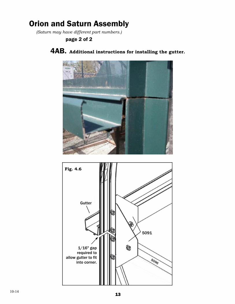
4AB. Additional instructions for installing the gutter.
Orion and Saturn Assembly (Saturn may have different part numbers.)
page 2 of 2
Fig. 4.6
Gutter
1/16" gap required to
allow gutter to fit into corner.
10-14
5091
5096
13

3
006.01.1212
100143x
100243x
20461x
20481x
20891x
20901x
20911x
20922x
20941x
21001x
50011x
50021x
50342x
50351x
50361x
50411x
50421x
50472x
50751x
50761x
50912x
50961x
50971x
3.10/3.11
3.2
3.1
5035 5036
5096 5097
2046 5034
5041
5034
5042
5047 50472100
2091
2048
5091
5075 5076
3.1
3.8
3.9
3.3 3.4
5047
1002
5002
3.110
5075
2046
2100
5047
2089/5096
5041 5035 5036
2091
2048
2089
5075
2092
3.6 3.73.5
2048
2100 2094
2091 2094
5047
2048
50025047
5041
3.112048
1001
2100
3.123.12 2048204855047
1002 1001
2089 2090
3.3
3.3
3.9
3.8
3.4/3.63 4/3 6
3.5/3.7
5091
3.2
5034
50355091
5096
5075
2094
Saturn
14 end view
Door Track
�� Door Track

4A
006.01.1212
670
0
830
0
990
0
1150
0
1001
26 26 26 26
1002
28 28 28 28
1005
2 2 2 2
1010
2 2 2 2
1092
4 4 4 4
2050
2051
2052
2053
1 1 1 1
5043
2 2 2 2
6060
2 2 2 2
4.6
4 54.5
43504
2050205120522053
4.144.2
4.4
4.1 4.3
4.6
50435
100511010
4.250365091
5097
5036750278502895029050301503
503420222023202420255022
2046
4.4
1092 1092
2091
4.5
1092
2050/20512052/20532052/2053
5050
2050/20512052/2053
5050
4.3
50275028502950305031
6060
Saturn
15
Ridge Beam
outside view
outside view outside view

4B
006.01.1212
670
0
830
0
990
0
1150
0
1001
42 52 66 76
1002
42 52 66 76
1017
4 4 4 4
2057
3 4 5 6
5049
4 4 4 4
5055
6 8 10 12
5063
5064
5065
5066
2 2 2 2
4.7
4.11
4.7
4.8
4.10
4.11
5049
4.10
1017
3
3
4
4
5
5
5063506450655066
4.13
4.12
5036
4.9
2057
5055
4.9
5055
4.8
5055
5028502950305031
4.12
5049
4.13
1032
2050/20512052/2053
5050
50365035
5055
Saturn
16
Ridge Beam
outside view
outside view Ridge Beam
Roof Brace
5028-5031 GutterRafter
Door Track
5063-50665063-5066
Support

5
006.01.1212
10012x
10022x
100316x
10042x
10072x
10092x
10142x
10152x
10591x
10601x
10612x
10621x
11111x
11121x
11131x
15001x
15151x
20051x
20062x
50211x
50581x
50981x
5.22
1061
1059
1062
1060
5.22
5.55
5058 5098
5R.35
2006 2005
5.44
55.1
101410031003
1060 5.221061
1003
.35R.
11001
1002
1062
1059
5.410621004
10151009
1007
5021
5.5
5.710015
5.6
15151500
5021
5058
5047
5058 5058
1111
1112
11131113
5058
5098
5.15.665.885
5.8
10141014
5021
20462046
03100
Saturn
17
Right
outside view
inside view
outside view
outside view end view

5
006.01.1212
10012x
10023x
100316x
10042x
10072x
10092x
10142x
10152x
10591x
10601x
10612x
10621x
11111x
11121x
11131x
15001x
15151x
20011x
50211x
50581x
50991x
5.2
1061
1059
1062
1060
5.2
5.15.65.8
5.5
5099 5058
5.45B.85
5.8
10141014
5021
20462046
1111
1112
11131113
2001
5047
1002
5L.3
15.1
101410031003
1060 5.251061
1003
5.41062 1004
10151009
1007
5021
5.5
5.710015
5.6
15151500
5021
5058
5047
5058 5058
5058
5L.3
1001
1002
10003
1062
1059
5099
Saturn
18
Left
end view
outside view
outside view
outside view
outside view
inside view
inside view
of Door Track

6
006.01.1212
5000
6700
8300
9900
1150
0
1x 2x 2x 4x 4x
1001
4 8 8 16 16
1002
4 8 8 16 16
1006
6 12 12 24 24
1019
1 2 2 4 4
1063
1 2 2 4 4
1064
1 2 2 4 4
1065
2 4 4 8 8
1066
1 2 2 4 4
1067
1 2 2 4 4
2016
2 4 4 8 8
6 66.6
6.4
6.7
6.5
6.81063
20161006
1065
1001
1019
1064
1067
6.2
Art. No. mm 6700 8300 9900 115004 3679491 600 x 544 2 4 4 4
20502051205220535050
1065 1064 1065 1064
1066 1066 10651065
1066
1064
1065 1065
Saturn
19
Hinge 1064
Glass Assembly bottom (inside) view
For Glass bottom inside view
For Polycarbonate bottom inside view
top view
top view
end view
Vent
outside view outside view

20
Vitavia Saturn Glass List Glass glazing method 7A
Code Dimensions 8x8 (6700) 8x10 (8300) 1 24" x 24" 34 38 2 24" x 21-5/8" 6 6 3 24" x 29" 8 10 4 23-5/8" x 21-3/8" 2 2 5 24" x 32-5/8" curved 4 4 6 24" x 17-1/16" x 5/16" 4 4 7 24" x 32-1/2" 2 2
5090 24" x 24" Acrylic Curve 8 10
8x12 (9900) 42 8 12 4 4 4 2 12
8x14 (11500) 46 10 14 4 4 4 2 14
Vitavia Saturn 8 wide 12-14
Preformed clips Aluminum bendable clips
6 6
5 7 7 5
1 1 1 1
1 1 1 1
Recommended locations for optional Louver Window
4 4
4
4
2
2 2
2
2
3 3
3 3
3 3
3
1 1
1 1
1 1
1
1 1
1 1
1 1
1
5
1
1
5
1
1
1
1
1
1
1
1
6 6
For TwinWall Glazing See Pages 21, 22, 23, 24

6 mm TwinWall Polycarbonate Parts List Code Dimensions 8x8 8x10 8x12 8x14
A 24" x Pattern 2 2 2 2 B 24" x 80" 2 2 2 2 C 24" x Pattern 2 2 2 2 E 24" x 17" x 1/4" 2 2 2 2 F 24" x 1/4" x 17" 2 2 2 2 W 24" x 47-3/4" 8 10 12 14
D 24" x 24" 6 6 6 6 R 24" x 74" 6 8 8 10
VR 24" x 52-7/8" 2 2 4 4 V 23-5/8" x 21-3/8" 2 2 4 4
Accessories 24" 6 mm U-Channel - Aluminum - Bottom of A, B, C, W, E, F 18 20 22 24
24" 6 mm U-Channel - Poly - Top of W & B 10 12 14 16
22" 6 mm U-Channel - Poly - Top of A & C 4 4 4 4 Z7520 FOAM TAPE - 3/8" x 5/16" thick, feet 12 ft 16 ft 16 ft 20 ft
Silicone Sealant 1 1 2 2
4.5 mm TwinWall Polycarbonate Parts List
29-1/4" 6 mm U-Channel - Poly - Top of E & F 4 4 4 4
24" 4.5 mm U-Channel - Aluminum - Bottom of R & V panels, Top & Bottom of VR & D panels 24 26 32 34
B7525 Breathable Poly Tape, 1" wide, feet 21 ft 25 ft 29 ft 33 ft
Vitavia Saturn (aka Diana) 8 wide meh/tsp 12-14
Vitavia Saturn TwinWall List
A
D
C D
D
D
D
D
F E
R VR
R R
R
R VR W
W W
W W
W W
8' L 10' L
12' L 14' L
A C B B
F E
V
V
V
V
DOOR END
BACK WALL � FOAM TAPE – Apply to both sides of ridge beam before glazing - except where there is a roof vent. (See attached instructions.)
� BREATHABLE TAPE – Apply to top of V and R panels. (See attached instructions.)
Tape
Tape
Tape
Tape
21

Taping Multi-Wall Panels
Peel plastic coating from edge
Overlap tape 1/4" onto panel
Press tape into place
Mark “outside” of panel revised Fall 2012
NOTE: Inspect the panels and read the information printed on the protective film. One side of the panel is specially treated to face the sun.
When the panels were cut to size, small particles may have entered the flute channels. Compressed air has been used to clear the flutes. Peel off the protective film from the inside of the panel and inspect the panel closely. Remove any remaining particles with a vacuum or compressed air. Do not flush the flutes with water because it may take a long time to dry out.
The ends of the polycarbonate panels should be protected to keep out dust and insects. This is done with a special breath-able tape, aluminum channel, clear polycarbonate channel, or by fitting the panel into a groove in the greenhouse framework.
Apply 1" wide Breathable Tape (B7524) 1) Lay out Multi-Wall panel on clean, flat surface with UV side down and end to be taped next to you.
2) Peel back plastic film on each side of Multi-Wall panel, about 4"-6" from edge.
3) Measure Multi-Wall panel width; cut tape to length.
4) Peel off protective backing from Breathable Tape.
5) With one end of tape in each hand, start one end with about 1/4" overlap onto panel. Pulling tight with opposite hand, press other end in place with 1/4" overlap onto panel.
6) Using fingers, press tape evenly across end and then fold onto back side and smooth out back side.
NOTE: Only remove the panel protective film from the inside of the panels before installation. Peel back the outside protective film about 4" from the edge, but leave the outside film on the panel until after installation is complete. (It is difficult or impossible to tell the inside from the outside once both films have been removed. You may want to place a small mark with a permanent marker at one corner of the panel to avoid future confusion.)
WARNING: Do not store panels in direct sunlight. The protective film would become very difficult to remove.
revised May 2013 page 2 of 4 22

A. Foam Tape
Apply to ridge beam or ledger - except where there is a roof vent - before installing your polycarbonate panels.
Roll size: 3/8" wide x 5/16" thick x 10 ft. long (#Z7520)
The purpose of this Foam Tape is to support the polycarbonate panels at the top, and to pro- vide better sealing where there could be significant heat loss.
Refer to the illustration ( XXXX) on where to place the Foam Tape. (Install along both sides of Ridge Beam for free-standing green-houses, and along the Ledger for home-attached greenhouses – except where there is a roof vent.)
Cut the tape to fit between the rafters, and install the tape on the Ridge Beam or Ledger. B. Silicone Sealant 1. Apply 1/8" bead silicone where polycarbonate panels fit into Ridge Beam or Ledger. 2. Apply 1/8" bead where polycarbonate panels fit into aluminum channels (inside and outside). 3. Apply 1/16" bead to outside top and bottom of vent panels.
Foam Tape
V
W W W W W
R R R VR VR V
R
W
Charley’s Greenhouse Sealing Tips
5-14 CSY
Foam Tape
Roof Corner Bar Ridge
23

Manufacturer-Approved Cleaning Procedures for Multi-Wall Polycarbonate, Acrylic & APET
The UV-resistant surface treatment on one side of the polycarbonate sheet significantly improves long-term weatherability. Periodic cleaning using proper procedures and compatible cleaners is recommended to prolong the service life. For general cleaning, it is recommended that the following instructions and cleaning agents be used. These procedures and cleaners are also recommended for use on the untreated, interior surface of the poly- carbonate sheet, and for acrylic and APET plastics. CLEANING PROCEDURES 1. Rinse sheet with lukewarm water. 2. Wash sheet with a mild soap and lukewarm water. 3. Use a soft cloth or sponge and gently wash with an up and down
motion in the same direction as the flutes, as shown in Fig. 3. 4. Rinse the cloth or sponge and change the water often.
DO NOT SCRUB or use brushes or squeegees. The coating on polycarbonate sheets is UV-resistant; IT IS NOT A MAR-RESISTANT COATING.
5. Repeat rinse and dry with a soft cloth to prevent water spotting.
IMPORTANT: If a material is found to be incompatible in a short-term test, it will usually be found to be incompatible in the field. The converse, however, is not always true. Favorable performance is no guarantee that actual end-use conditions have been duplicated. Therefore, these results should be used as a guide only and the products must be tested under actual end-use conditions by the user.
Polycarbonate sheets are treated on one side for protection against UV damage. This treated side must face outward or toward the light source to provide protection for polycarbonate sheet.
Cleaning Agents that have been found to be COMPATIBLE with polycarbonate sheets under laboratory conditions: Freon T.F. Joy Palmolive Liquid Top Job VM&P grade Naptha Windex with Ammonia Brillianize®
Cleaning Agents that have been found to be INCOMPATIBLE with polycarbonate sheets under labo-ratory conditions and should NOT be used: Lysol Pinesol Butyl Cellosolve DO NOT USE Isopropanol Formula 409
17979 SR 536 • Mount Vernon, WA 98273 Phone (800) 322-4707 • 360-395-3001
charleysgreenhouse.com
Charley’s © Copyright Charley’s Greenhouse & Garden
Spring 2014
Fig 3
(Gently wash with an up and down motion in the same direction as the flutes.)
page 4 of 4

006.01.1212