saudi standard no2974 - inmetro.gov.brpontofocal... · saudi arabian standard saso iec...
TRANSCRIPT

SAUDI ARABIAN STANDARD SASO IEC 60601-1-3/2011
SAUDI STANDARD NO2974
MEDICAL ELECTRICAL EQUIPMENT –
Part 1-3: General requirements for basic safety and essential performance –
Collateral Standard: Radiation protection in diagnostic X-ray equipment
SAUDI ARABIAN STANDARDS ORGANIZATION ---------------------------------------------------------------------------------------------THIS DOCUMENT IS A DRAFT SAUDI STANDARD CIRCULATED FOR COMMENTS. IT IS, THEREFORE, SUBJECT TO CHANGE AND MAY NOT BE REFERRED TO AS A SAUDI STANDARD UNTIL APPROVED BY THE BOARD OF DIRECTORS.

SAUDI ARABIAN STANDARD SASO IEC 60601-1-3/2011
1
CONTENTS
FOREWORD.........................................................................................................................4 1 Scope, object and related standards ...............................................................................5
1.1 Scope....................................................................................................................5 1.2 Object ...................................................................................................................5 1.3 Related standards .................................................................................................5
1.3.1 IEC 60601-1 ..............................................................................................5 1.3.2 Particular standards ...................................................................................5
2 Normative references .....................................................................................................6 3 Terms and definitions .....................................................................................................6 4 General requirements ...................................................................................................16
4.1 Statement of compliance......................................................................................16 4.2 Composition of reference materials ......................................................................16
5 ME EQUIPMENT identification, marking and documents ....................................................16 5.1 Marking on the outside of ME EQUIPMENT or ME EQUIPMENT parts............................16
5.1.1 General ...................................................................................................16 5.1.2 Marking requirements in subclauses .........................................................16
5.2 ACCOMPANYING DOCUMENTS ..................................................................................16 5.2.1 References in subclauses ........................................................................17 5.2.2 Dosimetric calibration...............................................................................17 5.2.3 General requirements for the reference of subassemblies and
ACCESSORIES ............................................................................................17 5.2.4 Instructions for use ..................................................................................18
6 RADIATION management ................................................................................................19 6.1 General ...............................................................................................................19 6.2 Initiation and termination of the IRRADIATION .........................................................20
6.2.1 Normal initiation and termination of the IRRADIATION ..................................20 6.2.2 Safety measures against failure of normal termination of the
IRRADIATION ..............................................................................................20 6.3 RADIATION dose and RADIATION QUALITY ................................................................20
6.3.1 Adjustment of RADIATION dose and RADIATION QUALITY................................20 6.3.2 Reproducibility of the RADIATION output .....................................................20
6.4 Indication of operational states ............................................................................21 6.4.1 Indication of the X-RAY SOURCE ASSEMBLY selected ....................................21 6.4.2 Indication of LOADING STATE......................................................................21 6.4.3 Indication of LOADING FACTORS and MODES OF OPERATION ...........................21 6.4.4 Indication of automatic modes ..................................................................21 6.4.5 Dosimetric indications ..............................................................................22
6.5 AUTOMATIC CONTROL SYSTEM.................................................................................22 6.6 SCATTERED RADIATION reduction............................................................................22 6.7 Imaging performance ...........................................................................................22
6.7.1 General ...................................................................................................22 6.7.2 System performance ................................................................................22 6.7.3 Nominal focal spot value ..........................................................................23

SAUDI ARABIAN STANDARD SASO IEC 60601-1-3/2011
2
6.7.4 RADIATION DETECTOR or X-RAY IMAGE RECEPTOR .........................................23 7 RADIATION QUALITY ........................................................................................................23
7.1 HALF-VALUE LAYERS and TOTAL FILTRATION in X-RAY EQUIPMENT ..............................23 7.2 Waveform of the X-RAY TUBE VOLTAGE...............................................................24 7.3 Indication of FILTER properties ..............................................................................24 7.4 Test for FILTRATION by irremovable materials ........................................................24 7.5 Test for ADDED FILTERS and materials ...................................................................25 7.6 Test for HALF-VALUE LAYER....................................................................................25
8 Limitation of the extent of the X-RAY BEAM and relationship between X-RAY FIELD and IMAGE RECEPTION AREA ............................................................................................25 8.1 General ...............................................................................................................25 8.2 Enclosure of X-RAY TUBES ....................................................................................25 8.3 Limiting DIAPHRAGM in X-RAY TUBE ASSEMBLIES ......................................................26 8.4 Confinement of EXTRA-FOCAL RADIATION ................................................................26 8.5 Relationship between X-RAY FIELD and IMAGE RECEPTION AREA...............................26
8.5.1 General ...................................................................................................26 8.5.2 * FOCAL SPOT TO IMAGE RECEPTOR DISTANCE ...............................................26 8.5.3 Correspondence between X-RAY FIELD and EFFECTIVE IMAGE
RECEPTION AREA .......................................................................................26 8.5.4 Positioning of the PATIENT and restriction of the irradiated area .................27
9 FOCAL SPOT TO SKIN DISTANCE ........................................................................................27 9.1 General ...............................................................................................................27 9.2 Information in the ACCOMPANYING DOCUMENTS .......................................................27
10 ATTENUATION of the X-RAY BEAM between the PATIENT and the X-RAY IMAGE RECEPTOR .....................................................................................................................27 10.1 General ...............................................................................................................27 10.2 Information in the ACCOMPANYING DOCUMENTS .......................................................27
11 Protection against RESIDUAL RADIATION...........................................................................28 12 * Protection against LEAKAGE RADIATION .........................................................................28
12.1 General ...............................................................................................................28 12.2 Mounting of X-RAY SOURCE ASSEMBLIES and X-RAY IMAGING ARRANGEMENTS ............28 12.3 Statement of reference LOADING conditions...........................................................29 12.4 LEAKAGE RADIATION in the LOADING STATE ..............................................................39 12.5 LEAKAGE RADIATION when not in the LOADING STATE ...............................................30
13 Protection against STRAY RADIATION ...............................................................................30 13.1 General ...............................................................................................................30 13.2 Control of X-RAY EQUIPMENT from a PROTECTED AREA .............................................30 13.3 Protection by distance .........................................................................................31 13.4 * Designated SIGNIFICANT ZONES OF OCCUPANCY ....................................................31 13.5 Handgrips and control devices .............................................................................32 13.6 * Test for STRAY RADIATION ...................................................................................32
Annex A (informative) General guidance and rationale........................................................34 Annex B (normative) Values of the series R'10 and R'20, ISO 497 ......................................36 Annex C (informative) Mapping between this Edition 2 of IEC 60601-1-3 and Edition 1........37 Bibliography .......................................................................................................................39

SAUDI ARABIAN STANDARD SASO IEC 60601-1-3/2011
3
Index of defined terms used in this collateral standard .........................................................41 Figure 1 – Example of presentation of data on STRAY RADIATION ...........................................33 Table 1 – Subclauses containing requirements for marking ..................................................16 Table 2 – Subclauses requiring statements in ACCOMPANYING DOCUMENTS ............................17 Table 3 – HALF-VALUE LAYERS in X-RAY EQUIPMENT ...............................................................24

SAUDI ARABIAN STANDARD SASO IEC 60601-1-3/2011
4
FOREWORD
The Saudi Standards,Metrology and Quality Organization (SASO) has adopted the International Standard IEC 60601-1-3 “MEDICAL ELECTRICAL EQUIPMENT – Part 1-3: General requirements for basic safety and essential performance –Collateral Standard:Radiation protection in diagnostic X-ray equipment ” issued by the International Electrotechnical Commission (IEC). It has been adopted without any technical modifications with a view to its approval as a Saudi standard.

SAUDI ARABIAN STANDARD SASO IEC 60601-1-3/2011
5
MEDICAL ELECTRICAL EQUIPMENT –
Part 1-3: General requirements for basic safety and essential performance –
Collateral Standard: Radiation protection in diagnostic X-ray equipment
1 Scope, object and related standards
1.1 Scope
This International Standard applies to the BASIC SAFETY and ESSENTIAL PERFORMANCE of MEDICAL ELECTRICAL EQUIPMENT and MEDICAL ELECTRICAL SYSTEMS, hereafter referred to as ME EQUIPMENT and ME SYSTEMS.
This collateral standard applies to X-RAY EQUIPMENT and to subassemblies of such equipment, where RADIOLOGICAL IMAGES of a human PATIENT are used for diagnosis, planning or guidance of medical procedures.
1.2 Object
The object of this collateral standard is to specify general requirements that are in addition to those of the general standard and to serve as the basis for particular standards.
The object of this collateral standard is to establish general requirements for protection against X-RADIATION in X-RAY EQUIPMENT, in order that the IRRADIATION of the human PATIENT, the OPERATOR, staff and members of the public can be kept as low as reasonably achievable, without jeopardizing the benefit of the RADIOLOGICAL procedure. Particular standards may specify their appropriate values and/or measures for general requirements specified in this collateral standard. The implementation of the general requirements or the reference to the particular standard instead, shall be justified in the RISK MANAGEMENT process.
This collateral standard considers RADIATION PROTECTION aspects related to X-RADIATION only.
Requirements for the control of the electrical energy used to generate X-RADIATION, which is also an important aspect of RADIATION PROTECTION, are included in IEC 60601-1 and in particular standards for the safety and ESSENTIAL PERFORMANCE of the EQUIPMENT concerned.
1.3 Related standards
1.3.1 IEC 60601-1
For ME EQUIPMENT and ME SYSTEMS, this collateral standard complements IEC 60601-1.
When referring to IEC 60601-1 or to this collateral standard, either individually or in combination, the following conventions are used:
• "the general standard" designates IEC 60601-1 alone;
• "this collateral standard" designates IEC 60601-1-3 alone;
• "this standard" designates the combination of the general standard and this collateral standard.
SAUDI ARABIAN STANDARD SASO IEC 60601-1-3/2011
6
1.3.2 Particular standards
A requirement in a particular standard takes priority over the corresponding requirement in this collateral standard.
2 Normative references
The following referenced documents are indispensable for the application of this document. For dated references, only the edition cited applies. For undated references, the latest edition of the referenced document (including any amendments) applies.
IEC 60336, Medical electrical equipment – X-ray tube assemblies for medical diagnosis- Characteristics of focal spots
IEC 60522:1999, Determination of the permanent filtration of X-ray tube assemblies
IEC 60601-1:2005, Medical electrical equipment – Part 1: General requirements for basic safety and essential performance
IEC 60788:2004, Medical electrical equipment – Glossary of defined terms
ISO 497, Guide to the choice of series of preferred numbers and of series containing more rounded values of preferred numbers
3 Terms and definitions
For the purposes of this document, the terms and definitions given in IEC 60601-1:2005, IEC 60788:2004 and the following apply.
NOTE An index of defined terms is found beginning on page 42.
3.1 ACCESSIBLE SURFACE surface of EQUIPMENT or of an EQUIPMENT part that can be easily or accidentally touched by persons without the use of a TOOL
3.2 ADDED FILTER removable or irremovable FILTER positioned in the RADIATION BEAM to provide part or all of the ADDITIONAL FILTRATION
3.3 ADDITIONAL FILTRATION QUALITY EQUIVALENT FILTRATION due to ADDED FILTERS and other removable materials in the RADIATION BEAM which are between the RADIATION SOURCE and the PATIENT or a specified plane
3.4 AIR KERMA K quotient of dEtr by dm, where dEtr is the sum of the initial kinetic energies of all the charged particles liberated by uncharged particles in a mass dm of air, thus
mEK d
d tr=
Unit: J kg–1

SAUDI ARABIAN STANDARD SASO IEC 60601-1-3/2011
7
The special name for the unit of AIR KERMA is gray (Gy) (ICRU 60) [20]
[IEC 60580:2000, definition 3.2, modified] [8]
3.5 AIR KERMA RATE K& quotient of dK by dt, where dK is the increment of AIR KERMA in the time interval dt, thus
tKK
dd
=&
Unit: J kg–1 s–1
If the special name gray is used, the unit of AIR KERMA RATE is gray per second (Gy s–1) (ICRU 60) [20]
[IEC 60580:2000, definition 3.3] [8]
3.6 AMBIENT DOSE EQUIVALENT H*(d) at a point in a RADIATION FIELD, the DOSE EQUIVALENT that would be produced by corresponding expanded and aligned field, in the ICRU sphere at a depth, d, on the radius opposing the direction of the aligned field
Unit: J kg–1
The special name for the unit of AMBIENT DOSE EQUIVALENT is sievert (Sv) (ICRU 51) [19]
3.7 ATTENUATION reduction of a RADIATION QUANTITY upon passage of the RADIATION through matter resulting from all types of interaction with this matter
NOTE The RADIATION QUANTITY may be, for example, the particle flux density or the energy density. ATTENUATION does not include the geometric reduction of the RADIATION QUANTITY with distance from the RADIATION SOURCE.
3.8 ATTENUATION EQUIVALENT δ thickness of a layer of reference material which, if substituted for the material under consideration in a beam of specified RADIATION QUALITY and under specified geometrical conditions, gives the same degree of ATTENUATION. ATTENUATION EQUIVALENT is expressed in suitable submultiples of the metre together with the reference
3.9 AUTOMATIC CONTROL SYSTEM in an X-RAY EQUIPMENT, system in which the control or limitation of the electric energy delivered to an X-RAY TUBE ASSEMBLY depends upon the measurement of one or more RADIATION QUANTITIES or corresponding physical quantities
3.10 AUTOMATIC EXPOSURE CONTROL in an X-RAY EQUIPMENT, MODE OF OPERATION in which one or more LOADING FACTORS are controlled automatically in order to obtain at a pre-selected location a desired quantity of RADIATION

SAUDI ARABIAN STANDARD SASO IEC 60601-1-3/2011
8
3.11 BEAM LIMITING DEVICE device to limit the RADIATION FIELD
3.12 BEAM LIMITING SYSTEM entirety of parts and their geometrical configuration contributing to the limitation of the RADIATION BEAM
3.13 CONTINUOUS ANODE INPUT POWER specified highest ANODE INPUT POWER which can be applied to the ANODE continuously
Unit: W
3.14 CONTROL PANEL part of EQUIPMENT for the purpose of controlling all, or some, of the functions of the EQUIPMENT. The CONTROL PANEL may contain devices for indicating and displaying operating factors
3.15 CONTROLLED AREA defined area which is part of an area under surveillance and for which access, occupancy and working conditions are regulated and controlled in order to protect persons against IONIZING RADIATION
3.16 CURRENT TIME PRODUCT in MEDICAL RADIOLOGY, quantity of electricity resulting from the LOADING of an X-RAY TUBE, expressed in milliampere seconds, as the product of the mean X-RAY TUBE CURRENT in milliamperes and the duration of the LOADING in seconds
3.17 DIAPHRAGM BEAM LIMITING DEVICE with either a fixed or an adjustable aperture in one plane
3.18 DOSE EQUIVALENT H is the product of Q and D, at a point in tissue, where D is the ABSORBED DOSE and Q is the quality factor at that point, thus
H = Q D.
Unit: J kg–1
The special name for the unit of DOSE EQUIVALENT is sievert (Sv) (ICRU 51) [19]
3.19 EDGE FILTER FILTER whose ABSORPTION characteristic as a function of RADIATION ENERGY shows a discontinuity in the useful photon energy range

SAUDI ARABIAN STANDARD SASO IEC 60601-1-3/2011
9
3.20 EFFECTIVE IMAGE RECEPTION AREA part of the IMAGE RECEPTION AREA that is configured to receive an X-RAY PATTERN that can be processed for display or storage
NOTE 1 In accordance with this convention, the IMAGE RECEPTION AREA of a multi-field X-ray image intensifier tube is considered to be restricted by the selection of magnification modes, to exclude any portion of the input screen from which the X-RAY PATTERN is not electronically processed.
NOTE 2 For X-RAY EQUIPMENT based on scanning that varies the position for receiving an X-RAY PATTERN during the exposure, the EFFECTIVE IMAGE RECEPTION AREA at a certain time during the scan is the area of the image receptor that is receiving and processing an X-RAY PATTERN at that very moment.
3.21 ENTRANCE SURFACE in RADIOLOGY, plane or curved surface through which the RADIATION enters an irradiated object
3.22 EXTRA-FOCAL RADIATION in an X-RAY SOURCE ASSEMBLY, X-RADIATION emitted from the RADIATION SOURCE other than that emitted from the ACTUAL FOCAL SPOT
3.23 FILTER in RADIOLOGICAL EQUIPMENT, material or device provided to effect FILTRATION of the RADIATION BEAM
3.24 FILTRATION modification of characteristics of IONIZING RADIATION on passing through matter
NOTE FILTRATION may be:
– preferential ABSORPTION of certain components of polyenergetic X-RADIATION accompanying its ATTENUATION;
– a modification of the distribution of RADIATION intensity over the cross-section of a RADIATION BEAM
3.25 FOCAL SPOT TO IMAGE RECEPTOR DISTANCE distance from the REFERENCE PLANE of an EFFECTIVE FOCAL SPOT to the point at which the REFERENCE AXIS intersects with the image receptor plane
3.26 FOCAL SPOT TO SKIN DISTANCE in MEDICAL DIAGNOSTIC RADIOLOGY, distance from the REFERENCE PLANE of an EFFECTIVE FOCAL SPOT to a plane normal to the REFERENCE DIRECTION and containing the point on the PATIENT surface nearest to the RADIATION SOURCE
3.27 HALF-VALUE LAYER thickness of a specified material, which attenuates under NARROW BEAM CONDITIONS X- RADIATION with a particular spectrum to an extent such that the AIR KERMA RATE, EXPOSURE RATE or ABSORBED DOSE rate is reduced to one half of the value that is measured without the material. The HALF-VALUE LAYER (HVL) is expressed in suitable submultiples of the metre together with the material.
3.28 IMAGE RECEPTION AREA in RADIOLOGY, surface on which an X-RAY PATTERN is received

SAUDI ARABIAN STANDARD SASO IEC 60601-1-3/2011
10
3.29 IONIZING RADIATION RADIATION consisting of directly or indirectly ionizing particles or a mixture of both. By convention, ultraviolet radiation is excluded
3.30 IRRADIATION exposing of a living being or matter to RADIATION. In RADIOLOGY, exposing of a living being or matter to IONIZING RADIATION
Thus: X-IRRADIATION
3.31 IRRADIATION SWITCH in RADIOLOGICAL EQUIPMENT, control device provided to initiate and/or stop IRRADIATION
3.32 IRRADIATION TIME duration of an IRRADIATION determined according to specific methods, usually the time a rate of a RADIATION QUANTITY exceeds a specified level
3.33 LEAKAGE RADIATION IONIZING RADIATION which has passed through the PROTECTIVE SHIELDING of a RADIATION SOURCE as well as that which, for some types of X-RAY GENERATORS, has passed through the RADIATION APERTURE before and after LOADING (for example one containing a grid controlled X-RAY TUBE)
3.34 LOADING in an X-RAY GENERATOR, act of supplying electrical energy to the ANODE of an X-RAY TUBE
3.35 LOADING FACTOR factor influencing by its value the X-RAY TUBE LOAD, for example X-RAY TUBE CURRENT, LOADING TIME, CONTINUOUS ANODE INPUT POWER, X-RAY TUBE VOLTAGE and PERCENTAGE RIPPLE
3.36 LOADING STATE for an X-RAY GENERATOR, state from the end of the READY STATE, when the intended function of the generator is initiated, until the end of the LOADING of the X-RAY TUBE
3.37 LOADING TIME time determined according to a specific method, during which the ANODE INPUT POWER is applied to the X-RAY TUBE
3.38 MEASURED VALUE estimate of the TRUE VALUE of a quantity, derived from the INDICATED VALUE of a meter after applying all relevant CORRECTION FACTORS
3.39 MEDICAL RADIOLOGY branch of RADIOLOGY applied to human and veterinary medicine as well as to dentistry and chiropractic

SAUDI ARABIAN STANDARD SASO IEC 60601-1-3/2011
11
3.40 MODE OF OPERATION for X-RAY EQUIPMENT the technical state defined by a configuration of several predetermined LOADING FACTORS and other settings for RADIOSCOPY or RADIOGRAPHY, selectable simultaneously by the operation of a single control NOTE 1 Selection of a particular mode does not necessarily define the values of all the parameters affecting its use.
NOTE 2 Values defined by selection of a particular mode are not necessarily invariable during its use.
3.41 NARROW BEAM CONDITION arrangement for the measurement of a RADIATION QUANTITY in a NARROW BEAM of IONIZING RADIATION
3.42 NOMINAL X-RAY TUBE VOLTAGE highest permitted X-RAY TUBE VOLTAGE for specific operating conditions
3.43 PATIENT ENTRANCE REFERENCE POINT point intended to represent the intersection of the X-RAY BEAM AXIS with the ENTRANCE SURFACE of the PATIENT
NOTE The geometries to be used for various X-RAY EQUIPMENT are given in the particular standards.
3.44 PERCENTAGE RIPPLE for a HIGH-VOLTAGE GENERATOR, ratio of the difference between the highest and the lowest values of a rectified voltage waveform during a cycle of the supply to the highest value, expressed as a percentage
3.45 PERMANENT FILTRATION the QUALITY EQUIVALENT FILTRATION effected in an X-RAY TUBE ASSEMBLY by permanently fixed materials intercepting the X-RAY BEAM, that are not intended to be removed for any application and are not provided with means for removal in NORMAL USE
3.46 PHANTOM device intended to simulate parts of the PATIENT for test purposes
3.47 PRIMARY PROTECTIVE SHIELDING PROTECTIVE SHIELDING for attenuating RESIDUAL RADIATION
3.48 PROTECTED AREA defined area within an area under surveillance or within a CONTROLLED AREA which is protected by STRUCTURAL SHIELDING or by distance so that the resulting level of RADIATION is lower than the ambient level in the overall area of which it is a part
3.49 PROTECTIVE BARRIER PROTECTIVE SHIELDING in the form of attenuating material provided for RADIOLOGICAL protection

SAUDI ARABIAN STANDARD SASO IEC 60601-1-3/2011
12
3.50 PROTECTIVE DEVICE in RADIOLOGY, device for the purpose of RADIOLOGICAL protection
Thus:
− PROTECTIVE CLOTHING:
− PROTECTIVE APRON;
− PROTECTIVE SKIRT;
− PROTECTIVE GLOVE;
− PROTECTIVE GLASSES;
− mobile PROTECTIVE BARRIER
3.51 PROTECTIVE SHIELDING in RADIOLOGY, material that limits the extent of the RADIATION BEAM or attenuates STRAY RADIATION
NOTE PROTECTIVE SHIELDING may include materials provided for RADIOLOGICAL protection, or devices or materials provided for other purposes, which attenuate IONIZING RADIATION.
3.52 QUALITY EQUIVALENT FILTRATION quantitative indication of the FILTRATION effected by one or several layer(s) of reference material(s) which, if substituted in a beam of specified RADIATION QUALITY under NARROW BEAM CONDITION for the material under consideration, give(s) the same RADIATION QUALITY as for the material under consideration. The QUALITY EQUIVALENT FILTRATION is expressed in suitable submultiples of the metre together with the reference material(s)
3.53 RADIATION propagation of emitted energy through space or through a material medium in the form of waves or in the form of kinetic energy of particles
NOTE When unqualified, the term RADIATION usually refers to
– electromagnetic radiations according to frequency or origin such as: radiofrequency radiation, infra-red radiation, visible radiation (light), ultraviolet radiation, X-RADIATION, gamma radiation;
– corpuscular radiations according to particles or origin such as: alpha radiation, beta radiation, electron radiation, neutron radiation.
3.54 RADIATION APERTURE aperture in the PROTECTIVE SHIELDING of a RADIATION SOURCE or in a BEAM LIMITING DEVICE, that is intended to give passage to the RADIATION BEAM
3.55 RADIATION BEAM in RADIOLOGY, spatial region limited in solid angle and containing a flux of IONIZING RADIATION originating from a RADIATION SOURCE that is considered as a POINT SOURCE. LEAKAGE RADIATION and SCATTERED RADIATION are considered not to form a RADIATION BEAM.
Thus: X-RAY BEAM
3.56 RADIATION CONDITION description of RADIATION FIELDS by a set of electrical and geometrical parameters such as X-RAY TUBE VOLTAGE, TOTAL FILTRATION and geometrical arrangements.
SAUDI ARABIAN STANDARD SASO IEC 60601-1-3/2011
13
NOTE The term RADIATION CONDITION refers to a description of RADIATION FIELDS and not to a particular set-up for testing of EQUIPMENT.
3.57 RADIATION DETECTOR EQUIPMENT, generally a sub-assembly or substance which, in the presence of RADIATION, provides by either direct or indirect means a signal or other indication suitable for use in measuring one or more quantities of the incident RADIATION
3.58 RADIATION FIELD area on a surface intersected by a RADIATION BEAM within which the RADIATION intensity exceeds a specific or specified level.
Thus: X-RAY FIELD
3.59 RADIATION PROTECTION limitation to an acceptable level of:
− RADIATION hazard;
− damage to material attributable to RADIATION.
3.60 RADIATION QUALITY characteristic of IONIZING RADIATION determined by the spectral distribution of a RADIATION QUANTITY with respect to RADIATION ENERGY
NOTE For various purposes concerning X-RADIATION, practical approximations of RADIATION QUALITY are expressed in terms of variables such as:
a) high voltage with PERCENTAGE RIPPLE and TOTAL FILTRATION;
b) first HALF-VALUE LAYER for specified high voltage with its PERCENTAGE RIPPLE;
c) first HALF-VALUE LAYER and TOTAL FILTRATION;
d) the first HALF-VALUE LAYER and the quotient of the first HALF-VALUE LAYER by the second HALF-VALUE LAYER;
e) equivalent energy.
3.61 RADIATION SOURCE part of EQUIPMENT capable of emitting IONIZING RADIATION
3.62 RADIATION SOURCE ASSEMBLY assembly of components comprising: – the RADIATION SOURCE, – the means providing protection against IONIZING RADIATION and, where applicable, against
electric shock, – the BEAM LIMITING SYSTEM. Thus: X-RAY SOURCE ASSEMBLY
3.63 RADIOGRAPHIC RATING for the operation of an X-RAY TUBE, specified combination of conditions and LOADING FACTORS, under which the specified limits of loadability of the X-RAY TUBE are attained

SAUDI ARABIAN STANDARD SASO IEC 60601-1-3/2011
14
3.64 RADIOGRAPHY technique for obtaining, recording and optionally processing directly or after TRANSFER, information contained in an X-RAY PATTERN at an IMAGE RECEPTION AREA intended to be analysed during a time independent from the IRRADIATION TIME
3.65 RADIOLOGICAL referring to IONIZING RADIATION, its generation and application for scientific, medical and technical purposes
3.66 RADIOLOGICAL IMAGE information obtained by using IONIZING RADIATION presented as an image suitable for medical diagnosis
3.67 RADIOLOGICAL INSTALLATION installed RADIOLOGICAL EQUIPMENT including all means for its intended operation
Thus: X-RAY INSTALLATION
3.68 RADIOLOGY science of IONIZING RADIATION and its application 3.69 RADIOSCOPY technique for obtaining continuously or periodically a sequence of X-RAY PATTERNS and presenting them directly or through a TRANSFER and optional processing simultaneously and continuously as visible images, intended to provide real-time guidance to an ongoing action
3.70 REFERENCE AIR KERMA AIR KERMA free in air in the primary X-RAY BEAM measured under specific conditions and expressed at the PATIENT ENTRANCE REFERENCE POINT
3.71 REFERENCE AIR KERMA RATE AIR KERMA RATE free in air in the primary X-RAY BEAM measured under specific conditions and expressed at the PATIENT ENTRANCE REFERENCE POINT
3.72 RESIDUAL RADIATION in MEDICAL RADIOLOGY, that part of the RADIATION BEAM which remains after having passed the plane of the IMAGE RECEPTION AREA and any relevant RADIATION measuring device
3.73 SCATTERED RADIATION IONIZING RADIATION emitted by interaction of IONIZING RADIATION with matter, the interaction being accompanied by a reduction in RADIATION ENERGY and/or by a change in direction of the RADIATION

SAUDI ARABIAN STANDARD SASO IEC 60601-1-3/2011
15
3.74 SIGNIFICANT ZONE OF OCCUPANCY for X-RAY EQUIPMENT, zone with specified boundaries within an area under surveillance or within a CONTROLLED AREA, other than a PROTECTED AREA, that is significant because of the assumed need for persons to occupy it during IRRADIATION
3.75 STRAY RADIATION for IONIZING RADIATION, all RADIATION except that of the specified RADIATION BEAM under consideration, but including its RESIDUAL RADIATION
3.76 STRUCTURAL SHIELDING PROTECTIVE SHIELDING forming part of the building structure of a RADIOLOGICAL INSTALLATION
3.77 TOTAL FILTRATION the total of PERMANENT FILTRATION and ADDITIONAL FILTRATION
3.78 X-RAY EQUIPMENT EQUIPMENT consisting of a combination of an X-RAY GENERATOR, ASSOCIATED EQUIPMENT and ACCESSORIES
3.79 X-RAY GENERATOR combination of all components provided for the generation and control of X-RADIATION, comprising at least the HIGH-VOLTAGE GENERATOR interconnected with an X-RAY SOURCE ASSEMBLY
3.80 X-RAY IMAGING ARRANGEMENT in X-RAY EQUIPMENT, arrangement of RADIATION SOURCE and X-RAY IMAGE RECEPTOR for a specified RADIOLOGICAL technique
3.81 X-RAY IMAGE RECEPTOR device, intended to convert X-RAY PATTERNS into another form, from which a visible image is obtained either directly or indirectly
NOTE Examples of X-ray image receptors are intensifying screens, X-ray image intensifiers, digital X-ray imaging devices and radiation detectors in CT scanners.
3.82 X-RAY PATTERN information contained in an X-RAY BEAM the distribution of intensity of which has been modulated by the object passed
3.83 X-RAY TUBE evacuated vessel for the production of X-RADIATION by the bombardment of a TARGET, usually contained in an ANODE, with ELECTRONS accelerated from a CATHODE by an electric field
Thus: − rotating ANODE X-RAY TUBE;
− double focus X-RAY TUBE

SAUDI ARABIAN STANDARD SASO IEC 60601-1-3/2011
16
3.84 X-RAY TUBE ASSEMBLY X-RAY TUBE HOUSING with an X-RAY TUBE installed
3.85 X-RAY TUBE CURRENT electric current of the ELECTRON beam incident on the TARGET of an X-RAY TUBE. Usually, the X-RAY TUBE CURRENT is expressed by its mean value in milliamperes (mA)
3.86 X-RAY TUBE HOUSING container for an X-RAY TUBE providing protection against electric shock and against X-RADIATION and having a RADIATION APERTURE. It may optionally contain additional components
3.87 X-RAY TUBE LOAD electrical energy supplied to an X-RAY TUBE expressed by a combination of values of LOADING FACTORS
3.88 X-RAY TUBE VOLTAGE potential difference applied to an X-RAY TUBE between the ANODE and the CATHODE. Usually, X-RAY TUBE VOLTAGE is expressed by its peak value in kilovolts (kV)
4 General requirements
4.1 Statement of compliance
Any statement of compliance with the requirements of this collateral standard shall be given in the following form:
xxxx with radiation protection in accordance with IEC 60601-1-3:2008,
where xxxx represents the object (e.g. "X-RAY EQUIPMENT") for which compliance is to be stated.
4.2 Composition of reference materials
Values of ATTENUATION EQUIVALENT, HALF-VALUE LAYER and QUALITY EQUIVALENT FILTRATION shall be expressed in this collateral standard as thicknesses of aluminium of purity 99,9 % or higher.
5 ME EQUIPMENT identification, marking and documents
5.1 Marking on the outside of ME EQUIPMENT or ME EQUIPMENT parts
Additionally to the requirements in Clause 7 of the general standard, the following applies.
5.1.1 General
All subassemblies, components and ACCESSORIES of X-RAY EQUIPMENT that can be removed in NORMAL USE, and are relevant to compliance with this collateral standard, shall be marked to ensure,
– that they can be identified readily and correlated with the ACCOMPANYING DOCUMENTS; – that interchangeable devices are individually distinguishable to the OPERATOR both in
NORMAL USE and for the purpose of obtaining replacements.

SAUDI ARABIAN STANDARD SASO IEC 60601-1-3/2011
17
All markings shall be permanently affixed and clearly legible as defined in Clause 7 of IEC 60601-1.
5.1.2 Marking requirements in subclauses
In this collateral standard particular requirements for marking and for the content of markings are given in various subclauses, as indicated in Table 1.
Table 1 – Subclauses containing requirements for marking
Title Subclause
General 5.1.1
Indication of FILTER properties 7.3
5.2 ACCOMPANYING DOCUMENTS
Additionally to the requirements of the general standard, the following applies.
5.2.1 References in subclauses
The subclauses of this collateral standard that contain requirements for statements in ACCOMPANYING DOCUMENTS (which include instructions for use and technical description) are listed in Table 2.
Table 2 – Subclauses requiring statements in ACCOMPANYING DOCUMENTS
Title Subclause
Dosimetric calibration 5.2.2
General requirements for the reference of subassemblies and ACCESSORIES
5.2.3
General requirements for RADIATION dose information 5.2.4.1
Quantitative information 5.2.4.2
Dose indication 5.2.4.3
Clinical protocols 5.2.4.4
Deterministic effects 5.2.4.5
Risk to OPERATORS 5.2.4.6
Reproducibility of the RADIATION output 6.3.2
Indication of LOADING FACTORS and MODES OF OPERATION 6.4.3
Dosimetric indications 6.4.5
AUTOMATIC CONTROL SYSTEM 6.5
SCATTERED RADIATION reduction 6.6
System performance 6.7.2
RADIATION DETECTOR or X-RAY IMAGE RECEPTOR 6.7.4
Indication of FILTER properties 7.3
FOCAL SPOT TO IMAGE RECEPTOR DISTANCE 8.5.2
FOCAL SPOT TO SKIN DISTANCE - Information in the ACCOMPANYING DOCUMENTS
9.2
ATTENUATION of the X-RAY BEAM - Information in the ACCOMPANYING DOCUMENTS
10.2
Statement of reference LOADING conditions 12.3

SAUDI ARABIAN STANDARD SASO IEC 60601-1-3/2011
18
Protection against STRAY RADIATION - General 13.1
Control from a PROTECTED AREA 13.2
Protection by distance 13.3
Designated SIGNIFICANT ZONES OF OCCUPANCY 13.4
5.2.2 Dosimetric calibration
When dosimetric indications are provided on the EQUIPMENT, the ACCOMPANYING DOCUMENTS shall contain information and instructions on how to check and maintain the accuracy of dosimetric indications specified by the MANUFACTURER.
Compliance is checked by inspection of the ACCOMPANYING DOCUMENTS.
5.2.3 General requirements for the reference of subassemblies and ACCESSORIES
ACCOMPANYING DOCUMENTS shall clearly identify the items to which they refer and shall include:
– the replication of all information required in this collateral standard to be marked on the items;
– for subassemblies forming part of the items, the following information about the location and content of their required markings: a) for markings accessible in the complete assembly, the location of the markings and
instructions for enabling them to be inspected; b) for markings inaccessible in the complete assembly, either
1) the replication of all information required in this collateral standard to be marked on the subassemblies; or
2) a list of the subassemblies concerned, with references to their own ACCOMPANYING DOCUMENTS.
– For items, such as components and subassemblies, specified to be supplied separately from the main assemblies of which they are intended to form a part, technical descriptions with the information necessary to maintain their compliance with this collateral standard in the main assemblies concerned.
Compliance is checked by inspection of the ACCOMPANYING DOCUMENTS.
5.2.4 Instructions for use
Additionally to the requirements of the general standard the following applies.
5.2.4.1 General requirements for RADIATION dose information
The instructions for use shall contain all the information specific to the EQUIPMENT allowing the user to minimize the possibility of exposing PATIENTS to RADIATION dose levels where deterministic effects may occur during the NORMAL USE of the EQUIPMENT, to optimise the RADIATION dose delivered to the PATIENTS and to minimize the IRRADIATION of the OPERATORS.
5.2.4.2 Quantitative information
For each INTENDED USE of the EQUIPMENT, the following information shall be provided:
− the RADIATION QUANTITY (or quantities) used for describing the RADIATION dose to the PATIENT. This quantity must be useful for assessing the RADIATION RISK to the PATIENT.

SAUDI ARABIAN STANDARD SASO IEC 60601-1-3/2011
19
NOTE Such quantities are, for example, the ENTRANCE SURFACE dose (or dose rate), the DOSE AREA PRODUCT or the CTDIvol.
− the description of a specified test object representative of an average PATIENT;
− the specified procedure allowing measurement of the RADIATION QUANTITY (or quantities) for the specified test object;
− the value of the specified RADIATION QUANTITY (or quantities) when the specified test object is used to simulate a PATIENT when performing a procedure typical of this INTENDED USE;
− the influence of the main adjustments or selections available to the OPERATOR on the value of the specified RADIATION QUANTITY.
NOTE Examples of such adjustments or selections are MODES OF OPERATION, LOADING FACTORS, FOCAL SPOT selection and FOCAL SPOT TO IMAGE RECEPTOR DISTANCE. INTENDED USE should not be confused with NORMAL USE. While both include the concept of use as intended by the MANUFACTURER, INTENDED USE focusses on the medical purpose. NORMAL USE incorporates not only the medical purpose, but maintenance, service, transport etc..
Compliance is checked by inspection of the instructions for use.
5.2.4.3 Dose indication If applicable, the method used to provide RADIATION dose indication during the NORMAL USE of the EQUIPMENT shall be described directly or by reference to a published reference.
Compliance is checked by inspection of the instructions for use.
5.2.4.4 Clinical protocols
When clinical protocols are proposed by the MANUFACTURER, and preloaded on the EQUIPMENT, the instructions for use shall state if they constitute recommendations to be applied directly so as to allow optimized operation or if they are only examples/starting points, to be replaced by more specific protocols developed by the user.
Compliance is checked by inspection of the instructions for use.
5.2.4.5 * Deterministic effects (ICRP60) [17]
If there is a possibility in NORMAL USE that the PATIENT can be exposed to RADIATION dose levels where deterministic effects may occur, the instructions for use shall address this fact. In this case, the particular MODES OF OPERATION, configurations and circumstances in which deterministic effects may occur shall be listed and the following information shall be provided.
a) The instructions shall draw attention to the need to manage high RADIATION doses, and, when applicable, to the availability of selectable settings that can have a significant effect on the RADIATION QUALITY, the delivered RADIATION dose, AIR KERMA or AIR KERMA RATE and the image quality.
b) The number of EXPOSURES or the duration of LOADING necessary to reach levels where deterministic effects are possible on the specified average PATIENT and for obese PATIENTS shall be stated.
c) Information shall be provided concerning available settings of LOADING FACTORS, technique factors and operating parameters that affect the RADIATION QUALITY or the prevailing RADIATION dose (rate) in NORMAL USE.
Compliance is checked by inspection of the instructions for use.
5.2.4.6 RISK to OPERATORS
The instructions for use shall draw the attention of the user to the need to restrict access to the EQUIPMENT in accordance with local regulations for RADIATION PROTECTION.
SAUDI ARABIAN STANDARD SASO IEC 60601-1-3/2011
20
All information necessary to minimize the IRRADIATION of the OPERATORS in NORMAL USE shall be provided.
For each type of procedure where OPERATORS have to stay during NORMAL USE in SIGNIFICANT ZONES OF OCCUPANCY, the following information shall be provided:
a) the RADIATION dose resulting from the operation of the EQUIPMENT measured using a specified procedure;
b) means to reduce the RADIATION dose received by the OPERATOR, such as RADIATION PROTECTION provisions provided during installation of the EQUIPMENT, precautions in use, and adjustments of the EQUIPMENT settings;
c) a list of PROTECTIVE DEVICES and ACCESSORIES to be used for RADIATION PROTECTION. The listing may include PROTECTIVE DEVICES such as PROTECTIVE CLOTHING, recommended for use but not forming part of the EQUIPMENT.
Compliance is checked by inspection of the instructions for use.
6 RADIATION management
6.1 General
X-RAY EQUIPMENT shall be so designed to enable the management of the delivery of X-RADIATION to the PATIENT in a safe and effective way. The measures required in subclauses 6.3 to 6.7 are necessary to enable an acceptable dose-benefit balance to be achieved.
6.2 Initiation and termination of the IRRADIATION
6.2.1 Normal initiation and termination of the IRRADIATION
Each LOADING shall be initiated and maintained by means of a control requiring continuous actuation by the OPERATOR. It shall be possible for the OPERATOR to terminate the LOADING at any time.
Any control by which the LOADING of an X-RAY TUBE can be initiated shall be protected against unintended actuation using means compatible with the INTENDED USE of the X-RAY EQUIPMENT.
Compliance is checked by inspection and by the appropriate functional tests.
6.2.2 Safety measures against failure of normal termination of the IRRADIATION
In the case of a failure of its normal termination, the IRRADIATION shall be terminated by a safety measure.
If the normal termination of IRRADIATION is not effected on the basis of a RADIATION measurement, continuous actuation by the OPERATOR (see 6.2.1) is sufficient as the safety measure.
The system for normal termination of IRRADIATION and the system used for the safety measure shall be separated so that a failure in one system does not affect termination by the other system.
A visible indication at the CONTROL PANEL shall be provided whenever a LOADING has been terminated by the safety means required. Another LOADING in the same MODE OF OPERATION shall not be possible until a control device provided for resetting has been operated at the CONTROL PANEL.

SAUDI ARABIAN STANDARD SASO IEC 60601-1-3/2011
21
Compliance is checked by inspection and by the appropriate functional tests.
6.3 RADIATION dose and RADIATION QUALITY
6.3.1 Adjustment of RADIATION dose and RADIATION QUALITY
It shall be possible to restrict the RADIATION dose to the PATIENT in line with the INTENDED USE of the X-RAY EQUIPMENT. It shall be possible to adjust the RADIATION QUALITY over a suitable range in line with the INTENDED USE of the X-RAY EQUIPMENT.
When the adjustment of the quantity of X-RADIATION contributing to the image is made through a manual selection among discrete values of LOADING FACTORS having an essentially proportional relation to the amount of X-RADIATION produced, particularly values for X-RAY TUBE CURRENT, LOADING TIME or CURRENT TIME PRODUCT, these values shall be chosen from the series R'10 or R'20 according to ISO 497 (see Annex B).
NOTE Using values according to this geometric progression helps the OPERATOR in adjusting the quantity of X-RADIATION by amounts that are just significant, both in terms of RADIATION dose to the PATIENT and image quality.
Compliance is checked by inspection and functional tests.
6.3.2 Reproducibility of the RADIATION output
For EQUIPMENT where this item is not addressed by a particular standard, the RISK MANAGEMENT FILE shall determine the reproducibility of the RADIATION output relative to fixed LOADING FACTORS required for the INTENDED USE.
The ACCOMPANYING DOCUMENTS shall state the accuracy of RADIATION output.
Compliance is checked by inspection.
6.4 Indication of operational states
6.4.1 Indication of the X-RAY SOURCE ASSEMBLY selected
Where X-RAY EQUIPMENT has provisions to select more than one X-RAY SOURCE ASSEMBLY and /or X-RAY IMAGING ARRANGEMENT, an indication of the X-RAY SOURCE ASSEMBLY and/or X-RAY IMAGING ARRANGEMENT selected shall be provided on the CONTROL PANEL prior to the LOADING of the X-RAY SOURCE ASSEMBLY.
Where X-RAY EQUIPMENT has provisions to initiate the LOADING of more than one X-RAY SOURCE ASSEMBLY from a single location, means shall be provided at or near each X-RAY SOURCE ASSEMBLY to indicate that this X-RAY SOURCE ASSEMBLY has been selected.
Compliance is checked by inspection.
6.4.2 Indication of LOADING STATE
The LOADING STATE shall be unambiguously indicated in NORMAL USE and SINGLE FAULT CONDITIONS to the OPERATOR and to other persons that are likely to be exposed to X-RADIATION.
NOTE 1 PATIENTS are not considered to be “other persons” in the requirement above.
NOTE 2 The presence of an image on an IMAGE DISPLAY DEVICE is not considered to satisfy this requirement.
When in NORMAL USE the termination of the LOADING STATE is determined by the EQUIPMENT, the termination shall be unambiguously indicated to the OPERATOR by an audible signal. Series

SAUDI ARABIAN STANDARD SASO IEC 60601-1-3/2011
22
of LOADING STATES initiated by a single actuation shall be considered as one LOADING for this requirement.
Compliance is checked by inspection.
6.4.3 Indication of LOADING FACTORS and MODES OF OPERATION
Adequate information shall be available to the OPERATOR before, during and after the LOADING of an X-RAY TUBE, regarding LOADING FACTORS or MODES OF OPERATION so as to enable the OPERATOR to:
– determine and preselect optimal conditions for the IRRADIATION; – subsequently obtain data necessary for the estimation of the RADIATION dose received by
the PATIENT.
The accuracy of the LOADING FACTORS required for the INTENDED USE shall be determined in the RISK MANAGEMENT FILE or by application of a particular standard.
The ACCOMPANYING DOCUMENTS shall state the accuracy of LOADING FACTORS.
Compliance is checked by inspection of the RISK MANAGEMENT FILE, ACCOMPANYING DOCUMENTS and by the appropriate functional tests.
6.4.4 Indication of automatic modes
For X-RAY EQUIPMENT operating with AUTOMATIC CONTROL SYSTEMS, the preselected mode of automatic operation shall be indicated on the CONTROL PANEL.
Compliance is checked by inspection.
6.4.5 Dosimetric indications
Means shall be provided to allow the user to estimate the RADIATION dose delivered to the PATIENT. This requirement may be satisfied by providing information in the ACCOMPANYING DOCUMENTS, by the indication of dosimetric values or by a combination thereof. The resulting accuracy shall be specified in the ACCOMPANYING DOCUMENTS.
NOTE Requirements for particular dosimetric indications are the subject of particular standards within the IEC 60601-series.
Compliance is checked by inspection.
6.5 AUTOMATIC CONTROL SYSTEM
X-RAY EQUIPMENT should be provided with an AUTOMATIC CONTROL SYSTEM.
If the OPERATOR, within the INTENDED USE, is not able to adjust the LOADING FACTORS to match the PATIENT characteristics (e.g. thickness), an AUTOMATIC CONTROL SYSTEM shall be provided.
NOTE The inclusion of a manual mode option is not in contradiction to these requirements and is often useful.
The constancy of AUTOMATIC EXPOSURE CONTROLS required for the INTENDED USE shall be determined in the RISK MANAGEMENT FILE or by application of a particular standard.
The ACCOMPANYING DOCUMENTS shall state the accuracy of AUTOMATIC CONTROL SYSTEMS.

SAUDI ARABIAN STANDARD SASO IEC 60601-1-3/2011
23
Compliance is checked by inspection of the RISK MANAGEMENT FILE and by the appropriate functional tests.
6.6 SCATTERED RADIATION reduction
Means shall be provided to reduce the influence of RADIATION scattered in the PATIENT to the X-RAY IMAGE RECEPTOR in case of significant influence on the image quality. If such means are removable by the OPERATOR, their presence or absence shall be clearly visible or indicated to the OPERATOR.
The proper use of such means shall be described in the instructions for use.
Compliance is checked by inspection of the instructions for use and by the appropriate functional tests.
6.7 Imaging performance
6.7.1 General
In order to achieve an acceptable dose-benefit balance, it is important that the expected medical benefit justifies the IRRADIATION. The measures required in subclauses 6.7.2 to 6.7.4 are necessary to enable an acceptable imaging performance to be achieved.
6.7.2 System performance
Since not all applications or tasks in medical X-ray imaging require the same level of performance, and of RADIATION dose, the INTENDED USE of the EQUIPMENT shall be specified, and described in the ACCOMPANYING DOCUMENTS.
For the INTENDED USE, metrics describing imaging performance shall be defined and specified.
Compliance is checked by inspection of the RISK MANAGEMENT FILE and the ACCOMPANYING DOCUMENTS.
6.7.3 Nominal focal spot value
The nominal focal spot values of the X-RAY TUBE(s) FOCAL SPOTS in the EQUIPMENT shall be stated according to IEC 60336:1993 or later versions of IEC 60336 and shall be compatible with each application within the INTENDED USE.
Compliance is checked by inspection of the RISK MANAGEMENT FILE and the ACCOMPANYING DOCUMENTS.
6.7.4 RADIATION DETECTOR or X-RAY IMAGE RECEPTOR
If a RADIATION DETECTOR or X-RAY IMAGE RECEPTOR is integrated in the X-RAY EQUIPMENT, its contribution to the metrics of imaging performance shall be specified. This contribution should ensure the efficient use of RADIATION.
If no X-RAY IMAGE RECEPTOR is integrated in the system, examples of X-RAY IMAGE RECEPTOR types or performance shall be described in the ACCOMPANYING DOCUMENTS. Compliance is checked by inspection of the RISK MANAGEMENT FILE and the ACCOMPANYING DOCUMENTS.
SAUDI ARABIAN STANDARD SASO IEC 60601-1-3/2011
24
7 RADIATION QUALITY
7.1 HALF-VALUE LAYERS and TOTAL FILTRATION in X-RAY EQUIPMENT
The RADIATION QUALITY of the X-RAY BEAM provided by the X-RAY EQUIPMENT shall be appropriate for producing the intended images without administering unnecessarily high DOSES to the PATIENT.
The TOTAL FILTRATION in the beam needs to be sufficient in order to achieve the preceding goal. Requirements for minimum FILTRATION are given here in terms of total QUALITY EQUIVALENT FILTRATION or of the first HALF-VALUE LAYER for specified X-RAY TUBE VOLTAGE.
In X-RAY EQUIPMENT, for all configurations available in NORMAL USE, the first HALF-VALUE LAYERS attained in the X-RAY BEAM incident on the PATIENT shall not be less than the minimum permissible values given in Table 3 unless the X-RAY EQUIPMENT is exempted by a particular standard.
Alternative to the preceding paragraph, the TOTAL FILTRATION arising from materials in the X-RAY BEAM incident on the PATIENT shall not be less than 2,5 mm Al QUALITY EQUIVALENT FILTRATION unless the X-RAY EQUIPMENT is exempted by a particular standard.

SAUDI ARABIAN STANDARD SASO IEC 60601-1-3/2011
25
Table 3 – HALF-VALUE LAYERS in X-RAY EQUIPMENT
X-RAY TUBE VOLTAGE kV
Minimum permissible first HALF-VALUE LAYER
mm Al 50 1,8 60 2,2 70 2,5 80 2,9 90 3,2
100 3,6 110 3,9 120 4,3 130 4,7 140 5,0 150 5,4
– HALF-VALUE LAYERS for other voltages shall be obtained by linear interpolation or extrapolation.
– These HALF-VALUE LAYER values correspond to a TOTAL FILTRATION of 2,5 mm Al for X-RAY EQUIPMENT, operating at constant potential X-RAY TUBE VOLTAGE.
Compliance is checked by the tests described in 7.4, 7.5 and 7.6 and inspections.
7.2 Waveform of the X-RAY TUBE VOLTAGE
The distribution of X-RAY TUBE VOLTAGES during LOADING shall not produce an excessive increase in low energy RADIATION in the X-RAY BEAM. In particular this applies to:
− the rising phase of the X-RAY TUBE VOLTAGE;
− the falling phase of the X-RAY TUBE VOLTAGE; and
− the shape and amplitude of the X-RAY TUBE VOLTAGE RIPPLE.
The X-RAY TUBE VOLTAGE waveform, which, in conjunction with the TOTAL FILTRATION in the X-RAY EQUIPMENT, results in an acceptable RADIATION dose for the INTENDED USE shall be determined in the RISK MANAGEMENT FILE or by application of a particular standard.
Compliance is checked by inspection.
7.3 Indication of FILTER properties
Means shall be provided to indicate:
− the PERMANENT FILTRATION in the X-RAY BEAM;
− thickness and chemical composition of each ADDED FILTER.
FILTER properties shall be indicated as follows:
− X-RAY TUBE ASSEMBLIES shall be marked with their PERMANENT FILTRATION or with the thicknesses of the materials concerned, together with their chemical symbols.
− When accessible to the OPERATOR, ADDED FILTERS, including EDGE FILTERS, shall be marked so that the thickness and chemical symbols of each material employed can be identified. The marking may be given in the form of a reference to a statement of these particulars in the ACCOMPANYING DOCUMENTS.
• For all ADDED FILTERS, the ACCOMPANYING DOCUMENTS shall state the QUALITY EQUIVALENT FILTRATION in thickness of aluminium or another suitable reference material, together with the RADIATION QUALITY used for its determination (Example: 0,3 mm Al 75 kV/HVL 2,7 mm Al). Any value of QUALITY EQUIVALENT

SAUDI ARABIAN STANDARD SASO IEC 60601-1-3/2011
26
FILTRATION given for an EDGE FILTER shall relate to the low-energy side of the discontinuity.
− Fixed layers of material in the X-RAY BEAM incident on the PATIENT, other than ADDED FILTERS and irremovable materials in X-RAY TUBE ASSEMBLIES, shall be marked to show the QUALITY EQUIVALENT FILTRATION in thickness of aluminium together with the RADIATION QUALITY used for its determination. The marking may be given in the form of a reference to a statement of these particulars in the ACCOMPANYING DOCUMENTS. Such layers need not be marked if they add altogether no more than a QUALITY EQUIVALENT FILTRATION of 0,2 mm Al and they are not intended to be taken into account as part of the TOTAL FILTRATION required for compliance with 4th paragraph of subclause 7.1.
− Where the X-RAY EQUIPMENT has provisions to select ADDED FILTERS by remote control or automatic systems the selected ADDED FILTER shall be indicated on the CONTROL PANEL.
Compliance is checked by inspection, as appropriate, of the X-RAY TUBE ASSEMBLIES, filtering materials and ADDED FILTERS and by examination of the ACCOMPANYING DOCUMENTS.
7.4 Test for FILTRATION by irremovable materials
Determine the represented FILTRATION by irremovable materials in an X-RAY SOURCE ASSEMBLY by adding the values of QUALITY EQUIVALENT FILTRATION from each irremovable layer of material intercepting the X-RAY BEAM. If this information is not obtainable, determine the QUALITY EQUIVALENT FILTRATION in accordance with IEC 60522.
7.5 Test for ADDED FILTERS and materials
Determine the QUALITY EQUIVALENT FILTRATION of ADDED FILTERS and of other materials forming part of the TOTAL FILTRATION, under NARROW BEAM CONDITIONS, as the thickness of aluminium that results in the same first HALF-VALUE LAYER as the material under test. For measurement, use an X-RAY BEAM with the same X-RAY TUBE VOLTAGE as used to determine the FILTRATION by irremovable materials and the first HALF-VALUE LAYER given in Table 3.
If the QUALITY EQUIVALENT FILTRATION of an EDGE FILTER is to be determined, use a RADIATION QUALITY appropriate to the low-energy side of the discontinuity.
7.6 Test for HALF-VALUE LAYER
Measure the first HALF-VALUE LAYER under NARROW BEAM CONDITIONS with the X-RAY EQUIPMENT operating at selected values of X-RAY TUBE VOLTAGE given in Table 3 at corresponding LOADING FACTORS in the range of NORMAL USE.
8 Limitation of the extent of the X-RAY BEAM and relationship between X-RAY FIELD and IMAGE RECEPTION AREA
8.1 General
X-RAY EQUIPMENT shall be designed to limit the RADIATION FIELD not contributing to the formation of the image.
Implementation shall be considered in the RISK MANAGEMENT FILE or by using particular standards.
NOTE This clause has been reduced in comparison with the first edition of this collateral standard because most of its content was considered to be specific to projection RADIOGRAPHY and RADIOSCOPY.

SAUDI ARABIAN STANDARD SASO IEC 60601-1-3/2011
27
8.2 Enclosure of X-RAY TUBES
X-RAY TUBES shall be utilized as part of an X-RAY SOURCE ASSEMBLY, including the functions of an X-RAY TUBE HOUSING and a BEAM LIMITING SYSTEM.
Compliance is checked by inspection.
8.3 Limiting DIAPHRAGM in X-RAY TUBE ASSEMBLIES
An X-RAY TUBE ASSEMBLY shall not have a RADIATION APERTURE larger than is needed to provide the largest X-RAY BEAM required for its specified applications. The RADIATION APERTURE shall be restricted to the appropriate size by means of a fixed-size DIAPHRAGM, fitted as close as practicable to the FOCAL SPOT.
Compliance is checked by verification of the technical description and design data.
8.4 Confinement of EXTRA-FOCAL RADIATION
The contribution of EXTRA-FOCAL RADIATION to the X-RAY IMAGE RECEPTOR and to the PATIENT dose shall be limited to an acceptable level. Acceptable levels of EXTRA-FOCAL RADIATION might be given in the particular standards.
NOTE One of the most important means of decreasing the EXTRA-FOCAL RADIATION is to limit the RADIATION BEAM close to the FOCAL-SPOT.
Compliance is checked by verification of the technical description and design data.
8.5 Relationship between X-RAY FIELD and IMAGE RECEPTION AREA
8.5.1 General
X-RAY EQUIPMENT shall be designed in such a way that the X-RAY BEAM can be safely directed and aligned in relation to the PATIENT and to the X-RAY IMAGE RECEPTOR, as appropriate to the specified applications, to ensure that the X-RAY EQUIPMENT is capable of being used without excessive RISK of administering RADIATION to the PATIENT, from which useful diagnostic information cannot be derived.
8.5.2 * FOCAL SPOT TO IMAGE RECEPTOR DISTANCE
The FOCAL SPOT TO IMAGE RECEPTOR DISTANCE shall be indicated as follows:
– the ACCOMPANYING DOCUMENTS shall contain particulars of the values or ranges of the FOCAL SPOT TO IMAGE RECEPTOR DISTANCE specified for NORMAL USE;
– if the FOCAL SPOT TO IMAGE RECEPTOR DISTANCE is adjustable and the specified applications require its value to be known to the OPERATOR prior to LOADING, the currently selected value shall be indicated on the EQUIPMENT;
– the accuracy of indication shall be such that the FOCAL SPOT TO IMAGE RECEPTOR DISTANCE does not differ by more than 5 % from any corresponding value indicated on the EQUIPMENT or from any corresponding value stated in the ACCOMPANYING DOCUMENTS.
Compliance is checked by inspection and functional tests, by examination of the ACCOMPANYING DOCUMENTS and, where applicable, by measurement of the FOCAL SPOT TO IMAGE RECEPTOR DISTANCE in selected configurations and settings of the EQUIPMENT.
8.5.3 Correspondence between X-RAY FIELD and EFFECTIVE IMAGE RECEPTION AREA
Means shall be provided to adjust the X-RAY FIELD such that its position and size correspond to the EFFECTIVE IMAGE RECEPTION AREA within an acceptable accuracy according to the particular standards or the RISK MANAGEMENT FILE.

SAUDI ARABIAN STANDARD SASO IEC 60601-1-3/2011
28
NOTE If a secondary BEAM LIMITING DEVICE is used between PATIENT and X-RAY IMAGE RECEPTOR, this requirement applies to the X-RAY FIELD defined by the primary BEAM LIMITING DEVICE and the EFFECTIVE IMAGE RECEPTION AREA as defined by the secondary BEAM LIMITING DEVICE.
Compliance is checked by inspection of the RISK MANAGEMENT FILE.
8.5.4 Positioning of the PATIENT and restriction of the irradiated area
X-RAY EQUIPMENT shall be designed in such a way that for the INTENDED USE the extent of the irradiated area can be restricted to what is required clinically.
All those parts of a PATIENT that are specified to be imaged shall be visible in the image.
NOTE This could be achieved for example by a light field or a visible mark.
Compliance is checked by inspection.
9 FOCAL SPOT TO SKIN DISTANCE
9.1 General
The FOCAL SPOT TO SKIN DISTANCES in NORMAL USE shall be sufficiently large to keep the RADIATION dose to the PATIENT as low as reasonably achievable.
Implementation of a minimum FOCAL SPOT TO SKIN DISTANCE shall be considered in the RISK MANAGEMENT FILE or by using particular standards.
Compliance is checked by inspection of the RISK MANAGEMENT FILE.
9.2 Information in the ACCOMPANYING DOCUMENTS
The instructions for use shall include information for the OPERATOR describing the effects of changes in the FOCAL SPOT TO SKIN DISTANCE on the RADIATION dose to the PATIENT.
Compliance is checked by examination of the instructions for use.
10 ATTENUATION of the X-RAY BEAM between the PATIENT and the X-RAY IMAGE RECEPTOR
10.1 General
X-RAY EQUIPMENT shall be designed in such a way that that the ATTENUATION of the X-RAY BEAM by material interposed between the PATIENT and the X-RAY IMAGE RECEPTOR is kept as low as reasonably achievable in order to avoid unnecessarily high doses to the PATIENT and, through STRAY RADIATION, to the OPERATOR. Values of ATTENUATION EQUIVALENT and RADIATION CONDITIONS for testing required for the INTENDED USE shall be determined in the RISK MANAGEMENT FILE or by application of a particular standard.
Compliance is checked by examination of the RISK MANAGEMENT FILE.
10.2 Information in the ACCOMPANYING DOCUMENTS
The ACCOMPANYING DOCUMENTS shall state the maximum value of the ATTENUATION EQUIVALENT of each item interposed between the PATIENT and the X-RAY IMAGE RECEPTOR and forming part of the X-RAY EQUIPMENT.

SAUDI ARABIAN STANDARD SASO IEC 60601-1-3/2011
29
For diagnostic X-RAY EQUIPMENT specified to be used in combination with ACCESSORIES or other items not forming part of the same or other diagnostic X-RAY EQUIPMENT, the instructions for use shall include a statement drawing attention to the possible adverse effects arising from materials located in the X-RAY BEAM (e.g. parts of an operating table).
Compliance is checked by examination of the ACCOMPANYING DOCUMENTS.
11 Protection against RESIDUAL RADIATION
For equipment where this item is not addressed by a standard, the RISK MANAGEMENT FILE shall evaluate the RADIATION dose resulting from the RESIDUAL RADIATION
− for the PATIENT, relative to the RADIATION dose resulting from the examination;
− for other persons, relative to the dose resulting from X-RADIATION scattered off the PATIENT.
When, in NORMAL USE, RESIDUAL RADIATION may contribute significantly to the RADIATION dose received by:
− OPERATORS,
− other persons present in the examination room during the LOADING (e.g. parents holding a child, other PATIENTS or personnel),
− parts of the PATIENT other than from those being currently imaged,
the X-RAY EQUIPMENT shall incorporate PRIMARY PROTECTIVE SHIELDING.
Where required, the PRIMARY PROTECTIVE SHIELDING shall have appropriate extent and capability to attenuate the RESIDUAL RADIATION.
Compliance is checked by inspection.
12 * Protection against LEAKAGE RADIATION
12.1 General
X-RAY EQUIPMENT shall incorporate appropriate measures to protect the PATIENT, the OPERATOR and staff against LEAKAGE RADIATION.
The RADIATION dose acceptable within the INTENDED USE and resulting from the LEAKAGE RADIATION shall be determined in the RISK MANAGEMENT FILE or by application of a particular standard:
− for the PATIENT, relative to the RADIATION dose resulting from the examination;
− for other persons, relative to the dose resulting from X-RADIATION scattered off the PATIENT.
In NORMAL USE, LEAKAGE RADIATION shall not contribute significantly to the RADIATION dose received by:
− OPERATORS;
− other persons present in the examination room during the LOADING (e.g. parents holding a child, other PATIENTS or personnel);
− parts of the PATIENT other than from those being currently imaged.

SAUDI ARABIAN STANDARD SASO IEC 60601-1-3/2011
30
Subclauses 12.2 to 12.5 contain requirements concerning LEAKAGE RADIATION from X-RAY TUBE ASSEMBLIES and X-RAY SOURCE ASSEMBLIES sufficient to demonstrate compliance with the requirements of this subclause.
Compliance is checked by inspection of the RISK MANAGEMENT FILE.
12.2 Mounting of X-RAY SOURCE ASSEMBLIES and X-RAY IMAGING ARRANGEMENTS
Neither the X-RAY SOURCE ASSEMBLIES nor the X-RAY IMAGE RECEPTOR shall need to be hand held during LOADING in NORMAL USE.
Exceptions shall be justified in the RISK MANAGEMENT FILE or by application of a particular standard.
Compliance is checked by inspection.
12.3 Statement of reference LOADING conditions
The ACCOMPANYING DOCUMENTS for all X-RAY TUBE ASSEMBLIES and X-RAY SOURCE ASSEMBLIES shall state the values of LOADING FACTORS that would, if applied at the NOMINAL X-RAY TUBE VOLTAGE, correspond to the maximum specified energy input to the ANODE in one hour. For this purpose the maximum specified energy input in one hour may be taken either:
– as the value permitted by LOADING in RADIOGRAPHY at the applicable X-RAY TUBE VOLTAGE, according to the RADIOGRAPHIC RATINGS, corresponding to a total CURRENT TIME PRODUCT during one hour; or
– as the value corresponding to the specified CONTINUOUS ANODE INPUT POWER.
Compliance is checked by examination of the ACCOMPANYING DOCUMENTS.
12.4 LEAKAGE RADIATION in the LOADING STATE
In the LOADING STATE, the AIR KERMA due to LEAKAGE RADIATION from X-RAY TUBE ASSEMBLIES and X-RAY SOURCE ASSEMBLIES, at 1 m from the FOCAL SPOT, averaged over any area of 100 cm2 of which no principal linear dimension exceeds 20 cm, when operated at the NOMINAL X-RAY TUBE VOLTAGE under conditions of LOADING corresponding to the reference LOADING conditions, shall not exceed 1,0 mGy in one hour. Particular standards may specify different limits of LEAKAGE RADIATION for specific X-RAY EQUIPMENT.
Compliance is checked by the following test procedure:
a) block the RADIATION APERTURE sufficiently to ensure that measurements of LEAKAGE RADIATION are not affected by RADIATION passing through it. Make and fit any cover used for this purpose to be as close as practicable to the RADIATION APERTURE and not to overlap it to an extent greater than is required for effective blocking;
b) for LOADING during the test 1) use the NOMINAL X-RAY TUBE VOLTAGE for the X-RAY TUBE ASSEMBLY or X-RAY SOURCE
ASSEMBLY under test; 2) use either RADIOSCOPY at a convenient value of X-RAY TUBE CURRENT, or RADIOGRAPHY
at a convenient value of CURRENT TIME PRODUCT; 3) do not use LOADINGS so as to cause any specified ratings to be exceeded during the
test; c) determine, if necessary by making measurements, how the determination of LEAKAGE
RADIATION will be affected by the settings and configurations specified for the NORMAL USE of the assembly under test. For the test itself, adopt the combination appearing to be the least favourable with regard to compliance;

SAUDI ARABIAN STANDARD SASO IEC 60601-1-3/2011
31
d) with the appropriate LOADING FACTORS applied, make a sufficient number of measurements to determine the maximum AIR KERMA or AIR KERMA RATE at 1 m from the FOCAL SPOT over the entire spherical surface;
e) normalize the MEASURED VALUES at the LOADING FACTORS actually used, to values of AIR KERMA in one hour corresponding to the reference conditions of LOADING stated in the ACCOMPANYING DOCUMENTS, in accordance with 12.3;
f) make any necessary adjustments to the values to take into account the permitted averaging over areas, as described in 12.4;
g) in knowledge of the results obtained, repeat step c) and make further measurements in accordance with d) to f) at other settings and configurations if it appears that the results of these could affect the outcome of the final determination of compliance;
h) compliance is achieved if no MEASURED VALUE obtained by the test procedure exceeds the required limit.
12.5 LEAKAGE RADIATION when not in the LOADING STATE
When not in the LOADING STATE, the AIR KERMA due to LEAKAGE RADIATION from X-RAY TUBE ASSEMBLIES and X-RAY SOURCE ASSEMBLIES, at 5 cm from any ACCESSIBLE SURFACE, averaged over any area of 10 cm2 of which no principal linear dimension exceeds 5 cm, shall not exceed 20 µGy in one hour.
Compliance is checked by the following test procedure:
a) operate the X-RAY EQUIPMENT, device or subassembly under conditions of NORMAL USE, other than in the LOADING STATE, that are the most unfavourable for compliance with the requirement;
b) make a sufficient number of measurements of AIR KERMA or AIR KERMA RATE at 5 cm from the ACCESSIBLE SURFACE, to establish the profile of LEAKAGE RADIATION in one hour over the entire surface;
c) make any necessary adjustments to the values to take into account the permitted averaging over areas, as described in 12.5;
d) Compliance is achieved if no MEASURED VALUE obtained by the test procedure exceeds the required limit.
13 Protection against STRAY RADIATION
13.1 General
X-RAY EQUIPMENT shall incorporate appropriate measures to protect the OPERATOR and staff against STRAY RADIATION. The measures as required in subclauses 13.2 to 13.5 include, as applicable, protection by distance, control of X-RAY EQUIPMENT from PROTECTED AREAS, the designation of SIGNIFICANT ZONES OF OCCUPANCY with particular characteristics, the inclusion of appropriate PROTECTIVE DEVICES, limitation of the RADIATION dose at the locations of handgrips and control devices, and statements in the ACCOMPANYING DOCUMENTS.
Compliance is checked by examination of the ACCOMPANYING DOCUMENTS.
13.2 Control of X-RAY EQUIPMENT from a PROTECTED AREA
X-RAY EQUIPMENT specified exclusively for examinations that do not need the OPERATOR or staff to be close to the PATIENT during NORMAL USE shall be provided with means to allow the following control functions to be implemented from a PROTECTED AREA after installation:
− selection and control of MODES OF OPERATION;
− selection of LOADING FACTORS;

SAUDI ARABIAN STANDARD SASO IEC 60601-1-3/2011
32
− actuation of the IRRADIATION SWITCH;
− other necessary controls for the OPERATOR during LOADING.
Relevant instructions shall be given in the ACCOMPANYING DOCUMENTS.
The ACCOMPANYING DOCUMENTS shall include a statement drawing the attention of the user to the need for providing means for audio and visual communication between the OPERATOR and the PATIENT.
Exceptions from this subclause 13.2 of this collateral standard shall be justified in the RISK MANAGEMENT FILE or by application of a particular standard. In those cases subclause 13.3 applies.
NOTE The first edition of IEC 60601-1-3 exempted a specified list of equipment which is now subject to particular standards.
Compliance is checked by inspection of the EQUIPMENT, the RISK MANAGEMENT FILE and the ACCOMPANYING DOCUMENTS.
13.3 Protection by distance
For X-RAY EQUIPMENT specified exclusively for examinations that do not require the OPERATOR, staff or other persons to be close to the PATIENT during NORMAL USE, and if subclause 13.2 is not applied, protection against STRAY RADIATION shall be achieved by enabling the OPERATOR to control IRRADIATION from a sufficiently long distance.
For the INTENDED USE the distance required and the RADIATION dose resulting from the STRAY RADIATION shall be determined in the RISK MANAGEMENT FILE or by application of a particular standard.
When protection is effected by distance, information shall be provided in the ACCOMPANYING DOCUMENTS on the impact of distance on the RADIATION dose. Statements shall be included in the ACCOMPANYING DOCUMENTS informing the RESPONSIBLE ORGANIZATION and the OPERATOR of the possible need for PROTECTIVE DEVICES and PROTECTIVE CLOTHING as appropriate for the workload involved.
Compliance is checked by inspection of the EQUIPMENT, the RISK MANAGEMENT FILE and the ACCOMPANYING DOCUMENTS.
13.4 * Designated SIGNIFICANT ZONES OF OCCUPANCY
X-RAY EQUIPMENT specified for any RADIOLOGICAL examination that requires the OPERATOR or staff to be close to the PATIENT during NORMAL USE, or otherwise not in compliance with 13.2 or 13.3, shall have at least one SIGNIFICANT ZONE OF OCCUPANCY for the use of the OPERATOR and staff, designated in the instructions for use.
Any SIGNIFICANT ZONE OF OCCUPANCY designated in accordance with this subclause shall have a floor area of dimensions not less than 60 cm x 60 cm and a height of not less than 200 cm.
The designation of each SIGNIFICANT ZONE OF OCCUPANCY in accordance with this subclause shall include the following information in the instructions for use:
− the types of RADIOLOGICAL examinations for which the SIGNIFICANT ZONE OF OCCUPANCY is designated to be used;
− the location of the SIGNIFICANT ZONE OF OCCUPANCY, shown on a representative outline drawing, indicating the positions of its boundaries in relation to clearly recognizable features of the X-RAY EQUIPMENT;

SAUDI ARABIAN STANDARD SASO IEC 60601-1-3/2011
33
− at least one profile of STRAY RADIATION in the SIGNIFICANT ZONE OF OCCUPANCY with respect to the height above the floor, under stated representative operating conditions. At least one profile shall contain the point with the highest dose level. An example of such a presentation is given in Figure 1;
− if removable PROTECTIVE DEVICES are specified for use with the X-RAY EQUIPMENT, information about the effectiveness of PROTECTIVE DEVICES together with appropriate information about their application and use;
− details of the test arrangement used;
− instructions for obtaining the LOADING FACTORS used for testing, if these are controlled only by an AUTOMATIC CONTROL SYSTEM.
Compliance is checked by inspection of the EQUIPMENT and by examination of the instructions for use.
13.5 Handgrips and control devices
X-RAY EQUIPMENT shall be so designed and constructed such that handgrips and control devices handled during LOADING are not positioned in the X-RAY BEAM.
Compliance is checked by inspection of the EQUIPMENT.
13.6 * Test for STRAY RADIATION
Use the following test procedure to determine levels of STRAY RADIATION:
a) use a water equivalent PHANTOM of size and dimensions equivalent to the irradiated part of the typical PATIENT for each INTENDED USE;
b) tests shall be done with representative orientations of the X-RAY BEAM for the INTENDED USE;
c) the measurements shall be made at least at the maximum X-RAY TUBE VOLTAGE specified for the INTENDED USE;
d) use a minimum selectable TOTAL FILTRATION compatible with the X-RAY TUBE VOLTAGE specified for the INTENDED USE;
e) use either RADIOSCOPY at a convenient value of X-RAY TUBE CURRENT, or RADIOGRAPHY at a convenient value of CURRENT TIME PRODUCT.
NOTE If LOADING FACTORS can be adjusted only by an AUTOMATIC CONTROL SYSTEM, follow the procedure described in the ACCOMPANYING DOCUMENTS to obtain the required LOADING FACTORS. Otherwise, use the manual means of adjustment provided.
f) perform measurements of AIR KERMA or AIR KERMA RATE at the designated positions; g) MEASURED VALUES of AIR KERMA shall be averaged over a volume of 500 cm3 having no
principal linear dimension greater than 20 cm; h) make any necessary adjustments to the values to take into account the permitted
averaging over areas, as described in g); i) normalize the MEASURED VALUES at the LOADING FACTORS actually used, to values of AIR
KERMA in one hour corresponding to the reference conditions of LOADING stated in the ACCOMPANYING DOCUMENTS, in accordance with 12.3.
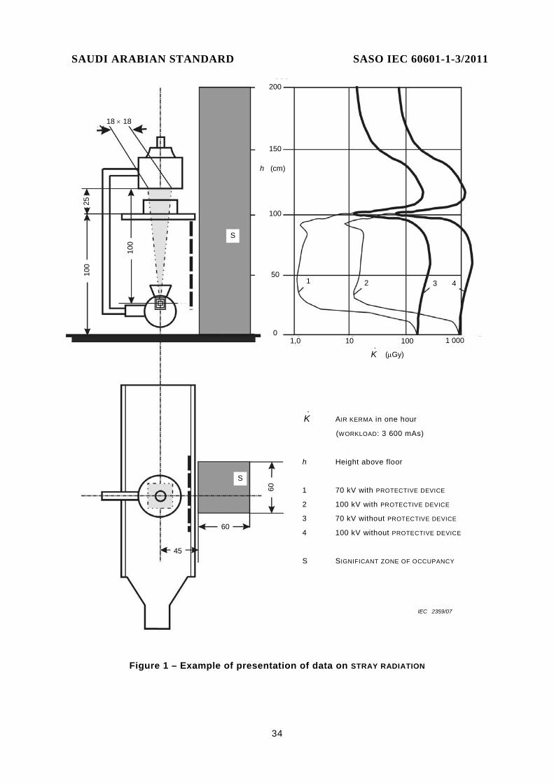
SAUDI ARABIAN STANDARD SASO IEC 60601-1-3/2011
34
K& AIR KERMA in one hour
(WORKLOAD: 3 600 mAs)
h Height above floor
1 70 kV with PROTECTIVE DEVICE
2 100 kV with PROTECTIVE DEVICE
3 70 kV without PROTECTIVE DEVICE
4 100 kV without PROTECTIVE DEVICE
S SIGNIFICANT ZONE OF OCCUPANCY
100
100
25
18 × 18
200
150
100
50
0
h (cm)
K& (µGy)
1,0 10 100 1 000
1 2 3 4
S
S
60
60
45
IEC 2359/07
Figure 1 – Example of presentation of data on STRAY RADIATION

SAUDI ARABIAN STANDARD SASO IEC 60601-1-3/2011
35
Annex A (informative)
General guidance and rationale
A.1 General guidance
This annex provides a concise rationale for the important requirements of this collateral standard. Its purpose is to promote effective application of the collateral standard by explaining the reasons for the requirements and provide additional guidance where appropriate.
A.2 Rationale for particular clauses and subclauses
The following are rationales for specific clauses and subclauses in this collateral standard, with clause and subclause numbers parallel to those in the body of the document.
Subclause 5.2.4.5 – Deterministic effects (ICRP60) [17]
Deterministic effects may occur when the RADIATION dose to a certain organ or tissue exceeds a specific threshold. Particular organs or tissues of such concern in diagnostic RADIOLOGY are the skin and the eye lens. The numerical value of the threshold dose is in the range between 1 Gy and 3 Gy.
Subclause 8.5.2 – FOCAL SPOT TO IMAGE RECEPTOR DISTANCE
The permissible non-reproducibility of the FOCAL SPOT TO IMAGE RECEPTOR DISTANCE and its permissible non-linearity over an indicated range are constrained by the need to comply with other requirements for the dimensions of the X-RAY FIELD and its correspondence with the IMAGE RECEPTION AREA, since these are tested, when relevant, at indicated settings of the FOCAL SPOT TO IMAGE RECEPTOR DISTANCE.
Clause 12 – Protection against LEAKAGE RADIATION
This collateral Standard uses the quantity AIR KERMA for all purposes. For some situations, e.g. LEAKAGE RADIATION and STRAY RADIATION in SIGNIFICANT ZONES OF OCCUPANCY, the AMBIENT DOSE EQUIVALENT would seem to be more appropriate since this quantity is more directly related with the effective dose. However, it was decided here to use only the quantity AIR KERMA in view of the potential for confusion arising from reference to two different quantities, and because the measurement of the AMBIENT DOSE EQUIVALENT is more complicated. It can also be noted that the numerical values of these two quantities differ only by factors of between 1 and 1,7 for the relevant x-ray energies, and estimates of the AMBIENT DOSE EQUIVALENT can be made with sufficient accuracy based on the IRRADIATION conditions and measured AIR KERMA values.
Subclause 13.4 – Designated SIGNIFICANT ZONES OF OCCUPANCY
In RADIOLOGICAL examinations needing the OPERATOR or staff to be close to the PATIENT during LOADING, a significant contribution to the total STRAY RADIATION encountered by these persons is often made by SCATTERED RADIATION from the PATIENT and other objects in the X-RAY BEAM. The scope for providing effective protection against this is limited by the need to avoid restricting unduly the conduct of the diagnostic procedures concerned.

SAUDI ARABIAN STANDARD SASO IEC 60601-1-3/2011
36
Knowledge of the levels of STRAY RADIATION in SIGNIFICANT ZONES OF OCCUPANCY is highly relevant in determining safe working practices. In this clause, recommendations are made for the determination and presentation of information about the levels of STRAY RADIATION.
Subclause 13.6 – Test for STRAY RADIATION
The basic method of test shall be to make measurements of AIR KERMA RATE in the SIGNIFICANT ZONE OF OCCUPANCY, using an appropriate PHANTOM to represent the presence of a PATIENT. These measurements are made at appropriate values of X-RAY TUBE VOLTAGE for which the information is to be stated and at convenient values of X-RAY TUBE CURRENT, or CURRENT TIME PRODUCT, within the ratings of the X-RAY SOURCE ASSEMBLY concerned. The measurements are then normalized to a CURRENT TIME PRODUCT representing a WORKLOAD in a period of one hour, and stated in terms of the AIR KERMA in that period, as a function of the height above the floor. Guidance is given concerning suitable test arrangements and parameters.
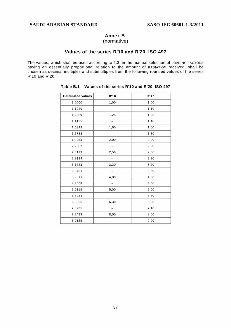
SAUDI ARABIAN STANDARD SASO IEC 60601-1-3/2011
37
Annex B (normative)
Values of the series R'10 and R'20, ISO 497
The values, which shall be used according to 6.3, in the manual selection of LOADING FACTORS having an essentially proportional relation to the amount of RADIATION received, shall be chosen as decimal multiples and submultiples from the following rounded values of the series R′10 and R′20.
Table B.1 – Values of the series R'10 and R'20, ISO 497
Calculated values R′10 R′20
1,0000 1,00 1,00
1,1220 – 1,10
1,2589 1,25 1,25
1,4125 – 1,40
1,5849 1,60 1,60
1,7783 – 1,80
1,9953 2,00 2,00
2,2387 – 2,20
2,5119 2,50 2,50
2,8184 – 2,80
3,1623 3,20 3,20
3,5481 – 3,60
3,9811 4,00 4,00
4,4668 – 4,50
5,0119 5,00 5,00
5,6234 – 5,60
6,3096 6,30 6,30
7,0795 – 7,10
7,9433 8,00 8,00
8,9125 – 9,00

SAUDI ARABIAN STANDARD SASO IEC 60601-1-3/2011
38
Annex C (informative)
Mapping between this Edition 2 of IEC 60601-1-3 and Edition 1
Edition 2 Edition 1 Title
Foreword 2.204 Degrees of requirements and miscellaneous terms
1 1 Scope, object and related standards
1.1 1.201 Scope
1.2 1.202 Object
1.3 1.203 Relationship to other standards
2 n.a. Normative references
3 2 Terms and definitions
Part of 3 2.205 RADIATION QUANTITIES and units
4 n.a. General requirements
4.1 4.201.1 Statement of compliance
4.2 2.203 Composition of reference materials
5 6 ME EQUIPMENT identification, marking and documents
5.1 6.1 Marking on the outside of ME EQUIPMENT or ME EQUIPMENT parts
5.1.1 6.1.202 General
5.1.2 6.1.201 Marking requirements in subclauses
5.2 6.8 ACCOMPANYING DOCUMENTS
5.2.1 6.8.201 References in subclauses
5.2.2 n.a. Dosimetric calibration
5.2.3 6.8.202 General requirements for the reference of subassemblies and ACCESSORIES
5.2.4 n.a. Instructions for use
6 n.a. RADIATION management
6.1 NOTE General
6.2 n.a. Initiation and termination of the IRRADIATION
6.3 n.a. RADIATION dose and RADIATION QUALITY
6.4 n.a. Indication of operational states
6.5 n.a. AUTOMATIC CONTROL SYSTEM
6.6 n.a. SCATTERED RADIATION reduction
6.7 n.a. Imaging performance
7 29.201 RADIATION QUALITY
7.1 29.201.2 and 29.201.5
HALF-VALUE LAYERS and TOTAL FILTRATION in X-RAY EQUIPMENT
7.2 n.a. Waveform of the X-RAY TUBE VOLTAGE
7.3 29.201.6 Indication of FILTER properties
7.4 29.201.7 Test for FILTRATION by irremovable materials
7.5 29.201.8 Test for ADDED FILTERS and materials
7.6 29.201.9 Test for HALF-VALUE LAYER
8 29.202 Limitation of the extent of the X-RAY BEAM and relationship between X-RAY FIELD and IMAGE RECEPTION AREA
8.1 Note General
8.2 29.202.1 Enclosure of X-RAY TUBES

SAUDI ARABIAN STANDARD SASO IEC 60601-1-3/2011
39
Edition 2 Edition 1 Title
8.3 29.202.2 Limiting DIAPHRAGM in X-RAY TUBE ASSEMBLIES
8.4 29.202.3 Confinement of EXTRA-FOCAL RADIATION
8.5 29.203 Relationship between X-RAY FIELD and IMAGE RECEPTION AREA
8.5.1 Note General
8.5.2 29.203.2 FOCAL SPOT TO IMAGE RECEPTOR DISTANCE
8.5.3 29.203.4 Correspondence between X-RAY FIELD and IMAGE RECEPTION AREA
8.5.4 n.a. Positioning of the PATIENT and restriction of the irradiated area
9 29.205 FOCAL SPOT TO SKIN DISTANCE
9.1 Note General
9.2 29.205.3 Information in the ACCOMPANYING DOCUMENTS
10 29.206 ATTENUATION of the X-RAY BEAM between the PATIENT and the X-RAY IMAGE RECEPTOR
10.1 Note General
10.2 29.206.2 Information in the ACCOMPANYING DOCUMENTS
11 29.207 Protection against RESIDUAL RADIATION
12 29.204 Protection against LEAKAGE RADIATION
12.1 Note General
12.2 29.204.1 Mounting of X-RAY SOURCE ASSEMBLIES and X-RAY IMAGING ARRANGEMENTS
12.3 29.204.2 Statement of reference LOADING conditions
12.4 29.204.3 LEAKAGE RADIATION in the LOADING STATE 12.5 29.204.5 LEAKAGE RADIATION when not in the LOADING STATE
13 29.208 Protection against STRAY RADIATION
13.1 Note General
13.2 29.208.2 Control from a PROTECTED AREA
13.3 29.208.1 Protection by distance
13.4 29.208.3 Designated SIGNIFICANT ZONES OF OCCUPANCY
13.5 29.208.5 Handgrips and control devices
13.6 29.208.6 Test for STRAY RADIATION
n.a. Annex CCC Normative references to ACCOMPANYING DOCUMENTS, instructions for use and ASSEMBLING INSTRUCTIONS
Annex A n.a. General guidance and rationale
Annex B n.a. Values of the series R'10 and R'20, ISO 497
Annex C n.a. Mapping between this Edition 2 of IEC 60601-1-3 and the Edition1
n.a. Bibliography

SAUDI ARABIAN STANDARD SASO IEC 60601-1-3/2011
40
Bibliography
IEC under http://www.iec.ch/
ISO under http://www.iso.ch/iso/en/ISOOnline.frontpage
[1] IEC 60601-2-7:1998, Medical electrical equipment – Part 2-7: Particular requirements for the safety of high-voltage generators of diagnostic X-ray generators
[2] IEC 60601-2-28:1993, Medical electrical equipment – Part 2: Particular requirements for the safety of X-ray source assemblies and X-ray tube assemblies for medical diagnosis
[3] IEC 60601-2-29:1999, Medical electrical equipment – Part 2-29: Particular requirements for the safety of radiotherapy simulators
[4] IEC 60601-2-32:1994, Medical electrical equipment – Part 2: Particular requirements for the safety of associated equipment of X-ray equipment
[5] IEC 60601-2-43:2000, Medical electrical equipment – Part 2-43: Particular requirements for the safety of X-ray equipment for interventional procedures
[6] IEC 60601-2-44:2001, Medical electrical equipment – Part 2-44: Particular requirements for the safety of X-ray equipment for computed tomography1) Amendment 1 (2002)
[7] IEC 60601-2-45:2001, Medical electrical equipment – Part 2-45: Particular requirements for the safety of mammographic X-ray equipment and mammographic stereotactic devices
[8] IEC 60580:2000, Medical electrical equipment – Dose area product meters
[9] IEC 60627:2001, Diagnostic X-ray imaging equipment – Characteristics of general purpose and mammographic anti-scatter grids
[10] IEC 60878, Graphical symbols for electrical equipment in medical practice
[11] IEC 61262 (all parts), Medical electrical equipment – Characteristics of electro-optical X-ray image intensifiers
[12] IEC 62220 (all parts), Medical electrical equipment – Characteristics of digital X-ray imaging devices
[13] IEC 62220-1:2003, Medical electrical equipment – Characteristics of digital X-ray imaging devices – Determination of the detective quantum efficiency
[14] ISO 7004:2002, Photography – Industrial radiographic films – Determination of ISO speed, ISO average gradient and ISO gradients G2 and G4 when exposed to X- and gamma-radiation
[15] ICRP Publication 33: Protection against ionizing radiation from external sources used in medicine (Annals of the ICRP Vol. 9 No. 1, 1982). Published by Pergamon Press
————————— 1) A consolidated edition 2.1 exists, including IEC 60601-2-44:2001 and its Amendment 1 (2002).

SAUDI ARABIAN STANDARD SASO IEC 60601-1-3/2011
41
[16] ICRP Publication 34: Protection of the patient in diagnostic radiology (Annals of the ICRP Vol. 9 No. 213, 1982). Published by Pergamon Press
[17] ICRP Publication 60:1990 Recommendations of the International Commission on Radiological Protection (Annals of the ICRP Vol. 21 No. 1-3, 1991). Published by Pergamon Press
[18] ICRP Publication 73: Radiological protection and safety in medicine (Annals of the ICRP Vol. 26 No. 2, 1996). Published by Pergamon Press
[19] ICRU Report 51: Quantities and Units in Radiation Protection Dosimetry (1993)
[20] ICRU Report 60: Fundamental Quantities and Units for Ionizing Radiation (1998)
[21] ICRP Publication 85: Avoidance of Radiation Injuries from Medical Interventional Procedures (Annals of the ICRP Vol 30 No.2, 2000) Published by Pergamon Press
[22] ICRP Publication 87: Managing Patient Dose in Computed Tomography. (Annals of the ICRP Vol 30 No.4, 2000) Published by Pergamon Press
[23] ICRP Publication 93: Managing Dose in Digital Radiology. (Annals of the ICRP Vol 34 No.1, 2004) Published by Elsevier
[24] ICRU Report 74: Patient dosimetry for x-rays used in medical imaging (2005), Published by Oxford University Press, Oxford

SAUDI ARABIAN STANDARD SASO IEC 60601-1-3/2011
42
Index of defined terms used in this collateral standard
Defined term Defined in ABSORBED DOSE IEC 60788:2004, rm-13-08 ABSORPTION IEC 60788:2004, rm-12-05 ACCESSIBLE SURFACE 3.1 ACCOMPANYING DOCUMENTS IEC 60601-1:2005, 3.4 ACTUAL FOCAL SPOT IEC 60788:2004, rm-20-12 ADDED FILTER 3.2 ADDITIONAL FILTRATION 3.3 AIR KERMA 3.4 AIR KERMA RATE 3.5 ACCESSORY IEC 60601-1:2005, 3.3 AMBIENT DOSE EQUIVALENT 3.6 ANODE IEC 60788:2004, rm-22-06 ANODE INPUT POWER IEC 60788:2004, rm-36-22 ASSOCIATED EQUIPMENT IEC 60788:2004, rm-30-01 ATTENUATION 3.7 ATTENUATION EQUIVALENT 3.8 AUTOMATIC CONTROL SYSTEM 3.9 AUTOMATIC EXPOSURE CONTROL 3.10 BASIC SAFETY IEC 60601-1:2005, 3.10 BEAM LIMITING DEVICE 3.11 BEAM LIMITING SYSTEM 3.12 CATHODE IEC 60788:2004, rm-22-05 CONTINUOUS ANODE INPUT POWER 3.13 CONTROL PANEL 3.14 CONTROLLED AREA 3.15 CORRECTION FACTOR IEC 60788:2004, rm-73-14 CURRENT TIME PRODUCT 3.16 DIAPHRAGM 3.17 DIGITAL X-RAY IMAGING DEVICE IEC 62220-1:2003, 3.5 DOSE AREA PRODUCT IEC 60788:2004, rm-13-54 DOSE EQUIVALENT 3.18 EDGE FILTER 3.19 EFFECTIVE FOCAL SPOT IEC 60788:2004, rm-20-13 EFFECTIVE IMAGE RECEPTION AREA 3.20 ELECTRON IEC 60788:2004, rm-11-18 ENTRANCE SURFACE 3.21 EQUIPMENT IEC 60601-1:2005, 3.63 ESSENTIAL PERFORMANCE IEC 60601-1:2005, 3.27 EXTRA-FOCAL RADIATION 3.22 FILTER 3.23

SAUDI ARABIAN STANDARD SASO IEC 60601-1-3/2011
43
Defined term Defined in FILTRATION 3.24 FOCAL SPOT IEC 60788:2004, rm-20-13s FOCAL SPOT TO IMAGE RECEPTOR DISTANCE 3.25 FOCAL SPOT TO SKIN DISTANCE 3.26 HALF-VALUE LAYER 3.27 HIGH-VOLTAGE GENERATOR IEC 60788:2004, rm-21-01 IMAGE DISPLAY DEVICE IEC 60788:2004, rm-80-08 IMAGE RECEPTION AREA 3.28 INDICATED VALUE IEC 60788:2004, rm-73-10 INTENDED USE IEC 60601-1:2005, 3.44 IONIZING RADIATION 3.29 IRRADIATION 3.30 IRRADIATION SWITCH 3.31 IRRADIATION TIME 3.32 LEAKAGE RADIATION 3.33 LOADING 3.34 LOADING FACTOR 3.35 LOADING STATE 3.36 LOADING TIME 3.37 MANUFACTURER IEC 60601-1:2005, 3.55 MEASURED VALUE 3.38 MEDICAL DIAGNOSTIC RADIOLOGY IEC 60788:2004, rm-40-04 MEDICAL ELECTRICAL EQUIPMENT (ME EQUIPMENT) IEC 60601-1:2005, 3.63 MEDICAL ELECTRICAL SYSTEM (ME SYSTEM) IEC 60601-1:2005, 3.64 MEDICAL RADIOLOGY 3.39 MODE OF OPERATION 3.40 NARROW BEAM IEC 60788:2004, rm-37-22 NARROW BEAM CONDITION 3.41 NOMINAL X-RAY TUBE VOLTAGE 3.42 NORMAL USE IEC 60601-1:2005, 3.71 OPERATOR IEC 60601-1:2005, 3.73 PATIENT IEC 60601-1:2005, 3.76 PATIENT ENTRANCE REFERENCE POINT 3.43 PERCENTAGE RIPPLE 3.44 PERMANENT FILTRATION 3.45 PHANTOM 3.46 POINT SOURCE IEC 60788:2004, rm-34-36 PRIMARY PROTECTIVE SHIELDING 3.47 PROTECTED AREA 3.48 PROTECTIVE BARRIER 3.49 PROTECTIVE CLOTHING 3.50 PROTECTIVE DEVICE 3.50 PROTECTIVE SHIELDING 3.51 QUALITY EQUIVALENT FILTRATION 3.52

SAUDI ARABIAN STANDARD SASO IEC 60601-1-3/2011
44
Defined term Defined in RADIATION 3.53 RADIATION APERTURE 3.54 RADIATION BEAM 3.55 RADIATION CONDITION 3.56 RADIATION DETECTOR 3.57 RADITAION ENERGY IEC 60788:2004, rm-13-29 RADIATION FIELD 3.58 RADIATION PROTECTION 3.59 RADIATION QUALITY 3.60 RADIATION QUANTITY IEC 60788:2004, rm-13-01 RADIATION SOURCE 3.61 RADIATION SOURCE ASSEMBLY 3.62 RADIOGRAPHIC RATING 3.63 RADIOGRAPHY 3.64 RADIOLOGICAL 3.65 RADIOLOGICAL IMAGE 3.66 RADIOLOGICAL INSTALLATION 3.67 RADIOLOGY 3.68 RADIOSCOPY 3.69 READY STATE IEC 60788:2004, rm-84-05 REFERENCE AIR KERMA 3.70 REFERENCE AIR KERMA RATE 3.71 REFERENCE AXIS IEC 60788:2004, rm-37-03 REFERENCE DIRECTION IEC 60788:2004 REFERENCE PLANE IEC 60788:2004, rm-37-04 RESIDUAL RADIATION 3.72 RESPONSIBLE ORGANIZATION IEC 60601-1:2005, 3.101 RISK IEC 60601-1:2005, 3.102 RISK MANAGEMENT IEC 60601-1:2005, 3.107 RISK MANAGEMENT FILE IEC 60601-1:2005, 3.108 SCATTERED RADIATION 3.73 SIGNIFICANT ZONE OF OCCUPANCY 3.74 SINGLE FAULT CONDITION IEC 60601-1:2005, 3.116 STRAY RADIATION 3.75 STRUCTURAL SHIELDING 3.76 TARGET IEC 60788:2004, rm-20-08 TOTAL FILTRATION 3.77 TRANSFER IEC 60788:2004, rm-84-02 TRUE VALUE IEC 60788:2004, rm-73-07 TYPE TEST IEC 60601-1:2005, 3.135 WORKLOAD IEC 60788:2004, rm-61-03 X-RADIATION 3.53 X-RAY BEAM 3.55 X-RAY BEAM AXIS IEC 60788:2004, rm-37-06

SAUDI ARABIAN STANDARD SASO IEC 60601-1-3/2011
45
Defined term Defined in X-RAY EQUIPMENT 3.78 X-RAY FIELD 3.58 X-RAY GENERATOR 3.79 X-RAY IMAGING ARRANGEMENT 3.80 X-RAY IMAGE RECEPTOR 3.81 X-RAY PATTERN 3.82 X-RAY SOURCE ASSEMBLY 3.62 X-RAY TUBE 3.83 X-RAY TUBE ASSEMBLY 3.84 X-RAY TUBE CURRENT 3.85 X-RAY TUBE HOUSING 3.86 X-RAY TUBE LOAD 3.87 X-RAY TUBE VOLTAGE 3.88
___________