save money up front… and over the life of the equipment
TRANSCRIPT

451-
110
LIFELIGN® COUPLINGSSave money up front…
and over the life of the equipment
T
HE
F
AL
KC
O
RP
OR
AT
IO
N

FALK LIFELIGN® COUPLINGSRealize life-long savings
Initial savingsFalk Lifelign couplings provide theeconomies budget-minded usersseek, without sacrificing couplingquality or reliability.
Superior bore capacities and torque ratings
The unmatched bore capacities andtorque ratings of Falk Lifeligncouplings often allow you to select asmaller sized coupling for a givenapplication.
In fact, selections for T frame, 60 hertz electric motors result in a drop of one coupling size for half of the 28 motor frames available. The result: genuine Falk quality, reliability and performance with average savings of 15-20% over competitive offerings.
The smaller overall size also makes Lifelign couplings well suited for limited space applications that still require large bores and high torque loads.
Ideal for existing applications
Half for half interchangeability allows you to add capacity and realize the advantages of Lifelign couplings on your existing applications and designs, as well.
What’s more, Lifelign’s larger hub diameter features more metal over the keyway versus other designs,providing greater reserve strength against hub fractures due to shock or impact loads.
• High-strength Grade 8 Bolts provide addedprotection against failure
• Lube holes located near the tooth mesh to ensure anadequate grease reservoir during initial startup
• Massive Flex Hub provides the industry’s largest bore capacityfor the most economical selection possible
Non-turning prevailing torque locknut provides a reliablehold with fewer parts •
• 4-Point seal improves lubrication retention during misalignment;high-temperature seals are available
• AGMA bolt pattern makes Lifelign easily interchangeablewith any standard coupling on your existing applications
AGMA 20° full-depth tooth triple crowning eliminates tiploading, and reduces backlash and radial clearances •

Designs to meet adiverse range of needsG Standard FlangedSleeve
General purposeseries used on bulkhandling systems,paper machines,fans, pumps, cranesmixers, sugar mills,crushers and manyother high-torqueapplications.
GC ContinuousSleeve
Used on high-speed equipmentwith low inertiarequirements.
G Large FlangedSleeve
For very hightorque applications,including powerplants, mining,cement, steel andmetal mills, paper,sugar, rubberand other large indus-trial plants.
G10 Shrouded Bolt
AGMACouplingSize
111⁄2221⁄2331⁄2441⁄2551⁄267
PopularCompetitiveBrands
1.6252.2502.7503.5004.0004.5005.5006.0006.6257.5008.1259.625
FalkLIFELIGNCouplings
1.8752.3752.8753.6254.1254.8755.7506.7507.3758.2509.125
10.875
Greater bore capacity
AGMACouplingSize
111⁄2221⁄2331⁄2441⁄2551⁄267
PopularCompetitiveBrands
7,50018,90031,50056,70094,500
151,200220,500302,400434,700573,300749,700
1,008,000
FalkLIFELIGNCouplings
10,08020,79037,80066,150
107,100163,800270,900371,700500,900655,200800,100
1,197,000
Higher torque ratings

Lifetime savingsLifelign Couplings are speciallydesigned to remain your mosteconomical solution by extendingmaintenance intervals, reducingwear and increasing service life.
Advanced lube system
Falk Long Term Grease (LTG)eliminates routine lubrication cyclesfor up to 3 years. The location of thelubrication hole in the sleeve ensuresthat an adequate grease reservoirwill be maintained close to the gearmesh. Plus, Lifelign’s 4-point sealcontact provides better retention oflubricant, eliminating the axial sealmovement that can draw lubricantout of the coupling shouldmisalignment occur.
For added reliability our standardseals handle a maximum continuousoperating temperature of 250°F(121°C) and a maximum intermittenttemperature of 300°F (149°C). Hightemperature seals are available,extending maximum temperatures to 400°F(204°C) for continuousduty and 500°F (260°C)for inter-mittentuse.
Triplecrown protection
Crowning at the root, tip and face ofeach tooth helps minimize weardamage due to misalignment. Thistriple-crown effect eliminates tiploading, while also reducingbacklash and radial clearances.
Reliable, convenient fasteners
High-strength, Grade-8 fastenersprovide added protection againstcoupling failure at the flange joint. Toassure the easiest possibleassembly and disassembly, fastenersare zinc-coated to prevent corrosionand feature non-turning locknuts,which allowone-wrenchinstallationwith nowashersrequired.
You get more thancost savings with Falk Lifelign couplingsCapacity
Falk supplies the largest gearcouplings in the world for low-speed,high-torque applications or wherebore capacities of 10” to 52” arerequired.
Quality
Falk pours its own castings andcompletely machines thecomponents to assure maximumproduct integrity with minimum leadtimes.
Performance
Falk can supply alloy steels forhydraulic hub removal, increasedwear resistance, or to increase torqueratings by an average of 60% foronly about a 30% increase in price.The torque boost can allow smallersizes to be used, thus significantlyreducing overall costs.
Selection
Falk supplies a complete range ofcoupling designs including, gear disc,grid, elastomer and fluid couplings
Expertise
Falk’s extensive applicationsengineering expertise combines withour comprehensive product offeringto assure that you wind up with thebest choice for the job…. and yourpreferred requirements.
Packaged system design
Falk’s unmatched variety of geardrives allows us to develop completepackaged systems for your powertransmission needs. In many cases,pre-packaged systems offer drop-ininstallation or replacement, minimiz-ing installation time and costs.
Global availability and support
Falk has 900+ distributor locationsand 80+ sales engineers, offeringlocal availability on a global basis
3-Year Heavy-Duty Warranty
Falk rewrote industry expectationsby offering the first 3-Year Warranty,standard, on all “heavy-duty”products.
Online support
Falk’s online support includes sparesinformation and pricing, service data,product literature, quoting tools andengineering artwork.
Falk Other

© The Falk Corporation, 1992, 2003. (451-110) 5
Table of ContentsNomenclature . . . . . . . . . . . . . . . . . . . . . . . . . . . . . . . . . . . . . . . . . . 6Available Types . . . . . . . . . . . . . . . . . . . . . . . . . . . . . . . . . . . . . . . 7-9How to Select . . . . . . . . . . . . . . . . . . . . . . . . . . . . . . . . . . . . . . 10-11Service Factors. . . . . . . . . . . . . . . . . . . . . . . . . . . . . . . . . . . . . . 12-13How to Order . . . . . . . . . . . . . . . . . . . . . . . . . . . . . . . . . . . . . . . . . 13
CONTINUOUS SLEEVE GEAR COUPLINGS —Dimensions & SpecificationsType GC02 Double Engagement . . . . . . . . . . . . . . . . . . . . . . . . . . . 14Type GC05 Single Engagement . . . . . . . . . . . . . . . . . . . . . . . . . . . . 15Type GC05 Floating Shaft . . . . . . . . . . . . . . . . . . . . . . . . . . . . . . . . 16STANDARD FLANGED SLEEVE GEAR COUPLINGS —Dimensions & SpecificationsType G20 Double Engagement . . . . . . . . . . . . . . . . . . . . . . . . . . . . 17Type G32 Spacer . . . . . . . . . . . . . . . . . . . . . . . . . . . . . . . . . . . . . . 18Type G52 Single Engagement . . . . . . . . . . . . . . . . . . . . . . . . . . . . . 19Type G52 Floating Shaft. . . . . . . . . . . . . . . . . . . . . . . . . . . . . . . 20-21Type GV20 Vertical Double Engagement . . . . . . . . . . . . . . . . . . . . . 22Type GV52 Vertical Single Engagement . . . . . . . . . . . . . . . . . . . . . . 23Types G62/G66 Brakewheel, Straight Bores & G63 Disc Brake . . . . . 24Types G62 & G66 Brakewheel, Taper Bores . . . . . . . . . . . . . . . . . . . 25Type GL20 Slide Double Engagement . . . . . . . . . . . . . . . . . . . . . . . 26Type GL52 Slide Single Engagement . . . . . . . . . . . . . . . . . . . . . . . . 27Type G70 Disconnect, Inching Drives . . . . . . . . . . . . . . . . . . . . . . . . 28Type G72 Disconnect . . . . . . . . . . . . . . . . . . . . . . . . . . . . . . . . . . . 29Type GP20/52/82 Insulated . . . . . . . . . . . . . . . . . . . . . . . . . . . . . . 30Type G82 Rigid . . . . . . . . . . . . . . . . . . . . . . . . . . . . . . . . . . . . . . . 31Type GV82 Rigid Thrust . . . . . . . . . . . . . . . . . . . . . . . . . . . . . . . . . 32Type GR20 Shear Pin . . . . . . . . . . . . . . . . . . . . . . . . . . . . . . . . . . . 33Type G Mill Motor & Taper Bores . . . . . . . . . . . . . . . . . . . . . . . . . . 34Engineering DataRecommended Commercial Keys for Bores With One Key . . . . . . . . 35Shaft Diameters & Ratings for NEMA 60 Hertz & 50 HertzMetric Motors . . . . . . . . . . . . . . . . . . . . . . . . . . . . . . . . . . . . . . . . . 35Maximum Bores . . . . . . . . . . . . . . . . . . . . . . . . . . . . . . . . . . . . . . . 36Recommended Bore Tolerances, Falk Steel Coupling Hubs . . . . . . . . 36Flanged Sleeve & Rigid Hub Details . . . . . . . . . . . . . . . . . . . . . . . . . 37Puller Bolt Holes . . . . . . . . . . . . . . . . . . . . . . . . . . . . . . . . . . . . . . . 37Torsional Stiffness . . . . . . . . . . . . . . . . . . . . . . . . . . . . . . . . . . . . . . 38WR2 Values. . . . . . . . . . . . . . . . . . . . . . . . . . . . . . . . . . . . . . . . . . . 38Standard Filleted Keyways & Chamfered Keys . . . . . . . . . . . . . . . . . . 38Variable Gap . . . . . . . . . . . . . . . . . . . . . . . . . . . . . . . . . . . . . . . . . 39Misalignment Capacity . . . . . . . . . . . . . . . . . . . . . . . . . . . . . . . . . . 39
LARGE FLANGED SLEEVE GEAR COUPLINGS —Dimensions & SpecificationsType G20 Double Engagement . . . . . . . . . . . . . . . . . . . . . . . . . . . . 40Type G52 Single Engagement . . . . . . . . . . . . . . . . . . . . . . . . . . . . . 41Type G52 Floating Shaft . . . . . . . . . . . . . . . . . . . . . . . . . . . . . . . . . 42Type GV20 Vertical Double Engagement . . . . . . . . . . . . . . . . . . . . . 43Type GV52 Vertical Single Engagement . . . . . . . . . . . . . . . . . . . . . . 44Type GL20-4 Slide Double Engagement . . . . . . . . . . . . . . . . . . . . . . 45Type G70 Disconnect, Inching Drives . . . . . . . . . . . . . . . . . . . . . . . . 46Type G82 Rigid . . . . . . . . . . . . . . . . . . . . . . . . . . . . . . . . . . . . . . . 47Type GR20 Shear Pin. . . . . . . . . . . . . . . . . . . . . . . . . . . . . . . . . . . . 48
Engineering DataRecommended Commercial Keys for Bores withOne & Two Keys — Inches . . . . . . . . . . . . . . . . . . . . . . . . . . . . . . . 49Maximum Bores — Inches . . . . . . . . . . . . . . . . . . . . . . . . . . . . . . . . 50Recommended Bore Tolerances, Falk Steel Coupling Hubs . . . . . . . . 50Flanged Sleeve & Rigid Hub Details . . . . . . . . . . . . . . . . . . . . . . . . 51Sleeve Jack Bolt Holes. . . . . . . . . . . . . . . . . . . . . . . . . . . . . . . . . . . 51Puller Bolt Holes . . . . . . . . . . . . . . . . . . . . . . . . . . . . . . . . . . . . . . . 51Torsional Stiffness . . . . . . . . . . . . . . . . . . . . . . . . . . . . . . . . . . . . . . 51WR2 Values. . . . . . . . . . . . . . . . . . . . . . . . . . . . . . . . . . . . . . . . . . . 51Bore Ranges for Reduced Shank Dia. Hubs — Inches . . . . . . . . . . . . 52Puller Bolt Holes for Reduced Shank Dia. Hubs — Inches . . . . . . . . . 52Standard Filleted Keyways & Chamfered Keys . . . . . . . . . . . . . . . . . 53Misalignment Capacity . . . . . . . . . . . . . . . . . . . . . . . . . . . . . . . . . . 54
ALL TYPESRecommended Hub Bores for Interference & Clearance Fit . . . . . . . . 55Coupling Application Data Sheet . . . . . . . . . . . . . . . . . . . . . . . . . . . 56Interchange Guide Flanged & Continuous Sleeve . . . . . . . . . . . . 57-58Headquarters & Global Sales Offices . . . . . . . . . . . . . . . . . . . . . . . . 60
Basic InformationInstall and operate Falk products in conformance with applicablelocal and national safety codes and per Falk installation manualswhich are available upon request. Suitable guards for rotatingmembers may be purchased from Falk as optional accessories.Consult your local Falk Representative for complete details.
WARNING: Lock out power and remove all external loads fromthe system before attempting to service any component in thesystem. Locking out the power and removing the load will reducethe possibility of unexpected motion or reaction in the system.
Falk Long Term Grease Benefits include: increased couplinglife, significantly extended relubrication intervals, reducedmaintenance costs, reduced downtime, superior lubrication, highload carrying capabilities and it is usable up to 250°F (121°C).
For information on Falk Long Term Grease, requestForm 840201B. Lifelign gear couplings are warranted for 3 yearswhen lubricated with Falk LTG Long Term Grease.
Selection Guide 451-110, January 2003
Copyright 1992, 2003, The Falk Corporation. All Rights Reserved. Litho in U.S.A.FALK, A-PLUS, LIFELIGN, OMNIBOX, RAM, RENEW, STEELFLEX, and ULTRAMITEare registered trademarks. Magnum Seal is a trademark of The Falk Corporationfor its rotary shaft sealing system for enclosed gear drives. Taper-Lock is aregistered trademark of a bushing under license. Viton is a registered trademark ofthe DuPont Co..The contents of this selection guide are subject to change without notice orobligation. Information contained herein should be confirmed before placing orders.
� Warranty extends for 3 years from date of shipment. Does not apply to FalkOmnibox, Ultramite, Fluid Couplings, Renew and spare parts. Warranty applies toSteelflex and Lifelign couplings with the use of Falk Long Term grease.
Falk Factory Warranty We’re so confident in the performanceand reliability of our latest generation of Falk heavy-duty productsthat we’re backing this comprehensive offering with the beststandard warranty in the business. Our full, 3-year Heavy-DutyWarranty provides “shaft-to-shaft” protection on all Falkcomponents – including bearings and seals. It’s an industry first...and one more powerful reason why Falk is your ultimatebottom-line drive and coupling value.� Lifelign couplings arewarranted for 3 years when lubricated with Falk LTG Long TermGrease

6 (451-110) © The Falk Corporation, 1992, 2003.
F A L K
Lifelign® Gear Coupling NomenclatureType GC (Pages 14 thru 16 & 35 thru 39)
1010 GC 02
SIZE PRODUCT TYPECLASSIFICATION
Gear — Continuous Sleeve GC02 = Double EngagementGC05 = Single Engagement/Floating Shaft
Type G (Pages 15 thru 37)
1010 G 20
SIZE PRODUCT TYPE (Shrouded and Exposed Bolts)CLASSIFICATION
Gear — Standard Flanged Sleeve G10/20 = Double Engagement (Shrouded/Exposed)G51/52 = Single Engagement/Floating Shaft (Shrouded/Exposed)GV10/20 = Vertical Double Engagement (Shrouded/Exposed)GV51/52 = Vert. Single Engage./Floating Shaft (Shrouded/Exposed)G62 = Brakewheel Double Engagement (Exposed)G63 = Disc Brake Double Engagement (Exposed)G66 = Brakewheel Single Engagement (Exposed)GL20 = Slide Double Engagement (Exposed)GL52 = Slide Single Engagement/Floating Shaft (Exposed)G70 = Disconnect Inching DrivesG72 = Disconnect (Exposed)G31/32 = Spacer (Shrouded/Exposed)GP20 = Insulated Double Engagement (Exposed)GP52 = Insulated Single Engagement/Floating Shaft (Exposed)GP82 = Insulated Rigid (Exposed)G81/82 = Rigid (Shrouded/Exposed)GV82 = Vertical Rigid (Exposed)GR20 = Shear Pin (Exposed)
Type G (Pages 49 thru 63)
1080 G 20
SIZE PRODUCT TYPE (Exposed Bolts Only)CLASSIFICATION
Gear — Large Flanged Sleeve Type G20 = Double EngagementType G52 = Single Engagement/Floating ShaftType GV20= Vertical Double EngagementType GV52= Vertical Single Engagement//Floating ShaftType GL20 = Slide Double EngagementType G70 = Disconnect/Inching DrivesType G32 = SpacerType G82 = RigidType GV82= Vertical RigidType GR20= Shear Pin

© The Falk Corporation, 1992, 2003. (451-110) 7
Type GC02 & GC05
With two hubs and one sleeve, the simplicity of this continuoussleeve coupling allows it to be easily adapted to a wide variety ofapplications. It’s very compact, low in rotating mass, and has alower initial cost than flanged types. (See Pages 14 & 15.)
Type GC05 Floating Shaft
Floating shaft assemblies are used when distance betweenequipment is too great for spacer couplings. A standard floatingshaft assembly consists of two standard single engagementcouplings and a connecting shaft. A floating shaft can eliminate theneed for additional bearing supports along spanning shafts becausethe shaft is supported by connected equipment through the singleengagement couplings. (See Page 16.)
The Type G20 double engagement, close coupled type has twoflex halves to accommodate both offset and angularmisalignment or a combination of the two, as well as end float. Itis ideal for all horizontal, close coupled applications includingfans, overhead cranes, conveyors, steel and paper millequipment. It is adaptable with limited end float kits for use onelectric motors, generators or any machines fitted with sleeve orstraight roller bearings. (See Page 17.)
Type GV20 vertical double engagement coupling is a standardhorizontal double engagement gear coupling modified toaccommodate the sleeve centering assembly. Recommended forinclinations over 10°. (See Page 22.)
Types G20, GV20
Spacer couplings for pump and compressor applications simplifyservicing connected equipment. Spacer couplings use a standarddouble engagement coupling with a spacer tube and anadditional set of fasteners. Stock spacer lengths for quickdelivery are available in the popular sizes. Special lengths arealso available. (See Page 18.)
Types G32
Lifelign Gear Coupling Types

8 (451-110) © The Falk Corporation, 1992, 2003.
F A L K
Floating shaft assemblies are used when distance betweenequipment is too great for spacer couplings. A standard floatingshaft assembly consists of two standard single engagementcouplings, two gap discs and a connecting shaft. A floating shaft caneliminate the need for additional bearing supports along spanningshafts because the shaft is supported by connected equipmentthrough the single engagement couplings. (See Pages 21 and 42.)When used with a vertical floating shaft on inclinations over 10°,the Type GV52 coupling is used as the lower coupling to supportthe shaft.
Flex Hubs on Floating Shaft (RFFR) — Assembly of the flex hubson the floating shaft allows for easier replacement and allows therigid hubs with greater bore capacity to be used on theconnected equipment shafts. This frequently means a smallercoupling size can be utilized.
Rigid Hubs on Floating Shaft (FRRF) — When the rigid hubs areon the floating shaft, shorter shaft spans can be accommodated,since no cover drawback is required.
Types G52, GV52
Double or single engagement brakewheel and disc brakecouplings are used for applications, such as cranes, hoists andconveyors. Brakewheel and disc brake couplings accommodatemisalignment between connected equipment and eliminate theneed for double shaft extensions on motors and gear drives forapplications requiring brakes. (See Pages 24 & 25.)
Types G62 & 66 Type G63
The Type G52 single engagement design is used with floatingshafts or three bearing drive trains. It has one flex half and onerigid half and only accepts angular misalignment. (See Page 19.)
The GV52 vertical single engagement gear coupling is astandard horizontal single engagement gear coupling modifiedto accommodate the sleeve centering assembly. It recommendedfor inclinations over 10°. Downward thrust capacity for Sizes1010 thru 1030GV52 is 10,000 lbs.; Sizes 1035 thru1070GV52 is 30,000 lbs. and Sizes 1080GV52 and larger is87,000 lbs. (See Pages 23 & 44.)
Types G52, GV52
Types GL20 & GL52
Double and single engagement Slide couplings are used forapplications requiring axial movement to accommodate thermalshaft expansion or adjustment. (See Pages 26 & 27.)

© The Falk Corporation, 1992, 2003. (451-110) 9
INSULATORPLATE
Types GP20, 52 & 82
Double, single or rigid engagement insulated couplings are usedto eliminate the flow of stray current from one shaft to anotherand to protect sensitive electrical equipment. They are notintended to withstand high potential currents, short circuits orstatic charges. Insulated couplings consist of standard hubs andsleeves, and utilize reduced diameter socket head cap screws.The insulator plate is made of a NEMA Grade LE phenolicmaterial and insulator bushings and washers are made of NEMAGrade G9 phenolic material. (See Page 30.)
Type G70 Disconnect couplings are used for low speed applicationsthat require quick disconnect of equipment or inching drives. It isused for occasional servicing or inspection of drive systemcomponents and is most commonly used on portable or stationaryinching drive systems where the driving end hub/sleeve combinationis mounted on the driving shaft on the incher for connecting ordisconnecting at standstill. (See Page 28.)
Type G72 Disconnect couplings were designed for higher speedapplications that require quick disconnect such as backup drives.When the long flex hub is mounted on the auxiliary driving shaft,the changeover is performed at standstill by engaging the freerunning hub. (See Page 29.)
Types G70 & G72
Rigid couplings are used when there is no need to accommodatemisalignment, and where thrust loads are generated such asvertical mixer applications. (See Pages 31 and 32.)
The Type G Large Gear Coupling is available in all types forcapacities up to 72,450,00 lb-in., 8,185,000 Nm. (See Page 40.)
Type G82 & GV82 Type G Large Gear Coupling
SHEARPLATES
HARDENEDBUSHING
SHEAR PIN
SHEAR NOTCHDIAMETER
Shear pin couplings are used for applications subject to jammingand overload. When pins break, the equipment is physicallydisconnected preventing damage. If desired shear settings areunknown, the selection should be referred to Falk. (See Page 33.)
Type GR20

10 (451-110) © The Falk Corporation, 1992, 2003.
F A L K
How to SelectStandard Selection MethodThe standard selection method can be used for most motor,turbine, or engine driven applications. The following informationis required to select a gear coupling.
� Horsepower or torque
� Running rpm.
� Application or type of equipment to be connected (motor topump, drive to conveyor, etc.).
� Shaft diameters.
� Shaft gaps.
� Physical space limitations
� Special bore or finish information and type of fit
Exceptions are High Peak Loads, Brake Applications or highfrequency axial sliding (greater than 5 per hour). For theseconditions, use the Formula Selection Method on the nextpage. Applications that require rapid changes in directionor torque reversals should be referred to Falk.
1. RATING: Determine system torque. If torque is not given,calculate as shown below.
System Torque (lb - in) =HP x 63,000
rpm
Where: HP (Horsepower) is the actual or transmitted powerrequired by the application (if unknown, use the motor orturbine nameplate rating) and RPM is the actual speed thecoupling is rotating.
2. SERVICE FACTOR: Determine the appropriate service factorfrom Table 2 and 3, Page 12 or Table 4, Page 13.
3. REQUIRED MINIMUM COUPLING RATING: Determine therequired minimum coupling rating as shown below:
Minimum Coupling Rating = S.F. (Service Factor) x Torque(lb-in)
4. TYPE: Refer to Pages 7-9 and select the appropriate coupling type.
5. SIZE: Determine proper size of type selected from Table 1 bytracing down torque column to a value that is equal or greaterthan that determined in Step 3 above. Then turn to thedimension pages of appropriate coupling type selected andcheck the following for the size selected.
6. Check: Coupling Capacities and Dimensions
A. Bores — Check shaft diameters against coupling maximumbore. If bore is inadequate, consider the use of a reducedkey from engineering tables, or select a larger size coupling.
B. Speeds (rpm) — Check the operating rpm against thecoupling allowable speed. If catalogued values areinadequate, consider balancing. Balancing may allow up to50% increase in speeds shown. Contact Falk with completeapplication details.
C. Dimensions — Checks are: length of hubs and alignmentclearances against shaft lengths, outside diameter ofcoupling against radial clearances
STANDARD SELECTION EXAMPLE:
Select a gear coupling to connect a 500 HP, 1170 RPM electricmotor to a drive high speed shaft of a maneuvering winch.Maximum shaft separation is .250". Motor shaft diameter is3.375" and keyway is .875" x .438". Winch shaft diameter is3.000" and keyway is .750" x .375". Motor and winch extensionsare both 6.000" long.
1. DETERMINE REQUIRED RATING:
SystemTorque lb inHP x
rpm( )
,,- = =
500 63 000
117026 923
2. SERVICE FACTOR: From Service Factor Table 2, Page 12 =1.5
3. REQUIRED MINIMUM COUPLING RATING:
1.5 x 26,923 lb-in = 40,385 lb-in
4. TYPE: From Page 7, to connect close coupled shafts (.250"gap) the double engagement Type 1025GC02 or Type1025G20 coupling is the selection. Refer to Pages 14 or 17 fordimensions.
5. SIZE: From Page 14, a Size 1025GC02 or Page 17, a Size1025G20 is the proper selection based on a torque rating of66,150 lb-in exceeding the required minimum coupling rating of40,385 lb-in
6. CHECK: Maximum speed capacity of 3,330 (1025GC02) and5000 (1025G20) rpm exceeds required speed of 1170 rpm.Maximum bore capacity of 3.625" exceeds the actual shaftdiameters.
TABLE 1 — Torque and Horsepower Ratings
Coupling Size Torque Rating (lb-in) HP per 100 RPM
1010G/GC 10,080 161015G/GC 20,790 331020G/GC 37,800 601025G/GC 66,150 1051030G/GC 107,100 1701035G/GC 163,800 260
1040G 270,900 4301045G 371,700 5901050G 500,900 7951055G 655,200 1,0401060G 800,100 1,2701070G 1,197,000 1,900
CouplingTorque Rating (lb-in– millions) HP per 100 RPM
1000 Series 2000 Series 1000 Series 2000 Series
1080G 2080G 1.506 2.070 2,390 3,2851090G 2090G 1.997 2.791 3,170 4,4301100G 2100G 2.747 3.919 4,360 6,2201110G 2110G 3.654 5.393 5,800 8,5601120G 2120G 4.914 6.880 7,800 10,9201130G 2130G 6.363 8.190 10,100 13,000
1140G 2140G 8.064 10.080 12,800 16,0001150G 2150G 9.702 11.970 15,400 19,0001160G 2160G 11.592 14.490 18,400 23,0001180G 2180G 14.679 18.900 23,300 30,0001200G 2200G 18.963 25.200 30,100 40,0001220G 2220G 24.066 31.500 38,200 50,000
1240G 2240G 30.744 39.690 48,800 63,0001260G 2260G 39.753 48.510 63,100 77,0001280G 2280G 51.660 59.850 82,000 95,0001300G 2300G 59.850 72.450 95,000 115,000

© The Falk Corporation, 1992, 2003. (451-110) 11
How to SelectFormula Selection MethodThe Standard Selection Method can be used for most couplingselections. The procedure below should be used for:
� High Peak Loads
� Brake Applications (where the disc brake or brakewheel is tobe an integral part of the coupling, consult Falk for designoptions.)
� High Frequency Axial Sliding
� Shear Pin Couplings
Providing system peak torque and frequency, duty cycle, andbrake torque rating will allow for a more refined selection usingthe Formula Selection Method.
1. High Peak Loads: Use one of the following formulas forapplications using motors, with torque characteristics that arehigher than normal; applications with intermittent operations,shock loading, inertia effects due to starting and stopping andor system induced repetitive high peak torques. System PeakTorque is the maximum torque that can exist in the system.Select a coupling with a torque rating equal to or greater thanselection torque calculated below.
A. NON-REVERSING HIGH PEAK TORQUE
Selection Torque (lb-in) = System Peak Torque
or
B. REVERSING HIGH PEAK TORQUE
Selection Torque (lb-in) = 1.5 x System Peak Torque
or
C. OCCASIONAL PEAK TORQUES (Non-Reversing) — If asystem peak torque occurs less than 1000 times during theexpected coupling life, use the following formula:
Selection torque (lb-in) = .5 x System Peak Torque
or
For reversing service, select per Step B, above.
2. BRAKE APPLICATIONS: If the torque rating of the brakeexceeds the motor torque, use the brake rating as follows:
Selection Torque (lb-in) = Brake Torque Rating x S.F.
3. HIGH FREQUENCY AXIAL SLIDING: For Type GL couplings;if axial movement occurs more than 5 times per hour, add .25to the service factor.
4. SHEAR PIN COUPLINGS: When selecting Type GR couplings,make certain that the required shear torque is within theminimum/maximum range for the coupling size selected. Referto Page 33.
Selection Torque (lb-in) =System Peak HP x 63,000
rpm
Selection Torque (lb-in) =1.5 x Peak HP x 63,000
rpm
Selection Torque (lb-in) =.5 x Peak HP x 63,000
rpm
Selection TorqueHP x x S F
rpm
63 000 25, ( . . . )
The user provided shear torque value must be based on a systemanalysis. It is recommended that the shear torque value be at least225% of the normal transmitted torque value for non-reversingapplications to avoid breaking the shear pins due to fatigue duringmotor start-up. For reversing applications, the recommended sheartorque setting is 300-400% of normal torque to avoid fatiguefailures. If the connected equipment cannot tolerate these torquelevels, expect to replace the shear pins more frequently.
FORMULA SELECTION EXAMPLE — High Peak Load:
Select a gear coupling to connect a gear drive low speed shaft toa reversing runout mill table. The electric motor rating is 50 hp atits base speed and the system peak torque at the coupling isestimated to be 150,000 lb-in. The coupling speed is 77 rpm atthe motor base speed. Drive shaft diameter is 4.000" and keywayis 1.000" x .500". Runout table roll diameter is 5.250" andkeyway is 1.250 x .625". Shaft separation is .500" maximum.Motor and drive shaft extensions are both 7.00" long.
1. TYPE: From Page 7, to connect close coupled shafts (.50"gap), the double engagement Type G20 coupling is theselection.
2. REQUIRED MINIMUM COUPLING RATING:
Use the Reversing High Peak Torque formula in Step 1B.
1.5 x 150,000 = 225,000 Selection Torque
3. SIZE: From Table 1, Size 1040G20 coupling with torque ratingof 270,900 exceeds the selection torque of 225,000 lb-in.
4. CHECK: The maximum bore of 5.75" with square key, Table10, Page 36, allowable speed of 3600 and Dimension M of5.70", on Page 17, meet the requirements.

Service Factors
12 (451-110) © The Falk Corporation, 1992, 2003.
F A L K
TABLE 2 — Gear Coupling Service Factors for Motor � and Turbine Drives
Service factors listed are typical values based on normal operation of the drive systems.
Alphabetical listing of applications Alphabetical listing of industries
� Add 0.25 to the required service factor for Type GL slide coupling applicationswhere axial movement occurs more than 5 times per hour. When electric motors,generators, engines, compressors and other machines are fitted with sleeve orstraight roller bearings, use limited axial end float couplings to protect thebearings. Order limited end float discs with the coupling.
� For balanced opposed design, refer to Falk.
� If people are occasionally transported, Refer to Falk for the selection of the propersize coupling.
� For high peak load applications (such as Metal Rolling Mills) refer to Falk.
TABLE 3 � — Engine Drive Service Factors
Service Factors for engine drives are those required for applications wheregood flywheel regulation prevents torque fluctuations greater than ±20%.For drives where torque fluctuations are greater or where the operation isnear a serious critical or torsional vibration, a mass elastic study is necessary.
No. of Cylinders 4 or 5 � 6 or more �
Table 1 S.F. 1.0 1.25 1.5 1.75 2.0 2.5 1.0 1.25 1.5 1.75 2.0 2.5
Engine S.F. 2.0 2.25 2.5 2.75 3.0 3.5 1.5 1.75 2.0 2.25 2.5 3.0� To use Table 3, first determine application service factor from Table 2. Use that
factor to determine ENGINE Service Factor from Table 3. When service factorfrom Table 2 is greater than 2.5, refer complete application details to Falk forengineering review.
Service ServiceFactor Factor
Service ServiceFactor Factor
AGGREGATE PROCESSING,CEMENT, MINING KILNS;TUBE, ROD AND BALL MILLSDirect or on L.S. shaft of
Reducer, with final driveMachined Spur Gears ................2.0Single Helical or
Herringbone Gears ................1.75Conveyors, Feeders, Screens,
Elevators .....................See GeneralListing
Crushers, Ore or Stone .................2.5Dryer, Rotary.................................1.75Grizzly ..........................................2.0Hammermill or Hog ......................1.75Tumbling Mill or Barrel..................1.75
BREWING AND DISTILLINGBottle and Can
Filling Machines ........................1.0Brew Kettle....................................1.0Cookers, Continuous Duty.............1.25Lauter Tub ....................................1.5Mash Tub .....................................1.25Scale Hopper, Frequent Peaks .......1.75
CLAY WORKING INDUSTRYBrick Press, Briquette Machine,
Clay Working Machine,Pug Mill ....................................1.75
DREDGESCable Reel ....................................1.75Conveyors ....................................1.25Cutter head, Jig Drive ...................2.0Maneuvering Winch ......................1.5Pumps (uniform load) ....................1.5Screen Drive, Stacker ....................1.75Utility Winch .................................1.5
FOOD INDUSTRYBeet Slicer.....................................1.75Bottling, Can Filling Machine ........1.0Cereal Cooker ..............................1.25Dough Mixer, Meat Grinder ..........1.75
LUMBERBand Resaw ..................................1.5Circular Resaw, Cut-off .................1.75Edger, Head Rig, Hog ...................2.0Gang Saw
(Reciprocating) ............Refer to FalkLog Haul.......................................2.0Planer...........................................1.75Rolls, Non-Reversing .....................1.25Rolls, Reversing .............................2.0Sawdust Conveyor.........................1.25Slab Conveyor ..............................1.75Sorting Table ................................1.5Trimmer ........................................1.75
�METAL ROLLING MILLSCoilers (Up or Down) Cold
Mills only...................................1.5Coilers (Up or Down) Hot
Mills only...................................2.0Coke Plants
Pusher Ram Drive ......................2.5Door Opener ............................2.0Pusher or Larry Car
Traction Drive ........................3.0Continuous Caster ........................1.75
Cold Mills —Strip Mills ....................Refer to Falk
Temper Mills ...................Refer to FalkCooling Beds ................................1.5Drawbench ...................................2.0Feed Rolls - Blooming Mills ...........3.0Furnace Pushers ............................2.0Hot and Cold Saws .......................2.0Hot Mills —
Strip or Sheet Mills .......Refer to FalkReversing Blooming .....Refer to Falkor Slabbing Mills..........Refer to FalkEdger Drives................Refer to Falk
Ingot Cars.....................................2.0Manipulators.................................3.0Merchant Mills..................Refer to FalkMill Tables
Roughing BreakdownMills ......................................3.0
Hot Bed or Transfer,non-reversing.........................1.5
Runout, reversing.......................3.0Runout, non-reversing,
non-plugging .........................2.0Reel Drives....................................1.75Rod Mills..........................Refer to FalkScrewdown ...................................2.0Seamless Tube Mills
Piercer.......................................3.0Thrust Block...............................2.0Tube Conveyor Rolls ..................2.0Reeler .......................................2.0Kick Out....................................2.0
Shear, Croppers ...............Refer to FalkSideguards....................................3.0
Skelp Mills .......................Refer to FalkSlitters, Steel Mill only....................1.75Soaking Pit Cover Drives —
Lift ............................................1.0Travel........................................2.0
Straighteners .................................2.0Unscramblers (Billet Bundle
Busters) .....................................2.0Wire Drawing Machinery ...............1.75
OIL INDUSTRYChiller ..........................................1.25Oilwell Pumping (not over
150% peak torque) ....................2.0Paraffin Filter Press ........................1.5Rotary Kiln ....................................2.0
PAPER MILLSBarker Auxiliary, Hydraulic.............2.0Barker, Mechanical .......................2.0Barking Drum
L.S. shaft of reducer withfinal drive - Helicalor Herringbone Gear .............2.0Machined Spur Gear..............2.5Cast Tooth Spur Gear ............3.0
Beater & Pulper .............................1.75Bleachers, Coaters ........................1.0Calender & Super Calender...........1.75Chipper ........................................2.5Converting Machine......................1.25Couch ..........................................1.75Cutter, Felt Whipper ......................2.0Cylinder........................................1.75Dryer ............................................1.75Felt Stretcher .................................1.25Fourdrinier ....................................1.75Jordan ..........................................2.0Log Haul.......................................2.0Line Shaft......................................1.5Press.............................................1.75Pulp Grinder .................................1.75Reel, Rewinder, Winder .................1.5Stock Chest, Washer,
Thickener ..................................1.5Stock Pumps, Centrifugal
Constant Speed .........................1.0Frequent Speed Changes
Under Load............................1.25Suction Roll...................................1.75Vacuum Pumps ............................. 1.25
RUBBER INDUSTRYCalender ......................................2.0Cracker, Plasticator .......................2.5Extruder ........................................1.75Intensive or Banbury Mixer.............2.5Mixing Mill, Refiner or Sheeter
One or two in line .....................2.5Three or four in line ...................2.0Five or more in line....................1.75
Tire Building Machine....................2.5Tire & Tube Press Opener
(Peak Torque) ............................1.0Tuber, Strainer, Pelletizer ...............1.75Warming Mill
One or two Mills in line .............2.0Three or more Mills in line .........1.75
Washer .........................................2.5SEWAGE DISPOSAL EQUIPMENT
Bar Screen, Chemical Feeders,Collectors, DewateringScreen, Grit Collector ................1.0
SUGAR INDUSTRYCane Carrier & Leveler..................1.75Cane Knife & Crusher ...................2.0Mill Stands, Turbine Driver
With all helical orHerringbone gears.....................1.5
Electric Drive or Steam EngineDrive with Helical,Herringbone, or Spur Gearswith any Prime Mover.................1.75
TEXTILE INDUSTRYBatcher .........................................1.25Calender, Card Machine...............1.5Cloth Finishing Machine................1.5Dry Can, Loom .............................1.5Dyeing Machinery .........................1.25Knitting Machine...............Refer to FalkMangle, Napper, Soaper...............1.25Spinner, Tenter Frame, Winder ......1.5
AERATOR.....................................2.0AGITATORS
Vertical and HorizontalScrew, Propeller, Paddle ............1.0
BARGE HAUL PULLER ................... 1.5BLOWERS
Centrifugal....................................1.0Lobe or Vane ................................1.25
CAR DUMPERS...............................2.5CAR PULLERS .................................1.5CLARIFIER OR CLASSIFIER ...........1.0COMPRESSORS
Centrifugal....................................1.0Rotary, Lobe or Vane.....................1.25Rotary, Screw ................................1.0ReciprocatingDirect Connected..............Refer to FalkWithout Flywheel ..............Refer to Falk
�With Flywheel and Gearbetween Compressorand Prime Mover1 cylinder, single acting..........3.01 cylinder, double acting ........3.02 cylinders, single acting ........3.02 cylinders, double acting.......3.03 cylinders, single acting ........3.03 cylinders, double acting.......2.04 or more cly., single act. .......1.754 or more cyl., double act. .....1.75
�CONVEYORSApron, Assembly, Belt, Chain,
Flight, Screw..............................1.0Bucket ..........................................1.25Live Roll, Shaker and
Reciprocating ............................3.0��CRANES AND HOIST
Main Hoist ....................................1.75sSkip Hoist .....................................1.75sSlope............................................1.5Bridge, Travel or Trolley ................1.75
DYNAMOMETER ............................1.0ELEVATORS
Bucket, Centrifugal Discharge........1.25Freight or Passenger .........Not ApprovedGravity Discharge .........................1.25
ESCALATORS ................... Not ApprovedEXCITER, GENERATOR.................. 1.0EXTRUDER, PLASTIC...................... 1.5FANS
Centrifugal....................................1.0Cooling Tower ..............................2.0Forced Draft — Across the
Line start ...................................1.5Forced Draft Motor
Driven thru fluid orelectric slip clutch ......................1.0
Gas Recirculating..........................1.5Induced Draft with damper
control or blade cleaner.............1.25Induced Draft without controls .......2.0
FEEDERSApron, Belt, Disc, Screw ................1.0Reciprocating................................2.5
GENERATORSEven Load.....................................1.0
Hoist or Railway Service.................1.5Welder Load .................................2.0
HAMMERMILL ................................1.75LAUNDRY WASHER OR
TUMBLER ....................................2.0LINE SHAFTS
Any Processing Machinery .............1.5MACHINE TOOLS
Auxiliary and Traverse Drive...........1.0Bending Roll, Notching Press,
Punch Press, Planer, PlateReversing...................................1.75
Main Drive....................................1.5MAN LIFTSNot ApprovedMETAL FORMING MACHINESContinuous Caster............................1.75
Draw Bench Carriage andMain Drive ................................2.0
Extruder ........................................2.0Farming Machine and
Forming Mills ............................2.0Slitters...........................................1.0Wire Drawing or Flattening............1.75Wire Winder .................................1.5Coilers and Uncoilers ....................1.5
MIXERS (see Agitators)Concrete.......................................1.75Muller...........................................1.5
PRESS, PRINTING .......................... 1.5PUG MILL .......................................1.75PULVERIZERS
Hammermill and Hog....................1.75Roller............................................1.5
PUMPSBoiler Feed ...................................1.5Centrifugal —
Constant Speed .........................1.0Frequent Speed Changes
under Load ............................1.25Descaling, with accumulators ........1.25Gear, Rotary, or Vane ...................1.25Reciprocating, Plunger Piston
1 cyl., single or double act.........3.02 cyl., single acting....................2.02 cyl., double acting ..................1.753 or more cylinders....................1.5
Screw Pump, Progressing Cavity ........1.25Vacuum Pump ..................................1.25SCREENS
Air Washing ..................................1.0Grizzly ..........................................2.0Rotary Coal or Sand......................1.5Vibrating.......................................2.5Water ...........................................1.0
SKI TOWS & LIFTS...........Not ApprovedSTEERING GEAR ............................1.0STOKER ..........................................1.0TIRE SHREDDER.............................1.50TUMBLING BARREL .......................1.75WINCH, MANEUVERING
Dredge, Marine ............................1.5WINDLASS..................................1.5
WOODWORKINGMACHINERY ...............................1.0
WORK LIFT PLATFORMS..Not Approved

© The Falk Corporation, 1992, 2003. (451-110) 13
SERVICE FACTORS: are a guide, based on experience of theratio between coupling catalog rating and system characteristics.The system characteristics are best measured with a torque meter.
TABLE 4 — Service Factors
Typical applications forelectric motor or
turbine driven equipment
TypicalServiceFactor
Constant Torque such asCentrifugal Pumps, Blowers,and Compressors.
1.0
Continuous duty with sometorque variations includingExtruders, Forced Draft Fans.
1.5
Light shock loads fromBriquetting Machine, RubberCalender, or Crane and Hoist.
2.0
Moderate shock loading asexpected from a Car Dumper,Ball Mill, or Vibrating Screen.
2.5
Heavy shock load with somenegative torques fromCrushers, Hammer Mill, andBarking Drum.
3.0
Applications likeReciprocating Compressorswith frequent torque reversals,which do not necessarily causereverse rotations.
ConsultFalk
Engineering
TorqueDemands
Driven Machine
DrivingShaft
Diameter U Driven
Shaft
Diameter U
Length V Length V
Keyway Keyway
Diameter U Across Flats
Length V Corners ZW
Length W Taper per Foot
Length X Keyway
Length Y
For Taper Shafts: Specify if keyway is to be parrallel to the axisor to the bore.
V
V
Y W
X
U UZW
GAPIF MACHINES AREIN PLACE FURNISHGAP DIMENSION. TAPER PER LENGTH
ON DIAMETER
General Information� Falk standards apply unless otherwise specified.
� Dimensions are for reference only and are subject to change without notice unless certified.
� Unless otherwise specified, Falk coupling hubs will be bored for an INTERFERENCE FIT without a setscrew. Clearance fit hubs with asetscrew can be supplied if specified.
Reference Notes† Peak torque capacity is two times the published rating.‡ Consult Factory for higher speeds. Balancing may allow up to a 50% increase in speeds shown.
� Maximum bores are reduced for hubs furnished with an INTERFERENCE FIT and a setscrew over the keyway. Maximum bores may also be reduced when puller bolt holes arerequired. Refer to Tables 10 & 11 on Page 36. Bore capacities can be increased beyond values shown if the coupling torque rating is reduced. Refer to Falk. Recommended keysizes for the listed maximum bores are shown in Table 8, Page 35, and Table 21, Page 49.
� Minimum bore is the smallest bore to which a RSB (rough stock bore) hub can be bored. Depending upon coupling size, rough stock bore hubs may have only a blind centeringhole or a through hole that will permit remachining of the hubs to the minimum bores specified.
How to OrderThe following information is necessary to quote or ship to yourexact requirements. Prompt service is assured if this information isgiven on your inquiry or order.
1. Application: Drive & Driven
2. Power: Normal HP, Maximum HP or Torque (lb.-in.)
3. Speed (RPM)
4. Quantity
5. Coupling Size and Type, Horizontal, Vertical; e. g.,Size 1010, Type G20
6. Class of driven machine
7. Gap or distance between shaft ends (BE Dimension)
8. Bore Sizes
9. Shaft Dimensions as follows:
For Straight Shafts

Type GC02 Continuous SleeveDouble Engagement/Dimensions — Inches
14 (451-110) © The Falk Corporation, 1992, 2003.
F A L K
J
C C
FLEX HUB #2
LUBRICATETHRU SLEEVE
FLEX HUB #1
MINIMUMCLEARANCEREQUIREDFORALIGNING
D
M
B
D A
GAP
SIZE�
TorqueRating
(lb-in) †
AllowSpeedrpm ‡
MaxBore
(sq key) �
MinBore �
Cplg WtWith
No Bore-lb
LubeWt(oz)
A B C D J M GapSIZE
�
1010GC 10,080 5,300 1.875 .50 7.6 .4 3.50 3.50 1.69 2.70 2.41 2.57 .125 1010GC1015GC 20,790 4,300 2.375 .75 13.6 1.0 4.30 4.01 1.94 3.40 3.00 3.19 .125 1015GC1020GC 37,800 3,700 2.875 1.00 25 1.5 5.20 5.00 2.44 4.14 3.72 3.90 .125 1020GC
1025GC 66,150 3,300 3.625 1.25 47 2.3 6.44 6.25 3.03 5.14 4.30 4.55 .188 1025GC1030GC 107,100 2,900 4.125 1.50 75 3.3 7.50 7.37 3.59 6.00 4.72 4.97 .188 1030GC1035GC 163,800 2,600 4.875 2.00 114 4.3 8.50 8.63 4.19 7.00 5.25 5.50 .250 1035GC
� See Page 13 for General Information and other Reference Notes.

© The Falk Corporation, 1992, 2003. (451-110) 15
Type GC05 Continuous SleeveSingle Engagement/Dimensions — Inches
J
C L
PILOT HUB
LUBRICATETHRU SLEEVE
MINIMUMCLEARANCEREQUIREDFORALIGNING
D
M
B
D A
FLEX HUB #1
GAP
GAP DISC (SIZES 1025GC THRU 1035GC ONLY)
SIZE�
TorqueRating
(lb-in) †
AllowSpeedrpm ‡
MaxBore
(sq key) �
MinBore �
Cplg WtWith
No Bore-lb
LubeWt(oz)
A B C D J L M GapSIZE
�
1010GC 10,080 5,300 1.875 .50 7.7 .3 3.50 3.50 1.69 2.70 2.41 1.69 2.57 .125 1010GC1015GC 20,790 4,300 2.375 .75 14.1 .7 4.30 4.08 1.94 3.40 3.00 2.01 3.19 .125 1015GC1020GC 37,800 3,700 2.875 1.00 26 1.1 5.20 5.07 2.44 4.14 3.72 2.51 3.90 .125 1020GC
1025GC 66,150 3,300 3.625 1.25 48 1.8 6.44 6.25 3.03 5.14 4.30 3.03 4.55 .188 1025GC1030GC 107,100 2,900 4.125 1.50 76 2.6 7.50 7.37 3.59 6.00 4.72 3.59 4.97 .188 1030GC1035GC 163,800 2,600 4.875 2.00 115 3.4 8.50 8.63 4.19 7.00 5.25 4.19 5.50 .250 1035GC
� See Page 13 for General Information and other Reference Notes.

16 (451-110) © The Falk Corporation, 1992, 2003.
F A L K
Type GC05 Continuous SleeveFloating Shaft Single Engagement/Dimensions — Inches
LGAP
A D
PILOT HUB
C
FLEX HUB #1
SD
J
LGAP
BETWEEN SHAFT ENDS
SB
LUBRICATE THRUSLEEVE
LUBRICATE THRUSLEEVE
FLEX HUB #1 PILOT HUB
D
BE
GAP DISC (SIZES 1025GC THRU 1035GC ONLY)
GAP
ELASTOMER GAPDISC FOR VERTICALAPPLICATIONS - LOWERCOUPLING ONLY FORALL SIZES
SIZE�
MaxBore
(sq Key) �
MinBore �
Cplg WtWith
No Bore-lb
LubeWtPerCplg(oz)
A
BE Min
C D J L M GapSIZE
�PFFP FPPF
1010GC 1.875 .50 7.7 .3 3.50 7.50 3.63 1.69 2.70 2.41 1.69 2.57 .125 1010GC1015GC 2.375 .75 14.1 .7 4.30 9.25 4.13 1.94 3.40 3.00 2.01 3.19 .125 1015GC1020GC 2.875 1.00 26 1.1 5.20 11.40 5.13 2.44 4.14 3.72 2.51 3.90 .125 1020GC
1025GC 3.625 1.25 48 1.8 6.44 13.30 6.44 3.03 5.14 4.30 3.03 4.55 .188 1025GC1030GC 4.125 1.50 76 2.6 7.50 14.50 7.56 3.59 6.00 4.72 3.59 4.97 .188 1030GC1035GC 4.875 2.00 115 3.4 8.50 16.25 8.88 4.19 7.00 5.25 4.19 5.50 .250 1035GC
Pilot Hubs on Floating Shaft (FPPF)
Flex Hubs on Floating Shaft (PFFP)
LGAP
A D
PILOT HUB
C
FLEX HUB #1
SD
J
GAPBETWEEN SHAFT ENDS
SB
LUBRICATE THRUSLEEVELUBRICATE THRU
SLEEVE
FLEX HUB #1PILOT HUB
D
BE
GAP DISC (SIZES 1025GC THRU 1035GC ONLY)
M
MINIMUM CLEARANCE REQUIRED FOR ALIGNING
L
Floating Shaft
SIZE�
Ass’y �
Torque Rating(lb-in)
SB ShaftEnd Dia
SD ShaftDia
Weight(lb-in)
WR2(lb-in2/in)
Floating Shafts – Inches
Max BE (in) For Various RPM’s �
1750 1430 1170 870 720 580 540 & Less
1010GC 4,370 1.500 1.562 . 54 .17 54 60 66 77 85 94 9710,080 1.875 2.000 .89 .45 61 68 75 87 96 107 110
1015GC10,350 2.000 2.125 1.00 .57 63 70 77 90 99 110 11320,790 2.375 2.500 1.39 1.09 69 76 84 97 107 119 123
1020GC20,200 2.500 2.625 1.53 1.32 70 78 86 100 110 122 12637,800 2.875 3.000 2.00 2.25 75 83 92 107 117 131 135
1025GC39,500 3.125 3.250 2.35 3.10 78 87 96 111 122 136 14066,150 3.625 3.750 3.13 5.50 84 93 103 119 131 146 151
1030GC75,300 3.875 4.000 3.56 7.12 87 96 106 123 136 151 156
107,100 4.125 4.250 4.02 9.07 89 99 110 127 140 156 160
1035GC 118,000 4.500 4.750 5.02 14.16 95 105 116 134 148 165 169163,800 4.875 5.000 5.56 17.38 97 107 119 138 152 169 174
� See Page 13 for General Information and other Reference Notes.� Limited by coupling size, shaft end diameter or both. Refer to Page 20 for selection procedure.� Interpolate for intermediate speeds. Maximum BE is based on 70% of critical speed. Refer to Falk for higher running speeds.

Type G20 Standard Flanged SleeveDouble Engagement/Dimensions — Inches
© The Falk Corporation, 1992, 2003. (451-110) 17
C
D
F
A
MM
JJ
B
LUBRICATETHRU SLEEVE
MINIMUM CLEARANCE REQUIRED FOR ALIGNING
CGAP
H H
GASKET
ROTOR END FLOAT(ONE-HALF FLOAT EACH SIDE)
AXIALLYMOVABLESHAFT
HUBGAP
AXIALLYFIXEDSHAFT
GAPDISC
For Sizes 1010G thru 1055G, TypeG10 Shrouded Bolts furnishedonly when specified on order.
SIZE�
TorqueRating
(lb–in) †
AllowSpeedrpm ‡
MaxBore �
MinBore �
Cplg Wt WithNo Bore-lb
LubeWtlb
A B C D F H J M GapSIZE
�
G10 G20
1010G 10,080 8,000 1.875 .50 9 10 .09 4.56 3.50 1.69 2.70 3.30 .55 1.53 2.00 .125 1010G1015G 20,790 6,500 2.375 .75 17 20 .16 6.00 4.00 1.94 3.40 4.14 .75 1.88 2.40 .125 1015G1020G 37,800 5,600 2.875 1.00 30 35 .25 7.00 5.00 2.44 4.14 4.98 .75 2.34 3.00 .125 1020G1025G 66,150 5,000 3.625 1.25 55 65 .50 8.38 6.25 3.03 5.14 6.10 .86 2.82 3.60 .188 1025G
1030G 107,100 4,400 4.125 1.50 85 95 .80 9.44 7.37 3.59 6.00 7.10 .86 3.30 4.20 .188 1030G1035G 163,800 3,900 4.875 2.00 135 150 1.20 11.00 8.63 4.19 7.00 8.32 1.12 3.84 5.10 .250 1035G1040G 270,900 3,600 5.750 2.50 195 215 2.00 12.50 9.75 4.75 8.25 9.66 1.12 4.38 5.70 .250 1040G1045G 371,700 3,200 6.750 3.00 280 300 2.30 13.62 10.93 5.31 9.25 10.79 1.12 4.84 6.50 .312 1045G
1050G 500,900 2,900 7.375 3.50 390 420 3.90 15.31 12.37 6.03 10.00 12.04 1.50 5.54 7.20 .312 1050G1055G 655,200 2,650 8.250 4.00 525 550 4.90 16.75 13.56 6.62 11.00 13.16 1.50 6.22 8.00 .312 1055G1060G 800,100 2,450 9.125 4.50 . . . 675 7.00 18.00 15.13 7.41 12.00 14.41 1.00 6.66 9.00 .312 1060G1070G 1,197,000 2,150 10.875 5.00 . . . 1070 9.60 20.75 17.75 8.69 14.00 16.73 1.12 7.70 10.50 .375 1070G
� See Page 13 for General Information and other Reference Notes.
TABLE 5 — Limited End Float & StandardGap Disc Dimensions – Inches
SIZE BEnd
Float �Gap Disc �
GapThickness Dia
1010G 3.58 .094 .156 2.95 .2031015G 4.08 .094 .156 3.70 .2031020G 5.11 .094 .188 4.50 .2341025G 6.39 .094 .281 5.55 .328
1030G 7.54 .094 .312 6.50 .3591035G 8.79 .188 .312 7.55 .4061040G 9.91 .188 .312 8.95 .4061045G 11.15 .188 .438 9.95 .531
1050G 12.59 .188 .438 10.95 .5311055G 13.80 .188 .469 12.00 .5631060G 15.45 .188 .532 13.12 .6251070G 18.10 .188 .625 15.10 .718
� If these values exceed one-half rotor end float or equivalentmanufacturer’s specification, refer to Falk.
� Gap disc material: Neoprene, 70 durometer.

18 (451-110) © The Falk Corporation, 1992, 2003.
F A L K
SIZS�
TorqueRating
(lb-in) †
AllowSpeedrpm ‡
MaxBore �
MinBore �
Coupling Wt-lb Lube Wt-lb
A
BE Min �
C D F H J MSIZE
�
Cplg WtWith No
Boreand
Min BE
ExtraSpacerWt per
in ofLength
MinWt
LessSpacer
Plusper
in ofSpacerLength
G31 G32
1010G 10,080 7,000 1.875 .50 15 .67 .09 . . . 4.56 3.25 3.25 1.69 2.70 3.30 .55 1.53 1.90 1010G1015G 20,790 5,500 2.375 .75 30 .71 .16 . . . 6.00 3.25 3.25 1.94 3.40 4.14 .75 1.88 2.20 1015G1020G 37,800 4,600 2.875 1.00 45 .93 .25 .03 7.00 3.25 3.25 2.44 4.14 4.98 .75 2.34 2.70 1020G1025G 66,150 4,000 3.625 1.25 85 1.15 .50 .06 8.38 4.25 3.75 3.03 5.14 6.10 .86 2.82 3.20 1025G
1030G 107,100 3,600 4.125 1.50 120 1.32 .80 .06 9.44 4.25 3.75 3.59 6.00 7.10 .86 3.30 3.70 1030G1035G 163,800 3,100 4.875 2.00 195 2.01 1.20 .12 11.00 5.12 4.75 4.19 7.00 8.32 1.12 3.84 4.20 1035G1040G 270,900 2,800 5.750 2.50 270 2.80 2.00 .20 12.50 5.12 4.75 4.75 8.25 9.66 1.12 4.38 4.80 1040G1045G 371,700 2,600 6.750 3.00 365 4.12 2.30 .20 13.62 5.25 4.75 5.31 9.25 10.79 1.12 4.84 5.30 1045G
1050G 500,900 2,400 7.375 3.50 525 4.56 3.90 .20 15.31 7.25 5.75 6.03 10.00 12.04 1.50 5.54 6.00 1050G1055G 655,200 2,200 8.250 4.00 675 5.01 4.90 .20 16.75 7.25 5.75 6.62 11.00 13.16 1.50 6.22 6.80 1055G1060G 800,100 2,100 9.125 4.50 790 6.54 7.00 .20 18.00 . . . 5.75 7.41 12.00 14.41 1.00 6.66 7.20 1060G1070G 1,197,000 1,800 10.875 5.00 1240 7.91 9.60 .20 20.75 . . . 5.75 8.69 14.00 16.73 1.12 7.70 8.20 1070G
� See Page 13 for General Information and other Reference Notes.� BE is the distance between shaft ends whether standard (stock) or special spacer lengths are used.
SIZEBE Spacers in Stock
3.500 4.375 4.500 5.000 7.000
1010G � � . . . � . . .1015G � . . . . . . � . . .1020G . . . � . . . � �
1025G . . . . . . . . . � �
1030G . . . . . . . . . � �
1035G . . . . . . �� . . . . . .� Bolt holes staggered for assembly clearance.
SIZEEnd
Float �SG
Addition to StockBE Length �
1015G .094 .0235 .0881020G .094 .0235 .1081025G .094 .0235 .145
1030G .094 .0235 .1851035G .188 .047 .186
1040G thru 1070G .188 .047 None� Refer to the Falk if these values exceed one-half the rotor end float or the
equipment manufacturers’ specifications.� Couplings with stock spacers and limited end float must add applicable addition to
the BE (Between Shaft Ends) dimension.
MINIMUM CLEARANCE REQUIRED FOR ALIGNING
D
C CBE
J
M
H H
FA
LUBRICATETHRU SLEEVES
GASKET
EXPOSEDBOLTS
SPACER
BETWEEN
SHAFT ENDS
With Limited End Float(Refer to drawing at left for balance of dimensions.)
Without Limited End Float
Type G32 Standard Flanged SleeveSpacer/Dimensions — Inches
SPACER
SPACERPLATES
BETWEEN
SHAFTENDS
BESG SG
BE
SG
EXPOSEDBOLTS
NON-STOCK SPACER DESIGNSIZES 1010 THRU 1070G32.

© The Falk Corporation, 1992, 2003. (451-110) 19
B
C
F
D
LCE
GAP
M
MINIMUM CLEARANCE REQUIRED FOR ALIGNING
F
A
RIGID HUB
QJ
H H
FLEX HUB
LUBRICATETHRU SLEEVE
B
GASKET
For Sizes 1010G thru 1055G, TypeG51 Shrouded Bolts furnishedonly when specified on order.
SIZE�
TorqueRating
(lb-in) †
AllowSpeedrpm ‡
Max Bore� MinBore�
Cplg Wt WithNo Bore-lb Lube
Wtlb
A B C D E F H J L M Q GapSIZE
�FlexHub
RigidHub
G51 G52
1010G 10,080 8,000 1.875 2.375 .50 9 10 .05 4.56 3.41 1.69 2.70 .10 3.30 .55 1.53 1.56 2.00 1.66 .156 1010G1015G 20,790 6,500 2.375 2.938 .75 18 20 .09 6.00 3.92 1.94 3.40 .10 4.14 .75 1.88 1.82 2.40 1.92 .156 1015G1020G 37,800 5,600 2.875 3.625 1.00 30 35 .15 7.00 4.90 2.44 4.14 .10 4.98 .75 2.34 2.30 3.00 2.40 .156 1020G1025G 66,150 5,000 3.625 4.375 1.25 55 60 .26 8.38 6.12 3.03 5.14 .10 6.10 .86 2.82 2.90 3.60 3.00 .188 1025G
1030G 107,100 4,400 4.125 5.125 1.50 85 95 .40 9.44 7.24 3.59 6.00 .10 7.10 .86 3.30 3.46 4.20 3.56 .188 1030G1035G 163,800 3,900 4.875 5.875 2.00 135 150 .60 11.00 8.43 4.19 7.00 .10 8.32 1.12 3.84 4.02 5.10 4.12 .218 1035G1040G 270,900 3,600 5.750 7.250 2.50 200 220 1.03 12.50 9.56 4.75 8.25 .16 9.66 1.12 4.38 4.54 5.70 4.70 .281 1040G1045G 371,700 3,200 6.750 8.125 3.00 285 300 1.25 13.62 10.75 5.31 9.25 .16 10.79 1.12 4.84 5.14 6.50 5.30 .312 1045G
1050G 500,900 2,900 7.375 9.000 3.50 400 430 2.00 15.31 12.17 6.03 10.00 .20 12.04 1.50 5.54 5.80 7.20 6.00 .344 1050G1055G 655,200 2,650 8.250 10.000 4.00 555 580 2.50 16.75 13.76 6.62 11.00 .20 13.16 1.50 6.22 6.80 8.00 7.00 .344 1055G1060G 800,100 2,450 9.125 11.000 4.50 . . . 715 3.75 18.00 15.16 7.41 12.00 .26 14.41 1.00 6.66 7.34 9.00 7.60 .406 1060G1070G 1,197,000 2,150 10.875 13.000 5.00 . . . 1120 5.00 20.75 17.86 8.69 14.00 .33 16.73 1.12 7.70 8.67 10.50 9.00 .500 1070G
� See Page 13 for General Information and other Reference Notes.
Type G52 Standard Flanged SleeveSingle Engagement/Dimensions — Inches
Type G52 Standard Flanged SleeveFloating Shafts/Dimensions — Inches
20 (451-110) © The Falk Corporation, 1992, 2003.
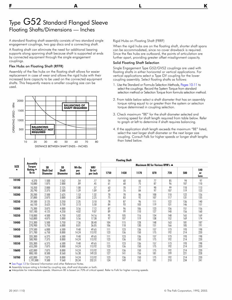
F A L K
A standard floating shaft assembly consists of two standard singleengagement couplings, two gap discs and a connecting shaft.
A floating shaft can eliminate the need for additional bearingsupports along spanning shaft because shaft is supported at endsby connected equipment through the single engagementcouplings.
Flex Hubs on Floating Shaft (RFFR)
Assembly of the flex hubs on the floating shaft allows for easierreplacement in case of wear and allows the rigid hubs with theirincreased bore capacity to be used on the connected equipmentshafts. This frequently means a smaller coupling size can beused.
Rigid Hubs on Floating Shaft (FRRF)
When the rigid hubs are on the floating shaft, shorter shaft spanscan be accommodated, since no cover drawback is required.Since the flex hubs are outboard, the points of articulation arefurther apart, providing greater offset misalignment capacity.
Solid Floating Shaft Selection
Single Engagement Type G52/GV52 couplings are used withfloating shafts in either horizontal or vertical applications. Forvertical applications select a Type GV coupling for the lowercoupling assembly. Select floating shafts as follows:
1. Use the Standard or Formula Selection Methods, Pages 10-11 toselect the couplings. Record the System Torque from standardselection method or Selection Torque from formula selection method.
2. From table below select a shaft diameter that has an assemblytorque rating equal to or greater than the system or selectiontorque determined in coupling selection.
3. Check maximum “BE” for the shaft diameter selected andrunning speed for shaft length required from table below. Referto graph at left to determine if shaft requires balancing.
4. If the application shaft length exceeds the maximum “BE” listed,select the next larger shaft diameter or the next larger sizecoupling. Consult Falk for higher speeds or longer shaft lengthsthan listed below.
2000
1500
1000
500
10 20 30 40 50 60 70 80
DISTANCE BETWEEN SHAFT ENDS – INCHES
OPERATIN
GSPEED
–RPM
BALANCINGNORMALLY NOTREQUIRED
BALANCING OFSHAFT REQUIRED
SIZE�
AssemblyTorque
Rating �lb-in
Floating Shaft
SBShaft EndDiameter
SDShaft
Diameter
Wt-lbsperinch
WR2
lb-in2
per inch
Maximum BE for Various RPM’s �
1750 1430 1170 870 720 580540or
Less
1010G 4,370 1.500 1.562 .54 .17 54 60 66 77 85 94 9710,080 1.875 2.000 .89 .45 61 68 75 87 96 107 110
1015G 10,350 2.000 2.125 1.00 .57 63 70 77 90 99 110 11320,790 2.375 2.500 1.39 1.09 69 76 84 97 107 119 123
1020G 20,200 2.500 2.625 1.53 1.32 70 78 86 100 110 122 12637,800 2.875 3.000 2.00 2.25 75 83 92 107 117 131 135
1025G 39,500 3.125 3.250 2.35 3.10 78 87 96 111 122 136 14066,150 3.625 3.750 3.13 5.50 84 93 103 119 131 146 151
1030G 75,300 3.875 4.000 3.56 7.12 87 96 106 123 136 151 156107,100 4.125 4.250 4.02 9.07 89 99 110 127 140 156 160
1035G 118,000 4.500 4.750 5.02 14.16 95 105 116 134 148 165 169163,800 4.875 5.000 5.56 17.38 97 107 119 138 152 169 174
1040G 215,300 5.500 5.750 7.36 30.40 104 115 128 148 163 181 187270,900 5.750 6.000 8.01 36.05 106 118 130 151 166 185 191
1045G 279,500 6.000 6.500 9.40 49.65 111 123 136 157 173 193 198371,700 6.750 8.000 14.24 113.92 123 136 150 175 192 214 220
1050G 335,300 6.375 6.500 9.40 49.65 111 123 136 157 173 193 198500,900 7.375 8.000 14.24 113.92 123 136 150 175 192 214 220
1055G 335,300 6.375 6.500 9.40 49.65 111 123 136 157 173 193 198655,200 7.875 8.000 14.24 113.92 123 136 150 175 192 214 220
1060G 632,000 7.875 8.000 14.24 113.92 123 136 150 175 192 214 220800,100 8.500 8.560 16.30 149.33 127 141 156 181 199 221 228
1070G 632,000 7.875 8.000 14.24 113.92 123 136 150 175 192 214 2201,197,000 9.500 9.560 20.34 232.31 134 149 165 191 210 234 241
� See Page 13 for General Information and other Reference Notes.
� Assembly torque rating is limited by coupling size, shaft end diameter or both.� Interpolate for intermediate speeds. Maximum BE is based on 70% of critical speed. Refer to Falk for higher running speeds.

© The Falk Corporation, 1992, 2003. (451-110) 21
Type G52 Standard Flanged SleeveFloating Shaft/Dimensions — Inches
GAP GAP
C FD
SD
SB
A
F LBEBETWEEN SHAFT ENDSL
FLEX HUB RIGID HUBFLEX HUB
GAP DISC GAP DISC
RIGID HUB
E
JQ LUBRICATETHRU SLEEVES
H H
GASKET
GASKET
GAP
SD
C
M
FLEX HUBRIGID HUB
MINIMUM CLEARANCEREQUIRED FOR ALIGNING
RIGID HUB
SBBETWEEN SHAFT ENDS
GAP DISC
A
F
FL
GAP
H H
D C
FLEX HUB
GAP DISC
E
QJ
LUBRICATETHRU SLEEVES
GASKET
GASKET
BE
Flex Hubs on Floating Shaft (RFFR)
For Sizes 1010G thru 1055G, TypeG51 Shrouded Bolts furnishedonly when specified on order.
Rigid Hubs on Floating Shaft (FRRF)
SIZE�
Max Bore �Min
Bore �
Wt–One CplgNo Bore–lb
LubeWtPerCplg
lb
A
BE Min
C D E F H J L M Q GapSIZE
�
FlexHub
RigidHub
G51 G52 RFFR FRRF
1010G 1.875 2.375 .50 9 10 .05 4.56 5.25 3.62 1.69 2.70 .10 3.30 .55 1.53 1.56 1.90 1.66 .156 1010G1015G 2.375 2.938 .75 18 20 .09 6.00 6.25 4.12 1.94 3.40 .10 4.14 .75 1.88 1.82 2.20 1.92 .156 1015G1020G 2.875 3.625 1.00 30 35 .15 7.00 7.75 5.06 2.44 4.14 .10 4.98 .75 2.34 2.30 2.70 2.40 .156 1020G1025G 3.625 4.375 1.25 55 60 .26 8.38 9.50 6.38 3.03 5.14 .10 6.10 .86 2.82 2.90 3.20 3.00 .188 1025G
1030G 4.125 5.125 1.50 85 95 .40 9.44 11.00 7.44 3.59 6.00 .10 7.10 .86 3.30 3.46 3.70 3.56 .188 1030G1035G 4.875 5.875 2.00 135 150 .60 11.00 12.75 8.62 4.19 7.00 .10 8.32 1.12 3.84 4.02 4.20 4.12 .218 1035G1040G 5.750 7.250 2.50 200 220 1.03 12.50 16.50 9.75 4.75 8.25 .16 9.66 1.12 4.38 4.54 4.80 4.70 .281 1040G1045G 6.750 8.125 3.00 285 300 1.25 13.62 20.00 11.06 5.31 9.25 .16 10.79 1.12 4.84 5.14 5.30 5.30 .312 1045G
1050G 7.375 9.000 3.50 400 430 2.00 15.31 21.00 12.44 6.03 10.00 .20 12.04 1.50 5.54 5.80 6.00 6.00 .344 1050G1055G 8.250 10.000 4.00 555 580 2.50 16.75 22.50 14.44 6.62 11.00 .20 13.16 1.50 6.22 6.80 6.80 7.00 .344 1055G1060G 9.125 11.000 4.50 . . . 715 3.75 18.00 23.50 15.62 7.41 12.00 .26 14.41 1.00 6.66 7.34 7.20 7.60 .406 1060G1070G 10.875 13.000 5.00 . . . 1120 5.00 20.75 26.50 18.50 8.69 14.00 .33 16.73 1.12 7.70 8.67 8.20 9.00 .500 1070G
� See Page 13 for General information and other Reference Notes.
See Previous Page for SB and SD Dimensions
22 (451-110) © The Falk Corporation, 1992, 2003.
F A L K
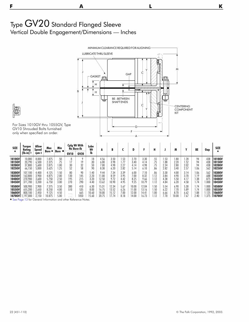
Type GV20 Standard Flanged SleeveVertical Double Engagement/Dimensions — Inches
Y M
C
Y
A
J
J
B H
H
GASKETGAP
BE - BETWEENSHAFT ENDS
F
D
C CENTERINGCOMPONENTKIT
MINIMUM CLEARANCE REQUIRED FOR ALIGNING
LUBRICATE THRU SLEEVE
SIZE�
TorqueRating
(lb-in) †
AllowSpeedrpm ‡
MaxBore �
MinBore �
Cplg Wt WithNo Bore-lb
LubeWtlb
A B C D F H J M Y BE GapSIZE
�
GV10 GV20
1010GV 10,080 8,000 1.875 .50 8 9 .18 4.56 3.50 1.53 2.70 3.30 .55 1.53 1.80 1.28 .94 .438 1010GV1015GV 20,790 6,500 2.375 .75 17 19 .30 6.00 3.98 1.77 3.40 4.14 .75 1.88 2.20 1.52 .94 .438 1015GV1020GV 37,800 5,600 2.875 1.00 30 32 .50 7.00 4.98 2.27 4.14 4.98 .75 2.34 2.80 2.02 .94 .438 1020GV1025GV 66,150 5,000 3.625 1.25 52 58 .90 8.38 6.20 2.82 5.14 6.10 .86 2.82 3.40 2.57 1.06 .562 1025GV
1030GV 107,100 4,400 4.125 1.50 80 90 1.40 9.44 7.34 3.39 6.00 7.10 .86 3.30 4.00 3.14 1.06 .562 1030GV1035GV 163,800 3,900 4.875 2.00 130 145 2.20 11.00 8.59 3.95 7.00 8.32 1.12 3.84 4.90 3.70 1.19 .688 1035GV1040GV 270,900 3,600 5.750 2.50 195 215 3.20 12.50 9.72 4.42 8.25 9.66 1.12 4.38 5.50 4.17 1.38 .875 1040GV1045GV 371,700 3,200 6.750 3.00 270 290 4.40 13.62 10.90 4.95 9.25 10.79 1.12 4.84 6.20 4.58 1.74 1.000 1045GV
1050GV 500,900 2,900 7.375 3.50 380 410 6.30 15.31 12.34 5.67 10.00 12.04 1.50 5.54 6.90 5.30 1.74 1.000 1050GV1055GV 655,200 2,650 8.250 4.00 510 535 8.00 16.75 13.52 6.26 11.00 13.16 1.50 6.22 7.70 5.89 1.74 1.000 1055GV1060GV 800,100 2,450 9.125 4.50 . . . 665 10.60 18.00 15.12 7.00 12.00 14.41 1.00 6.66 8.70 6.62 1.88 1.125 1060GV1070GV 1,197,000 2,150 10.875 5.00 . . . 1050 15.60 20.75 17.74 8.18 14.00 16.73 1.12 7.70 10.00 7.67 2.40 1.375 1070GV
� See Page 13 for General Information and other Reference Notes.
For Sizes 1010GV thru 1055GV, TypeGV10 Shrouded Bolts furnishedonly when specified on order.

© The Falk Corporation, 1992, 2003. (451-110) 23
SIZE�
TorqueRating
(lb-in) �†
AllowSpeedrpm �
MaxBore � Min
Bore �
Cplg Wt WithNo Bore-lb Lube
Wtlb
A B C D F H J L M R Y BE GapSIZE
�FlexHub
RigidHub
GV51 GV52
1010GV 10,080 7,000 1.875 2.375 .50 9 10 .08 4.56 3.42 1.53 2.70 3.30 .55 1.53 1.56 1.80 5.18 1.28 .580 .140 1010GV1015GV 20,790 5,500 2.375 2.938 .75 18 20 .12 6.00 3.92 1.77 3.40 4.14 .75 1.88 1.82 2.20 6.00 1.52 .580 .140 1015GV1020GV 37,800 4,600 2.875 3.625 1.00 32 35 .20 7.00 4.90 2.27 4.14 4.98 .75 2.34 2.30 2.80 7.20 2.02 .580 .140 1020GV1025GV 66,150 4,000 3.625 4.375 1.25 55 60 .40 8.38 6.11 2.82 5.14 6.10 .86 2.82 2.90 3.40 8.57 2.57 .640 .200 1025GV
1030GV 107,100 3,600 4.125 5.125 1.50 85 95 .60 9.44 7.24 3.39 6.00 7.10 .86 3.30 3.46 4.00 9.75 3.14 .640 .200 1030GV1035GV 163,800 3,100 4.875 5.875 2.00 135 150 1.00 11.00 8.43 3.95 7.00 8.32 1.12 3.84 4.02 4.90 11.73 3.70 .710 .260 1035GV1040GV 270,900 2,800 5.750 7.250 2.50 205 225 1.50 12.50 9.58 4.42 8.25 9.66 1.12 4.38 4.54 5.50 13.40 4.17 .865 .300 1040GV1045GV 371,700 2,600 6.750 8.125 3.00 285 305 2.00 13.62 10.77 4.95 9.25 10.79 1.12 4.84 5.14 6.20 15.28 4.58 1.050 .360 1045GV
1050GV 500,900 2,400 7.375 9.000 3.50 405 435 3.00 15.31 12.19 5.67 10.00 12.04 1.50 5.54 5.80 6.90 16.68 5.30 1.090 .315 1050GV1055GV 655,200 2,200 8.250 10.000 4.00 560 585 3.70 16.75 13.78 6.26 11.00 13.16 1.50 6.22 6.80 7.70 18.28 5.89 1.090 .315 1055GV1060GV 800,100 2,100 9.125 11.000 4.50 . . . 860 5.00 18.00 15.18 7.00 12.00 14.41 1.00 6.66 7.34 8.70 20.56 6.62 1.215 .315 1060GV1070GV 1,197,000 1,800 10.875 13.000 5.00 . . . 1140 7.20 20.75 17.88 8.18 14.00 16.73 1.12 7.70 8.67 10.00 24.22 7.67 1.540 .380 1070GV
� See Page 13 for General Information and other Reference Notes.� Torque Rating is for coupling only, refer to Page 20 for floating shaft selection and ratings.� Allowable speed listed is for GV52 coupling only, refer to Page 20 for floating shaft selection and running speed.
Y M
C
L
J
B
H
H
GASKET
GAP
BE - BETWEENSHAFT ENDS
A
F
D
CENTERINGCOMPONENTKIT
MINIMUM CLEARANCE REQUIRED FOR ALIGNING
LUBRICATETHRU SLEEVE
FLEX HUB
RIGID HUB
Type GV52 Standard Flanged SleeveVertical Single Engagement/Dimensions — Inches
For Sizes 1010GV thru 1055GV, TypeGV51 Shrouded Bolts furnishedonly when specified on order.
RMinimumDistanceBetweenShafts
Use G52at Top
Use GV52at Bottom
FloatingShaftDesign

24 (451-110) © The Falk Corporation, 1992, 2003.
F A L K
Types G62, G63 & G66 Standard Flanged SleeveBrakewheel/Disc Brake/Dimensions — Inches
Straight Bores — Wheel Sizes 7" Diameter & Larger
MD
AB
JB
NC
M
A
J
B
FD
C C
W
HH
GAP
MC
NB
LUBRICATETHRU SLEEVE
BRAKE CL
MD
AB
JB
NC
A
QJ
B
FFD
C L
W
HH
GAP
MC
NB
BRAKE CL
MINIMUM CLEARANCE REQUIRED FOR ALIGNING
RIGID HUB
FLEX HUB
E
AC
M
A
J
B
FD
C C
W
HH
GAP
MC
NB
LUBRICATETHRU SLEEVE
DISC CL
MINIMUM CLEARANCE REQUIRED FOR ALIGNING
JC
Double Engagement Type G62 Single Engagement Type G66 Double Engagement Type G63�
Brake-wheelSize � CPLG
SIZE�
BrakeRating
ofCoup-ling
(ft-lb)
Max StraightBore � Min
Bore�
Coupling WtNo Bore-lbLess Wheel
LubeWt-lb
A
B
C D E F H J L M Q W
Gap
Dia(Min)
AB
FlexHub
RigidHub
G62G63
G66G62G63
G66G62G63
G66WithStd
LengthHubs
G62G63
G66
7 1010G 185 1.875 2.375 .50 10 10 .10 .06 4.56 3.88 3.79 1.69 2.70 .10 3.30 .55 1.53 1.56 2.00 1.66 .38 .500 .5368 1015G 420 2.375 2.938 .75 20 20 .20 .12 6.00 4.50 4.42 1.94 3.40 .10 4.14 .75 1.88 1.82 2.40 1.92 .50 .625 .6569.62 1020G 775 2.875 3.625 1.00 35 35 .30 .20 7.00 5.50 5.40 2.44 4.14 .10 4.98 .75 2.34 2.30 3.00 2.40 .50 .625 .656
11.38 1025G 1400 3.625 4.375 1.25 65 60 .60 .35 8.38 6.81 6.68 3.03 5.14 .10 6.10 .86 2.82 2.90 3.60 3.00 .56 .750 .748
12.62 1030G 2300 4.125 5.125 1.50 95 95 .90 .50 9.44 7.93 7.80 3.59 6.00 .10 7.10 .86 3.30 3.46 4.20 3.56 .56 .750 .74814.62 1035G 3550 4.875 5.875 2.00 150 150 1.25 .75 11.00 9.38 9.18 4.19 7.00 .10 8.32 1.12 3.84 4.02 5.10 4.12 .75 1.000 .96816.88 1040G 5400 5.750 7.250 2.50 215 220 2.00 1.20 12.50 10.50 10.31 4.75 8.25 .16 9.66 1.12 4.38 4.54 5.70 4.70 .75 1.000 1.03118 1045G 7400 6.750 8.125 3.00 300 300 2.50 1.40 13.62 11.68 11.50 5.31 9.25 .16 10.79 1.12 4.84 5.14 6.50 5.30 .75 1.062 1.062
19.38 1050G 10000 7.375 9.000 3.50 420 430 4.12 2.50 15.31 13.37 13.17 6.03 10.00 .20 12.04 1.50 5.54 5.80 7.20 6.00 1.00 1.312 1.34420.88 1055G 13125 8.250 10.000 4.00 550 580 5.12 3.00 16.75 14.56 14.76 6.62 11.00 .20 13.16 1.50 6.22 6.80 8.00 7.00 1.00 1.312 1.34423 1060G 17000 9.125 11.000 4.50 675 715 7.50 4.25 18.00 16.12 16.16 7.41 12.00 .26 14.41 1.00 6.66 7.34 9.00 7.60 1.00 1.312 1.40626 1070G 24700 10.875 13.000 5.00 1070 1120 9.80 5.75 20.75 18.75 18.86 8.69 14.00 .33 16.73 1.12 7.70 8.67 10.50 9.00 1.00 1.375 1.500
� See Page 13 for General Information and other Reference Notes.� Maximum rim velocity is 6000 feet per minute. Brakewheel must be balanced if peripheral speed exceeds 6000 feet per minute.� Dimensions and allowable speed vary with application; consult Falk.� Dimensions AC and JC depend upon customer caliper specifications.

© The Falk Corporation, 1992, 2003. (451-110) 25
Types G62/G66 Standard Flanged SleeveBrakewheel (for AISE Brakes)/Dimensions — Inches
Taper Bores — Wheel Sizes 8" – 30" Diameter & Larger
BRAKE BASELINE
CLFLEXHUB FLEX HUB
AB
ZE
MOTOR END
JB
MA
MB
ZD
NB
NC
C
M
GAP
MA
X.
BO
RE
MINIMUM CLEARANCE REQUIREDFOR ALIGNING.
BRAKE BASELINE
CL
RIGIDHUB FLEX HUB
AB
ZE
MOTOR END
JB
MA
MB
ZD
NB
NC
L
MINIMUM CLEARANCE REQUIRED
GAP
MA
X.
BO
RE
FOR ALIGNING.
BRAKEBASELINE
CLFLEXHUB RIGID HUB
AB
ZE
MOTOR END
JB
MC
MD
ZD
NB
NC
C
MINIMUM CLEARANCE REQUIRED
GAP
MA
X.
BO
RE
FOR ALIGNING.
Double Engagement Type G62(One Hub Taper Bored)
Figure 1
Single Engagement Type G66(Flex Hub Taper Bored)
Figure 2
Single Engagement Type G66(Rigid Hub Taper and C’ Bored)
Figure 3
BrakewheelDia. x Face
�Wheel
DrawingNumber
CPLGSIZE
�
MillMotorSize
AllowSpeedrpm�
BrakeRatinglb-ft
Brake Manufacturer& Catalog Number
C L MMAMBMax
MCMDMax
NB
NC ZD ZE
Gap
DimensionsAB x JB
C-HCo.
E.C. &M.
G.E. WestFig
1 & 3Fig2
Fig1
Fig2 & 3
8 x 3.25 330155 1015G 802 2,860 100 8 T-08 A100 TM83 1.94 1.82 2.40 4.50 2.90 .56 .61 1.47 .94 3.00 .625 .66010 x 3.75 330156 1015G 803,804 2,290 200 10 T-10 A101 TM1035 1.94 1.82 2.40 5.00 2.90 .88 .92 2.03 1.00 3.50 .625 .66013 x 5.75 330158 1020G 806 1,760 550 13 T-13 A102 TM1355 2.44 2.30 3.00 5.62 3.50 .75 .80 2.91 1.13 4.00 .625 .66013 x 5.75 330159 1025G 808 1,760 550 13 T-13 A102 TM1355 3.03 2.90 3.60 6.25 4.10 1.12 1.14 3.19 1.25 4.50 .750 .750
16 x 6.75 330160 1025G 810 1,430 1000 16 T-16 A103 TM1665 3.03 2.90 3.60 6.38 4.72 .12 � .14 2.69 1.38 4.50 .750 .75019 x 8.75 330162 1030G 812 1,200 2000 19 T-19 A104 TM1985 3.59 3.46 4.20 7.00 5.88 .25 � .23 3.31 1.50 5.00 .750 .75019 x 8.75 330163 1035G 814 1,200 2000 19 T-19 A104 TM1985 4.19 4.02 5.10 7.12 6.58 .12 .12 3.47 1.63 5.00 1.000 .98023 x 11.25 330164 1040G 816 995 4000 23 T-23 A105 TM2311 4.75 4.54 5.70 8.20 7.82 0 .05 4.59 1.75 5.50 1.000 1.050
23 x 11.25 330165 1040G 818 995 4000 23 T-23 A105 TM2311 4.75 4.54 5.70 8.31 8.26 .44 � .39 � 4.16 1.31 6.00 1.000 1.05030 x 14.25 330166 1050G 820 765 9000 30 . . . . . . . 6.03 5.80 7.20 8.50 10.63 .44 � .37 � 5.38 1.75 6.75 1.312 1.36030 x 14.25 330167 1050G 822 765 9000 30 . . . . . . . 6.03 5.80 7.20 9.62 9.76 .19 .25 6.00 2.37 7.25 1.312 1.360
� See Page 13 for General Information and other Reference Notes.� For standard AISE and 600 series brakes, refer to Table 6, Page 34.� Based on maximum rim velocity of 6000 feet per minute.� Symbol indicates that Dimension NB and the brakewheel centerline are to the left of the hub face.

26 (451-110) © The Falk Corporation, 1992, 2003.
F A L K
SIZE�
Type GL20-1 Type GL20-2 Type GL20-4 �
BMax
MT (Max) Gap B
MaxM
T (Max) Gap BMax
MT (Max) Gap
Each Total Min Max Each Total Min Max Each Total Min Max
1010GL 3.79 2.12 . 05 .10 .31 .41 4.97 2.30 .64 1.28 .31 1.59 3.79 2.12 .08 .17 .24 .411015GL 5.01 2.35 .41 .82 .31 1.13 6.01 2.70 .91 1.82 .31 2.13 5.01 2.35 .29 .59 .54 1.131020GL 5.93 3.04 .37 .74 .31 1.05 7.33 3.30 1.07 2.14 .31 2.45 5.93 3.04 .39 .79 .26 1.051025GL 7.39 3.68 .48 .96 .37 1.33 9.11 4.00 1.34 2.68 .37 3.05 7.39 3.68 .24 .49 .84 1.33
1030GL 8.95 4.26 .70 1.40 .37 1.77 10.37 3.60 1.41 2.82 .37 3.19 8.95 4.26 .45 .91 .86 1.771035GL 10.77 4.90 .97 1.94 .45 2.39 12.39 4.10 1.78 3.56 .45 4.01 10.77 4.90 .55 1.10 1.29 2.391040GL 12.61 5.46 1.27 2.54 .57 3.11 14.27 4.70 2.10 4.20 .57 4.77 12.61 5.46 .64 1.28 1.83 3.111045GL 13.99 6.08 1.37 2.74 .63 3.37 15.97 5.10 2.36 4.72 .63 5.35 13.99 6.08 .76 1.52 1.85 3.37
1050GL 16.07 6.91 1.65 3.30 .71 4.01 18.09 5.90 2.66 5.32 .71 6.03 16.07 6.91 .81 1.63 2.38 4.011055GL 18.51 7.51 2.28 4.56 .71 5.27 20.09 6.60 3.07 6.14 .71 6.85 18.51 7.51 .83 1.66 3.61 5.271060GL 19.83 8.33 2.09 4.18 .83 5.01 22.17 7.20 3.26 6.52 .83 7.35 19.83 8.33 .97 1.95 3.06 5.011070GL 23.30 9.66 2.44 4.88 1.04 5.92 26.16 8.30 3.87 7.74 1.04 8.78 23.30 9.66 1.06 2.13 3.79 5.92
� See Page 13 for General Information and other Reference Notes.� Gap discs are not required for Sizes 1010 and 1020GL.
SIZE�
TorqueRating
(lb-in) †
AllowSpeedrpm ‡
MaxBore �
MinBore �
Cplg Wtwith
No Bore-lb
LubeWtlb
A C D F H JSIZE
�
1010GL 10,080 5,300 1.875 .50 10 .05 4.56 1.69 2.70 3.30 .55 1.53 1010GL1015GL 20,790 4,300 2.375 .75 20 .08 6.00 1.94 3.40 4.14 .75 1.88 1015GL1020GL 37,800 3,700 2.875 1.00 35 .14 7.00 2.44 4.14 4.98 .75 2.34 1020GL1025GL 66,150 3,300 3.625 1.25 65 .25 8.38 3.03 5.14 6.10 .86 2.82 1025GL
1030GL 107,100 2,900 4.125 1.50 90 .40 9.44 3.59 6.00 7.10 .86 3.30 1030GL1035GL 163,800 2,600 4.875 2.00 150 .60 11.00 4.19 7.00 8.32 1.12 3.84 1035GL1040GL 270,900 2,400 5.750 2.50 220 1.00 12.50 4.75 8.25 9.66 1.12 4.38 1040GL1045GL 371,700 2,100 6.750 3.00 300 1.12 13.62 5.31 9.25 10.79 1.12 4.84 1045GL
1050GL 500,900 1,900 7.375 3.50 425 2.00 15.31 6.03 10.00 12.04 1.50 5.54 1050GL1055GL 655,200 1,800 8.250 4.00 560 2.50 16.75 6.62 11.00 13.16 1.50 6.22 1055GL1060GL 800,100 1,600 9.125 4.50 700 3.50 18.00 7.41 12.00 14.41 1.00 6.66 1060GL1070GL 1,197,000 1,400 10.875 5.00 1100 4.80 20.75 8.69 14.00 16.73 1.12 7.70 1070GL
Type GL20 Standard Flanged SleeveSlide Double Engagement/Dimensions — Inches
GASKETB
J J
H
AGAP F
D
H
TCC
M M
T
CENTERPLATE
FLEXHUB
FLEXHUB
LUBRICATETHRUSLEEVE
GLSLEEVE
MINIMUM CLEARANCE REQUIRED FOR ALIGNING
GASKETB
J J
H
AGAP F
D
H
TCC
M M
T
CENTERPLATE
FLEXHUB
FLEXHUB
LUBRICATETHRUSLEEVE
GLSLEEVE
MINIMUM CLEARANCE REQUIRED FOR ALIGNING
GASKETB
J J
H
AGAP F
D
H
TCC
M M
T
CENTERPLATE
FLEXHUB
FLEX HUB
LUBRICATETHRUSLEEVE
GAP DISC(BOTH SIDES)
MINIMUM CLEARANCE REQUIRED FOR ALIGNING
Type GL20-1Long Tooth SleeveReversed Std. Hubs
Center Plate
Type GL20-2Long Tooth SleevesCutoff Long Hubs
Center Plate
Type GL20-4Std. Tooth SleevesReversed Std. Hubs
Center Plate
Choosing an Assembly
Select the assembly that provides a Total “T” dimension from the table below equal to the application requirements.
GL20-1 Moderate slide capacity, moderate price.GL20-2 Greatest slide capacity, highest price.GL20-4 Least slide capacity, lowest price.

© The Falk Corporation, 1992, 2003. (451-110) 27
Type GL52 Standard Flanged SleeveSlide Single Engagement/Dimensions — Inches
H
B
M
FD
A
F
GAP
QJ
H
GASKET
TC
MINIMUM CLEARANCE REQUIREDFOR ALIGNING
FLEXHUB RIGID
HUBLUBRICATETHRUSLEEVE
GL SLEEVE
B
E
L
MIN.
MAX.
H
M
F
GL SLEEVE
D
A
F
L
GAP
QJ
BGASKET
TC
E
MINIMUM CLEARANCE REQUIREDFOR ALIGNING
FLEXHUB RIGID
HUBLUBRICATETHRUSLEEVE
H
MIN.
MAX.
Type GL52-1 Long Tooth SleeveReversed Std. Hub
Type GL52-2 Long Tooth SleeveCutoff Long Hub
Choosing an Assembly
Select the assembly that provides a Total “T” dimension from the table below equal to the application requirements.
GL52-1 — Moderate slide capacity, moderate price.GL52-2 — Greatest slide capacity, highest price.
SIZE�
Type GL52-1 Type GL52-2
BMax
MT
Max
Gap BMax
MT
Max
Gap
Min Max Min Max
1010GL 3.55 2.12 .14 .16 .30 4.14 2.30 .73 .16 .891015GL 4.42 2.35 .50 .16 .66 4.92 2.70 1.00 .16 1.161020GL 5.36 3.34 .46 .16 .62 6.06 3.30 1.16 .16 1.321025GL 6.68 3.68 .57 .19 .76 7.55 4.00 1.43 .19 1.62
1030GL 8.03 4.26 .79 .19 .98 8.74 3.60 1.50 .19 1.691035GL 9.50 4.90 1.07 .22 1.29 10.31 4.10 1.88 .22 2.101040GL 11.00 5.46 1.43 .28 1.71 11.83 4.70 2.26 .28 2.541045GL 12.39 6.08 1.53 .31 1.84 13.30 5.10 2.52 .31 2.83
1050GL 14.02 6.91 1.85 .34 2.19 15.03 5.90 2.86 .34 3.201055GL 16.24 7.51 2.48 .34 2.82 17.03 6.60 3.27 .34 3.611060GL 17.51 8.33 2.35 .41 2.76 18.68 7.20 3.52 .41 3.931070GL 20.63 9.66 2.77 .50 3.27 22.06 8.30 4.20 .50 4.70
SIZE�
TorqueRating
(lb-in) †
AllowSpeedrpm ‡
Max Bore �Min
Bore �
Cplg WtwithNo
Bore-lb
LubeWtlb
A C D E F H J L QSIZE
�FlexHub
RigidHub
1010GL 10,080 5,300 1.875 2.375 .50 10 .30 4.56 1.69 2.70 .10 3.30 .55 1.53 1.56 1.66 1010GL1015GL 20,790 4,300 2.375 2.938 .75 20 .05 6.00 1.94 3.40 .10 4.14 .75 1.88 1.82 1.92 1015GL1020GL 37,800 3,700 2.875 3.625 1.00 35 .08 7.00 2.44 4.14 .10 4.98 .75 2.34 2.30 2.40 1020GL1025GL 66,150 3,300 3.625 4.375 1.25 65 .14 8.38 3.03 5.14 .10 6.10 .86 2.82 2.90 3.00 1025GL
1030GL 107,100 2,900 4.125 5.125 1.50 95 .25 9.44 3.59 6.00 .10 7.10 .86 3.30 3.46 3.56 1030GL1035GL 163,800 2,600 4.875 5.875 2.00 150 .40 11.00 4.19 7.00 .10 8.32 1.12 3.84 4.02 4.12 1035GL1040GL 270,900 2,400 5.750 7.250 2.50 220 .60 12.50 4.75 8.25 .16 9.66 1.12 4.38 4.54 4.70 1040GL1045GL 371,700 2,100 6.750 8.125 3.00 300 .75 13.62 5.31 9.25 .16 10.79 1.12 4.84 5.14 5.30 1045GL
1050GL 500,900 1,900 7.375 9.000 3.50 430 1.20 15.31 6.03 10.00 .20 12.04 1.50 5.54 5.80 6.00 1050GL1055GL 655,200 1,800 8.250 10.000 4.00 580 1.60 16.75 6.62 11.00 .20 13.16 1.50 6.22 6.80 7.00 1055GL1060GL 800,100 1,600 9.125 11.000 4.50 715 2.12 18.00 7.41 12.00 .26 14.41 1.00 6.66 7.34 7.60 1060GL1070GL 1,197,000 1,400 10.875 13.000 5.00 1125 3.00 20.75 8.69 14.00 .33 16.73 1.12 7.70 8.67 9.00 1070GL
� See Page 13 for General Information and Reference Notes.

28 (451-110) © The Falk Corporation, 1992, 2003.
F A L K
Type G70Disconnect (Inching Drives)/Dimensions — Inches
M
T
P C
D
AE
B
AB
AA
ACZG
GAP
LUBRICATE GEAR TEETH ANDSLEEVE PIN GROOVE WITHMOLYKOTE BR-2 PLUSOR EQUIVALENT.
MINIMUM CLEARANCE REQUIREDFOR ALIGNING
V
DrivenEnd
DrivingEnd
Optional hand operated shifter mechanism to shift andsecure the proper position of the sleeve assembly.
SIZE�
TorqueRating
(lb-in) †
AllowSpeedrpm ‡
MaxBore �
MinBore �
Cplg WtWith NoBore-lb
B C D M P T V AA AB AC AE ZG GapSIZE
�
1010G 10,080 630 1.875 .50 9 4.56 1.69 2.70 2.74 2.74 1.18 .86 3.82 3.30 .32 2.36 .58 .125 1010G1015G 20,790 500 2.375 .75 15 4.76 1.94 3.40 2.70 2.70 1.16 .84 4.76 4.23 .32 2.32 .50 .125 1015G1020G 37,800 400 2.875 1.00 30 6.02 2.44 4.14 3.46 3.46 1.50 1.14 5.74 5.10 .44 3.08 .70 .125 1020G1025G 66,150 330 3.625 1.25 53 7.42 3.03 5.14 4.20 4.20 1.90 1.48 6.80 6.16 .44 3.82 .86 .188 1025G
1030G 107,100 280 4.125 1.50 80 8.50 3.59 6.00 4.72 4.72 2.16 1.68 7.92 7.16 .56 4.34 .96 .188 1030G1035G 163,800 240 4.875 2.00 123 9.70 4.19 7.00 5.26 5.26 2.48 1.90 9.10 8.35 .56 4.88 1.06 .250 1035G1040G 270,900 200 5.750 2.50 183 10.62 4.75 8.25 5.62 5.62 2.66 2.08 10.60 9.85 .56 5.24 1.08 .250 1040G1045G 371,700 180 6.750 3.00 262 12.04 5.31 9.25 6.42 6.42 3.04 2.36 11.74 10.85 .68 6.04 1.24 .312 1045G
1050G 500,900 170 7.375 3.50 353 13.34 6.03 10.00 7.00 7.00 3.32 2.64 13.04 12.16 .68 6.60 1.37 .312 1050G1055G 655,200 150 8.250 4.00 439 14.04 6.62 11.00 7.10 7.10 3.38 2.68 14.04 13.16 .68 6.70 1.29 .312 1055G1060G 800,100 140 9.125 4.50 603 16.02 7.41 12.00 8.30 8.30 3.94 3.22 15.62 14.41 .76 7.92 1.67 .312 1060G1070G 1,197,000 120 10.875 5.00 935 18.36 8.69 14.00 9.40 9.30 4.60 3.67 17.94 16.73 .76 9.03 1.96 .375 1070G
� See Page 13 for General Information and other Reference Notes.

© The Falk Corporation, 1992, 2003. (451-110) 29
Type G72Disconnect/Dimensions — Inches
MC
N
F
A
AC
LUBRICATE SLIDING SURFACES WITHMOLYKOTE BR-2 PLUS OR EQUIVALENT
T
P
D
B
LONG HUB
FREE RUNNING HUB
MINIMUM CLEARANCE REQUIREDFOR ALIGNING
AB
AD
AA GAP
2 PINS LOCATED180 APART
LUBRICATE THRU SLEEVE
Optional hand operated shifter mechanism to shift andsecure the proper position of the sleeve assembly.
SIZE�
TorqueRating
(lb-in) †
AllowSpeedrpm ‡
Max Bore �Min
Bore �
Cplg WtWith NoBore-lb
LubeWtlb
A B C D F M N P T AA AB AC AD GapSIZE
�LongHub
FreeHub
1010G 10,080 4,200 1.875 1.500 .50 15 .07 4.56 5.06 1.68 2.70 3.30 2.30 2.25 3.25 .50 6.25 5.00 .62 3.68 .125 1010G1015G 20,790 3,200 2.375 2.062 .75 29 .12 6.00 5.81 2.06 3.40 4.14 3.00 3.00 3.62 .56 7.25 6.00 .62 4.26 .125 1015G1020G 37,800 2,450 2.875 2.688 1.00 50 .20 7.00 7.06 2.44 4.14 4.98 3.30 3.88 4.50 .88 7.75 6.50 .62 5.38 .125 1020G1025G 66,150 2,000 3.625 3.250 1.25 79 .38 8.38 8.44 2.88 5.14 6.10 3.60 4.75 5.38 .88 9.00 7.50 .75 6.50 .188 1025G
1030G 107,100 1,650 4.125 4.000 1.50 115 .60 9.44 9.68 3.88 6.00 7.10 4.20 5.75 5.62 1.00 9.75 8.50 .88 7.86 .188 1030G1035G 163,800 1,530 4.875 4.312 2.00 180 .90 11.00 10.88 4.00 7.00 8.32 4.10 6.25 6.62 1.12 11.88 10.62 .88 8.64 .250 1035G1040G 270,900 1,200 5.750 5.562 2.50 267 1.50 12.50 12.05 4.42 8.25 9.66 4.90 8.00 7.38 1.25 13.88 11.62 1.00 9.66 .250 1040G1045G 371,700 1,060 6.750 6.188 3.00 336 1.70 13.62 12.38 4.82 9.25 10.79 5.50 8.88 7.25 1.56 15.50 13.00 1.00 9.91 .312 1045G
1050G 500,900 950 7.375 7.375 3.50 461 3.00 15.31 14.19 5.62 10.00 12.04 7.20 10.00 8.25 1.75 15.00 12.75 1.00 11.16 .312 1050G1055G 655,200 860 8.250 7.375 4.00 612 3.70 16.75 15.19 6.62 11.00 13.16 7.25 10.00 8.25 2.12 17.75 15.75 1.12 13.31 .312 1055G1060G 800,100 830 9.125 8.625 4.50 809 5.25 18.00 18.31 7.12 12.00 14.41 7.62 11.50 10.88 2.00 18.25 16.62 1.12 14.56 .312 1060G1070G 1,197,000 680 10.875 10.875 5.00 1155 7.20 20.75 18.88 7.75 14.00 16.73 10.50 14.00 10.75 2.25 23.00 20.00 1.12 15.08 .375 1070G
� See Page 13 for General Information and Reference Notes.

30 (451-110) © The Falk Corporation, 1992, 2003.
F A L K
Type GP20/52/82 Standard Flanged SleeveInsulated/Dimensions — Inches
C
M M
C
JJ
.125
GAP
B
H H
DF
A
LUBRICATETHRU SLEEVE
LUBRICATETHRU SLEEVE
MINIMUM CLEARANCE REQUIRED FOR ALIGNING
D
C
M
L
QJ
.125
E
GAP
B
H H
FFA
LUBRICATETHRU SLEEVE
MINIMUM CLEARANCE REQUIRED FOR ALIGNING
RIGID HUBFLEX HUB
Type GP20 Double Engagement Coupling Type GP52 Single Engagement Coupling
SIZE�
TorqueRating
(lb-in) †
AllowSpeedrpm ‡
Max Bore � MinBore�
Cplg Wt WithNo Bore-lb
LubeWt-lb
FlexHub
RigidHub
GP20 GP52 GP82 GP20 GP52
1025G 66,150 5,000 3.625 4.375 1.25 65 60 60 .50 .261030G 107,100 4,400 4.125 5.125 1.50 95 95 95 .80 .401035G 163,800 3,900 4.875 5.875 2.00 150 150 155 1.20 .60
1040G 270,900 3,600 5.750 7.250 2.50 215 220 225 2.00 1.031045G 371,700 3,200 6.750 8.125 3.00 300 300 310 2.30 1.251050G 500,900 2,900 7.375 9.000 3.50 420 430 450 3.90 2.00
1055G 655,200 2,650 8.250 10.000 4.00 550 580 620 4.90 2.501060G 800,100 2,450 9.125 11.000 4.50 675 715 740 7.00 3.751070G 1,197,000 2,150 10.875 13.000 5.00 1070 1120 1180 9.60 5.00
� See Page 13 for General Information and other Reference Notes.
L
.125
E
GAP
B
H H
FA
L
Type GP82 Rigid Coupling
INSULATORBUSHINGS
INSULATORWASHERS
INSULATORCENTER PLATE
SIZE�
Flange Bolt
A
B
C D E F H J L M Q
GapSIZE
�Dia & LengthTorque(lb-in)
GP20 GP52 GP82 GP20 GP52 GP82
1025GP .500-13 x 3.00 420 8.38 6.38 6.24 6.12 3.03 5.14 .10 6.10 .86 2.82 2.90 3.60 3.00 .325 .325 .335 1025GP1030GP .500-13 x 3.00 420 9.44 7.49 7.36 7.24 3.59 6.00 .10 7.10 .86 3.30 3.46 4.20 3.56 .325 .325 .335 1030GP1035GF .625-11 x 4.00 840 11.00 8.75 8.55 8.36 4.19 7.00 .10 8.32 1.12 3.84 4.02 5.10 4.12 .385 .350 .335 1035GF
1040GP .625-11 x 4.00 840 12.50 9.88 9.68 9.52 4.75 8.25 .16 9.66 1.12 4.38 4.54 5.70 4.70 .385 .420 .455 1040GP1045GP .625-11 x 4.00 840 13.62 11.06 10.87 10.72 5.31 9.25 .16 10.79 1.12 4.84 5.14 6.50 5.30 .450 .450 .455 1045GP1050GP .750-10 x 5.00 1440 15.31 12.49 12.29 12.12 6.03 10.00 .20 12.04 1.50 5.54 5.80 7.20 6.00 .450 .480 .535 1050GP
1055GP .750-10 x 5.00 1440 16.75 13.68 13.88 14.12 6.62 11.00 .20 13.16 1.50 6.22 6.80 8.00 7.00 .450 .480 .535 1055GP1060GP .750-10 x 4.00 1440 18.00 15.24 15.28 15.32 7.41 12.00 .26 14.41 1.00 6.66 7.34 9.00 7.60 .450 .540 .655 1060GP1070GP .875- 9 x 4.50 1800 20.75 17.89 17.98 18.12 8.69 14.00 .33 16.73 1.12 7.70 8.67 10.50 9.00 .510 .635 .795 1070GP

© The Falk Corporation, 1992, 2003. (451-110) 31
Type G82 Standard Flanged SleeveRigid/Dimensions — Inches
L L
F
A
H
Q Q
B
GAP
E
H Type G81 Shrouded Bolts furnishedonly when specified on order. Sizes1060G and 1070G available onlyas Type G82.
SIZE�
TorqueRating
(lb-in) †
AllowSpeedrpm ‡
MaxBore �
MinBore �
Cplg Wt WithNo Bore-lb A B E F H L Q Gap
SIZE�
G81 G82
1010G 10,080 8,000 2.375 .50 9 10 4.56 3.32 .10 3.30 .55 1.56 1.66 .200 1010G1015G 20,790 6,500 2.938 .75 19 20 6.00 3.84 .10 4.14 .75 1.82 1.92 .200 1015G1020G 37,800 5,600 3.625 1.00 30 35 7.00 4.80 .10 4.98 .75 2.30 2.40 .200 1020G1025G 66,150 5,000 4.375 1.25 55 60 8.38 6.00 .10 6.10 .86 2.90 3.00 .200 1025G
1030G 107,100 4,400 5.125 1.50 90 95 9.44 7.12 .10 7.10 .86 3.46 3.56 .200 1030G1035G 163,800 3,900 5.875 2.00 135 155 11.00 8.24 .10 8.32 1.12 4.02 4.12 .200 1035G1040G 270,900 3,600 7.250 2.50 210 225 12.50 9.40 .16 9.66 1.12 4.54 4.70 .320 1040G1045G 371,700 3,200 8.125 3.00 290 310 13.62 10.60 .16 10.79 1.12 5.14 5.30 .320 1045G
1050G 500,900 2,900 9.000 3.50 415 450 15.31 12.00 .20 12.04 1.50 5.80 6.00 .400 1050G1055G 655,200 2,650 10.000 4.00 590 620 16.75 14.00 .20 13.16 1.50 6.80 7.00 .400 1055G1060G 800,100 2,450 11.000 4.50 . . . 740 18.00 15.20 .26 14.41 1.00 7.34 7.60 .520 1060G1070G 1,197,000 2,150 13.000 5.00 . . . 1180 20.75 18.00 .33 16.73 1.12 8.67 9.00 .660 1070G
� See Page 13 for General Information and other Reference Notes.

32 (451-110) © The Falk Corporation, 1992, 2003.
F A L K
Type GV82 Standard Flanged SleeveRigid Thrust/Dimensions — Inches
RIGID COUPLING
MIXER SHAFT
Q
GA
PL
F
KEYWAY
A
L
U
U
Q
BH
HE
X-
W
DIAMETER PILOT HOLE THRU ONEWALL IN EACH HUB AT 90 TO KEYWAYFOR -DOWEL. AFTER MOUNTINGHUBS, DRILL AND REAM THRU FOR .0010"TTO .0005"L DOWEL FIT. STAKE DOWELSIN PLACE.
DOWEL PINS
Type GV82 couplings are used as rigid connections for the lowspeed shaft of a gear drive and a mixer shaft or suspended load.The coupling carries the torque load, weight of the shaft andimpeller, thrust forces and resulting bending moments.
When a rigid coupling is required, the following additionalinformation is necessary.
1. Required thrust capacity and direction of thrust.
2. Radial force at impeller.
3. Distance from the center of coupling fastener flange to thecenter of the impeller.
4. Weight of shaft and impeller.
SIZE�
TorqueRating
(lb-in) †
Hub BoreRange �
CplgWt With
NoBore-lb
A B E F H L Q U
W �
X GapSize�Dowel
Dia x Length
DowelHole-Dia+.0005
–-.0000
1010GV 10,080 1.375- 2.250 10 4.56 3.32 .10 3.30 .55 1.56 1.66 .38 .375 x 3.22 .3740 .344 .200 1010GV1015GV 20,790 1.625- 2.750 20 6.00 3.84 .10 4.14 .75 1.82 1.92 .50 .500 x 4.06 .4990 .469 .200 1015GV1020GV 37,800 2.500- 3.250 35 7.00 4.80 .10 4.98 .75 2.30 2.40 .75 .750 x 4.88 .7490 .719 .200 1020GV1025GV 66,150 3.250- 4.000 60 8.38 6.00 .10 6.10 .86 2.90 3.00 1.00 1.000 x 5.98 .9990 .938 .200 1025GV
1030GV 107,100 3.500- 4.500 95 9.44 7.12 .10 7.10 .86 3.46 3.56 1.12 1.125 x 6.96 1.1240 1.063 .200 1030GV1035GV 163,800 4.000- 5.250 155 11.00 8.24 .10 8.32 1.12 4.02 4.12 1.25 1.250 x 8.20 1.2490 1.188 .200 1035GV1040GV 270,900 4.500- 6.250 225 12.50 9.40 .16 9.66 1.12 4.54 4.70 1.38 1.375 x 9.52 1.3740 1.313 .320 1040GV1045GV 371,700 5.000- 7.000 310 13.62 10.60 .16 10.79 1.12 5.14 5.30 1.50 1.500 x 10.64 1.4990 1.438 .320 1045GV
1050GV 500,900 5.750- 7.750 450 15.31 12.00 .20 12.04 1.50 5.80 6.00 1.75 1.750 x 11.86 1.7490 1.688 .400 1050GV1055GV 655,200 5.750- 8.500 620 16.75 14.00 .20 13.16 1.50 6.80 7.00 1.75 1.750 x 13.00 1.7490 1.688 .400 1055GV1060GV 800,100 6.750- 9.250 740 18.00 15.20 .26 14.41 1.00 7.34 7.60 2.00 2.000 x 14.22 1.9990 1.938 .520 1060GV1070GV 1,197,000 6.750-10.750 1180 20.75 18.00 .33 16.73 1.12 8.67 9.00 2.00 2.000 x 16.56 1.9990 1.938 .660 1070GV
� Refer to Page 13 for General Information and other Reference Notes.� Dowels: diameters, +.000", -.001" material, AISI 4140 hardness, 310-350 HB; furnished by Falk. Customer is responsible for checking and furnishing driven shaft with
satisfactory capacity.
OTHER AXIAL RETENTION OPTIONS — AVAILABLE ON TYPE GXVF(Refer to Falk)
KEEPER PLATE REGISTERED KEEPER PLATE WELDED

© The Falk Corporation, 1992, 2003. (451-110) 33
SIZE�
TorqueRating
(lb-in) †
Shear Torque(lb-in x 1000)
AllowSpeedrpm ‡
Cplg WtWith NoBore-lb
LubeWt-lb
A B C D F H M X AA GapSIZE
�
Min. Max.
1010GR 10,080 1.1 9.5 5,000 19 .09 4.56 4.79 1.69 2.70 3.30 .360 2.00 5.812 6.812 1.406 1010GR1015GR 20,790 2.5 21.3 4,000 33 .16 6.00 5.44 1.94 3.40 4.14 .360 2.40 7.250 8.250 1.562 1015GR1020GR 37,800 5.3 39.4 3,600 62 .25 7.00 6.70 2.44 4.14 4.98 .480 3.00 8.250 9.250 1.819 1020GR1025GR 66,150 9.4 70.9 2,700 108 .50 8.38 7.94 3.03 5.14 6.10 .480 3.60 10.500 12.500 1.875 1025GR
1030GR 107,100 15.7 118.1 2,400 146 .80 9.44 9.22 3.59 6.00 7.10 .480 4.20 11.562 13.312 2.040 1030GR1035GR 163,800 22.5 181.1 2,100 225 1.20 11.00 10.76 4.19 7.00 8.32 .480 5.10 13.125 14.875 2.375 1035GR1040GR 270,900 27.8 275.6 1,900 304 2.00 12.50 11.88 4.75 8.25 9.66 .480 5.70 14.625 16.375 2.375 1040GR1045GR 371,700 48.1 378.0 1,800 407 2.30 13.62 13.00 5.31 9.25 10.79 .480 6.50 15.750 17.750 2.375 1045GR
1050GR 500,900 61.8 511.9 1,750 616 3.90 15.31 15.53 6.03 10.00 12.04 .980 7.20 17.250 19.000 3.470 1050GR1055GR 655,200 79.0 669.4 1,500 797 4.90 16.75 16.71 6.62 11.00 13.16 .980 8.00 19.000 21.000 3.470 1055GR1060GR 800,100 111.3 886.3 1,400 972 7.00 18.00 18.29 7.41 12.00 14.41 .980 9.00 20.500 23.260 3.470 1060GR1070GR 1,197,000 159.7 1260.6 1,250 1478 9.60 20.75 20.85 8.69 14.00 16.73 .980 10.50 23.250 26.000 3.470 1070GR
� Refer to Page 13 for General Information and other Reference Notes. Minimum and maximum bores are the same as those for Type G20, Page 15.
B
AA
GAP
X
M
D
F
A
M
H
MINIMUM CLEARANCE REQUIRED FOR ALIGNING
LUBRICATE THRUSLEEVE - BOTH SIDES
CC
Type GR20 Standard Flanged SleeveShear Pin/Double Engagement Dimensions — Inches
SHEARPLATES
HARDENEDBUSHING
SHEAR PIN
SHEAR NOTCHDIAMETER

34 (451-110) © The Falk Corporation, 1992, 2003.
F A L K
Type G Standard Flanged SleeveMill Motor & Taper Bores/Dimensions — Inches
TABLE 6 — Standard AISE AC & DC Mill Motor Coupling Selections
Motor Frame SizesCOUPLING
SIZE�
E R UG UH Keyway Z ZD ZE ZGZH
+.XXX
– .000
2602
802A,B & C
AC1,2 & 4
1015G .10.31 1.437 1.750 .500 x .250 3.250 .94 3.00
.06.0241020G .10 .22
1025G .10 .49
603604
803804
. . .
1015G .10
.38 1.635 2.000 .500 x .250 3.375 1.00 3.50
.00
.0291020G .10 .161025G .10 .431030G .10 .75
606 806AC
8 &12
1020G .10
.38 2.083 2.500 .500 x .250 4.000 1.12 4.00
.04
.0291025G .10 .301030G .10 .621035G .10 1.00
608 808 . . .
1025G .10
.50 2.531 3.000 .750 x .250 5.250 1.25 4.50
.18
.0291030G .10 .501035G .10 .881040G .16 1.26
610 810 AC180
1025G .10
.25 2.781 3.250 .750 x .250 5.625� 1.38 4.50
.05
.0341030G .10 .381035G .10 .761040G .16 1.14
612 812AC
25 & 30
1030G .10
50 3.104 3.625 .750 x .250 6.250 1.50 5.00
.25
.0341035G .10 .631040G .16 1.011045G .16 1.27
614 814AC
40 & 50
1035G .10
.50 3.729 4.250 1.000 x .375 6.875 1.62 5.00
.50
.0341040G .16 .891045G .16 1.151050G .20 1.60
616 816 . . .
1035G .10
.62 4.052
4.559 �
1.250 x .375
7.690
1.75
4.870 � .38
.0341040G .16 4.625 7.875 5.500 .761045G .16 4.625 7.875 5.500 1.021050G .20 4.625 7.875 5.500 1.46
618 818 . . .1040G .16
.62 4.375 5.000 1.250 x .500 8.375 1.32 6.001.20
0.381045G .16 1.471050G .20 1.91
620 820 . . .1045G .16 .75
5.172 5.875 1.500 x .750 9.750 1.75 6.751.02
.0381050G .20 1.471055G .20 2.02
622 822 . . .
1045G .16
.75 5.495 6.250 1.500 x .750 9.750 2.37 7.25
.40
.0381050G .20 .851055G .20 1.391060G .26 1.64
624 824 . . .
1050G .20
.75 6.037 7.000 1.500 x .750 9.750 2.37 9.25
.84
.0381055G .20 1.391060G .26 1.641070G .33 2.35
� See Page 13 for General Information and other Reference Notes. Minimum coupling selections are based on coupling borecapacity. Check coupling rating for all selections. Refer to Pages 17 & 19 for coupling dimensions.
� Spanner wrench required for Size 1025G.� For rigid hub only.
TABLE 7 — Taper and Counter Bore Limitations �
SIZE�
Flex Hub Rigid HubSIZE
�PMax �
UGMin
UHMax
ZDMax
ZEMin
Keyway �P
Max �
UGMin
UHMax
ZMax
ZEMin
Keyway �
1010G 4.00 .50 1.88 .73 1.69 .500 x .250 4.10 .50 2.38 3.00 1.56 .500 x .250 1010G1015G 4.50 .75 2.38 1.00 1.94 .625 x .312 4.60 .75 2.94 3.38 1.82 .625 x .312 1015G1020G 5.12 1.00 2.88 1.16 2.44 .750 x .375 5.22 1.00 3.75 4.00 2.30 .750 x .375 1020G1025G 5.88 1.25 3.62 1.43 3.03 .875 x .438 5.98 1.25 4.38 5.62 2.90 .875 x .438 1025G
1030G 6.50 1.50 4.12 1.75 3.59 1.000 x .500 6.60 1.50 5.12 6.25 3.46 1.000 x .500 1030G1035G 7.25 2.00 4.88 2.13 4.19 1.250 x .625 6.72 2.00 5.88 6.88 4.02 1.250 x .625 1035G1040G 8.00 2.50 5.75 2.51 4.75 1.500 x .750 7.52 2.50 6.75 8.38 4.50 1.500 x .750 1040G1045G 9.62 3.00 6.50 2.77 5.31 1.500 x .750 9.82 3.00 7.50 9.75 5.10 1.500 x .750 1045G
1050G 11.62 3.50 7.00 3.22 6.03 1.750 x .875 11.82 3.50 8.75 10.75 5.80 1.750 x .875 1050G1055G 11.75 4.00 7.75 3.77 6.62 2.000 x 1.000 11.94 4.00 9.50 11.75 6.80 2.000 x 1.000 1055G1060G 12.00 4.50 8.75 4.02 7.41 2.000 x 1.000 12.25 4.50 10.50 13.00 7.34 2.000 x 1.000 1060G1070G 12.20 5.00 10.00 4.73 8.69 2.500 x 1.250 12.32 5.00 12.00 15.00 8.67 2.500 x 1.250 1070G
� This table specifies the taper bore limitations for the usual requirements. For hubs longer than those listed, refer to Falk.� Standard Long Hub length; consult Falk for longer lengths.� Keyway shown is for maximum bore with square key.
ZE
UHUG
P
ZG
ZD ZH
AMOUNT MACHINED FROMHUB FACE ON GAP SIDE
ZE
UH
UG
P
R
EZD
ZH
Z

© The Falk Corporation, 1992, 2003. (451-110) 35
Engineering Data — Standard Flanged Sleeve & Continuous Sleeve
TABLE 8 — Recommended Commercial Keys for Bores with One Key — Inches & Millimeters
INCHES (Per ANSI B17.1 Standard)
Shaft DiameterKey
Shaft DiameterKey
Shaft DiameterKey
Shaft DiameterKey
Over Through Over Through Over Through Over Through
.438 .562 .125 x .125 1.750 2.250 .500 x .500 4.500 5.500 1.250 x 1.250 11.000 13.000 3.000 x 2.000
.562 .875 .188 x .188 2.250 2.750 .625 x .625 5.500 6.500 1.500 x 1.500 13.000 15.000 3.500 x 2.500
.875 1.250 .250 x .250 2.750 3.250 .750 x .750 6.500 7.500 1.750 x 1.500 15.000 18.000 4.000 x 3.0001.250 1.375 .312 x .312 3.250 3.750 .875 x .875 7.500 9.000 2.000 x 1.500 18.000 22.000 5.000 x 3.5001.375 1.750 .375 x .375 3.750 4.500 1.000 x 1.000 9.000 11.000 2.500 x 1.750 . . . . . . . . .
MILLIMETERS (Per ISO R773 Standard)
Shaft DiameterKey
Shaft DiameterKey
Shaft DiameterKey
Shaft DiameterKey
Over Through Over Through Over Through Over Through
6 8 2 x 2 38 44 12 x 8 95 110 28 x 16 260 290 63 x 328 10 3 x 3 44 50 14 x 9 110 130 32 x 18 290 330 70 x 36
10 12 4 x 4 50 58 16 x 10 130 150 36 x 20 330 380 80 x 4012 17 5 x 5 58 65 18 x 11 150 170 40 x 22 380 440 90 x 4517 22 6 x 6 65 75 20 x 12 170 200 45 x 25 440 500 100 x 5022 30 8 x 7 75 85 22 x 14 200 230 50 x 28 . . . . . . . . .30 38 10 x 8 85 95 25 x 14 230 260 56 x 32 . . . . . . . . .
TABLE 9 — Shaft Diameters & Ratings for NEMA 60 Hertz & 50 Hertz Metric Motors
NEMA 60 HERTZ MOTORS (hp)
Frame SizeT Frames TS Frames
143 145 182 184 213 215 254 256 284 286 324 326 364 365 404 405 444 445 284 286 324 326 364 365 404 405 444 445
Shaft Dia. .88 .88 1.13 1.13 1.38 1.38 1.63 1.63 1.88 1.88 2.13 2.13 2.38 2.38 2.88 2.88 3.38 3.38 1.63 1.63 1.88 1.88 1.88 1.88 2.13 2.13 2.38 2.38
3600 RPMDrip Proof 1 1/2 2-3 5 7 1/2 10 15 20 25 30 40 50 60 75 100 125 150 200 250 30 40 50 60 75 100 125 150 200 250
Enclosed 1 1/2 2 3 5 7 1/2 10 15 20 25 30 40 50 60 75 . . . 100 125 150 25 30 40 50 60 75 . . . 100 125 150
1800 RPMDrip Proof 1 1 1/2-2 3 5 7 1/2 10 15 20 25 30 40 50 60 75 100 125 150 200 25 30 40 50 60 75 100 125 150 200
Enclosed 1 1 1/2-2 3 5 7 1/2 10 15 20 25 30 40 50 60 75 . . . 100 125 150 25 30 40 50 60 75 . . . 100 125 150
1200 RPMDrip Proof& Enclosed
3/4 1 1 1/2 2 3 5 7 1/2 10 15 20 25 30 40 50 60 75 100 125 15 20 25 30 40 50 60 75 100 125
900 RPMDrip Proof& Enclosed
1/2 3/4 1 1 1/2 2 3 5 7 1/2 10 15 20 25 30 40 50 60 75 100 10 15 20 25 30 40 50 60 75 100
50 HERTZ METRIC MOTORS (kW)
Frame Size 80 90S 90L 100L 112M 132S 132M 160M 160L 180M 180L 200M/L 225S 225M 250S 250M 280S 280M
Shaft Dia. 19 24 24 28 28 38 38 42 42 48 48 555560
5560
60, 6570
60, 6570
65, 7580
65, 7580
3000 RPM0,751,10 1,5 2,2 3,0 4
5,57,5
1115 18,5 22
3037 45 45 55
5575
7590
90110
1500 RPM0,550,75 1,1 1,5
2,23,0 4 5,5 7,5 11 15 18,5 22 30
3745
45 555575
7590
90110
1000 RPM0,370,55 0,75 1,1 1,5 2,2 3
45,5 7,5 11 15
18,522 30 30 37
3745
4550
5575
750 RPM0,180,25 0,37 0,55
0,751,1 1,5 2,2 3
45,5 7,5 11 15 18,5 22 30
3037
3745
4555

36 (451-110) © The Falk Corporation, 1992, 2003.
F A L K
Engineering Data — Standard Flanged Sleeve & Continuous Sleeve
TABLE 10 — Type G & GC Flex/Pilot Hub Maximum Bores — Inches & Millimeters
SIZE�
INCHES MILLIMETERS — Fits Per Table 12
With One Square Key With One Rectangular Key Max Bore �
MinBore �
Max. Bore �
MaxBore�
Y=XMaxBore�
Y = XMaxBore�
Y=W/2 Int Fit w/Setscrew
OverKeyway
WithPuller
Holes PerTable 14
StdBore
Fits PerTable 12
Int Fitw/Setscrew
OverKeyway
WithPuller
Holes PerTable 14
W X W X W X
1010G/GC 1.875 .500 .250 2.000 .500 .187 2.125 .500 .125 1.750 1.500 13 50 45 371015G/GC 2.375 .625 .312 2.500 .625 .218 2.750 .625 .125 2.250 2.125 20 65 60 541020G/GC 2.875 .750 .375 3.125 .750 .250 3.250 .750 .125 2.750 2.875 26 78 75 721025G/GC 3.625 .875 .437 3.875 1.000 .375 4.000 1.000 .250 3.250 3.625 32 98 88 921030G/GC 4.125 1.000 .500 4.375 1.000 .375 4.750 1.250 .250 3.750 4.125 39 111 101 1041035G/GC 4.875 1.250 .625 5.250 1.250 .437 5.750 1.500 .250 4.500 4.875 51 134 121 124
1040G 5.750 1.500 .750 6.250 1.500 .500 6.500 1.500 .250 5.500 5.750 64 160 150 146
1045G 6.500 1.500 .750 6.750 1.750 .750 . . . . . . . . . 5.750 6.750 77 183 160 1711050G 7.000 1.750 .875 7.375 1.750 .750 . . . . . . . . . 6.500 7.375 89 200 177 1871055G 7.750 2.000 1.000 8.250 2.000 .750 . . . . . . . . . 7.500 8.250 102 220 200 2091060G 8.750 2.000 1.000 9.125 2.500 .875 . . . . . . . . . 8.000 9.125 115 244 212 232
1070G 10.000 2.500 1.250 10.875 2.500 .875 . . . . . . . . . 9.000 10.875 127 289 235 276
TABLE 11 — Type G & GC Rigid Hub & Maximum Bores — Inches & Millimeters
SIZE�
INCHES MILLIMETERS — Fits Per Table 12
With One Square Key With One Rectangular Key Max. Bore �
MinBore �
Max Bore �
MaxBore�
Y=XMaxBore�
Y = XMaxBore�
Y=W/2 Int Fit w/Setscrew
OverKeyway
WithPuller
Holes PerTable 14
StdBore
Fits PerTable 12
Int Fitw/Setscrew
OverKeyway
WithPuller
Holes PerTable 14
W X W X W X
1010G 2.375 .625 .312 2.500 .625 .218 2.750 .625 .125 2.250 2.000 13 65 60 501015G 2.937 .750 .375 3.250 .750 .250 3.375 .875 .187 2.750 2.750 20 80 75 701020G 3.625 .875 .437 3.875 1.000 .375 4.000 1.000 .250 3.250 3.625 26 98 88 921025G 4.375 1.000 .500 4.625 1.250 .437 4.875 1.250 .250 3.875 4.375 32 118 107 1111030G 5.125 1.250 .625 5.500 1.250 .437 5.875 1.500 .250 4.500 5.125 39 140 121 1301035G 5.875 1.500 .750 6.250 1.500 .500 . . . . . . . . . 5.500 5.875 51 163 150 150
1040G 6.750 1.750 .875 7.250 1.750 .750 . . . . . . . . . 6.000 7.250 64 196 167 185
1045G 7.625 1.750 .875 8.125 2.000 .750 . . . . . . . . . 7.000 8.125 77 216 190 2051050G 8.750 2.000 1.000 9.000 2.000 .750 . . . . . . . . . 8.250 9.000 89 235 220 2281055G 9.750 2.000 1.000 10.000 2.500 .875 . . . . . . . . . 8.750 10.000 102 266 230 2501060G 10.500 2.500 1.250 11.000 2.500 .875 . . . . . . . . . 9.750 11.000 115 290 260 280
1070G 12.000 3.000 1.500 13.000 3.000 1.000 . . . . . . . . . 11.000 13.000 127 340 290 330� See Page 13 for General Information and other Reference Notes.
Shaded areas indicate maximum bores for standard keys recommended in Table 8.
Check Key Stresses
TABLE 12 — Recommended Bore TolerancesFalk Steel Coupling Hubs – Millimeters
Shaft Diameter(ISO/R775-1969)
Bore Diameter Tolerance
Nominal Tolerance Clearance Transitional Interference
6 to 30 j6/k6 � F7 H7 M6
Over 30 to 50 k6 F7 H7 K6
Over 50 to 80 m6 F7 H7 K7
Over 80 to 100 m6 F7 H7 M7
Over 100 to 200 m6 F7 H7 P7
Over 200 to 355 m6 F7 H7 R7
Over 355 to 500 m6 F7 H7 R8� Per DIN 748 — Differs with ISO/R775.
Y - SHAFTX - HUB
W

© The Falk Corporation, 1992, 2003. (451-110) 37
Engineering Data — Standard Flanged Sleeve & Continuous Sleeve
TABLE 13 — Flanged Sleeve and Rigid Hub Details
SIZE�
Shrouded or Exposed Bolts Shrouded Exposed
A+.000– .004
E± .010
HS
±.010
X±.010
B.C.Bolt
No.-DiaN O B.C.
BoltNo.-Dia
1010G 4.562 .100 .55 3.060 3.180 3.750 6-.250 .46 .250 3.750 6-.2501015G 6.000 .100 .75 3.810 3.920 4.812 8-.375 .58 .250 4.812 8-.3751020G 7.000 .100 .75 4.640 4.800 5.812 10-.375 .58 .250 5.875 6-.5001025G 8.375 .100 .86 5.700 5.860 7.000 10-.500 .78 .320 7.125 6-.625
1030G 9.438 .100 .86 6.660 6.820 8.000 12-.500 .78 .320 8.125 8-.6251035G 11.000 .100 1.12 7.690 7.860 9.281 12-.625 .97 .400 9.500 8-.7501040G 12.500 .160 1.12 9.060 9.250 10.625 14-.625 .97 .400 11.000 8-.7501045G 13.625 .160 1.12 10.060 10.250 11.750 14-.625 .97 .400 12.000 10-.750
1050G 15.313 .200 1.50 11.060 11.420 13.188 14-.750 1.16 .560 13.500 8- .8751055G 16.750 .200 1.50 12.090 12.420 14.438 16-.750 1.16 .560 14.500 14-.8751060G 18.000 .260 1.00 13.280 13.920 . . . . . . . . . . . . 15.750 14-.8751070G 20.750 .330 1.12 15.300 15.940 . . . . . . . . . . . . 18.250 16-1.000
TABLE 14 — Puller Bolt Holes (Conforms to API 610 Specs.)
SIZE�
B.C. Tap SizeUNCFlex Hub/Pilot Hub Rigid Hub
1010G/GC 2.060 2.625 .375-16 x .501015G/GC 2.750 3.375 .375-16 x .501020G/GC 3.500 4.250 .375-16 x .501025G/GC 4.440 5.240 .375-16 x .501030G/GC 5.060 6.160 .375-16 x .501035G/GC 6.000 7.180 .500-13 x .62
1040G 7.125 8.260 .625-11 x .751045G 7.875 9.180 .625-11 x .751050G 8.500 10.200 .750-10 x .881055G 9.375 11.200 .750-10 x .881060G 10.375 12.460 .750-10 x .881070G 12.250 14.500 1.000-8 x 1.18
� See Page 13 for General Information and other Reference Notes.
Puller bolt holes are availablefor an extra charge.
B.C.
E
H H
O
SDIA.
B.C.DIA.
B.C.DIA.
ADIA.
XDIA.
E
BOLT HOLES
SHROUDED OR EXPOSED BOLTS
FLANGED SLEEVE RIGID HUB
N

38 (451-110) © The Falk Corporation, 1992, 2003.
F A L K
Engineering Data — Standard Flanged Sleeve & Continuous Sleeve
TABLE 17 — Standard Filleted Keyways & Chamfered Keys
Nominal Bore Key Hub Keyway
Over ThruSize
(Nominal)45 ° Chamfer
SuggestedWidth
Depth �
+.010 to +.020FilletRadii
.438 .562 .125 x .125 .031 .125 .062 .016
.562 .875 .187 x .187 .031 .187 +.002 .093 .016
.875 1.250 .250 x .250 .031 .250 – .000 .125 .0161.250 1.375 .312 x .312 .047 .312 .156 .031
1.375 1.750 .375 x .375 .047 .3750 +.0025 .187 .0311.750 2.250 .500 x .500 .047 .5000 – .0000 .250 .0312.250 2.750 .625 x .625 .078 .625 .312 .0622.750 3.250 .750 x .750 .078 .750 +.003 .375 .062
3.250 3.750 .875 x .875 .078 .875 – .000 .437 .0623.750 4.500 1.000 x 1.000 .078 1.000 .500 .0624.500 5.500 1.250 x 1.250 .156 1.2500 +.0035 .625 .1255.500 6.500 1.500 x 1.500 .156 1.5000 – .0000 .750 .125
6.500 7.500 1.750 x 1.500 .156 1.750 +.004 .750 .1257.500 9.000 2.000 x 1.500 .156 2.000 – .000 .750 .1259.000 11.000 2.500 x 1.750 .156 2.500 +.005 .875 .125
11.000 13.000 3.000 x 2.000 .219 3.000 – .000 1.000 .188� Shallow keyway depths must be equal or exceed 2/3 of the full keyway depth of the square keys shown above.
TABLE 15 — Torsional Stiffness–lb-in/Radian (106) With No Bores
SIZE
Exposed Bolt Types Shrouded Bolt TypesContinuous Sleeve
Half Couplings Complete Couplings Half Couplings Complete Couplings
FlexHalf
RigidHalf
G20GP20
G52GP52
FlexHalf
RigidHalf
G10 G51 GC02 GC05
1010G/GC 42 91 21 28 28 84 14 21 29 281015G/GC 107 213 53 71 79 188 39 55 60 591020G/GC 162 349 81 110 128 317 64 91 103 1021025G/GC 246 611 123 177 197 557 99 146 194 195
1030G/GC 355 912 177 255 293 848 146 218 304 3061035G/GC 469 1501 234 357 496 1371 248 364 433 442
1040G 963 2376 481 685 698 2138 349 526 . . . . . .1045G 1223 3144 611 880 1017 2942 508 756 . . . . . .
1050G 1966 4226 983 1342 1573 4052 786 1133 . . . . . .1055G 2167 5375 1083 1554 1954 4994 977 1404 . . . . . .1060G 2588 6584 1294 1857 . . . . . . . . . . . . . . . . . .1070G 4276 10202 2138 3013 . . . . . . . . . . . . . . . . . .
TABLE 16 — WR 2 (lb-in2) Values With No Bores
SIZE�
Type G and GP Type GL Type GV Type GC
G10G20
GP20
G32 � Spacer �WR 2
per inchG51
G52GP52
G70 G72 G81G82
GP82GV82
GL20 GL52 GV10 GV20 GV51 GV52 GC02 GC05Min.BE
Cplg.WR2
1010G/GC 16 19 3.25 35 1.51 17 20 11 21 17 20 20 20 16 19 17 20 10.2 10.41015G/GC 55 70 3.25 125 1.81 56 71 29 77 57 73 72 72 54 69 57 72 29 301020G/GC 123 150 3.25 245 4.10 130 155 80 170 135 160 155 155 125 145 130 160 77 801025G/GC 302 385 3.75 610 7.78 320 400 210 425 340 420 395 405 305 385 325 405 220 225
1030G/GC 580 705 3.75 1,085 11.67 620 745 450 800 660 785 740 760 580 705 625 750 468 4781035G/GC 1,320 1,625 4.75 2,495 26.50 1,390 1,695 940 1,780 1,440 1,765 1,685 1,720 1,310 1,615 1,385 1,705 910 927
1040G 2,595 3,105 4.75 4,520 49.10 2,735 3,250 1,970 3,355 2,850 3,400 3,260 3,300 2,580 3,090 2,750 3,285 . . . . . .1045G 4,235 5,035 4.75 7,060 88.30 4,475 5,195 3,440 5,170 4,680 5,360 5,270 5,270 4,195 4,995 4,495 5,235 . . . . . .
1050G 7,530 8,990 5.75 13,220 120.00 8,040 9,520 5,610 9,510 8,545 10,040 9,425 9,670 7,550 9,010 8,155 9,635 . . . . . .1055G 12,470 13,785 5.75 19,755 159.00 13,555 15,000 8,190 14,300 14,630 16,190 14,465 15,220 12,485 13,795 13,710 15,170 . . . . . .1060G . . . 18,210 5.75 24,245 226.00 . . . 19,795 13,520 20,810 . . . 21,375 19,430 20,205 . . . 18,340 . . . 20,165 . . . . . .1070G . . . 38,760 5.75 50,620 332.00 . . . 42,040 28,320 40,350 . . . 45,295 41,150 42,775 . . . 38,880 . . . 42,780 . . . . . .
� See Page 13 for General Information and other Reference Notes.� To determine total WR2 of spacer couplings with a BE (distance between shaft ends) greater than minimum:
1. Subtract minimum BE from required BE.2. Multiply the result of Step 1 by the appropriate spacer WR2 and add to coupling WR2 at minimum BE.
� Values apply to the tube portion only. Flange WR2 is included in the spacer WR2 for minimum BE.
}
}}
}
}}

© The Falk Corporation, 1992, 2003. (451-110) 39
Engineering Data — Standard Flanged Sleeve & Continuous Sleeve
VARIABLE GAP — Normally it is not necessary to overhang gearcoupling hubs since the hubs can readily be reversed to producedifferent gap dimensions as illustrated in Figures 1, 2 and 4 below.Also, long hubs from Table 7, Page 34, can be cut off to suitrequired gap as illustrated in Figures 3 and 5 below.
However when the distance between shafts is greater than theallowable coupling gap, overhang one or both hubs. It must beremembered that this practice reduces shaft-hub engagement. If theoverhang with a standard hub results in less than .75 times the shaftdiameter engagement, a coupling with long hubs is recommended.Use the standard interference fit and check key strength.
CAUTION: The effect of open keyways on coupling balance shouldalways be considered.
If axial shaft movement is required, use the Type GL slide coupling.
MISALIGNMENT CAPACITY — Shaft misalignment can bedue to the combined effects of both parallel and angular shaftdisplacement. Falk 1000 series gear couplings are designed toaccommodate a static misalignment of 1-1/2
° per gear mesh.The recommended installation misalignment is limited to 1/8
° pergear mesh. Axial movement of connected shafts is alsoaccommodated.
It is important that flexible couplings be properly aligned so thatthe maximum benefits of the equipment can be obtained. Thesebenefits include the following:
1. Longer coupling life with minimum maintenance.
2. Longer life of the connected equipment as a result of reducedbending moments and radial forces which are related to theamount of misalignment.
3. Permit drive systems to have reserve misalignment capacity toaccommodate unavoidable alignment changes caused bybearing wear foundation settling, thermal expansion, etc.
Double Engagement Couplings
YYY Y
X X
Dimension Ymust beequal to orgreater thanDimension Xtimes .75.If not, uselong hubs.
CC
GAP
TWO HUBS REVERSED
PP
ZGCUTOFF
ZGCUTOFF
GAP
LONG HUB CUTOFFFigure 2
Figure 3
GAP
ONE HUB REVERSED
CC
Figure 1Double Engagement Single Engagement
TABLE 18 — Type G Only Variable Gap
SIZE�
CStd
LStd
PMax
ZGMax�
Coupling Gap
Double Engagement Single Engagement
Std Fig 1 Fig 2 Fig 3 Std Fig 4 Fig 5
1010G 1.69 1.56 4.00 .728 .125 .409 .267 1.581 .156 .298 .8841015G 1.94 1.82 4.50 1.000 .125 1.125 .625 2.125 .156 .656 1.1561020G 2.44 2.30 5.12 1.160 .125 1.045 .585 2.445 .156 .616 1.3161025G 3.03 2.90 5.88 1.430 .188 1.328 .758 3.048 .188 .758 1.6181030G 3.59 3.46 6.50 1.750 .188 1.768 .978 3.688 .188 .978 1.9381035G 4.19 4.02 7.25 2.130 .250 2.390 1.320 4.510 .218 1.288 2.348
1040G 4.75 4.54 8.00 2.510 .250 3.110 1.680 5.270 .281 1.711 2.7911045G 5.31 5.14 9.62 2.770 .312 3.372 1.842 5.852 .312 1.842 3.0821050G 6.03 5.80 11.62 3.220 .312 4.012 2.162 6.752 .344 2.194 3.5641055G 6.62 6.80 11.75 3.770 .312 5.272 2.792 7.852 .344 2.824 4.1141060G 7.41 7.34 12.00 4.020 .312 5.012 2.662 8.352 .406 2.756 4.4261070G 8.69 8.67 12.20 4.730 .375 5.915 3.145 9.835 .500 3.270 5.230
� See Page 13 for General Information and other Reference Notes.� Standard gap must be increased by the amount cut off the hub, or hubs, to
maintain the correct flex hub tooth position.
Single Engagement Couplings
C L
GAP
FLEX HUB REVERSED
Figure 4
P
ZGCUTOFF
L
GAP
LONG FLEX HUB CUTOFF
Figure 5
GAP
A
B
A MINUS B
ANGULAR
GAP
PARALLEL
P
GAP
B
A
A MINUS B
ANGULAR
TABLE 19 — Misalignment Capacity �
SIZE�
Double EngagementSingle Engagement �
Angular MaximumInches
RecommendedInstallationMaximum
MaximumOperating �
ParallelOffset-in.
P
AngularInches
A Minus B
ParallelOffset-in.
P
AngularInches
A Minus B
RecommendedInstallationA Minus B
MaximumOperating
�
A Minus B
1010G .002 .006 .026 .071 .006 .0351010GC .002 .003 .011 .071 .006 .0351015G .003 .007 .034 .089 .007 .0451015GC .002 .007 .017 .089 .007 .0451020G .003 .009 .040 .108 .009 .0541020GC .002 .009 .019 .108 .009 .054
1025G .004 .011 .050 .135 .011 .0671025GC .002 .011 .024 .135 .011 .0671030G .005 .013 .060 .157 .013 .0791030GC .002 .013 .027 .157 .013 .0791035G .006 .015 .072 .183 .015 .0921035GC .003 .013 .032 .183 .015 .092
1040G .007 .018 .084 .216 .018 .1081045G .008 .020 .094 .242 .020 .1211050G .009 .022 .107 .262 .022 .1311055G .011 .024 .123 .288 .024 .1441060G .011 .026 .132 .314 .026 .1571070G .013 .031 .155 .367 .031 .183
� These maximum operating alignment limits are each based on 3/4 ° per flex halfcoupling. Combined values of parallel and angular misalignment should notexceed 3/4 °. Type GL slide couplings are limited to 1/4 ° per flex half.
� Do not use single engagement couplings to compensate for paralleloffset misalignment

Type G20 Large Flanged SleeveDouble Engagement/Dimensions — Inches
40 (451-110) © The Falk Corporation, 1992, 2003.
F A L K
J J
B
LUBRICATETHRU SLEEVE
GAPCC
M M
MINIMUM CLEARANCE REQUIRED FOR ALIGNING
DF
AN
SIZE�
Torque Ratinglb-in (millions) † Allow
Speedrpm ‡
MaxBore One
Rect Key �
MinBore �
Cplg WtWith NoBore-lb
LubeWtlb
A B C D F J M N Gap1000Series
2000Series
1080/2080G 1.506 2.070 1,750 10.50 4.000 1550 21 23.25 20.02 9.82 14.00 22.50 9.56 11.81 14.50 .3751090/2090G 1.997 2.791 1,550 11.25 4.500 2170 27 26.00 22.26 10.88 15.50 25.25 10.44 12.88 16.50 .5001100/2100G 2.747 3.919 1,450 12.75 5.000 2870 33 28.00 24.50 12.00 17.50 27.50 11.56 14.00 18.50 .5001110/2110G 3.654 5.393 1,330 14.00 5.500 3700 39 30.50 26.74 13.12 19.50 29.50 12.69 15.12 20.50 .500
1120/2120G 4.914 6.880 1,200 15.25 6.000 4660 46 33.00 28.26 13.88 21.50 32.50 13.44 15.88 22.50 .5001130/2130G 6.363 8.190 1,075 16.25 6.500 5720 72 35.88 29.99 14.62 23.00 34.88 14.25 17.12 24.00 .7501140/2140G 8.064 10.080 920 17.75 7.000 6850 73 38.00 31.71 15.48 25.00 37.00 14.88 18.00 26.00 .7501150/2150G 9.702 11.970 770 19.00 7.500 8300 90 40.50 33.75 16.50 27.00 39.50 16.06 19.00 28.00 .750
1160/2160G 11.592 14.490 650 21.00 � 10.000 10380 95 43.75 35.75 17.375 29.00 42.75 16.50 19.75 30.00 � 1.0001180/2180G 14.679 18.900 480 24.25 � 11.250 13800 110 48.00 37.00 18.00 33.00 47.00 17.12 20.50 34.00 � 1.0001200/2200G 18.963 25.200 370 27.00 � 12.500 18920 150 53.50 43.25 21.125 36.50 51.50 20.25 25.00 38.00 � 1.0001220/2220G 24.066 31.500 290 30.00 � 13.750 25760 235 59.50 47.00 23.00 40.00 58.00 22.25 27.00 42.00 � 1.000
1240/2240G 30.744 39.690 270 33.75 � 15.000 32200 240 64.25 50.50 24.75 44.50 62.25 23.88 28.50 46.00 � 1.0001260/2260G 39.753 48.510 250 37.00 � 16.250 39240 270 68.75 54.00 26.50 48.50 66.75 25.50 30.50 50.00 � 1.0001280/2280G 51.660 59.850 230 39.00 � 17.500 46720 300 73.50 55.48 27.24 52.50 71.00 26.25 31.25 54.00 � 1.0001300/2300G 59.850 72.450 220 42.00 � 18.750 54690 330 77.75 57.00 28.00 56.50 75.25 27.00 31.50 58.00 � 1.000
� See Page 13 for General Information and other Reference Notes.� Reduced shank diameter hubs are available where required bore permits. See Table 30, Page 52 for selection.
TABLE 20 — Limited End Float & Standard Gap DiscDimensions – Inches
SIZE BEnd
Float �Gap Disc �
GapThickness Dia
1080/2080G 20.36 .188 .625 16.38 .7191090/2090G 22.73 .188 .875 18.50 .9691100/2100G 24.97 .188 .875 20.50 .9691110/2110G 27.21 .188 .875 22.38 .969
1120/2120G 28.73 .188 .875 24.50 .9691130/2130G 30.65 .188 1.312 26.62 1.4061140/2140G 32.37 .188 1.312 28.62 1.4061150/2150G 34.41 .188 1.312 30.62 1.406
� If this value exceeds one-half rotor end float or equivalent manufacturer’s specifications,refer to Falk.
� Gap disc material: Neoprene, 70 durometer.

© The Falk Corporation, 1992, 2003. (451-110) 41
Type G52 Large Flanged SleeveSingle Engagement/Dimensions — Inches
IMPORTANT — When couplings are mounted on a floatingshaft, do not exceed allowable shaft speed for theassembly. Use a gap disc in each coupling.
LUBRICATETHRU SLEEVE
M
MINIMUM CLEARANCE REQUIRED FOR ALIGNING
RIGID HUB
EGAP
L
N
C
FLEXHUB
J
B
KD
A
F
SIZE�
Torque Ratinglb-in (millions) † Allow
Speedrpm ‡
Max BoreOne Rect Key � Min
Bore �
Cplg WtWith NoBore-lb
LubeWtlb
A B C D E F J K � L M N Gap1000Series
2000Series
FlexHub
RigidHub
1080/2080G 1.506 2.070 1,750 10.50 13.25 4.000 1540 11 23.25 20.12 9.82 14.00 .32 22.50 9.56 17.75 9.80 11.81 14.50 .501090/2090G 1.997 2.791 1,550 11.25 15.00 4.500 2170 14 26.00 22.30 10.88 15.50 .32 25.25 10.44 20.00 10.86 12.88 16.50 .561100/2100G 2.747 3.919 1,450 12.75 15.50 5.000 2760 17 28.00 24.62 12.00 17.50 .38 27.50 11.56 20.88 12.00 14.00 18.50 .621110/2110G 3.654 5.393 1,330 14.00 17.25 5.500 3610 20 30.50 26.86 13.12 19.50 .38 29.50 12.69 23.00 13.12 15.12 20.50 .62
1120/2120G 4.914 6.880 1,200 15.25 19.00 6.000 4580 24 33.00 28.37 13.88 21.50 .38 32.50 13.44 25.50 13.87 15.88 22.50 .621130/2130G 6.363 8.190 1,075 16.25 20.75 6.500 5670 37 35.88 29.99 14.62 23.00 .38 34.88 14.25 27.88 14.62 17.12 24.00 .751140/2140G 8.064 10.080 920 17.75 22.00 7.000 6750 38 38.00 31.73 15.48 25.00 .38 37.00 14.88 29.50 15.50 18.00 26.00 .751150/2150G 9.702 11.970 770 19.00 24.00 7.500 8270 46 40.50 33.75 16.50 27.00 .38 39.50 16.06 32.00 16.50 19.00 28.00 .75
1160/2160G 11.592 14.490 650 21.00 � 26.00 � 10.000 10210 48 43.75 35.76 17.375 29.00 .50 42.75 16.50 34.88 � 17.38 19.75 30.00 � 1.001180/2180G 14.679 18.900 480 24.25 � 30.00 � 11.250 13380 56 48.00 37.00 18.00 33.00 .50 47.00 17.12 39.12 � 18.00 20.50 34.00 � 1.001200/2200G 18.963 25.200 370 27.00 � 33.25 � 12.500 18700 76 53.50 43.25 21.125 36.50 .50 51.50 20.25 43.12 � 21.12 25.00 38.00 � 1.001220/2220G 24.066 31.500 290 30.00 � 38.00 � 13.750 25750 120 59.50 47.12 23.00 40.00 .62 58.00 22.25 49.00 � 23.00 27.00 42.00 � 1.12
1240/2240G 30.744 39.690 270 33.75 � 40.00 � 15.000 31720 125 64.25 50.62 24.75 44.50 .62 62.25 23.88 51.76 � 24.75 28.50 46.00 � 1.121260/2260G 39.753 48.510 250 37.00 � 43.50 � 16.250 39070 135 68.75 54.12 26.50 48.50 .62 66.75 25.50 56.00 � 26.50 30.50 50.00 � 1.121280/2280G 51.660 59.850 230 39.00 � 46.25 � 17.500 46540 155 73.50 55.60 27.24 52.50 .62 71.00 26.25 60.26 � 27.24 31.25 54.00 � 1.121300/2300G 59.850 72.450 220 42.00 � 50.00 � 18.750 54480 170 77.75 57.12 28.00 56.50 .62 75.25 27.00 64.50 � 28.00 31.50 58.00 � 1.12
� See Page 13 for General Information and other Reference Notes.� Reduced shank diameter hubs are available where required bore permits. See Table 30, Page 52 for selection.� Dimension K may be an “as-cast” surface, depending upon coupling size and bore.

42 (451-110) © The Falk Corporation, 1992, 2003.
F A L K
Type G52 Large Flanged SleeveFloating Shaft Single Engagement/Dimensions — Inches
GAP
GAP DISC
K
RIGIDHUB
J
DF
A
FLEX HUB
L
LUBRICATETHRU SLEEVE
BETWEEN SHAFT ENDS
LUBRICATETHRU SLEEVE
RIGIDHUB
FLEX HUB
E
N
GAP
GAP DISC
BE
C
KD
F
ABETWEEN SHAFT ENDS
GAP
GAP DISC
J
C
L
LUBRICATETHRU SLEEVE
N
FLEXHUB
FLEXHUB
MINIMUM CLEARANCE REQUIRED FOR ALIGNING
RIGID HUBRIGID HUB
E
GAP
GAP DISC
C
LUBRICATETHRU SLEEVE
M
BE
Flex Hubs on Floating Shaft (RFFR)
Rigid Hubs on Floating Shaft (FRRF)
SIZE�
Torque Ratinglb-in (millions) †
AllowSpeedrpm
�
Max Bore �One Rect Key Cplg Wt
With NoBore-lb
LubeWtlb
A
BE Min
C D E F J K � L M N Gap1000Series
2000Series
FlexHub
RigidHub
RFFR FRRF
1080/2080G 1.506 2.070 1,300 10.50 13.25 1540 11 23.25 30.50 21.62 9.82 14.00 .32 22.50 9.56 17.75 9.80 11.81 14.50 .501090/2090G 1.997 2.791 1,160 11.25 15.00 2170 14 26.00 32.50 23.88 10.88 15.50 .32 25.25 10.44 20.00 10.86 12.88 16.50 .561100/2100G 2.747 3.919 1,090 12.75 15.50 2760 17 28.00 36.50 26.25 12.00 17.50 .38 27.50 11.56 20.88 12.00 14.00 18.50 .621110/2110G 3.654 5.393 1,000 14.00 17.25 3610 20 30.50 40.50 28.50 13.12 19.50 .38 29.50 12.69 23.00 13.12 15.12 20.50 .62
1120/2120G 4.914 6.880 900 15.25 19.00 4580 24 33.00 43.50 30.00 13.88 21.50 .38 32.50 13.44 25.50 13.87 15.88 22.50 .621130/2130G 6.363 8.190 800 16.25 20.75 5670 37 35.88 44.50 31.75 14.62 23.00 .38 34.88 14.25 27.88 14.62 17.12 24.00 .751140/2140G 8.064 10.080 700 17.75 22.00 6750 38 38.00 46.50 33.50 15.48 25.00 .38 37.00 14.88 29.50 15.50 18.00 26.00 .751150/2150G 9.702 11.970 580 19.00 24.00 8270 46 40.50 51.00 35.50 16.50 27.00 .38 39.50 16.06 32.00 16.50 19.00 28.00 .75
1160/2160G 11.592 14.490 490 21.00 � 26.00 � 10210 48 43.75 52.00 37.75 17.38 29.00 .50 42.75 16.50 34.88 � 17.38 19.75 30.00 � 1.001180/2180G 14.679 18.900 360 24.25 � 30.00 � 13380 56 48.00 53.50 39.00 18.00 33.00 .50 47.00 17.12 39.12 � 18.00 20.50 34.00 � 1.001200/2200G 18.963 25.200 280 27.00 � 33.25 � 18700 76 53.50 65.00 45.25 21.12 36.50 .50 51.50 20.25 43.12 � 21.12 25.00 38.00 � 1.001220/2220G 24.066 31.500 220 30.00 � 38.00 � 25750 120 59.50 72.00 49.25 23.00 40.00 .62 58.00 22.25 49.00 � 23.00 27.00 42.00 � 1.12
1240/2240G 30.744 39.690 200 33.75 � 40.00 � 31720 125 64.25 78.50 52.75 24.75 44.50 .62 62.25 23.88 51.76 � 24.75 28.50 46.00 � 1.121260/2260G 39.753 48.510 190 37.00 � 43.50 � 39070 135 68.75 85.00 56.25 26.50 48.50 .62 66.75 25.50 56.00 � 26.50 30.50 50.00 � 1.121280/2280G 51.660 59.850 175 39.00 � 46.25 � 46540 155 73.50 87.50 57.25 27.24 52.50 .62 71.00 26.25 60.26 � 27.24 31.25 54.00 � 1.121300/2300G 59.850 72.450 165 42.00 � 50.00 � 54480 170 77.75 90.00 59.25 28.00 56.50 .62 75.25 27.00 64.50 � 28.00 31.50 58.00 � 1.12
� See Page 13 for General Information and other Reference Notes.� Reduced shank diameter hubs are available when required bore permits. See Table 30, Page 52 for selection.� Dimension K may be an “as-cast” surface, depending upon coupling size and bore.� The allowable speed for floating shaft assemblies is the smaller value of either the critical speed of the selected shaft or the cataloged speed of the selected size coupling. The
allowable operating speed should be based on torque, misalignment, balance, and other operating requirements for the specific application. If higher speeds are required orspecial application requirements must be met, consult Falk for assistance.

© The Falk Corporation, 1992, 2003. (451-110) 43
SIZE�
Torque Ratinglb-in (millions) † Allow
Speedrpm ‡
MaxBore One
Rect Key �
MinBore�
Cplg WtWith NoBore-lb
LubeWtlb
A B C D F J M N Gap1000Series
2000Series
1080/2080GV 1.506 2.070 1,750 10.50 4.000 1550 28 23.25 20.02 9.82 14.00 22.50 9.56 11.81 14.50 .3751090/2090GV 1.997 2.791 1,550 11.25 4.500 2170 37 26.00 22.26 10.88 15.50 25.25 10.44 12.88 16.50 .5001100/2100GV 2.747 3.919 1,450 12.75 5.000 2870 46 28.00 24.50 12.00 17.50 27.50 11.56 14.00 18.50 .5001110/2110GV 3.654 5.393 1,330 14.00 5.500 3700 54 30.50 26.74 13.12 19.50 29.50 12.69 15.12 20.50 .500
1120/2120GV 4.914 6.880 1,200 15.25 6.000 4660 66 33.00 28.26 13.88 21.50 32.50 13.44 15.88 22.50 .5001130/2130GV 6.363 8.190 1,075 16.25 6.500 5720 98 35.88 29.99 14.62 23.00 34.88 14.25 17.12 24.00 .7501140/2140GV 8.064 10.080 920 17.75 7.000 6850 109 38.00 31.71 15.48 25.00 37.00 14.88 18.00 26.00 .7501150/2150GV 9.702 11.970 770 19.00 7.500 8300 131 40.50 33.75 16.50 27.00 39.50 16.06 19.00 28.00 .750
1160/2160GV 11.592 14.490 650 21.00 � 10.000 10380 311 43.75 35.75 17.38 29.00 42.75 16.50 19.75 30.00 � 1.0001180/2180GV 14.679 18.900 480 24.25 � 11.250 13800 370 48.00 37.00 18.00 33.00 47.00 17.12 20.50 34.00 � 1.0001200/2200GV 18.963 25.200 370 27.00 � 12.500 18920 500 53.50 43.25 21.12 36.50 51.50 20.25 25.00 38.00 � 1.0001220/2220GV 24.066 31.500 290 30.00 � 13.750 25760 703 59.50 47.00 23.00 40.00 58.00 22.25 27.00 42.00 � 1.000
1240/2240GV 30.744 39.690 270 33.75 � 15.000 32200 751 64.25 50.50 24.75 44.50 62.25 23.88 28.50 46.00 � 1.0001260/2260GV 39.753 48.510 250 37.00 � 16.250 39240 887 68.75 54.00 26.50 48.50 66.75 25.50 30.50 50.00 � 1.0001280/2280GV 51.660 59.850 230 39.00 � 17.500 46720 991 73.50 55.48 27.24 52.50 71.00 26.25 31.25 54.00 � 1.0001300/2300GV 59.850 72.450 220 42.00 � 18.750 54690 1101 77.75 57.00 28.00 56.50 75.25 27.00 31.50 58.00 � 1.000
� See Page 13 for General Information and other Reference Notes.� Reduced shank diameter hubs are available where required bore permits. See Table 30, Page 52, for selections.
Type GV20 Large Flanged SleeveVertical Double Engagement/Dimensions — Inches
SUPPORTRING
MINIMUM CLEARANCE REQUIRED FOR ALIGNING
LUBRICATE THRU SLEEVE
N
GAP
C
C
D
M
M
J
J
A
F
B

44 (451-110) © The Falk Corporation, 1992, 2003.
F A L K
Type GV52 Large Flanged SleeveVertical Single Engagement/Dimensions — Inches
IMPORTANT — When couplings are mounted on a floatingshaft, do not exceed allowable shaft speed for the assembly.
GASKET
J
B
LUBRICATETHRU SLEEVE
N
L
BE
SHAFTCENTERINGCOMPONENTS
RIGID HUB
GAP
E
M
MINIMUM CLEARANCEREQUIRED FOR ALIGNING
FLEXHUBF
A
D
CS
K
C
(TOP POSITION ONLY)
SIZE�
Torque Ratinglb-in (millions)
† AllowSpeedrpm ‡
Max Bore �One Rect. Key
MinBoreBothHubs�
CplgWt
WithNo
Bore-lb
LubeWtlb
A B C D E F J K � L M N BE CS Gap
1000Series
2000Series
FlexHub
RigidHub
1080/2080G 1.506 2.070 1,750 10.50 13.25 4.00 1540 11 23.25 20.14 9.32 14.00 .31 22.50 9.56 17.75 9.80 11.31 14.50 1.52 8.82 1.021090/2090G 1.997 2.791 1,550 11.25 15.00 4.50 2170 14 26.00 22.33 10.31 15.50 .31 25.25 10.44 20.00 10.86 12.38 16.50 1.66 9.81 1.161100/2100G 2.747 3.919 1,450 12.75 15.50 5.00 2760 17 28.00 24.62 11.37 17.50 .38 27.50 11.56 20.88 12.00 13.38 18.50 1.90 10.75 1.281110/2110G 3.654 5.393 1,330 14.00 17.25 5.50 3610 20 30.50 26.88 12.49 19.50 .38 29.50 12.69 23.00 13.12 14.50 20.50 1.90 11.87 1.28
1120/2120G 4.914 6.880 1,200 15.25 19.00 6.00 4580 24 33.00 28.40 13.25 21.50 .38 32.50 13.44 25.50 13.87 15.25 22.50 1.90 12.63 1.281130/2130G 6.363 8.190 1,075 16.25 20.75 6.50 5670 37 35.88 30.00 13.86 23.00 .38 34.88 14.25 27.88 14.62 16.50 24.00 2.16 13.24 1.541140/2140G 8.064 10.080 920 17.75 22.00 7.00 6750 38 38.00 31.75 14.72 25.00 .38 37.00 14.88 29.50 15.50 17.38 26.00 2.16 14.10 1.541150/2150G 9.702 11.970 770 19.00 24.00 7.50 8270 46 40.50 33.75 15.74 27.00 .38 39.50 16.06 32.00 16.50 18.38 28.00 2.16 15.12 1.54
1160/2160G 11.592 14.490 650 21.00 � 26.00 � 10.00 10210 48 43.75 35.75 16.38 29.00 .50 42.75 16.50 34.88 � 17.38 19.00 30.00 � 2.77 15.63 2.021180/2180G 14.679 18.900 480 24.25 � 30.00 � 11.25 13380 56 48.00 37.00 17.00 33.00 .50 47.00 17.12 39.12 � 18.00 19.75 34.00 � 2.77 16.25 2.021200/2200G 18.963 25.200 370 27.00 � 33.25 � 12.50 18700 76 53.50 43.25 20.12 36.50 .50 51.50 20.25 43.12 � 21.12 24.25 38.00 � 2.77 19.38 2.021220/2220G 24.066 31.500 290 30.00 � 38.00 � 13.75 25750 120 59.50 47.12 21.88 40.00 .62 58.00 22.25 49.00 � 23.00 26.00 42.00 � 3.28 20.88 2.28
1240/2240G 30.744 39.690 270 33.75 � 40.00 � 15.00 31720 125 64.25 50.62 23.62 44.50 .62 62.25 23.88 51.76 � 24.75 27.50 46.00 � 3.28 22.62 2.281260/2260G 39.753 48.510 250 37.00 � 43.50 � 16.25 39070 135 68.75 54.12 25.38 48.50 .62 66.75 25.50 56.00 � 26.50 29.50 50.00 � 3.27 24.38 2.271280/2280G 51.660 59.850 230 39.00 � 46.25 � 17.50 46540 155 73.50 55.62 26.12 52.50 .62 71.00 26.25 60.26 � 27.24 30.25 54.00 � 3.27 25.12 2.271300/2300G 59.850 72.450 220 42.00 � 50.00 � 18.75 54480 170 77.75 57.12 26.88 56.50 .62 75.25 27.00 64.50 � 28.00 30.50 58.00 � 3.27 25.88 2.27
� See Page 13 for General Information and other Reference Notes. Downward thrust capacity for Sizes 1010 thru 1030GV52 is 10,000 lbs.; Sizes 1035 thru 1070GV52 is30,000 lbs. and Sizes 1080GV52 and larger is 87,000 lbs.
� Reduced shank diameter hubs are available where required bore permits. See Table 30, Page 52, for selections.� Dimension K may be an “as-cast” surface, depending upon coupling size and bore.

© The Falk Corporation, 1992, 2003. (451-110) 45
Type GL20-4 Large Flanged SleeveSlide Double Engagement/Dimensions — Inches
M
B
GASKET
J J
DF
A
MCENTERPLATE
MINIMUM CLEARANCE REQUIRED FOR ALIGNING
GAP DISC(BOTH SIDES)
LUBRICATETHRU SLEEVE
CT T
C
GAP
SIZE�
Torque Ratinglb-in (millions) † Allow
Speedrpm ‡
MaxBore One
Rect Key �
MinBore �
Cplg WtWith
No Borelb
LubeWtlb
AB
MaxC D F J M
T (Max) Gap
1000Series
2000Series
Each Total Min Max
1080/2080GL 1.506 2.070 1,160 10.50 4.00 1510 21 23.25 29.14 9.82 14.00 22.50 9.56 11.81 .55 1.10 8.40 9.501090/2090GL 1.997 2.791 1,030 11.25 4.50 2080 27 26.00 31.22 10.88 15.50 25.25 10.44 12.88 .90 1.80 7.66 9.461100/2100GL 2.747 3.919 960 12.75 5.00 2750 33 28.00 35.18 12.00 17.50 27.50 11.56 14.00 .83 1.66 9.52 11.18
1110/2110GL 3.654 5.393 880 14.00 5.50 3550 39 30.50 39.14 13.12 19.50 29.50 12.69 15.12 .75 1.50 11.40 12.901120/2120GL 4.914 6.880 800 15.25 6.00 4490 46 33.00 41.78 13.88 21.50 32.50 13.44 15.88 .75 1.50 12.52 14.02
� See Page 13 for General Information and other Reference Notes.

46 (451-110) © The Falk Corporation, 1992, 2003.
F A L K
Type G70Disconnect/Dimensions — Inches
M
T
P C
D
AE
B
AB
AA
ACZG
GAP
LUBRICATE GEAR TEETH ANDSLEEVE PIN GROOVE WITHMOLYKOTE BR-2 PLUSOR EQUIVALENT.
MINIMUM CLEARANCE REQUIREDFOR ALIGNING
V
DrivenEnd
Optional hand operated shifter mechanism toshift and secure the proper position of the
sleeve assembly.
SIZE�
Torque Ratinglb-in (millions) †
AllowSpeedrpm ‡
MaxBore One
Rect. Key �
MinBore �
Cplg WtWith
No Borelb
B C D M P T V AA AB AC AE ZG Gap
1080G 1.506 110 10.50 4.00 1098 20.00 9.82 14.50 9.00 9.82 4.26 3.48 19.36 18.16 .76 8.50 1.63 .3751090G 1.997 100 11.25 4.50 1538 22.02 10.88 16.50 10.38 10.64 5.14 3.74 21.90 20.30 1.00 9.88 2.08 .5001100G 2.747 90 12.75 5.00 2108 24.50 12.00 18.50 11.14 12.00 5.40 4.24 23.90 22.30 1.00 10.64 2.08 .5001110G 3.654 80 14.00 5.50 2769 26.74 13.12 20.50 11.66 13.12 5.66 4.50 25.80 24.20 1.00 11.16 2.08 .500
1120G 4.914 75 15.25 6.00 3436 27.66 13.88 22.50 11.50 13.28 5.88 4.12 28.00 26.40 1.00 11.00 2.06 .5001130G 6.363 70 16.25 6.50 3922 27.44 13.34 24.00 11.36 13.34 5.58 4.04 30.64 28.64 1.24 10.86 1.26 .7501140G 8.064 65 17.75 7.00 4690 28.32 13.78 26.00 11.36 13.78 5.58 4.04 32.60 30.60 1.24 10.86 1.06 .7501150G 9.702 60 19.00 7.50 5782 30.32 14.78 28.00 11.36 14.78 5.58 4.04 34.74 32.74 1.24 10.86 .84 .750
� See Page 13 for General Information and other Reference Notes.
DrivingEnd

© The Falk Corporation, 1992, 2003. (451-110) 47
Type G82 Large Flanged SleeveRigid/Dimensions — Inches
HH
Q Q
B
A
GAP
L L
E
FOR SIZES:1140 THRU 1300
RIGID HUB
REGISTER RING
RIGID HUB
K
SIZE�
Torque Ratinglb-in (millions) †
AllowSpeedrpm ‡
MaxBore One
Rect Key �
MinBore �
Cplg WtWith NoBore-lb
A B E H K � L Q Gap
1080G 1.506 1,750 13.25 4.00 1540 23.25 20.24 .32 1.24 17.75 9.80 10.12 .641090G 1.997 1,550 15.00 4.50 2170 26.00 22.36 .32 1.50 20.00 10.86 11.18 .641100G 2.747 1,450 15.50 5.00 2660 28.00 24.76 .38 1.74 20.88 12.00 12.38 .761110G 3.654 1,330 17.25 5.50 3530 30.50 27.00 .38 2.00 23.00 13.12 13.50 .76
1120G 4.914 1,200 19.00 6.00 4520 33.00 28.50 .38 2.12 25.50 13.87 14.25 .761130G 6.363 1,075 20.75 6.50 5640 35.88 30.00 .38 2.12 27.88 14.62 15.00 .761140G 8.064 920 22.00 7.00 6680 38.00 31.76 .38 2.12 29.50 15.50 15.88 .761150G 9.702 770 24.00 7.50 8260 40.50 33.76 .38 2.12 32.00 16.50 16.88 .76
1160G 11.592 650 26.00 � 10.00 10320 43.75 35.76 .50 2.25 34.88 � 17.38 17.88 1.001180G 14.679 480 30.00 � 11.25 13280 48.00 37.00 .50 2.25 39.12 � 18.00 18.50 1.001200G 18.963 370 33.25 � 12.50 18900 53.50 43.24 .50 2.50 43.12 � 21.12 21.62 1.001220G 24.066 290 38.00 � 13.75 26220 59.50 47.24 .62 2.50 49.00 � 23.00 23.62 1.24
1240G 30.744 270 40.00 � 15.00 32020 64.25 50.74 .62 3.00 51.76 � 24.75 25.38 1.241260G 39.753 250 43.50 � 16.25 39760 68.75 54.24 .62 3.00 56.00 � 26.50 27.12 1.241280G 51.660 230 46.25 � 17.50 47340 73.50 55.72 .62 3.24 60.26 � 27.24 27.86 1.241300G 59.850 220 50.00 � 18.75 55390 77.75 57.24 .62 3.24 64.50 � 28.00 28.62 1.24
� See Page 13 for General Information and other Reference Notes.� Dimension K may be an “as-cast” surface, depending upon coupling size and bore.� For standard shank diameter hubs.

48 (451-110) © The Falk Corporation, 1992, 2003.
F A L K
Type GR20 Large Flanged SleeveShear Pin Double Engagement/Dimensions — Inches
GAP
B
XAA
PIN REMOVAL
SHEAR PINREMOVAL PLATE
SIZE�
1000 Series 2000 SeriesAllowSpeedrpm ‡
MaxBore OneRect Key�
MinBore�
Approximate Values–Inches
Shear Torquelb-in x 10 6
Shear Torquelb-in x 10 6 AA X Gap B
Min Max Min Max
1080/2080GR .46 2.08 .72 3.24 880 10.500 4.000 39.0 32.0 4.76 24.401090/2090GR .63 2.82 .95 4.38 780 11.250 4.500 42.0 35.0 5.00 26.761100/2100GR .88 3.97 1.38 6.16 730 12.750 5.000 44.0 37.0 5.76 29.761110/2110GR 1.21 5.46 1.9 8.5 670 14.000 5.500 46.0 39.0 6.50 32.74
1120/2120GR 1.56 7.04 2.4 10.8 600 15.250 6.000 49.0 42.0 7.00 34.761130/2130GR 1.91 8.7 2.89 13.02 540 16.250 6.500 53.0 45.0 7.26 36.501140/2140GR 2.28 10.3 3.57 16.07 460 17.750 7.000 55.5 47.0 7.76 38.761150/2150GR 2.65 11.9 4.07 18.31 390 19.000 7.500 58.5 49.5 8.00 41.00
1160/2160GR 3.4 15.1 5.05 22.73 330 21.000 10.000 63.0 53.0 9.00 43.761180/2180GR 4.41 19.78 6.61 29.67 240 24.250 11.250 65.0 57.0 9.50 45.501200/2200GR 5.73 26.70 8.82 39.56 190 27.000 12.500 71.0 63.0 10.26 52.501220/2220GR 7.50 33.63 11.02 49.45 150 30.000 13.750 76.0 68.0 10.76 56.76
1240/2240GR 9.26 41.54 13.89 62.31 140 33.750 15.000 81.0 73.0 12.00 61.501260/2260GR 11.46 51.43 16.98 76.16 130 37.000 16.250 86.0 78.0 12.76 65.761280/2280GR 13.67 61.32 20.95 93.96 120 39.000 17.500 91.0 83.0 13.26 67.761300/2300GR 16.54 74.18 25.36 113.75 110 42.000 18.750 95.0 87.0 14.26 70.26
� See Page 13 for General Information and Reference Notes.

© The Falk Corporation, 1992, 2003. (451-110) 49
Engineering Data — Large Flanged Sleeve
TABLE 21 — Recommended Commercial Keys for Bores with One & Two Keys —Inches (Per ANSI B17.1 Standard)
Shaft DiameterOne Key
Shaft DiameterTwo Keys
Over Thru Over Thru
3.750 4.500 1.000 x 1.000 9.000 10.500 1.500 x 1.0004.500 5.500 1.250 x 1.250 10.500 12.000 1.750 x 1.5005.500 6.500 1.500 x 1.500 12.000 13.500 2.000 x 1.5006.500 7.500 1.750 x 1.500 13.500 16.000 2.500 x 1.750
7.500 9.000 2.000 x 1.500 16.000 19.500 3.000 x 2.0009.000 11.000 2.500 x 1.750 19.500 23.000 3.500 x 2.500
11.000 13.000 3.000 x 2.000 23.000 28.000 4.000 x 3.00013.000 15.000 3.500 x 2.500 28.000 34.000 5.000 x 3.500
15.000 18.000 4.000 x 3.000 34.000 41.000 6.000 x 4.00018.000 22.000 5.000 x 3.500 41.000 49.000 7.000 x 5.00022.000 26.000 6.000 x 4.000 49.000 55.000 8.000 x 5.50026.000 30.000 7.000 x 5.000
30.000 34.000 8.000 x 5.50034.000 38.000 9.000 x 6.00038.000 42.000 10.000 x 7.00042.000 46.000 11.000 x 7.500
46.000 50.000 12.000 x 8.00050.000 54.000 13.000 x 9.000

50 (451-110) © The Falk Corporation, 1992, 2003.
F A L K
Engineering Data — Large Flanged Sleeve
TABLE 22 — Type G Large Flanged Sleeve Flexible Hub Maximum Bores — Inches
SIZE�
With One Key With Two Keys
N�
Square Key Rectangular Key Square Key Rectangular Key
MaxBore�
Y = X MaxBore�
Y = X MaxBore�
Y = X MaxBore�
Y = X
W X W X W X W X
1080/2080G 10.000 2.500 1.250 10.500 2.500 .875 10.500 1.500 .750 10.750 1.750 .750 14.5001090/2090G 10.500 2.500 1.250 11.250 3.000 1.000 11.250 1.750 .875 12.000 1.750 .750 16.5001100/2100G 12.000 3.000 1.500 12.750 3.000 1.000 12.750 2.000 1.000 13.500 2.000 .750 18.5001110/2110G 13.250 3.500 1.750 14.000 3.500 1.250 14.000 2.500 1.250 15.250 2.500 .875 20.500
1120/2120G 14.750 3.500 1.750 15.250 4.000 1.500 15.750 2.500 1.250 16.750 3.000 1.000 22.5001130/2130G 15.250 4.000 2.000 16.250 4.000 1.500 16.250 3.000 1.500 18.000 3.000 1.000 24.0001140/2140G 17.000 4.000 2.000 17.750 4.000 1.500 18.000 3.000 1.500 19.500 3.000 1.000 26.0001150/2150G 18.000 4.000 2.000 19.000 5.000 1.750 19.500 3.000 1.500 21.000 3.500 1.250 28.000
1160/2160G 20.000 5.000 2.500 21.000 � 5.000 1.750 21.000 3.500 1.750 23.000 3.500 1.250 30.0001180/2180G 22.500 6.000 3.000 24.250 � 6.000 2.000 24.000 4.000 2.000 25.750 4.000 1.500 34.0001200/2200G 25.750 6.000 3.000 27.000 � 7.000 2.500 27.500 4.000 2.000 28.750 5.000 1.750 38.0001220/2220G 28.000 7.000 3.500 30.000 � 7.000 2.500 29.750 5.000 2.500 31.500 5.000 1.750 42.000
1240/2240G 31.000 8.000 4.000 33.750 � 8.000 2.750 33.250 5.000 2.500 35.000 6.000 2.000 46.0001260/2260G 34.000 8.000 4.000 37.000 � 9.000 3.000 35.500 6.000 3.000 38.500 6.000 2.000 50.0001280/2280G 36.000 9.000 4.500 39.000 � 10.000 3.500 39.000 6.000 3.000 41.000 6.000 2.000 54.0001300/2300G 39.000 10.000 5.000 42.000 � 10.000 3.500 41.500 7.000 3.500 44.000 7.000 2.500 58.000
TABLE 23 — Type G Large Flanged Sleeve Rigid Hub Maximum Bores — Inches
SIZE�
With One Key With Two Keys
K�
Square Key Rectangular Key Square Key Rectangular Key
MaxBore�
Y = X MaxBore�
Y = X MaxBore�
Y = X MaxBore�
Y = X
W X W X W X W X
1080/2080G 13.000 3.000 1.500 13.250 3.500 1.250 13.250 2.000 1.000 13.750 2.500 .875 17.7501090/2090G 14.250 3.500 1.750 15.000 3.500 1.250 15.000 2.500 1.250 16.000 2.500 .875 20.0001100/2100G 15.000 3.500 1.750 15.500 4.000 1.500 15.500 2.500 1.250 16.250 3.000 1.000 20.8751110/2110G 16.250 4.000 2.000 17.250 4.000 1.500 17.000 3.000 1.500 18.000 3.000 1.000 23.000
1120/2120G 18.000 4.000 2.000 19.000 5.000 1.750 19.000 3.000 1.500 19.750 3.500 1.250 25.5001130/2130G 19.250 5.000 2.500 20.750 5.000 1.750 20.500 3.500 1.750 21.750 3.500 1.250 27.8751140/2140G 20.250 5.000 2.500 22.000 5.000 1.750 21.750 3.500 1.750 23.000 3.500 1.250 29.5001150/2150G 22.000 5.000 2.500 24.000 6.000 2.000 23.500 4.000 2.000 24.750 4.000 1.500 32.000
1160/2160G 24.500 6.000 3.000 26.000 6.000 2.000 26.000 4.000 2.000 27.750 4.000 1.500 34.8751180/2180G 27.750 7.000 3.500 30.000 7.000 2.500 28.750 5.000 2.500 31.000 5.000 1.750 39.1251200/2200G 30.500 8.000 4.000 33.250 8.000 2.750 32.500 5.000 2.500 34.000 5.000 1.750 43.1251220/2220G 35.000 9.000 4.500 38.000 9.000 3.000 37.000 6.000 3.000 39.750 6.000 2.000 49.000
1240/2240G 37.500 9.000 4.500 40.000 10.000 3.500 39.250 6.000 3.000 41.000 6.000 2.000 51.7501260/2260G 40.000 10.000 5.000 43.500 11.000 3.750 41.500 7.000 3.500 44.500 7.000 2.500 56.0001280/2280G 42.750 11.000 5.000 46.250 12.000 4.000 45.500 7.000 3.500 48.500 7.000 2.500 60.2501300/2300G 46.000 11.000 5.500 50.000 12.000 4.000 49.000 7.000 3.500 52.000 8.000 2.750 64.500
� See Page 13 for General Information and other Reference Notes.� See Table 30, Page 52 for maximum bores of couplings with reduced shank diameter hubs.
Shaded areas indicate maximum bores for standard keys recommended in Table 35.
H
W
T2R
T = D + T2
TD
Check Key Stresses
TABLE 24 — Recommended Bore Tolerances FalkSteel Coupling Hubs – Millimeters
Shaft Diameter(ISO/R775-1969)
Bore Diameter Tolerance
Nominal Tolerance Clearance Transitional Interference
6 to 30 j6/k6 � F7 H7 M6
Over 30 to 50 k6 F7 H7 K6
Over 50 to 80 m6 F7 H7 K7
Over 80 to 100 m6 F7 H7 M7
Over 100 to 200 m6 F7 H7 P7
Over 200 to 355 m6 F7 H7 R7
Over 355 to 500 m6 F7 H7 R8� Per DIN 748 — Differs with ISO/R775.

© The Falk Corporation, 1992, 2003. (451-110) 51
Engineering Data — Large Flanged Sleeve
TABLE 25 — Flange Details
SIZE A B C E DD F G HJ Bolts
No. Dia x Length(Per Flange)
K BoltsNo. Dia x Length
T
1080/2080G 23.25 20.750 17.375 .31 .25 22.50 20.750 1.25 16- .875 x 3.25 16- 1.125 x 4.125 17.3731090/2090G 26.00 23.250 19.500 .31 .25 25.25 23.250 1.50 18- 1.000 x 3.50 18- 1.250 x 4.75 19.4981100/2100G 28.00 25.250 21.500 .38 .31 27.50 25.250 1.75 18- 1.000 x 3.50 18- 1.250 x 5.25 21.4981110/2110G 30.50 27.500 23.500 .38 .31 29.50 27.500 2.00 18- 1.000 x 3.50 18- 1.500 x 6.00 23.498
1120/2120G 33.00 30.000 25.750 .38 .31 32.50 30.000 2.12 18- 1.125 x 3.50 18- 1.500 x 6.25 25.7481130/2130G 35.88 32.375 27.875 .38 .31 34.88 32.375 2.12 18- 1.250 x 4.50 18- 1.500 x 6.25 27.8731140/2140G 38.00 34.500 29.875 .38 .31 37.00 34.500 2.12 18- 1.250 x 4.50 18- 1.750 x 6.50 29.8731150/2150G 40.50 36.750 32.125 .38 .31 39.50 36.750 2.12 20- 1.250 x 4.50 20- 1.750 x 6.50 32.123
1160/2160G 43.75 39.750 34.000 .50 .38 42.75 39.750 2.25 20- 1.250 x 4.50 20- 2.000 x 7.00 33.9961180/2180G 48.00 44.000 38.750 .50 .38 47.00 44.000 2.25 22- 1.250 x 4.50 22- 2.000 x 7.00 38.7461200/2200G 53.50 48.500 42.750 .50 .38 51.50 48.500 2.50 22- 1.500 x 5.00 22- 2.250 x 7.75 42.7461220/2220G 59.50 54.500 47.750 .62 .50 58.00 54.500 2.50 24- 1.500 x 5.00 24- 2.250 x 7.75 47.746
1240/2240G 64.25 58.250 50.750 .62 .50 62.25 58.250 3.00 22- 1.500 x 5.00 22- 2.750 x 9.75 50.7461260/2260G 68.75 62.750 54.750 .62 .50 66.75 62.750 3.00 24- 1.500 x 5.00 24- 2.750 x 9.75 54.7461280/2280G 73.50 67.000 58.750 .62 .50 71.00 67.000 3.25 22- 1.500 x 5.00 22- 3.000 x 10.50 58.7461300/2300G 77.75 71.250 62.750 .62 .50 75.25 71.250 3.25 24- 1.500 x 5.00 24- 3.000 x 10.50 62.746
F
B
J - BOLTS
ENDPLATE
FLANGEK - BOLTS CENTER
FLANGE
DD E
T
C
A
G
H
B.C.
B.C.
TABLE 26 — Sleeve JackScrew Holes
SIZE B.C. Tap Size
1080/2080G 20.750 .875-9 UNC1090/2090G 23.250 1.000-8 UNC1100/2100G 25.250 1.000-8 UNC1110/2110G 27.500 1.000-8 UNC
1120/2120G 30.000 1.125-7 UNC1130/2130G 32.375 1.250-7 UNC1140/2140G 34.500 1.250-7 UNC1150/2150G 36.750 1.250-7 UNC
1160/2160G 39.750 1.250-7 UNC1180/2180G 44.000 1.250-7 UNC1200/2200G 48.500 1.500-6 UNC1220/2220G 54.500 1.500-6 UNC
1240/2240G 58.250 1.500-6 UNC1260/2260G 62.750 1.500-6 UNC1280/2280G 67.000 1.500-6 UNC1300/2300G 71.250 1.500-6 UNC
TABLE 27 — Flex Hub Puller BoltHoles for StandardShank Diameter Hubs
SIZE � B.C. Tap Size – UNC
1080/2080G 12.500 1.000-8 x 1.181090/2090G 14.000 1.250-7 x 1.501100/2100G 15.500 1.500-6 x 1.751110/2110G 17.500 1.500-6 x 1.75
1120/2120G 19.500 1.500-6 x 1.751130/2130G 21.000 1.500-6 x 1.751140/2140G 23.000 1.500-6 x 1.751150/2150G 25.000 1.500-6 x 1.75
1160/2160G 27.000 1.500-6 x 1.751180/2180G 30.500 1.500-6 x 1.751200/2200G 34.000 2.000-4.5 x 2.381220/2220G 37.500 2.000-4.5 x 2.38
1240/2240G 41.000 2.000-4.5 x 2.381260/2260G 45.000 2.000-4.5 x 2.381280/2280G 49.000 2.000-4.5 x 2.381300/2300G 53.000 2.000-4.5 x 2.38
� Refer to Table 31 for flex hub puller data on reducedshank diameter hubs, Sizes 1160/2160 thru 1300/2300.
TABLE 29 — WR2 Values–lb-in2
WR2 values are based on hubs with no bore.
SIZEType G20
Double EngagementType G52
Single Engagement
1080/2080G 75,835 72,3301090/2090G 136,510 129,9901100/2100G 210,965 189,7951110/2110G 318,700 295,605
1120/2120G 470,600 445,7501130/2130G 677,715 644,4751140/2140G 920,940 874,8301150/2150G 1,245,820 1,199,785
1160/2160G 1,798,710 1,755,1701180/2180G 2,903,395 2,832,4001200/2200G 4,971,175 4,869,6201220/2220G 8,459,975 8,246,620
1240/2240G 12,184,330 11,935,9241260/2260G 16,701,335 16,689,1701280/2280G 22,679,330 22,877,1851300/2300G 29,876,435 30,100,765
TABLE 28— Torsional Stiffness – lb-in/Radian (106)
SIZE
Half Coupling Complete Coupling
FlexHalf
Rigid Half
Type G20
Type G52
LargeShank
MediumShank
SmallShank
LargeShank
MediumShank
SmallShank
1080/2080G 4520 12500 . . . . . . 2260 3320 . . . . . .
1090/2090G 6160 18200 . . . . . . 3080 4600 . . . . . .1100/2100G 7800 19900 . . . . . . 3900 5600 . . . . . .1110/2110G 9460 26800 . . . . . . 4730 7000 . . . . . .
1120/2120G 12600 38100 . . . . . . 6300 9470 . . . . . .1130/2130G 15880 51200 . . . . . . 7940 12100 . . . . . .1140/2140G 18760 60500 . . . . . . 9380 14300 . . . . . .1150/2150G 22000 77900 . . . . . . 11100 17300 . . . . . .
1160/2160G 30600 106900 65600 26500 15300 23800 20900 142001180/2180G 46600 162100 96800 41600 23300 36300 31500 220001200/2200G 53000 203600 121300 53300 26500 42000 36800 266001220/2220G 95800 308500 158200 72100 47900 73100 59700 41100
1240/2240G 93000 361000 204500 92900 46500 73900 63900 465001260/2260G 116800 459000 256600 120200 58400 93100 80300 593001280/2280G 153800 599500 331200 159800 76900 122400 105000 784001300/2300G 196000 762500 417200 205900 98000 155900 133400 100400

52 (451-110) © The Falk Corporation, 1992, 2003.
F A L K
Engineering Data — Large Flanged Sleeve
B.C.
W
Y
N
X
TABLE 31 — Flex Hub Puller Bolt Holes for Reduced Shank Diameter Hubs — Inches
SIZE�
Inches SIZE�
Inches
N B.C. Tap Size N B.C. Tap Size
1160/2160G 25.50 22.501.500-6 UNC 1240/2240G 41.50 36.50 2-4.5 UNC
20.75 17.75 34.00 29.00
1180/2180G 29.50 26.001.500-6 UNC 1260/2260G 45.50 40.50
2-4.5 UNC24.00 20.50 37.25 32.25
1200/2200G 33.50 29.502-4.5 UNC 1280/2280G 49.50 44.50
2-4.5 UNC27.25 23.25 40.75 35.75
1220/2220G 37.50 33.00 2-4.5 UNC 1300/2300G 53.50 48.50 2-4.5 UNC30.75 26.25 44.00 39.00
TABLE 30 — Bore Ranges for Reduced Shank Diameter Hubs — Inches
SIZE�
G20 G52
Flex Hub
N �
Weight � – lbs
CouplingWR2
(lb-in2)
Rigid Hub
K �
Weight � –lbs
CouplingWR2
(lb-in2)
Max Bore –2 Rectangular Keys �
Min.Bore
Sleeves,EndRingsand
Fasteners
FlexHub
With NoBore
(Each)
Max Bore –2 Rectangular Keys �
Min.Bore
SleeveEndRingand
Fastener
Flex HubWith No
Bore(Each)
RigidHub
With NoBore
(Each)Bore
Keyway
Bore
Keyway
Y=X Y = X
W X W X
1160/2160G 19.25 3.000 1.000 13.00 25.503060
3060 1,607,330 23.75 4.000 1.500 14.75 31.001650
3060 4190 1,428,35514.25 2.500 .875 10.00 20.75 2630 1,492,100 17.00 3.000 1.000 10.00 23.50 2630 3050 1,155,020
1180/2180G 22.25 3.500 1.250 15.00 29.503620
4140 2,621,895 26.75 4.000 1.500 16.50 34.501950
4140 5320 2,294,02517.00 3.000 1.000 11.25 24.00 3530 2,397,515 19.50 3.000 1.000 11.25 26.50 3530 3940 1,856,755
1200/2200G 26.00 4.000 1.500 17.00 33.504850
6060 4,493,550 29.75 5.000 1.750 18.50 38.002610
6060 7570 3,936,30519.75 3.500 1.250 12.50 27.25 5050 3,995,335 22.00 3.500 1.250 12.50 29.50 5050 5620 3,149,480
1220/2220G 28.75 5.000 1.750 19.25 37.507180
8170 7,774,455 33.00 5.000 1.750 20.25 41.503800
8170 9850 6,526,67022.75 3.500 1.250 13.75 30.75 6820 6,948,365 24.00 4.000 1.500 13.75 32.50 6820 7410 5,280,030
1240/2240G 32.50 5.000 1.750 21.25 41.508010
10640 11,114,330 35.25 6.000 2.000 22.25 45.004360
10640 12550 9,596,23525.00 4.000 1.500 15.00 34.00 8770 9,731,830 26.75 4.000 1.500 15.00 35.50 8770 9400 7,633,675
1260/2260G 35.25 6.000 2.000 23.25 45.508770
13540 15,220,935 38.75 6.000 2.000 24.00 48.504770
13540 15460 13,293,70528.00 4.000 1.500 16.25 37.25 11040 15,680,760 28.75 5.000 1.750 16.25 38.50 11040 11680 10,383,120
1280/2280G 39.00 6.000 2.000 25.50 49.5010200
16340 20,783,330 41.00 6.000 2.000 26.00 52.005550
16340 18340 18,070,98530.00 5.000 1.750 17.50 40.75 13350 17,591,530 31.00 5.000 1.750 17.50 41.50 13350 14070 14,156,425
1300/2300G 41.25 7.000 2.500 27.50 53.50 1143019500 27,459,315 43.00 7.000 2.500 27.75 55.50 6210 19500 21320 23,791,805
33.00 5.000 1.750 18.75 44.00 15870 23,041,885 33.75 5.000 1.750 18.75 44.50 15870 16460 18,573,830� See Page 13 for General Information and other Reference Notes.� Hubs with the least possible “K” or “N” dimension for the required bore are normally furnished.� Total weight of coupling varies with “K” or ”N” dimension of rigid and flex hub selection. Add weight of selected hubs to “Sleeve, End Ring and Fasteners” weight.
Data for couplings with reduced shank diameter hubs:
Depending upon bore, a reduced shank diameter hub(Dimension “N” or “K”) is available for each coupling, sizes1160/2160 thru 1300/2300. This provides reduced weight andWR2.

© The Falk Corporation, 1992, 2003. (451-110) 53
Engineering Data — Large Flanged Sleeve
TABLE 32— Standard Filleted Keyways & Chamfered Keys
Nominal Bore Key Hub Keyway
Over ThruSize
(Nominal)45° ChamferSuggested
WidthDepth �
+.010 to .+ .020FilletRadii
4.000 4.500 1.000 x 1.000 .078 1.000 +.0030 .500 .062– .0000
4.500 5.500 1.250 x 1.250 .156 1.2500 +.0035 .625 .1255.500 6.500 1.500 x 1.500 .156 1.5000 – .0000 .750 .125
6.500 7.500 1.750 x 1.500 .156 1.750 +.0040 .750 .1257.500 9.000 2.000 x 1.500 .156 2.000 – .0000 .750 .125
9.000 11.000 2.500 x 1.750 .156 2.500 +.0045 .875 .12511.000 13.000 3.000 x 2.000 .219 3.000 – .0000 1.000 .188
13.000 15.000 3.500 x 2.500 .219 3.500 +.0050 1.250 .18815.000 18.000 4.000 x 3.000 .281 4.000 – .0000 1.500 .250
18.000 22.000 5.000 x 3.500 .281 5.000 +.0060 1.750 .25022.000 26.000 6.000 x 4.000 .406 6.000 – .0000 2.000 .375
26.000 30.000 7.000 x 5.000 .406 7.000+.0060
2.500 .375– .0000
� Shallow keyway depth must equal or exceed 2/3 of the full keyway depth of the square keys shown above.
}
}
}
}}}}
Standard Filleted Keyways & Chamfered Keys
It is general practice in industry to supply coupling hubs withminimum fillet radii in the keyway corners to permit the use ofstandard commercial keys without chamfered edges. Falk will cutfilleted keyways when specified in accordance withthe established industry standards as shown in Table 32 at noextra charge.

54 (451-110) © The Falk Corporation, 1992, 2003.
F A L K
Engineering Data — Large Flanged Sleeve
TABLE 33 — Misalignment & End Float – Double Engagement Couplings
SIZE
Angular Misalignment Limits Parallel Misalignment Limts End Float
Installation Operating � Static � Installation Operating� Static �StdFD
(Min)
NormalGap
+/–10%
PhysicalLimit(Min)(2) FD+Gap
A Minus BInches
DegreesPer
Mesh
A Minus BInches
DegreesPer
Mesh
A Minus BInches
DegreesPer
Mesh
PInches
DegreesPer
Mesh
PInches
DegreesPer
Mesh
PInches
DegreesPer
Mesh
1080/2080 .032 1/16° .190 3/8° .380 3/4° .016 1/16° .097 3/8° .193 3/4° .170 . 375 .7151090/2090 .036 1/16° .216 3/8° .432 3/4° .017 1/16° .104 3/8° .206 3/4° .248 .500 .9961100/2100 .040 1/16° .242 3/8° .484 3/4° .019 1/16° .117 3/8° .234 3/4° .248 .500 .9961110/2110 .045 1/16° .268 3/8° .537 3/4° .022 1/16° .130 3/8° .259 3/4° .248 .500 .996
1120/2120 .049 1/16° .295 3/8° .590 3/4° .023 1/16° .138 3/8° .277 3/4° .248 .500 .9961130/2130 .052 1/16° .314 3/8° .628 3/4° .024 1/16° .142 3/8° .285 3/4° .345 .750 1.4401140/2140 .057 1/16° .340 3/8° .681 3/4° .025 1/16° .150 3/8° .299 3/4° .345 .750 1.4401150/2150 .061 1/16° .367 3/8° .733 3/4° .027 1/16° .164 3/8° .328 3/4° .345 .750 1.440
1160/2160 .063 1/16° .380 3/8° .759 3/4° .028 1/16° .166 3/8° .331 3/4° .460 1.000 1.9201180/2180 .072 1/16° .432 3/8° .864 3/4° .029 1/16° .172 3/8° .344 3/4° .460 1.000 1.9201200/2200 .080 1/16° .478 3/8° .956 3/4° .035 1/16° .208 3/8° .416 3/4° .460 1.000 1.9201220/2220 .087 1/16° .524 3/8° 1.047 3/4° .039 1/16° .231 3/8° .462 3/4° .460 1.000 1.920
1240/2240 .097 1/16° .582 3/8° 1.165 3/4° .042 1/16° .252 3/8° .504 3/4° .460 1.000 1.9201260/2260 .106 1/16° .635 3/8° 1.278 3/4° .046 1/16° .273 3/8° .547 3/4° .460 1.000 1.9201280/2280 .115 1/16° .687 3/8° 1.374 3/4° .047 1/16° .281 3/8° .563 3/4° .460 1.000 1.9201300/2300 .123 1/16° .740 3/8° 1.479 3/4° .048 1/16° .290 3/8° .579 3/4° .460 1.000 1.920
� These maximum operating alignment limits are each based on 3/8° per flex half coupling. Combined values of parallel and angular misalignment should not exceed 3/8°. TypeGL slide couplings are limited to 1/4° per flex half. Application requirements in excess of these values should be referred to Falk for review.
GAP
PARALLEL
P
GAP
A
B
A MINUS B
ANGULAREND FLOAT
FD FD
FDFDGAP
TABLE 34 — Misalignment & End Float – Single Engagement Couplings
SIZE
Angular Misalignment Limits �
End FloatInstallation Operating Static
A Minus BInches
DegreesPer
Mesh
A Minus BInches
DegreesPer
Mesh
A Minus BInches
DegreesPer
Mesh
StdFD
(Min)
NormalShaftGap
NormalFace
Gap (X)
PhysicalLimit (Min)FD + Gap
1080/2080 .032 1/8 ° .095 3/8° .190 3/4° .180 .500 .180 .6801090/2090 .036 1/8 ° .108 3/8° .216 3/4° .258 .562 .242 .8201100/2100 .040 1/8 ° .121 3/8° .242 3/4° .255 .625 .245 .8801110/2110 .045 1/8 ° .134 3/8° .268 3/4° .255 .625 .245 .880
1120/2120 .049 1/8 ° .147 3/8° .295 3/4° .255 .625 .245 .8801130/2130 .052 1/8 ° .157 3/8° .314 3/4° .340 .750 .370 1.0901140/2140 .057 1/8 ° .170 3/8° .340 3/4° .340 .750 .370 1.0901150/2150 .061 1/8 ° .183 3/8° .367 3/4° .340 .750 .370 1.090
1160/2160 .063 1/8 ° .190 3/8° .380 3/4° .450 1.000 .500 1.4501180/2180 .072 1/8 ° .216 3/8° .432 3/4° .450 1.000 .500 1.4501200/2200 .080 1/8 ° .239 3/8° .478 3/4° .450 1.000 .500 1.4501220/2220 .087 1/8 ° .262 3/8° .524 3/4° .450 1.125 .500 1.575
1240/2240 .097 1/8 ° .291 3/8° .582 3/4° .450 1.125 .500 1.5751260/2260 .106 1/8 ° .317 3/8° .635 3/4° .450 1.125 .500 1.5751280/2280 .115 1/8 ° .344 3/8° .687 3/4° .445 1.125 .505 1.5751300/2300 .123 1/8 ° .370 3/8° .740 3/4° .445 1.125 .505 1.575
� Do not use single engagement couplings to compensate for parallel offset misalignment.
GAP
B
A
A MINUS B
ANGULAR END FLOAT
FD
FD
GAP

© The Falk Corporation, 1992, 2003. (451-110) 55
Engineering Data — All Gear Couplings
TABLE 35 — Recommended Hub Bores for Clearance & Interference Fit
ShaftDia
Clearance Fit � Interference Fit �
HubBore
Clear-ance
HubBore
Inter-ference
+.0000 +.0010 .0000 +.0005 .0000–.0005 –.0000 .0015 –.0000 .0010
.5000 .5000 .4990
.5625 .5625 .5615
.6250 .6250 .6240
.6875 .6875 .6865
.7500 .7500 .7490
.8125 .8125 .8115
.8750 .8750 .8740
.9375 .9375 .9365
1.0000 1.0000 .99901.0625 1.0625 1.06151.1250 1.1250 1.12401.1875 1.1875 1.1865
1.2500 1.2500 1.24901.3125 1.3125 1.31151.3750 1.3750 1.37401.4375 1.4375 1.43651.5000 1.5000 1.4990
+.0000 +.0010 .0000 +.0005 .0000–.0010 –.0000 .0020 –.0000 .0015
1.5625 1.5625 1.56101.6250 1.6250 1.62351.6875 1.6875 1.68601.7500 1.7500 1.7485
1.8125 1.8125 1.81101.8750 1.8750 1.87351.9375 1.9375 1.93602.0000 2.0000 1.9985
+.0000 +.0015 .0000 +.0005 .0000–.0010 –.0000 .0025 –.0000 .0015
2.0625 2.0625 2.06102.1250 2.1250 2.12352.1875 2.1875 2.1860
+.0000 +.0015 .0000 +.0010 .0000–.0010 –.0000 .0025 –.0000 .0020
2.2500 2.2500 2.24802.3125 2.3125 2.31052.3750 2.3750 2.37302.4375 2.4375 2.4355
2.5000 2.5000 2.49802.5625 2.5625 2.56052.6250 2.6250 2.62302.6875 2.6875 2.6855
2.7500 2.7500 2.74802.8125 2.8125 2.81052.8750 2.8750 2.87302.9375 2.9375 2.93553.0000 3.0000 2.9980
ShaftDia
Clearance Fit � Interference Fit �
HubBore
Clear-ance
HubBore
Inter-ference
+.0000 +.0015 .0000 +.0015 .0010–.0010 –.0000 .0025 –.0000 .0035
4.0625 4.0625 4.05904.1250 4.1250 4.12154.1875 4.1875 4.18404.2500 4.2500 4.2465
4.3125 4.3125 4.30904.3750 4.3750 4.37154.4375 4.4375 4.43404.5000 4.5000 4.4965
4.5625 4.5625 4.55904.6250 4.6250 4.62154.6875 4.6875 4.68404.7500 4.7500 4.7465
4.8125 4.8125 4.80904.8750 4.8750 4.87154.9375 4.9375 4.93405.0000 5.0000 4.9965
5.0625 5.0625 5.0585 .00155.1250 5.1250 5.1210 .0040
5.1875 5.1875 5.18355.2500 5.2500 5.24605.3125 5.3125 5.30855.3750 5.3750 5.3710
5.4375 5.4375 5.43355.5000 5.5000 5.49605.5625 5.5625 5.55855.6250 5.6250 5.6210
5.6875 5.6875 5.68355.7500 5.7500 5.74605.8125 5.8125 5.80855.8750 5.8750 5.8710
5.9375 5.9375 5.93356.0000 6.0000 5.99606.2500 6.2500 6.24606.5000 6.5000 6.4960
ShaftDia
Interference Fit �
HubBore
Inter-ference
+.0000 +.0015 .0015–.0010 –.0000 .0040
6.7500 6.74607.0000 6.9960
+.0000 +.0020 .0020–.0010 –.0000 .0050
7.250 7.24507.500 7.49507.750 7.74508.000 7.9950
8.250 8.2445 .00258.500 8.4945 .00558.750 8.74459.000 8.9945
9.250 9.2440 .00309.500 9.4940 .00609.750 9.7440
10.000 9.9940
10.250 10.2435 .003510.500 10.4935 .006510.750 10.743511.000 10.9935
11.250 11.2430 .004011.500 11.4930 .007011.750 11.743012.000 11.9930
12.500 12.4925 .004513.000 12.9925 .0075
13.500 13.4920 .005014.000 13.9920 .0080
14.500 14.4915 .005515.000 14.9915 .0085
+.000 +.0025 .0055–.001 –.0000 .0090
15.500 15.491016.000 15.9910
16.500 16.4905 .006017.000 16.9905 .0095
17.500 17.4895 .007018.000 17.9895 .0105
18.500 18.4890 .007519.000 18.9890 .0110
19.500 19.4880 .008520.000 19.9880 .0120
+.000 +.003 .0080–.002 –.000 .0130
20.500 20.487021.000 20.987021.500 21.487022.000 21.9870
22.500 22.4860 .009023.000 22.9860 .0140
23.500 23.486024.000 23.9860
+.000 +.003 .0100–.002 –.000 .0150
24.500 24.485025.000 24.985025.500 25.485026.000 25.9850
ShaftDia
Interference Fit �
HubBore
Inter-ference
+.000 +.003 .0110– .002 – .000 .016026.500 26.484027.000 26.984027.500 27.484028.000 27.9840
28.500 28.4830 .012029.000 28.9830 .017029.500 29.483030.000 29.9830
+.000 +.004 .0110–.003 –.000 .0180
30.500 30.482031.000 30.9820
31.500 31.4810 .012032.000 31.9810 .019032.500 32.481033.000 32.9810
33.500 33.4800 .013034.000 33.9800 .020034.500 34.480035.000 34.9790
+.000 +.004 .0140–.003 –.000 .0210
35.500 35.479036.000 36.979036.500 36.479037.000 36.9790
+.000 +.004 .0150–.003 –.000 .0220
37.500 37.478038.000 37.978038.500 38.478039.000 38.9780
39.500 39.4970 .016040.000 39.9770 .0230
+.000 +.005 .0150–.004 –.000 .0240
40.500 40.476041.000 40.976041.500 41.476042.000 41.9760
42.500 42.4750 .016043.000 42.9750 .025043.500 43.475044.000 43.9750
44.500 44.4740 .017045.000 44.9740 .026045.500 45.474046.000 45.9740
46.500 46.4730 .018047.000 46.9730 .027047.500 47.473048.000 47.9730
48.500 48.4720 .019049.000 48.9720 .028049.500 49.472050.000 49.9720
50.500 50.4710 .020051.000 50.9710 .029051.500 51.471052.000 51.9710
52.500 52.4700 .021053.000 52.9700 .030053.500 53.470054.000 53.9700
� Based on an average interference fit of .0005" per inch (.5mm per m) of shaft diameter. Tolerances and fits comply with, or are within AGMA 9002-A86 standards.
� Falk gear couplings are supplied with an interference fit as a standard. Clearance fits can be provided on request.
+.0000 +.0015 .0000 +.0010 .0005–.0010 –.0000 .0025 –.0000 .0025
3.0625 3.0625 3.06003.1250 3.1250 3.12253.1875 3.1875 3.18503.2500 3.2500 3.2475
3.3125 3.3125 3.31003.3750 3.3750 3.37253.4375 3.4375 3.43503.5000 3.5000 3.4975
3.5625 3.5625 3.56003.6250 3.6250 3.62253.6875 3.6875 3.68503.7500 3.7500 3.7475
3.8125 3.8125 3.81003.8750 3.8750 3.87253.9375 3.9375 3.93504.0000 4.0000 3.9975

Coupling Application Data Sheet
CompanyAddress
56 (451-110) © The Falk Corporation, 1992, 2003.
F A L K
SKETCH AREA
SECTION II — APPLICATION DATADescription
Duty Cycle: Continuous � Intermittent �
Load Characteristics:Unidirectional � Reversing �Smooth � Light Shock � Heavy Shock �Little Vibration � Med. Vibration � Hvy. Vibration �
DatePhoneFaxResponse Req’d BySubmitted By
COUPLING DESIGN:Disc � Grid � Gear � Elastomer �Horizontally Mounted � Vertically Mounted �
COUPLING TYPE:Close Coupled � Spacer � Other
Environmental Concerns (Temperature, Moisture, Dust, Corrosive Materials)
SECTION III — COUPLING SELECTION DATA
hp/bhp/kW Torque
Coupling Speed rpm
Distance Between Shaft Ends or Shaft Gap
Driver Shaft Diameter Key
Fit: Clearance � Interference � Other
Driven Shaft Diameter Key
Fit: Clearance � Interference � Other
Specifications Applicable:API-610 � API-671 � Others
Service Factor:AGMA Recommended � Other
Competitive Data:MakeSize & Type
Bores &Price
Additional Comments:
Design Requirements: Balance ClassWeight WR2
Stiffness
Misalignment:Angular OffsetAxial
SECTION I — PRIME MOVER:
Type: Electric Motor �
Rating (hp, kW)
Engine � (No. of Cyl.)
Diesel � Gasoline � Gas �
Base Speed (rpm) ___________________
Turbine �
Steam � Air � Gas �
Maximum Speed (rpm) ______________

© The Falk Corporation, 1992, 2003. (451-110) 57
Interchange Guide �— Flanged Sleeve Gear Couplings
A B.C.
C GAP
FALK HALF OTHER HALF
Exposed Bolt — Falk G20 (1000 Series) Half & Other Half Shrouded Bolt — Falk G10 (1000 Series) Half & Other Half
A
B.C.
C GAP
FALK HALF OTHER HALF
Exposed & Shrouded Bolts
Common DimensionsFalk G20 Exposed &Falk G10 Shrouded
(1000 Series)
Falk GF Steel MillExposed & Shrouded
Lovejoy ® Sier-Bath-F ®
Exposed & Shrouded
Falk G20 Exposed &Falk G20 Shrouded
(10 Series)
A
Exposed Shrouded
Gap SIZETorqueRating(lb-in)
MaxBoreStdKey
C SIZETorqueRating(lb-in)
MaxBore
C SIZETorqueRating(lb-in)
MaxBore
C SIZETorqueRating(lb-in)
MaxBore
CB.C.
CapScrewSize
& Qty
B.C.
CapScrewSize& Qty
4.562 3.562 6-.312 3.562 6-.312 .125 . . . . . . . . . . . . . . . . . . . . . . . . . . . . . . . . . . . . 10G 5,040 1.375 1.5004.562 3.750 6-.250 3.750 6-.250 .125 1010G 10,080 1.875 1.69 1GF 7,600 1.625 1.69 F-1 7,560 1.625 1.687 . . . . . . . . . . .6.000 4.812 8-.375 4.812 8-.375 .125 1015G 20,790 2.375 1.94 18,900 2.125 1.94 F-1½ 18,900 2.125 1.937 15G 15,120 2.125 2.000
7.000 5.875 6-.500 5.812 10-.375 .125 1020G 37,800 2.875 2.44 2GF 31,500 2.750 2.44 F-2 31,500 2.750 2.437 20G 31,500 2.625 2.4378.375 7.125 6-.625 7.000 10-.500 .187 1025G 66,150 3.625 3.03 2-½GF 56,700 3.250 3.03 F-2-½ 56,700 3.250 3.031 25G 56,700 3.250 3.0319.437 8.125 8-.625 8.000 12-.500 .187 1030G 107,100 4.125 3.59 3GF 101,000 4.000 3.59 F-3 94,500 4.000 3.593 30G 94,500 3.750 3.593
11.000 9.500 8-.750 9.281 12-.625 .250 1035G 163,800 4.875 4.19 3-½GF 151,300 4.500 4.19 F-3/½ 151,200 4.500 4.187 35G 126,000 4.500 4.18712.500 11.000 8-.750 10.625 14-.625 .125 1040G 270,900 5.750 4.75 4GF 236,000 5.375 4.75 F-4 220,500 5.375 4.750 40G 189,000 5.125 4.75013.625 12.000 10-.750 11.750 14-.625 .312 1045G 371,700 6.750 5.31 4-½GF 324,000 6.500 5.31 F-4-½ 302,400 6.500 5.312 45G 267,750 5.500 5.312
15.312 13.500 8-.875 13.187 14-.750 .312 1050G 500,900 7.375 6.03 5GF 441,000 7.000 6.03 F-5 434,700 7.000 6.031 50G 368,550 6.375 6.03116.750 14.500 14-.875 14.437 16-.750 .312 1055G 655,200 8.250 6.62 5-½GF 580,000 7.750 6.91 F-5-½ 573,300 7.750 6.906 55G 491,400 7.250 6.62518.000 15.750 14-.875 NA NA .312 1060G 800,100 9.125 7.41 6GF 759,000 8.750 7.41 F-6 749,700 8.750 7.406 60G 630,000 8.250 7.37520.750 18.250 16-1 NA NA .375 1070G 1,197,000 10.875 8.69 7GF 1,160,000 9.750 8.69 F-7 1,008,000 9.750 8.687 70G 1,008,000 9.000 8.687
Exposed & Shrouded Bolts (Continued)
Kop-Flex® (Koppers)HM (Exposed)HS (Shrouded)
Kop-Flex (Fast)®
EB (Exposed)SB (Shrouded)
Kop-Flex (Waldron) ®
EB (Exposed)SB (Shrouded)
Zurn ®
Amerigear-FExposed & Shrouded
(200 Series)
Renold ®
Metal SealExposed & Shrouded
SIZETorqueRating(lb-in)
MaxBore
C SIZETorqueRating(lb-in)
MaxBore
C SIZETorqueRating(lb-in)
MaxBore
C SIZETorqueRating(lb-in)
MaxBore
C SIZETorqueRating(lb-in)
MaxBore
C
. . . . . . . . . . . . . . . . . . . . . . . . . . . . . . . . . . . . . . . . . . . . . . . . . . .1HM/HS 7,560 1.625 1.687 . . . . . . . . . . . . 1EB/SB 6,300 1.625 1.687 . . . . . . . . . . . . . . .
1-½ HM/HS 17,010 2.250 1.937 1-½EB/SB 17,010 1.625 1.937 1-½EB/SB 15,120 2.187 2.062 F201-½ 17,010 2.250 1.937 1-½ 2,016 1.750 1.9372HM/HS 31,500 2.750 2.437 2EB/SB 31,500 2.125 2.437 2EB/SB 31,500 2.750 2.437 F202 31,500 2.750 2.437 2 34,650 2.250 2.437
2-½HM/HS 56,700 3.500 3.031 2-½EB/SB 56,700 2.750 3.031 2-½EB/SB 56,700 3.250 3.031 F202-½ 53,550 3.500 3.031 2-½ 59,850 2.750 3.0313HM/HS 88,200 4.000 3.593 3EB/SB 100,800 3.125 3.593 3EB/SB 94,500 4.000 3.593 F203 94,500 4.000 3.593 3 99,540 3.250 3.593
3-½HM/HS 129,150 4.500 4.187 3-½EB/SB 148,050 3.750 4.187 3-½EB/SB 144,900 4.750 4.187 F203-½ 141,750 4.500 4.187 3-½ 149,940 3.750 4.187
4HM/HS 204,750 5.500 4.750 4EB/SB 236,250 4.250 4.750 4EBSB 220,500 5.375 4.750 F204 214,200 5.500 4.750 4 269,640 4.250 4.7504-½HM/HS 277,200 6.000 5.312 4-½EB/SB 318,150 4.750 5.312 4/½EBSB 302,400 6.000 5.375 F204-½ 324,450 6.250 5.312 4-½ 369,810 4.750 5.312
5HM/HS 384,300 6.875 6.031 5EB/SB 441,000 5.500 6.031 5EB/SB 409,500 7.000 6.125 F205 415,800 6.750 6.031 5 499,590 5.500 6.031
5-½HM/HS 504,000 7.750 6.906 5-½EB/SB 579,600 5.875 6.906 5-½EB/SB 535,500 7.750 6.625 F205-½ 551,250 7.620 6.625 5-½ 650,160 6.250 6.9066HM 661,500 8.625 7.406 6EB 759,150 6.500 7.406 6EB 693,000 8.750 7.375 F206 749,700 8.620 7.406 6 749,700 7.375 7.4067HM 1,008,000 10.375 8.687 7EB 1,159,200 8.000 8.687 EB 1,800,000 9.750 8.687 F207 1,033,200 10.250 8.687 7 926,100 8.750 8.687
Based on the original Sier-Bath design. Component parts are interchangeable.� Competitive complete half couplings are interchangeable because O.D., bolt circle, quantity and size are the same.

58 (451-110) © The Falk Corporation, 1992, 2003.
F A L K
Interchange Guide — Continuous Sleeve Gear Couplings �
SIZEMaxBore
Torque(lb-in)
RPM � O.D.OverallLength
Gap SIZEMaxBore
Torque(lb-in)
RPM O.D.OverallLength
Gap SIZEMaxBore
Torque(lb-in)
RPM O.D.OverallLength
Gap
Falk Lovejoy Sier-Bath Kop-Flex Waldron
. . . . . . . . . . . . . . . . . . . . . 7/8C 1.25 2,520 6.000 3.31 3.13 .125 1-1/8PL 1.250 2,520 14,000 2.94 3.00 .1251010GC 1.875 10,800 5,300 3.50 3.50 .125 1-1/2C 1.63 7,560 5,000 3.75 3.75 .125 1-5/8PL 1.750 7,560 11,000 3.56 3.62 .125
. . . . . . . . . . . . . . . . . . . . . . . . . . . . . . . . . . . . . . . . . . . . . . . . . . . . . . . . . . . . . . .1015GC 2.375 20,790 4,300 4.30 4.08 .125 2C 2.13 20,160 4,200 4.75 4.25 .125 1½P 2.19 15,120 9,000 4.12 4.25 .1251020GC 2.875 37,800 3,700 5.20 5.07 .125 2-1/2P 2.63 30,240 3,750 5.50 4.75 .250 2P 2.75 31,500 7,200 5.19 5.00 .125
. . . . . . . . . . . . . . . . . . . . . 3C 3.13 50,400 3,000 6.63 5.50 .250 . . . . . . . . . . . . . . . . . . . . .1025GC 3.625 66,150 3,300 6.44 6.25 .188 3-1/2C 3.63 88,200 2,800 7.50 8.75 .250 2½P 3.25 56,700 6,000 6.00 6.25 .188
. . . . . . . . . . . . . . . . . . . . . . . . . . . . . . . . . . . . . . . . . . . . . . . . . . . . . . . . . . . . . . .1030GC 4.125 107,100 2,900 7.50 7.37 .188 4C 4.13 126,000 2,400 8.75 9.00 .250 3P 4.00 94,500 5,200 7.00 7.38 .1881035GC 4.875 163,800 2,600 8.50 8.63 .250 4-1/2C 4.75 183,960 2,200 9.50 10.25 .250 3-½P 4.75 144,900 4,600 8.25 8.62 .250
. . . . . . . . . . . . . . . . . . . . . 5C 5.75 270,900 2,100 10.75 12.25 .250 4P 5.38 220,500 4,200 9.25 9.75 .250
Falk Zurn System Components
. . . . . . . . . . . . . . . . . . . . . 201CS 1.250 3,150 9,800 2.69 2.88 .125 8S 1.310 4,410 9,600 2.81 1.41 .0941010GC 1.875 10,800 5,300 3.50 3.50 .125 201-¼CS 1.625 7,560 8,900 3.19 3.50 .125 10S 1.630 9,765 7,560 3.44 1.84 .094
. . . . . . . . . . . . . . . . . . . . . . . . . . . . . . . . . . . . . . . 12S 1.940 13,860 6,900 3.94 1.84 .0941015GC 2.375 20,790 4,300 4.30 4.08 .125 201-½CS 2.250 17,010 7,700 4.38 4.00 .125 15S 2.130 19,530 6,600 4.13 2.78 .1251020GC 2.875 37,800 3,700 5.20 5.07 .125 202CS 2.750 31,500 6,200 5.38 5.00 .125 20S 2.750 32,130 5,280 5.13 3.19 .125
. . . . . . . . . . . . . . . . . . . . . . . . . . . . . . . . . . . . . . . . . . . . . . . . . . . . . . . . . . . .1025GC 3.625 66,150 3,300 6.44 6.25 .188 202-½CS 3.500 53,500 6,000 6.50 6.25 188 25S 3.250 56,700 4,500 6.03 3.88 .188
. . . . . . . . . . . . . . . . . . . . . . . . . . . . . . . . . . . . . . . . 30S 3.750 95,760 3,960 6.84 4.53 .1881030GC 4.125 107,100 2,900 7.50 7.37 .188 203CS 4.000 94,500 5,200 7.44 7.37 .188 35S 4.250 151,200 3,480 7.88 5.41 .2501035GC 4.875 163,800 2,600 8.50 8.63 .250 203-½CS 4.500 141,750 4,400 8.32 8.63 .250 40S 5.000 226,800 2,940 9.13 5.59 .250
. . . . . . . . . . . . . . . . . . 204CS 5.500 214,200 3,550 9.86 9.75 .250 45S 5.500 333,900 2,640 10.41 6.66 .312� Couplings are functionally interchangeable only; components are not interchangeable. Verify interchange against specific application selection criteria.� Refer to Falk for higher speeds.