save these instructions - coronado controls...
TRANSCRIPT

TH-2005 Wireless Programmable ThermostatThis Programmable R/F controlled Room- Thermosta-
Pair consists of a mobile Transmitter Unit TH-2005(TX) (Surface-mount bracket for installing this unit is available) and a Receiver unit RV-0356 which is designed with flush-mounting structure to fit most commercially available recessed conduit boxes of 60 mm for controls of 1channel(2 pipes) heating /cooling. Surface-mount box for installing Receiver and a Stand to for holding Transmitter on desk are included.
Its installation requires no wiring between Transmitter & Receiver and can be fitted in any normal operating environment within 30 meters range between the two units.
Unique facility of R/F-address code setting is built into R/F Receiver as part of commissioning procedure to ensure that your R/F Receiver will only respond to instruction sent to it from Transmitter. The special feature of blue-backlit & soft-Key in the Transmitter provide easy operating in dim surrounding.
There are 3 working frequencies in this thermostat-pair available for choice. Working “frequency” is marked on the top of plastic housing on both Transmitter and Receiver. The marked frequency on both units must be consistent, or this thermostat pair will not operate.
The transmitter unit requires 2 x AAA Alkaline for operation to power the thermostat, the Receiver unit will be connected to the main in operation.
Technical Data
Transmitter Unit TH-20051. Power supply: 1.5 V AAA Battery x 2 2. Battery Low protection integrated. 3. Temperature reading: °C/°F selective by internal
setting. Default setting: °C
4. Clock format: 24H/12H selectable by internal setting. Default setting: 24H
5. Temperature sampling rate: 1 minute 6. Switching differential (Hysteresis):
0.5°C~1.0°C / 1.0°F~2.0°F selectable by internal setting
7. Temperature control range : 5~35°C8. Temperature display range : 0~50°C9. Temperature setting: 1.0°C10. Programming feature:
7-d or 5-1-1d day-format & P6/P4 program- periods/day by default setting, not selectable at user’s side. Default setting : 5-1-1d /P4
11. Shortest cycle rate protection : 3-minute. Default setting “deactivated”.
12. Non volatile EEPROM ensure no program/setting loss13. Temperature sensor: NTC 100K Ω at 25 °C
14. Working Frequency: 3 types for option (preset ,not selective at user’s side) • T433: 433 MHZ• T868: 868 MHZ• T915: 915 MHZ
15. Working distance: 30 meters 16. Dimension: 138 W x 86 H x 29 D mm.
Receiver Unit RV-03561. Operatingpow:er:230±10%Vac, 50/60Hz 2. Power consumption:5VA3. Out put rating: Volt-free, 10Amp/250Vac resistive, in
each channel.4. Storage temperature: -10°C ~ 60°C 5. Working frequency:
• 433MHz• 868MHz• 915MHz
6. Working distance: 30 Meters7. Tempe rature sensor: NTC 10 KΩ at 25°C8. Installation: 60 mm flush-mount 9. Dimension : 88.0 W x 88.0 H x 39.4 D mm
SAVE THESE INSTRUCTIONS
1/6 BT-20050-00003 VER:20121108-01

Product DescriptionTransmitter Unit
Receiver UnitHeating ON/OFF Indicator (Blue LED)
RF failed - LED will be on consistantly. Heating will be off 10 minutes after RV-0356 fails to receive signal from transmitter
Manual mode heating start-up when RF signal fails, press this button to tentative resume heating if requiredAfter R/F operating resumed, temperature will be controlled by Transmitter-unit again.
Assemble Plug-in Stand on TransmitterAlign bottom of the Transmitter with plug-in hooks as show below:
Press the plug-in stand with both hands onto Transmitter unit as shown below:
Use both hands to detach Transmitter from the plug-in stand after assembly as shown below:
Replace batteriesPlease follow the instruction below to replace the battery when the system shows low battery
Look for the slot on the left side of the transmitter
Insert tip of a flat-head screw driver and tilt to open
Battery compartment is siutated as shown above
Changing the RF Matching Settings:Both Transmitter and Receiver units much have matching RF codes to correctly work with each other. Please follow the settings below and set both Transmitter and Receiver units to have the same address codes:
2/6 BT-20050-00003 VER:20121108-01

Default SettingsThere are a few “preset settings” from factory default, and these settings are not user selectable. Please consult with your supplier to acquire suitable model to your home and residence before ordering. (Refer to Descriptions to models codes for ordering information.)1. Cool/Heat Mode: default setting heat mode for this
RF floor heating2. Shortest Cycle protection: 3-minutes, default is set
as Deactivated3. 7D/5-1-1D: Program period (event) per day, and this
is subjected to ordering4. P6/P4: 6 or 4 Program period (event) per day, and
this is subjected to orderingChecking the model you have ordered, and program it in accordance with following instructions.The unit was produced with special features of “flashing display” on LED to assist users to complete the programming process.
Start ProgrammingInternal Setting (User Configurable Settings)Press and hold for 6 seconds to enter setting selection mode. Follow the flashing symbols on the LCD to complete following settings:1. ˚C/˚F: Press or to choose Fahrenheit or Celsius
setting.2. Press to enter next setting (24H/12H selection)
after ˚C/˚F selection is completed. Continue to use or buttons to choose.
3. Repeat procedures by pressing button for next setting and then press or buttons to continue completing setting the Date/Clock• Date: Month, Day, and Year• Clock: Hour and Minute• Switching Differential (Hysteresis)• Filter (Service Interval): Counting the time that
the transmitter unit has been in use. Smallest time counting unit is 100 hours.
4. Press button after internal setting & Date/Clock settings are completed.
5. Setting the required programs into transmitter unit.
Programming 7DEach of 7 days of week, can be programmed separately. Please follow the instruction on the LCD to complete programming:1. Press button to enter program setting, (you shall
see a flashing digits as the temperature).2. Press or button to set desired temperature
setpoint for 1st program period (event).3. Press button to enter setting time setpoint for 1st
program period (event)4. Press or button to set time setpoint for 1st
program period (event)5. Press button to enter setting temperature
setpoint for 2nd program period (event, after time
setpoint of 1st program period is completed6. Repeat same programming procedures
or 7. When entire programming is completed, press
twice and then press button to start the system.
Copy Function (In 7D format only)First to select any day of whole 7-Day and to complete entire temperature/time setpoints to each program period of the day. (Please refer to Programming procedure described in Program 7D)Taking the selected day as the reference day for this “Copy” function, and follow the instructions below:1. Press to enter program setting, and then press
again From begins the flashing on LCD (Choosing the reference day from)2. Press to select the reference-day3. Press after reference-day is selected.To shall begin flashing on LCD4. Press to select the day in week to copy programs
to them.5. Press after the day for “copy programs to”
selected.6. Repeating the above procedures by pressing
to select more days to copy the programs to or press to delete the selected day.
7. Press twice, after desired days for “Copy” was completed.
Programming 5-1-1DAll 5 weekdays shall have the same programming, while Saturday and Sunday each would has its own settings.1. Press to enter program setting. (Temperature
reading shall begin to flash on LCD)2. Press or to set desired temperature setpoint
for 1st program-period (event).3. Press after temperature setpoint for 1st program-
period is completed. (The display shall now show flashing “Hour & Start Time”)
4. Press or to set desired time setpoint for 1st program-period (event).
5. Press to enter setting temperature setpoint for 2nd program-period (event), after time setpoint of 1st program-period completed. (Flashing temperature reading appears on LCD again)
6. Repeat same programming procedures to complete each of temperature & time setpoints for every program-period (event) of weekdays (5D).
or And to complete programming Saturday & Sunday after programming weekdays was completed.
7. Press twice and then press to start operating
3/6 BT-20050-00003 VER:20121108-01

Reminder• In programming mode, if users want to stop
programming the thermostat, either wait for 30 seconds without pressing any buttons, the thermostat shall automatically exit the programming mode and return to regular operation, or to press key twice and then press key to set the thermostat to immediately run the new programming.
• Follow up with the guidance by flashing digits/symbols on LCD to complete programming.
• Importance1. To program’s logic, each day’s ending time is
at 11:59 in 12H-format, 23:59 in 24H-format. Therefore, do not set 12:00PM for NIGHT (P4) nor 24:00 for NIGHT (P6).
2. Thermostat is designated to run programs by sequential order, do not set program either overlap in time sequence, nor non-sequential time-setting in program setting.
Programming default settings
Mode 7D/P6 Factory Present
Mon~Fri TimeTemperature
Heating mode Cooling mode
MORN (P1) 6:00 70˚F (21.0˚C) 75˚F (24.0˚C)
DAY (P2) 8:30 60˚F (15.5˚C) 85˚F (29.5˚C)
NOON (P3) 12:00pm 70˚F (21.0˚C) 75˚F (24.0˚C)
BREAK (P4) 2:00pm 60˚F (15.5˚C) 85˚F (29.5˚C)
EVEN (P5) 4:30pm 70˚F (21.0˚C) 75˚F (24.0˚C)
NIGHT(P6) 10:30pm 65˚F (18.5˚C) 80˚F (26.5˚C)
Saturday TimeTemperature
Heating mode Cooling mode
MORN (P1) 7:00 70˚F (21.0˚C) 75˚F (24.0˚C)
DAY (P2) 8:30 70˚F (21.0˚C) 75˚F (24.0˚C)
NOON (P3) 12:00pm 70˚F (21.0˚C) 75˚F (24.0˚C)
BREAK (P4) 2:00pm 70˚F (21.0˚C) 75˚F (24.0˚C)
EVEN (P5) 4:30pm 70˚F (21.0˚C) 75˚F (24.0˚C)
NIGHT(P6) 10:30pm 65˚F (18.5˚C) 80˚F (26.5˚C)
Sunday TimeTemperature
Heating mode Cooling mode
MORN (P1) 7:00 70˚F (21.0˚C) 75˚F (24.0˚C)
DAY (P2) 8:30 70˚F (21.0˚C) 75˚F (24.0˚C)
NOON (P3) 12:00pm 70˚F (21.0˚C) 75˚F (24.0˚C)
BREAK (P4) 2:00pm 70˚F (21.0˚C) 75˚F (24.0˚C)
EVEN (P5) 4:30pm 70˚F (21.0˚C) 75˚F (24.0˚C)
NIGHT(P6) 10:30pm 65˚F (18.5˚C) 80˚F (26.5˚C)NOON and BREAK will not appear in P6 mode.
Mode 5-1-1D P4 Factory Preset
Mon~Fri TimeTemperature
Heating mode Cooling mode
MORN (P1) 6:00 70˚F (21.0˚C) 75˚F (24.0˚C)
DAY (P2) 8:30 60˚F (15.5˚C) 85˚F (29.5˚C)
EVEN (P3) 4:30pm 70˚F (21.0˚C) 75˚F (24.0˚C)
NIGHT (P4) 10:30pm 60˚F (15.5˚C) 80˚F (26.5˚C)
Saturday TimeTemperature
Heating mode Cooling mode
MORN (P1) 7:00 70˚F (21.0˚C) 75˚F (24.0˚C)
DAY (P2) 8:30 70˚F (21.0˚C) 85˚F (29.5˚C)
EVEN (P3) 4:30pm 70˚F (21.0˚C) 75˚F (24.0˚C)
NIGHT (P4) 10:30pm 65˚F (18.5˚C) 80˚F (26.5˚C)
Mon~Fri TimeTemperature
Heating mode Cooling mode
MORN (P1) 7:00 70˚F (21.0˚C) 75˚F (24.0˚C)
DAY (P2) 8:30 60˚F (15.5˚C) 85˚F (29.5˚C)
EVEN (P3) 4:30pm 70˚F (21.0˚C) 75˚F (24.0˚C)
NIGHT (P4) 10:30pm 60˚F (15.5˚C) 80˚F (26.5˚C)
4/6 BT-20050-00003 VER:20121108-01

Override Function (The same on both 7D & 5-1-1D)Operating guide to each of the 4 modes
A. Temporary Override: Change current temperature setting until next setpoint1. Press or buttons to adjust temperature.
(“Temp. Set” symbol shall be flashing on LCD)2. Wait for 10 seconds, the thermostat shall
automatically run this temporary override setpoint. (Or to press to immediate run this override without waiting for 10 seconds)
3. After Temporary Override is running, press will exit Override immediately.
B. Comfort Override: Change current temperature setpoint to new setpoint for desired hours. Thermostat shall resume its original programming after Comfort Override executing stopped.1. Press 2. Press or buttons to adjust desired
temperature. (“Temp. Set” symbol shall be flashing on LCD)
3. Press to select desired hours for Comfort-Override executing
4. Press or button to set desired hours (minimum duration is 1 hour)
5. Press to run Comfort-Override6. After Comfort-Override is running, press will exit
Comfort-Override immediately.
C. Permanent Hold Temperature: holds temperature at desired setpoint permanently until it is cancelled.1. Press 2. Press again (read indicator on LCD)3. Press or button to adjust desired temperature.
(“Temp. Set” symbol shall be flashing on LCD)4. Press to Permanent Hold Temperature (LCD
display shall indicate it is running Permanent Hold Temperature)
5. After Permanent Hold Temperature is running, press will exit Comfort-Override immediately.
D. Temperature Until. (Vacation Hold): Hold temperature at desired setpoint until a specific date.1. Press 2. Press again3. Press to select desired duration of Hold
Temperature Until.4. Press or button to select Month first, and then
press to select Day, again by pressing or to select desired Day
5. Press to run Hold Temperature Until6. After Hold Temperature Until is running, press
will exit Comfort-Override immediately.
REMINDER• In Override setting mode, the thermostat shall
automatically resume its prior programming 30 seconds without receiving any inputs from user.
• Keep pressing , thermostat shall show 4 Override modes in sequence on the LCD.
• To follow guidance by flashing on the LCD during the entire procedures of programming override functions.
To Resume Default Settings1. Press and hold and buttons at the same time
for 6 seconds, “Reset” symbol shall appear on the LCD screen.
2. Press button and all previous setting will be purged and removed, all programming will return to its default settings.
Important Note(By FCC, for application of 915MHz devices)1. The changes or modifications not expressly approved
by the party responsible for compliance could void the user’s authority to operate the equipment.
2. To comply with the FCC RF exposure compliance requirements, no change to the antenna nor the device could result in the device exceeding the RF exposure requirements and void user’s authority to operate the device.
3. This device complies with Part 15 of FCC rules. Operation is subject to the following two conditions, (1) this device may not cause harmful interference, and (2) this device must accept any interference received, including interference that may cause undesired operation.
5/6 BT-20050-00003 VER:20121108-01
Choosing Correct Location for the Thermostat pair
• The receiver-unit is mobile device, keep it at the location near you for control of heating.
• A surface-mount bracket is available for option, if mounting the transmitter-unit on wall is required (Refer to the page - Optional Accessories).
• The mounting height of Reciever-unit should be approximately 1.5 meters above the floor.
• Receiver-unit can be fitted to most commercially available recessed conduit boxes or directly on the wall. Surface-mount box for installing this unit is also available (Refer to the page - Optional Accessories).
• Transmitter and Receiver unit should be positioned within 30 meters range in the same room.
Packaging ContentIn Transmitter Unit pakage contains:1. Transmitter unit: 1 unit2. Instruction sheet: 1 set3. Alkaline AAA Battery: 2 pieces4. Plug-in Stand: 1 piece5. Machine screw 3.5ϕ * 20mm: 2 pieces6. Self-tapping screw 3.5ϕ * 25mm: 2 pieces7. Anchor 9ϕ * 25mm: 2 piecesIn Receiver Unit pakage contains:1. Receiver unit: 1 unit2. Self-tapping screw 3.5ϕ * 25mm: 2 pieces3. Anchor 9ϕ * 25mm: 2 pieces
Optional AccessoriesWall-mount box for Receiver unit (RV-0356)1. Machine screw #5*3/4”: 2 pieces2. Ancor 4ϕ*20mm: 2 piecesIncluded in the package
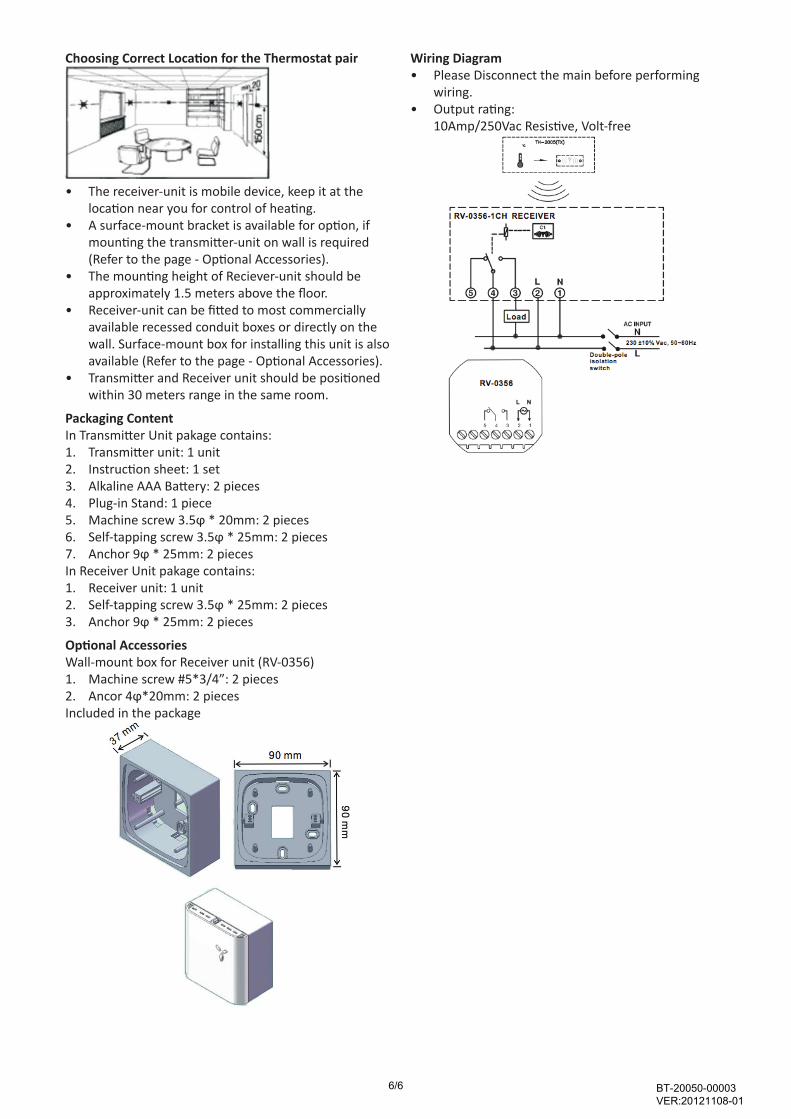
Wiring Diagram• Please Disconnect the main before performing
wiring.• Output rating:
10Amp/250Vac Resistive, Volt-free
6/6 BT-20050-00003 VER:20121108-01