saw head series 700 issue september 2015 page 1 head series 700 issue september 2015 page 3 parts...
TRANSCRIPT
Saw Head Series 700 Issue September 2015 page 1
REMINDER
For any maintenance work on the Saw Head, it is essential to contact your dealer. For optimum performance, use only COUP’ECO spare parts in order to benefit from the latest refinements. Buy your original COUP’ECO parts from your local dealer. Always state the type of machine, its serial number and the reference number of the part. Improvements made by the company may have modified some of the parts listed in the present manual. The most recent part will always be supplied if it is interchangeable with the previous model. Do not hesitate to contact us for any information, as well as for special designs or products.
Saw Head Series 700 Issue September 2015 page 2
Contents
Parts list for a Saw Head model 3700 - welded parts ..................................................................... 3
Parts list for a Saw Head model 4700 - welded parts ..................................................................... 5
Parts list for a Saw Head model 5700 - welded parts ..................................................................... 7
Bearing assembly ........................................................................................................................... 9
Bearings and blades assembly on the case .................................................................................. 11
Coupling assembly – vane motor .................................................................................................. 13
Vane motor equipped .................................................................................................................... 14
Tooling - Mounting / Unmounting blades ...................................................................................... 15
Tooling – removing pulleys ........................................................................................................... 16
Flail blades assembly on reinforced stamped plate ...................................................................... 17
Safety adhesives........................................................................................................................... 18

Saw Head Series 700 Issue September 2015 page 3
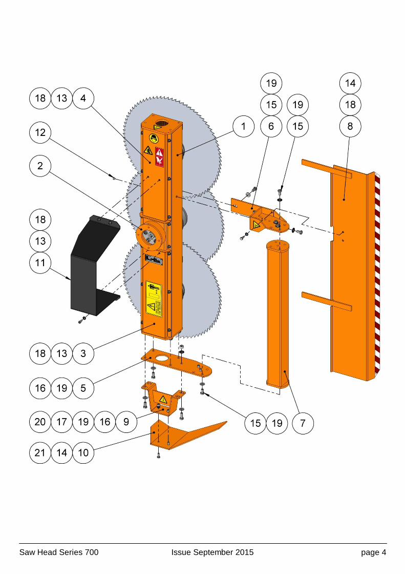
Parts list for a Saw Head model 3700 - welded parts
Item Reference Description Qty
1 40.710.310R Reinforced casing 1
2 30.650.215.02 Motor dome 1
3 14.082.002C.02 Cover 01 1
4 14.082.302C.02 Cover 02 1
5 40.700.009 Mounting 01 - At casing end 1
6 30.650.120 Mounting 02 - On the casing side 1
7 14.080.501 Support tube 100x100 1
8 40.710.315.02 Rear protective casing – right hand mounting 1
40.710.315G Rear protective casing – left hand mounting 1
9 40.700.011 Shoe support 1
10 40.700.012 Shoe – right hand mounting 1
40.700.012G Shoe – left hand mounting 1
11 40.700.019.02 Motor casing – right hand mounting 1
40.700.019G Motor casing – left hand mounting 1
12 21.870.510 Cap 1
13 21.075.802 M 10 x 20 Allen screw 20
14 21.067.802 Hex head 10x25 screw 4
15 21.067.209 Hex head 14x25 screw 9
16 21.067.203 Hex head 14x30 screw 4
17 21.067.206 Hex head 14x35 screw 1
18 21.036.526 10 mm contact washer 24
19 21.036.528 14 mm contact washer 15
20 21.026.507 M14 hex. lock nut 1
21 21.026.505 M10 hex. lock nut 2
Saw Head Series 700 Issue September 2015 page 4

Saw Head Series 700 Issue September 2015 page 5
Parts list for a Saw Head model 4700 - welded parts
Item Reference Description Qty
1 14.088.602R Reinforced casing 1
2 30.650.215.02 Motor dome 1
3 14.082.002C.02 Cover 01 1
4 14.082.003C.02 Cover 02 1
5 40.700.009 Mounting 01 - At casing end 1
6 30.650.120 Mounting 02 - On the casing side 1
7 14.080.501 Support tube 100x100 1
8 40.710.415.02 Rear protective casing 1
9 40.700.011 Shoe support 1
10 40.700.012 Shoe – right hand mounting 1
40.700.012G Shoe – left hand mounting 1
11 40.700.019.02 Motor casing – right hand mounting 1
40.700.019G Motor casing – left hand mounting 1
12 21.870.510 Cap 1
13 21.075.802 M 10 x 20 Allen screw 24
14 21.067.802 Hex head 10x25 screw 4
15 21.067.209 Hex head 14x25 screw 9
16 21.067.203 Hex head 14x30 screw 4
17 21.067.206 Hex head 14x35 screw 1
18 21.036.526 10 mm contact washer 28
19 21.036.528 14 mm contact washer 15
20 21.026.505 M10 hex. lock nut 2
21 21.026.507 M14 hex. lock nut 1
Saw Head Series 700 Issue September 2015 page 6
Saw Head Series 700 Issue September 2015 page 7
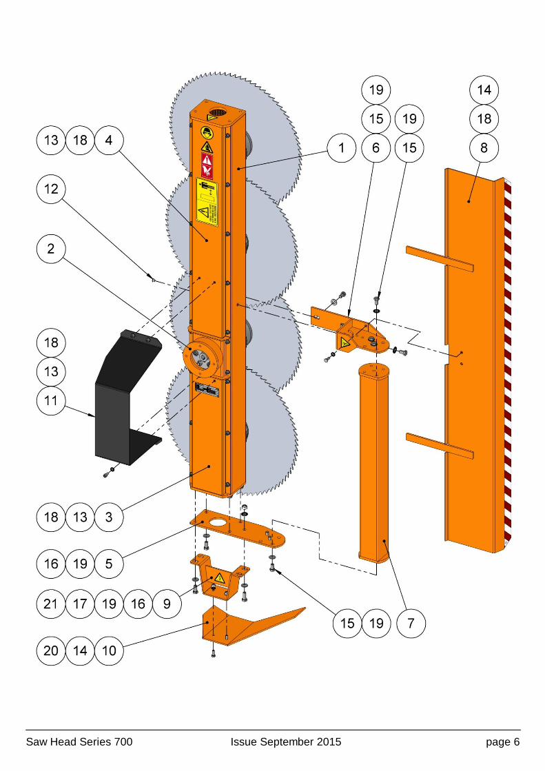
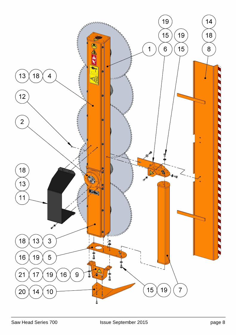
Parts list for a Saw Head model 5700 - welded parts
Item Reference Description Qty
1 14.088.502R Reinforced casing 1
2 30.650.215.02 Motor dome 1
3 14.082.002C.02 Cover 01 1
4 14.082.502 Cover 02 1
5 40.700.009 Mounting 01 - At casing end 1
6 30.650.120 Mounting 02 - On the casing side 1
7 14.080.501 Support tube 100x100 1
8 40.710.515 Rear protective casing 1
9 40.700.011 Shoe support 1
10 40.700.012 Shoe – right hand mounting 1
40.700.012G Shoe – left hand mounting 1
11 40.700.019.02 Motor casing – right hand mounting 1
40.700.019G Motor casing – left hand mounting 1
12 21.870.510 Cap 1
13 21.075.802 M 10 x 20 Allen screw 26
14 21.067.802 Hex head 10x25 screw 4
15 21.067.209 Hex head 14x25 screw 9
16 21.067.203 Hex head 14x30 screw 4
17 21.067.206 Hex head 14x35 screw 1
18 21.036.526 10 mm contact washer 30
19 21.036.528 14 mm contact washer 15
20 21.026.505 M10 hex. lock nut 2
21 21.026.507 M14 hex. lock nut 1
Saw Head Series 700 Issue September 2015 page 8
Saw Head Series 700 Issue September 2015 page 9
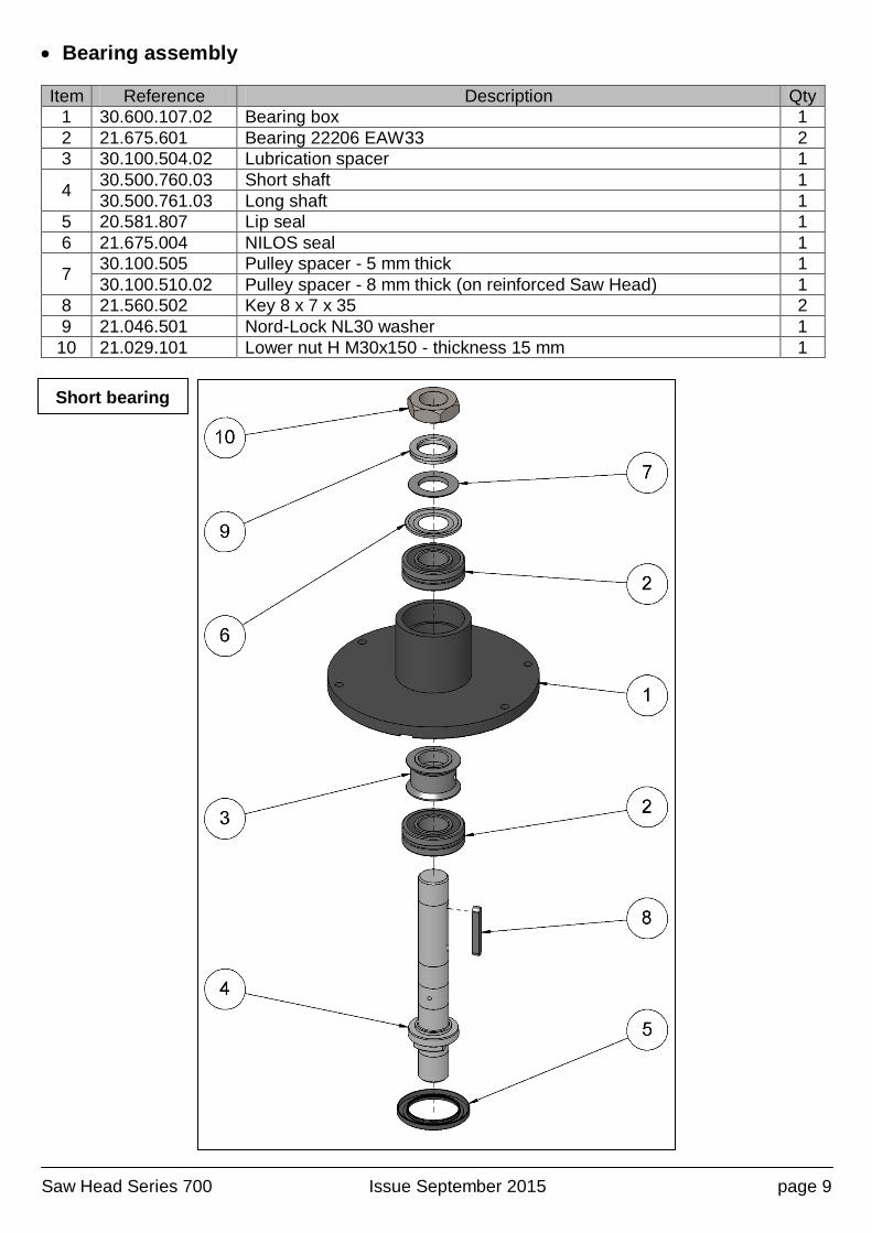
Bearing assembly
Item Reference Description Qty
1 30.600.107.02 Bearing box 1
2 21.675.601 Bearing 22206 EAW33 2
3 30.100.504.02 Lubrication spacer 1
4 30.500.760.03 Short shaft 1
30.500.761.03 Long shaft 1
5 20.581.807 Lip seal 1
6 21.675.004 NILOS seal 1
7 30.100.505 Pulley spacer - 5 mm thick 1
30.100.510.02 Pulley spacer - 8 mm thick (on reinforced Saw Head) 1
8 21.560.502 Key 8 x 7 x 35 2
9 21.046.501 Nord-Lock NL30 washer 1
10 21.029.101 Lower nut H M30x150 - thickness 15 mm 1
Short bearing

Saw Head Series 700 Issue September 2015 page 10
Long bearing
Saw Head Series 700 Issue September 2015 page 11
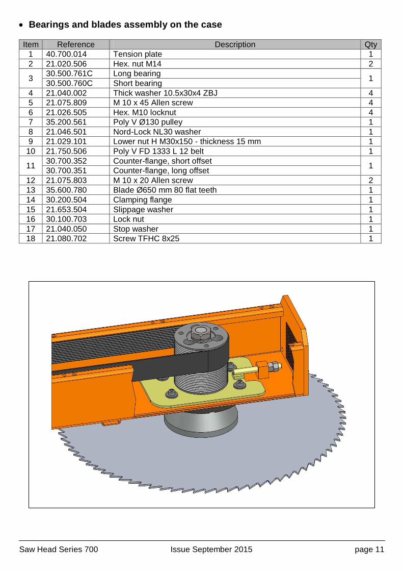
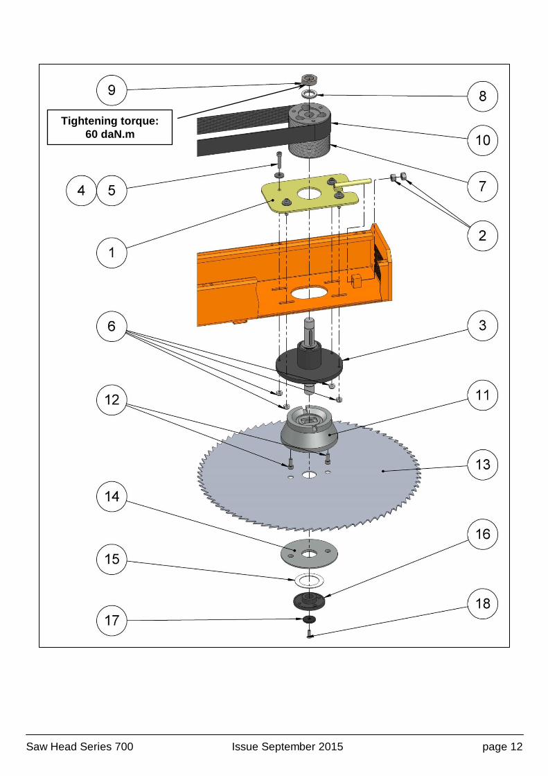
Bearings and blades assembly on the case
Item Reference Description Qty
1 40.700.014 Tension plate 1
2 21.020.506 Hex. nut M14 2
3 30.500.761C Long bearing
1 30.500.760C Short bearing
4 21.040.002 Thick washer 10.5x30x4 ZBJ 4
5 21.075.809 M 10 x 45 Allen screw 4
6 21.026.505 Hex. M10 locknut 4
7 35.200.561 Poly V Ø130 pulley 1
8 21.046.501 Nord-Lock NL30 washer 1
9 21.029.101 Lower nut H M30x150 - thickness 15 mm 1
10 21.750.506 Poly V FD 1333 L 12 belt 1
11 30.700.352 Counter-flange, short offset
1 30.700.351 Counter-flange, long offset
12 21.075.803 M 10 x 20 Allen screw 2
13 35.600.780 Blade Ø650 mm 80 flat teeth 1
14 30.200.504 Clamping flange 1
15 21.653.504 Slippage washer 1
16 30.100.703 Lock nut 1
17 21.040.050 Stop washer 1
18 21.080.702 Screw TFHC 8x25 1
Saw Head Series 700 Issue September 2015 page 12
Tightening torque:
60 daN.m

Saw Head Series 700 Issue September 2015 page 13
Coupling assembly – vane motor
Item Reference Description Qty
1 30.100.553 Coupling spacer 3
2 - Complete coupling 1
2.1 30.501.558 Coupling half 1
2.2 21.667.506 Bushing 1
2.3 21.075.202 M 14 x 50 Allen screw 3
2.4 21.026.507 M14 Hex. lock nut 3
2.5 21.550.503 Inner circlips 1
3 21.075.205 M 14 x 55 Allen screw 3
4 30.650.215.02 Motor dome 1
5 21.075.802 M 10 x 20 Allen screw 4
6 21.036.526 10 mm contact washer 4
7 21.620.703C Vane motor 31.5 cm³ + pressure limiter units 1
21.620.702C Vane motor 43.9 cm³ + pressure limiter units 1
8 21.036.525 12 mm contact washer 2
9 21.067.100 Hex head 12x25 screw 2
10 21.075.601 M 6 x 10 Allen screw 1
11 GPN.900.165 Caps Ø16.5 x 9 1
Saw Head Series 700 Issue September 2015 page 14
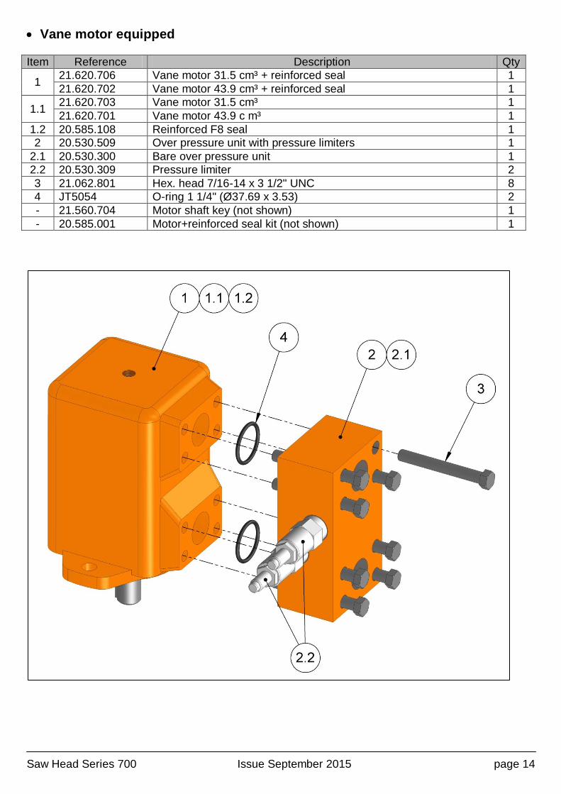
Vane motor equipped
Item Reference Description Qty
1 21.620.706 Vane motor 31.5 cm³ + reinforced seal 1
21.620.702 Vane motor 43.9 cm³ + reinforced seal 1
1.1 21.620.703 Vane motor 31.5 cm³ 1
21.620.701 Vane motor 43.9 c m³ 1
1.2 20.585.108 Reinforced F8 seal 1
2 20.530.509 Over pressure unit with pressure limiters 1
2.1 20.530.300 Bare over pressure unit 1
2.2 20.530.309 Pressure limiter 2
3 21.062.801 Hex. head 7/16-14 x 3 1/2" UNC 8
4 JT5054 O-ring 1 1/4" (Ø37.69 x 3.53) 2
- 21.560.704 Motor shaft key (not shown) 1
- 20.585.001 Motor+reinforced seal kit (not shown) 1

Saw Head Series 700 Issue September 2015 page 15
Tooling - Mounting / Unmounting blades
Item Reference Description Qty
1 30.700.755 Lock pin 1
2 30.650.116 Saw head tightening wrench 1
3 21.065.940 M 12 x 20 Allen screw 2
4 30.700.750 A 5mm Allen wrench 4
5 21.886.005 Straight M8x125 grease nipple (for greasing bearings) 1
5
Saw Head Series 700 Issue September 2015 page 16
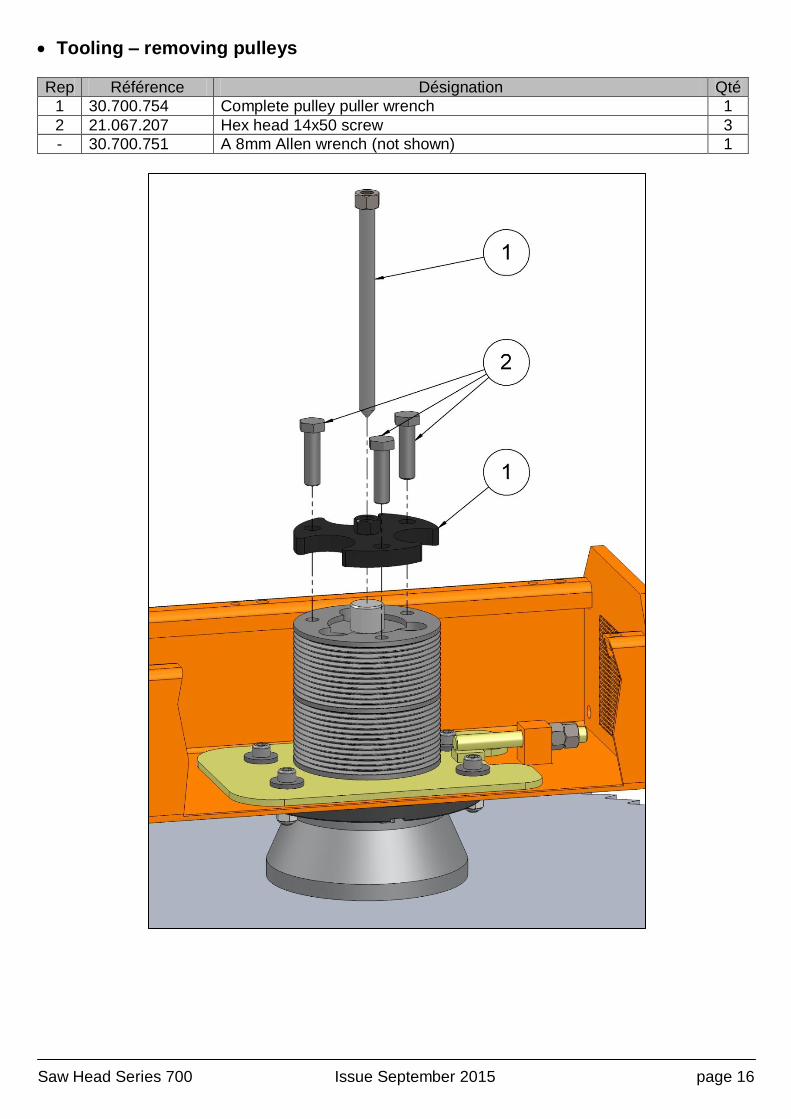
Tooling – removing pulleys
Rep Référence Désignation Qté
1 30.700.754 Complete pulley puller wrench 1
2 21.067.207 Hex head 14x50 screw 3
- 30.700.751 A 8mm Allen wrench (not shown) 1
Saw Head Series 700 Issue September 2015 page 17
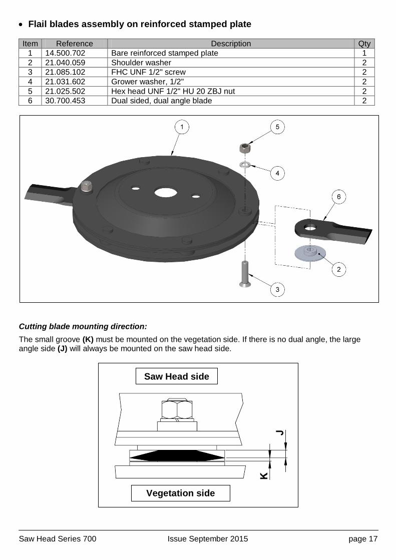
Flail blades assembly on reinforced stamped plate
Item Reference Description Qty
1 14.500.702 Bare reinforced stamped plate 1
2 21.040.059 Shoulder washer 2
3 21.085.102 FHC UNF 1/2" screw 2
4 21.031.602 Grower washer, 1/2" 2
5 21.025.502 Hex head UNF 1/2" HU 20 ZBJ nut 2
6 30.700.453 Dual sided, dual angle blade 2
Cutting blade mounting direction:
The small groove (K) must be mounted on the vegetation side. If there is no dual angle, the large angle side (J) will always be mounted on the saw head side.
Saw Head side
Vegetation side
Saw Head Series 700 Issue September 2015 page 18
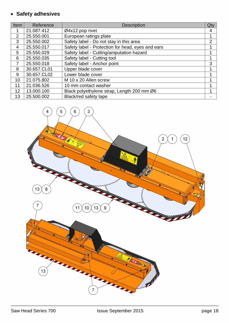
Safety adhesives
Item Reference Description Qty
1 21.087.412 Ø4x12 pop rivet 4
2 25.550.001 European ratings plate 1
3 25.550.002 Safety label - Do not stay in this area 2
4 25.550.017 Safety label - Protection for head, eyes and ears 1
5 25.550.029 Safety label - Cutting/amputation hazard 1
6 25.550.035 Safety label - Cutting tool 1
7 25.550.018 Safety label - Anchor point 3
8 30.657.CL01 Upper blade cover 1
9 30.657.CL02 Lower blade cover 1
10 21.075.802 M 10 x 20 Allen screw 1
11 21.036.526 10 mm contact washer 1
12 13.000.100 Black polyethylene strap, Length 200 mm Ø6 1
13 25.500.002 Black/red safety tape -
contactus www.noremat.fr
CONTACT
Dynapôle Ludres/Fléville - 166, rue AmpèreBP 6009354714 LUDRES Cedex - FRANCE
Tél. : +33 (0)3 83 25 96 12 - Fax : +33 (0)3 83 26 12 85
05
04 06
8313
84
48
30
34
11
66 2B
2A
17 16
64
40
3324
87
47
14
61
50
2953
22
56
35
72
27
76
44 3749
858679
62
80
9070
25
6002
51 5557
54
67
688852
59
08
28
4541
36
18 58
89
21
77
9575
1091
78
39
74
73
01
69
38
2607
71
12
81
09
46
82
32
31
65
4223
19
63
03
4315