scada / glt connection for fp gateways manual
TRANSCRIPT
FP SCADA / GLT Manual - EN
SCADA / GLT Connection for FP Gateways Manual
Version: 1.6.1 © 2018 -2021 FP InovoLabs GmbH
www.inovolabs.com Publication date: 23/02/2021
This manual is protected by copyright. Any further dissemination is only permitted with permission from the issuer. This also applies to copies, microfilms, translations, and storing and processing in electronic systems. Trade and brand names used in this manual are registered trademarks of the applicable companies even if they are not designated as such explicitly.
51.0058.9206.01 Rev.01 FP SCADA / GLT Manual
2
Table of contents
1 INTRODUCTION ........................................................................................................................... 3
1.1 FP gateway short description ..................................................................................................................... 3 1.1.1 Interfaces and field buses ............................................................................................................................... 3 1.1.2 Overview of main functions ............................................................................................................................ 4
1.2 GLT / SCADA short description ................................................................................................................... 4
2 COMMUNICATION OPTIONS ....................................................................................................... 5
2.1 Pull – collecting and writing data ............................................................................................................... 5 2.1.1 via TiXML ......................................................................................................................................................... 5 2.1.2 via HTTP .......................................................................................................................................................... 8
2.1.2.1 Reading values ....................................................................................................................................... 9 2.1.2.2 Reading the configuration .................................................................................................................... 10 2.1.2.3 Reading log files ................................................................................................................................... 11 2.1.2.4 Writing individual values ...................................................................................................................... 12 2.1.2.5 Writing several database entries ......................................................................................................... 12 2.1.2.6 Calling functions ................................................................................................................................... 12
2.2 Push – receiving data ............................................................................................................................... 13 2.2.1 via e-mail ....................................................................................................................................................... 13 2.2.2 via HTTP ........................................................................................................................................................ 13
2.3 Using the TiXML interface via http POST (TiXML.cgi) ................................................................................ 14
3 APPENDIX .................................................................................................................................. 16
3.1 URL examples .......................................................................................................................................... 16
3.2 TDG system data ..................................................................................................................................... 16
3.3 M-bus configuration ................................................................................................................................ 19
51.0058.9206.01 Rev.01 FP SCADA / GLT Manual
3 Introduction
1 Introduction ______________________________________________________________________________________
This manual describes the communication interfaces between an FP gateway and a building control system (GLT) or a SCADA system to store, prepare and display data.
The GLT has read access to the following data:
- Current PLC, meter or I/O data points, - Historical PLC, meter or I/O data points from the TDG log memory, - Current system data for the TDG, - Current configuration data for the TDG.
The GLT has write access to the following data:
- Current PLC, meter or I/O data points, - Individual configuration entries, - Complete configurations (via TiXML).
1.1 FP gateway short description The direct connection option for the FP gateways to virtually any small or large controller and many meter types heralds a new era for simple and low-cost remote maintenance solutions for industry. The 80 MB data memory is non-volatile (Flash technology).
The FP gateway is configured via TiXML (optimised XML) and also uses TiXML to store data and to exchange data.
1.1.1 Interfaces and field buses Up to 4 field buses can be connected to FP gateways and each field bus can use a different protocol, for ex-ample:
Bus1 on COM1 RS232 Moeller EASY small PLC Bus2 on COM2 RS485 MODBUS with several PLCs, e.g. ABB, Mitsubishi Bus3 on COM3 M-bus 10 different meters for electricity, gas, water, heat Bus4 on COM4 RS485 Radio temperature sensor system
An infinite number of stations or devices can be connected to each bus depending on which the bus proto-col permits. Each device on the bus can have parameters or variables.
The FP gateway lays out the different bus systems, devices and variables in a hierarchical data model with the hierarchy levels
/Process/BusX/Device_X/Variable_X
Example Process Bus1 Device_1 Variable_1 Variable_2 ....... Device_2 ..... Bus2 Device_1 ...... The entire bus, a device or a variable is always accessed via this path specification.
51.0058.9206.01 Rev.01 FP SCADA / GLT Manual
4 Introduction
1.1.2 Overview of main functions
- FP gateways are available as LAN and mobile communications variants - PLC protocols from leading PLC manufacturers are already integrated - adaptation without repro-
gramming the PLC - Alerting with acknowledgement and alarm cascades by e-mail - Telecontrol by e-mail, integrated web server and via the cloud - Calendar, e.g. to use shift schedules when alerting - Data logging including automatable data sending by e-mail - Data sequencer for time-dependent control, e.g. by specifying a value curve for 1 year with 15 minute values and comparing the current Tixi values with this curve - Event-based system - Embedded web server for data presentation and to control individual parameters
1.2 GLT / SCADA short description A GLT is used to manage systems and data, and to display the data for PLCs, control system, energy meters and the intelligent FP gateways, which can be used via the FP gateway.
In addition to reading and writing individual field data, log files and data to maintain a machine folder are possible. The configuration data for all FP gateways should also be managed in the GLT.
In order to ensure that a GLT has access to this data, the access options for the end devices must be de-signed and implemented. The interfaces that can be used for this are explained in the following.
The GLT or SCADA system is designated as “Server” below.
51.0058.9206.01 Rev.01 FP SCADA / GLT Manual
5 Communication options
2 Communication options ______________________________________________________________________________________
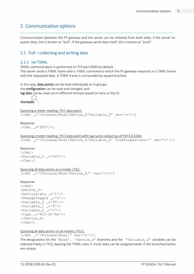
Communication between the FP gateway and the server can be initiated from both sides. If the server re-quests data, this is known as “pull”; if the gateway sends data itself, this is known as “push”.
2.1 Pull – collecting and writing data
2.1.1 via TiXML TiXML communication is performed on TCP port 8300 by default. The server sends a TiXML frame with a TiXML command to which the FP gateway responds in a TiXML frame with the requested data. A TiXML frame is surrounded by square brackets. In this way, data points can be read individually or in groups, the configuration can be read and changed, and log data can be read out in different formats based on time or the ID. Examples Querying a meter reading / PLC data point: [<Get _="/Process/Bus1/Device_0/Variable_0" ver="v"/>] Response: [<Get _="200"/>] Querying a meter reading / PLC data point with tag name output (as of FW 3.0.6.84): [<Get _="/Process/Bus1/Device_0/Variable_0" ViewProperties="" ver="v"/>] Response: [<Get> <Variable_0 _="200"/> </Get>] Querying all data points on a meter / PLC: [<Get _="/Process/Bus1/Device_0/" ver="v"/>] Response: [<Get> <Device_0> <DeviceState _="1"/> <ChangeToggle _="0"/> <Variable_0 _="95"/> <Variable_1 _="0"/> <Variable_2 _="1"/> <Type _="412-DC-Rx"/> </Device_0> </Get>] Querying all data points on all meters / PLCs: [<Get _="/Process/Bus1/" ver="v"/>] The designations for the "BusX", "Device_X" branches and the "Variable_X" variables can be selected freely in TICO, bearing the TiXML rules in mind; data can be assigned easier if the branches/names are unique.
51.0058.9206.01 Rev.01 FP SCADA / GLT Manual
6 Communication options
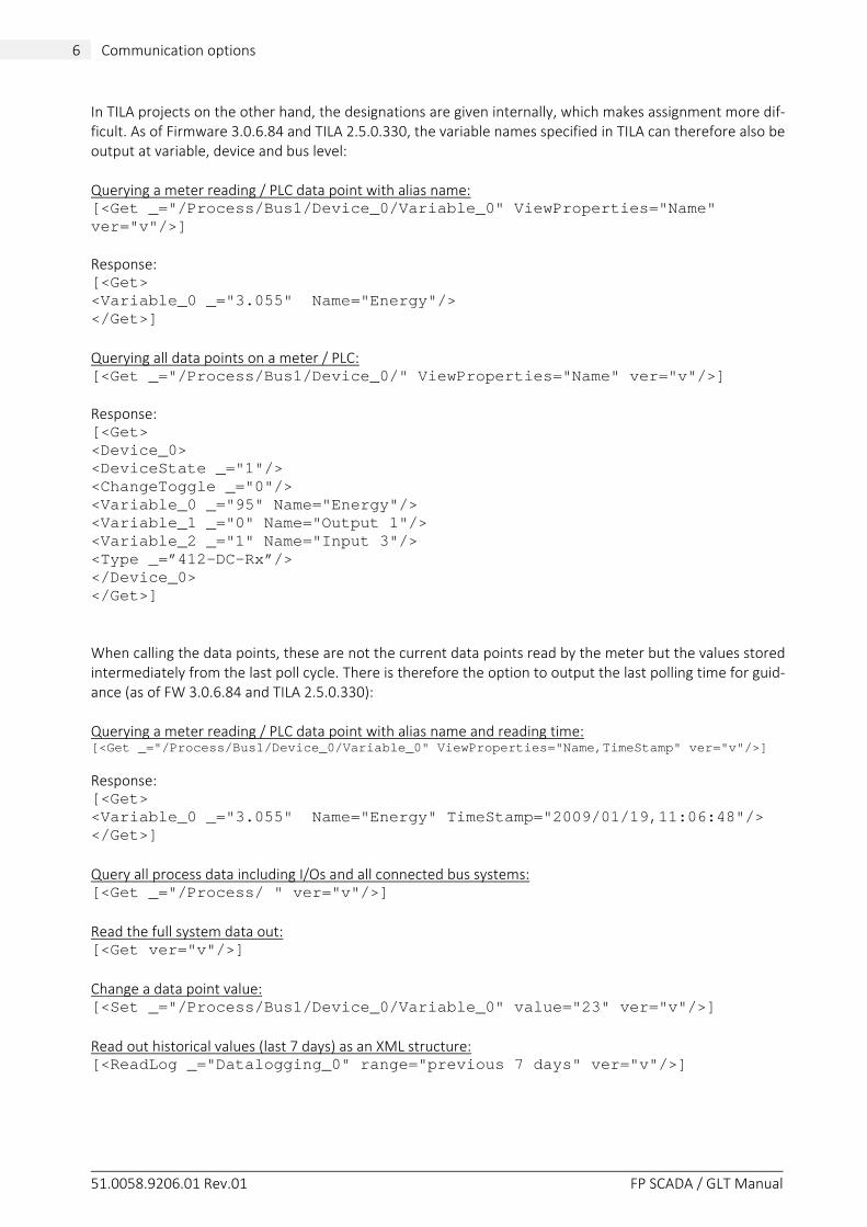
In TILA projects on the other hand, the designations are given internally, which makes assignment more dif-ficult. As of Firmware 3.0.6.84 and TILA 2.5.0.330, the variable names specified in TILA can therefore also be output at variable, device and bus level: Querying a meter reading / PLC data point with alias name: [<Get _="/Process/Bus1/Device_0/Variable_0" ViewProperties="Name" ver="v"/>] Response: [<Get> <Variable_0 _="3.055" Name="Energy"/> </Get>] Querying all data points on a meter / PLC: [<Get _="/Process/Bus1/Device_0/" ViewProperties="Name" ver="v"/>] Response: [<Get> <Device_0> <DeviceState _="1"/> <ChangeToggle _="0"/> <Variable_0 _="95" Name="Energy"/> <Variable_1 _="0" Name="Output 1"/> <Variable_2 _="1" Name="Input 3"/> <Type _=”412-DC-Rx”/> </Device_0> </Get>] When calling the data points, these are not the current data points read by the meter but the values stored intermediately from the last poll cycle. There is therefore the option to output the last polling time for guid-ance (as of FW 3.0.6.84 and TILA 2.5.0.330): Querying a meter reading / PLC data point with alias name and reading time: [<Get _="/Process/Bus1/Device_0/Variable_0" ViewProperties="Name,TimeStamp" ver="v"/>]
Response: [<Get> <Variable_0 _="3.055" Name="Energy" TimeStamp="2009/01/19,11:06:48"/> </Get>] Query all process data including I/Os and all connected bus systems: [<Get _="/Process/ " ver="v"/>] Read the full system data out: [<Get ver="v"/>] Change a data point value: [<Set _="/Process/Bus1/Device_0/Variable_0" value="23" ver="v"/>] Read out historical values (last 7 days) as an XML structure: [<ReadLog _="Datalogging_0" range="previous 7 days" ver="v"/>]
51.0058.9206.01 Rev.01 FP SCADA / GLT Manual
7 Communication options
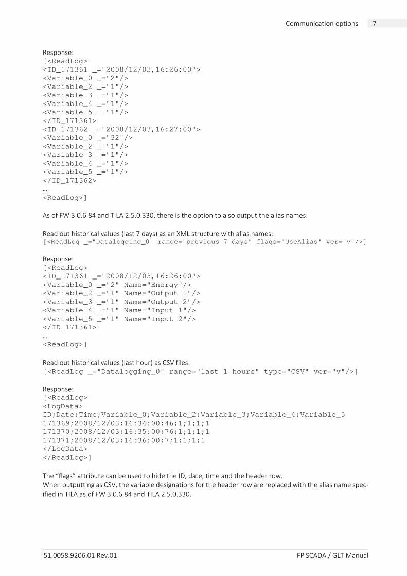
Response: [<ReadLog> <ID_171361 _="2008/12/03,16:26:00"> <Variable_0 _="2"/> <Variable_2 _="1"/> <Variable_3 _="1"/> <Variable_4 _="1"/> <Variable_5 _="1"/> </ID_171361> <ID_171362 _="2008/12/03,16:27:00"> <Variable_0 _="32"/> <Variable_2 _="1"/> <Variable_3 _="1"/> <Variable_4 _="1"/> <Variable_5 _="1"/> </ID_171362> … <ReadLog>] As of FW 3.0.6.84 and TILA 2.5.0.330, there is the option to also output the alias names: Read out historical values (last 7 days) as an XML structure with alias names: [<ReadLog _="Datalogging_0" range="previous 7 days" flags="UseAlias" ver="v"/>] Response: [<ReadLog> <ID_171361 _="2008/12/03,16:26:00"> <Variable_0 _="2" Name="Energy"/> <Variable_2 _="1" Name="Output 1"/> <Variable_3 _="1" Name="Output 2"/> <Variable_4 _="1" Name="Input 1"/> <Variable_5 _="1" Name="Input 2"/> </ID_171361> … <ReadLog>] Read out historical values (last hour) as CSV files: [<ReadLog _="Datalogging_0" range="last 1 hours" type="CSV" ver="v"/>] Response: [<ReadLog> <LogData> ID;Date;Time;Variable_0;Variable_2;Variable_3;Variable_4;Variable_5 171369;2008/12/03;16:34:00;46;1;1;1;1 171370;2008/12/03;16:35:00;76;1;1;1;1 171371;2008/12/03;16:36:00;7;1;1;1;1 </LogData> </ReadLog>] The “flags” attribute can be used to hide the ID, date, time and the header row. When outputting as CSV, the variable designations for the header row are replaced with the alias name spec-ified in TILA as of FW 3.0.6.84 and TILA 2.5.0.330.
51.0058.9206.01 Rev.01 FP SCADA / GLT Manual
8 Communication options
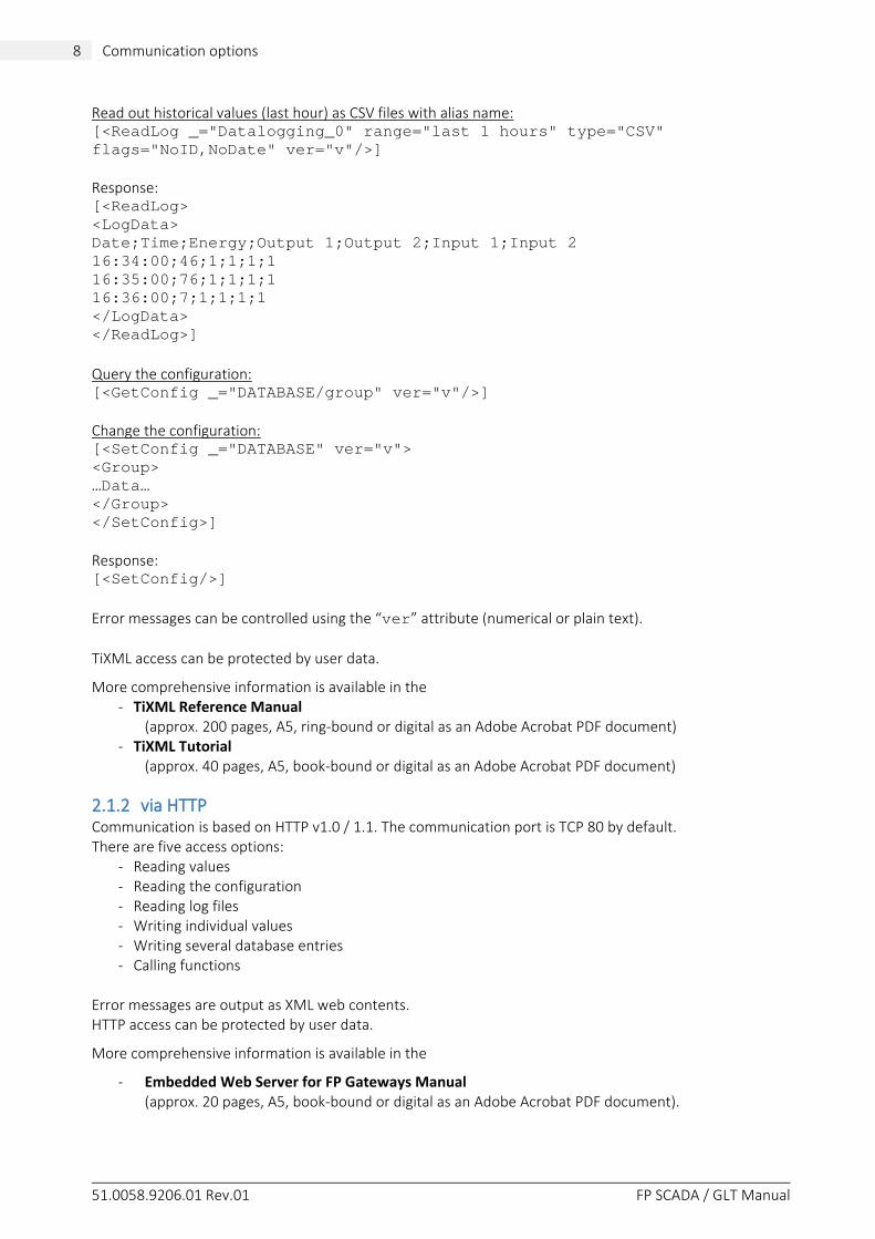
Read out historical values (last hour) as CSV files with alias name: [<ReadLog _="Datalogging_0" range="last 1 hours" type="CSV" flags="NoID,NoDate" ver="v"/>] Response: [<ReadLog> <LogData> Date;Time;Energy;Output 1;Output 2;Input 1;Input 2 16:34:00;46;1;1;1;1 16:35:00;76;1;1;1;1 16:36:00;7;1;1;1;1 </LogData> </ReadLog>] Query the configuration: [<GetConfig _="DATABASE/group" ver="v"/>] Change the configuration: [<SetConfig _="DATABASE" ver="v"> <Group> …Data… </Group> </SetConfig>] Response: [<SetConfig/>] Error messages can be controlled using the “ver” attribute (numerical or plain text). TiXML access can be protected by user data.
More comprehensive information is available in the - TiXML Reference Manual
(approx. 200 pages, A5, ring-bound or digital as an Adobe Acrobat PDF document) - TiXML Tutorial
(approx. 40 pages, A5, book-bound or digital as an Adobe Acrobat PDF document)
2.1.2 via HTTP Communication is based on HTTP v1.0 / 1.1. The communication port is TCP 80 by default. There are five access options:
- Reading values - Reading the configuration - Reading log files - Writing individual values - Writing several database entries - Calling functions
Error messages are output as XML web contents. HTTP access can be protected by user data.
More comprehensive information is available in the
- Embedded Web Server for FP Gateways Manual (approx. 20 pages, A5, book-bound or digital as an Adobe Acrobat PDF document).
51.0058.9206.01 Rev.01 FP SCADA / GLT Manual
9 Communication options
2.1.2.1 Reading values You can access the system data as follows: http://<TDG-IP>/System/Properties/<PropertyPath>
- <TDG-IP> is the TDG IP address; - <PropertyPath> is the path for a system property
Note: The system distinguishes between uppercase and lowercase in path specifications.
The response is output as XML web contents with the XML name <?xml version="1.0"?>.
Examples Querying a meter reading / PLC data point: http://<TDG-IP>/System/Properties/Process/Bus1/Device_0/Variable_0 Response: <?xml version="1.0"?> <Variable_0 _="200"/> Querying all data points on a meter / PLC: http://<TDG-IP>/System/Properties/Process/Bus1/Device_0/ Response: <?xml version="1.0"?> <Device_0> <DeviceState _="1"/> <ChangeToggle _="0"/> <Variable_0 _="95"/> <Variable_1 _="0"/> <Variable_2 _="1"/> <Type _="412-DC-Rx"/> </Device_0> Querying all data points on all meters / PLCs on a bus: http://<TDG-IP>/System/Properties/Process/Bus1/ The designations for the "BusX", "Device_X" branches and the "Variable_X" variables can be selected freely in TICO, bearing the TiXML rules in mind; data can be assigned easier if the branches/names are unique. In TILA projects on the other hand, the designations are given internally, which makes assignment more dif-ficult. As of Firmware 3.0.6.84 and TILA 2.5.0.330, the variable names specified in TILA can therefore also be output at variable, device and bus level: Querying a meter reading / PLC data point with alias name: http://<TDG-IP>/System/Properties/Process/Bus1/Device_0/Variable_0?ViewProperties=Name Response: <?xml version="1.0"?> <Variable_0 _="200" Name="Energy"/>
51.0058.9206.01 Rev.01 FP SCADA / GLT Manual
10 Communication options
Querying all data points on a meter / PLC with alias name: http://<TDG-IP>/System/Properties/Process/Bus1/Device_0/?ViewProperties=Name Response: <?xml version="1.0"?> <Device_0> <DeviceState _="1"/> <ChangeToggle _="0"/> <Variable_0 _="95" Name="Energy"/> <Variable_1 _="0" Name="Output 1"/> <Variable_2 _="1" Name="Input 1"/> <Type _="412-DC-Rx"/> </Device_0> When calling the data points, these are not the current data points read by the meter but the values stored intermediately from the last poll cycle. There is therefore the option to output the last polling time for guid-ance (as of FW 3.0.6.84 and TILA 2.5.0.330): Querying a meter reading / PLC data point with alias name and reading time: http://<TDG-IP>/System/Properties/Process/Bus1/Device_0/Variable_0?ViewProperties=Name,TimeStamp Response: <?xml version="1.0"?> <Variable_0 _="200" Name="Energy" TimeStamp="2009/01/19,11:06:48"/> Query all process data including I/Os and all connected bus systems: http://<TDG-IP>/System/Properties/Process/ Read the full system data out: http://<TDG-IP>/System/Properties/ Response: see section 3.2 If you wish to query individual data points without an XML structure, this is possible using a CGI, e.g.: http://<TDG-IP>/cgi-bin/readVal.exe?/Process/Bus1/Device_0/Variable_0 The server outputs the raw value as a MIME type text/plain, e.g. “200”.
2.1.2.2 Reading the configuration In the same way as reading system data, the configuration data for maintaining the machine folder can be accessed: http://<TDG-IP>/System/Config/<PropertyPath>
- <TDG-IP> is the TDG IP address; - <PropertyPath> is the path for a configuration property.
Example http://<TDG-IP>/System/Config/PROCCFG/External XML web contents with all of the PLC / meter connection configuration data are output.
51.0058.9206.01 Rev.01 FP SCADA / GLT Manual
11 Communication options
2.1.2.3 Reading log files A CGI can be used to call the historical data collected by the TDG; either predefined format templates (XML, CSV) can be used or you can configure the structure yourself within a certain framework. XML data is called directly using the log file name: http://<TDG-IP>/System/Config/PROCCFG/External/ CSV and user-defined formats are called using alias formatting: http://<TDG-IP>/cgi-bin/readLog.exe?<Logfile-Aliasname>+<Range> As of Firmware 3.0.6.84 and TILA 2.5.0.330, there is the option to output the alias names for the variables.
Specifying <Range> is essential and must be performed as described in the TiXML Reference Manual.
Examples Read the full “Datalogging_0” log file out: http://<TDG-IP>/cgi-bin/readLog.exe?Datalogging_0+all Response: <?xml version="1.0"?> <Datalogging_0> <ID_171361 _="2008/12/03,16:26:00"> <Variable_0 _="2"/> <Variable_2 _="1"/> <Variable_3 _="1"/> <Variable_4 _="1"/> <Variable_5 _="1"/> </ID_171361> <ID_171362 _="2008/12/03,16:27:00"> <Variable_0 _="32"/> <Variable_2 _="1"/> <Variable_3 _="1"/> <Variable_4 _="1"/> <Variable_5 _="1"/> </ID_171362> <ID_171363 _="2008/12/03,16:28:00"> <Variable_0 _="63"/> <Variable_2 _="1"/> <Variable_3 _="1"/> <Variable_4 _="1"/> <Variable_5 _="1"/> </ID_171363> </Datalogging_0> Read out historical values (last hour) as CSV files: http://<TDG-IP>/cgi-bin/readLog.exe?Datalogging_0_CSV+last%201%20hours
(last 1 hour, %20 = space)
The server outputs the data as a MIME type text/plain:
ID;Date;Time;Variable_0;Variable_2;Variable_3;Variable_4;Variable_5 171369;2008/12/03;16:34:00;46;1;1;1;1 171370;2008/12/03;16:35:00;76;1;1;1;1 171371;2008/12/03;16:36:00;7;1;1;1;1 When outputting as CSV, the variable designations for the header row are replaced with the alias name spec-ified in TILA as of FW 3.0.6.84 and TILA 2.5.0.330.
51.0058.9206.01 Rev.01 FP SCADA / GLT Manual
12 Communication options
2.1.2.4 Writing individual values Data points can be written individually via a CGI: http://<TDG-IP>/cgi-bin/writeVal.exe?<Path>+<value>
Example http://<TDG-IP>/cgi-bin/writeVal.exe?/Process/Bus1/Device_0/Variable_0+23
2.1.2.5 Writing several database entries If you wish to write several data points at the same time, write access can be provided via an http POST, as it generates a form for example: <FORM method="POST" target="NullDevice"> <INPUT type="hidden" name="section" value="Form1"> <INPUT type="text" name="Value1" value=""/> <INPUT type="text" name="Value2" value=""/> <INPUT type="text" name="Value3" value=""/> <INPUT class="button" type="submit" value="submit"/> </FORM> The "section" hidden field generates a "value" section in the PARAM database ("Form1" in the example). This field must be the first field in the form or POST! The form fields are transferred to the section as individual data elements. The result of the example would match the following TiXML command: [<SetConfig _="PARAM" ver="v"> <WebForms> <Form1> <Value1 _="xzy"/> <Value2 _="xzy"/> <Value3 _="xzy"/> </Form1> </WebForms> </SetConfig>]
2.1.2.6 Calling functions The FP gateway provides a CGI to call functions (event handlers). For example, data sending by e-mail can be triggered or up to 10 data points can be written via http GET. http://<TDG-IP>/cgi-bin/DoOn.exe?Eventhandler+P1+P2+P3+P4+P5+P6+P7+P8+P9+P10 Responses: 2 --> waiting for execution 1 --> execution running 0 --> execution OK Error number --> see the TiXML Reference Manual The return is provided in the event of OK/error immediately or after 4s if processing does not start immedi-ately (--> 2).
51.0058.9206.01 Rev.01 FP SCADA / GLT Manual
13 Communication options
2.2 Push – receiving data
2.2.1 via e-mail The FP gateway can send current and historical data in the form of e-mails. The message text can always be configured freely and contain current variable values via references. Historical data is sent in the form of e-mail attachments; either predefined format templates (XML, CSV) can be used or you can configure the structure yourself within a certain framework. Example (CSV attachments with parameters set using TILA) Date;time;energy;volume;supply temp;return temp;difference temp;flow rate 27.09.2008;11:00:00;0;0.0191;0.099;0.1;0.1;0 27.09.2008;12:00:00;0;0.0191;0.099;0.1;0.1;0 27.09.2008;13:00:00;0;0.019;0.099;0.1;0.1;0 27.09.2008;14:00:00;0;0.0189;0.099;0.1;0.1;0
2.2.2 via HTTP The FP gateway is able to send current values as an http request using the “GET” method. These can be managed and forwarded in a centralised manner there.
This section uses an example to describe how to use the TICO software to configure such an “HTTP notifica-tion”. Knowledge of the FP gateway’s internal process sequences is required. Creating an event handler for the notification: [<SetConfig _="EVENTS" ver="y"> <EventHandler> <HTTP> <SendMail _="MessageJobTemplates/HTTP"/> </HTTP> </EventHandler> </SetConfig>] Creating a message template: [<SetConfig _="TEMPLATE" ver="y"> <MessageJobTemplates> <HTTP _="URLSend"> <Recipient _="/D/AddressBook/Contact_0"/> </HTTP> </MessageJobTemplates> </SetConfig>] Creating the URL in the address book The URL can contain one or several variables that are formed by references (®/path). There is the option to specify the server's http port and an authentication. [<SetConfig _="TEMPLATE" ver="y"> <AddressBook> <Contact_0> <URL _="http://glt.tixi.com/cgi-bin/writeData.cgi ?Variable_0=®/Process/Bus1/Device_0/Variable_0"/> <URLPort _="80"/> <User _="DH"/> <Password _="pwd"/>
51.0058.9206.01 Rev.01 FP SCADA / GLT Manual
14 Communication options
</Contact_0> </AddressBook> </SetConfig>] This example calls the following HTTP notification URL (if variable_0=20): http://glt.tixi.com/cgi-bin/writeData.cgi?Variable_0=20 Example (HTTP recording) GET /cgi-bin/writeData.cgi?Variable_0=20 HTTP/1.1 Authorization: Basic VGl4aW5ldGdlYXI6VGl4aU1haWxCb3g=
2.3 Using the TiXML interface via http POST (TiXML.cgi) The TiXML interface that is used via the TICO and TILA software to configure the FP gateways can also be used via http POST. To do this, the TiXML.cgi cgi command is implemented in the FP gateways. This inter-face can be used to send all TiXML commands to the FP gateway, for example:
- Uploading a new / changed configuration - Querying the configuration - Reading log files - Triggering events
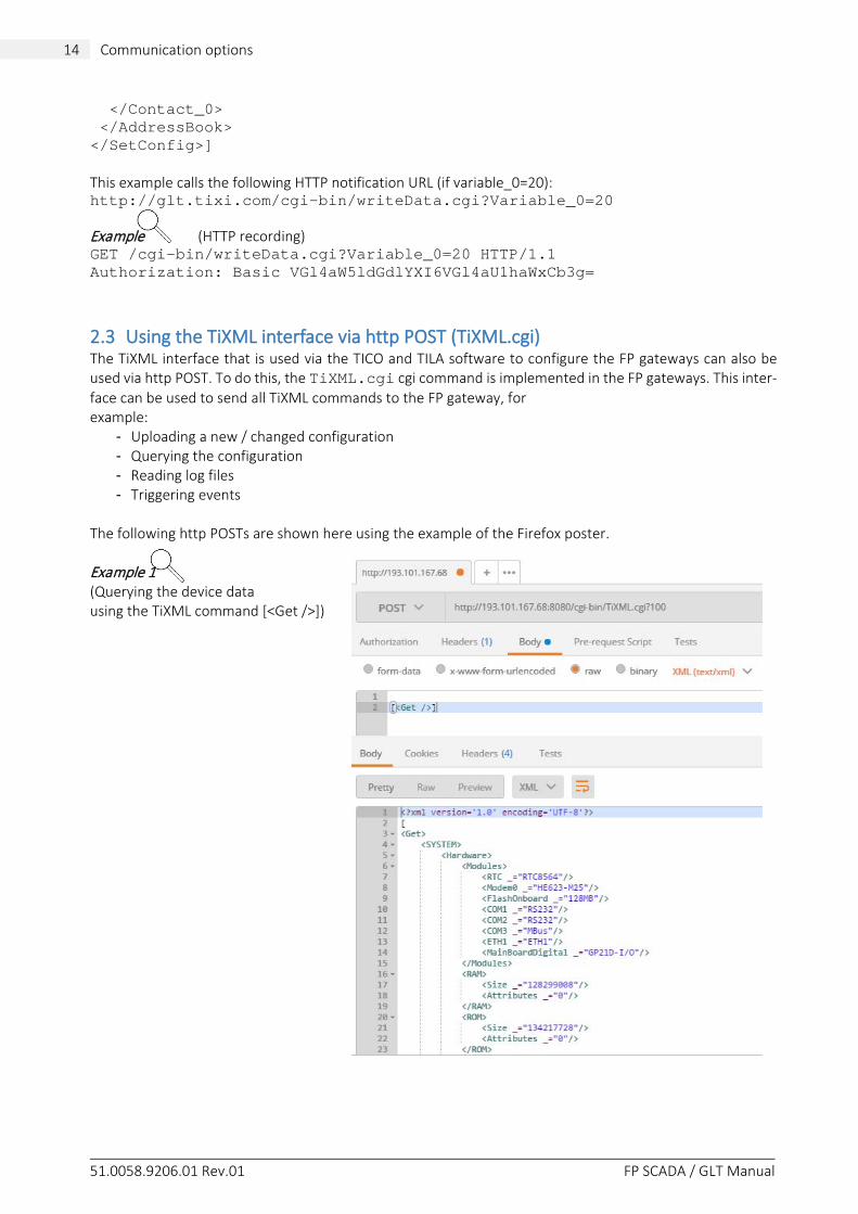
The following http POSTs are shown here using the example of the Firefox poster. Example 1 (Querying the device data using the TiXML command [<Get />])
51.0058.9206.01 Rev.01 FP SCADA / GLT Manual
15 Communication options
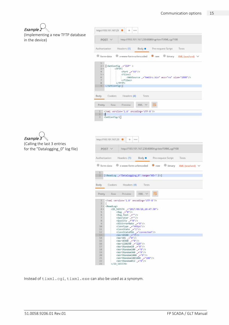
Example 2 (Implementing a new TFTP database in the device) Example 3 (Calling the last 3 entries for the "Datalogging_0" log file) Instead of tixml.cgi, tixml.exe can also be used as a synonym.
51.0058.9206.01 Rev.01 FP SCADA / GLT Manual
16 Appendix
3 Appendix ______________________________________________________________________________________
3.1 URL examples The following are some HTTP links to TiXML data structures for direct testing. Hardware and system data http://193.101.167.68:8080/System/Properties/ Date and time http://193.101.167.68:8080/System/Properties/TIMES/RFC822Date File system memory http://193.101.167.68:8080/System/Properties/Hardware/FileSystem/Size PLC data http://193.101.167.68:8080/System/Properties/Process/Bus1/Device_0/ Complete TDG configuration http://193.101.167.68:8080/System/Config/ Data logging configuration http://193.101.167.68:8080/System/Config/LOG/LogDefinition/ PLC configuration http://193.101.167.68:8080/System/Config/PROCCFG/External/
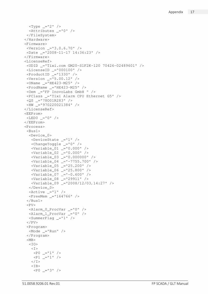
3.2 TDG system data The complete system branch for an HE423-M25 with an M-bus meter connected is shown here: <SYSTEM> <Hardware> <Modules> <RTC _="RTC8564" /> <Modem0 _="HE423-M25" /> <FlashOnboard _="6MB" /> <PowerSupply _="2.0A" /> <COM1 _="RS232 (Host)" /> <COM2 _="RS232" /> <COM3 _="MBUS" /> <ETH1 _="DM9000 (Rev. 19)" /> <MBDIO _="GP21D-I/O" /> </Modules> <RAM> <Size _="8388608" /> <Attributes _="0" /> </RAM> <ROM> <Size _="8388608" /> <Attributes _="-939524096" /> </ROM> <FileSystem> <Size _="6815744" />
51.0058.9206.01 Rev.01 FP SCADA / GLT Manual
17 Appendix
<Type _="2" /> <Attributes _="0" /> </FileSystem> </Hardware> <Firmware> <Version _="3.0.6.70" /> <Date _="2008-11-17 14:36:23" /> </Firmware> <LicenseRef> <UDID _="Tixi.com GM20-S1F2K-120 70426-02489601" /> <LicenseID _="000100" /> <ProductID _="1330" /> <Version _="5.00.12" /> <OName _="HE423-M25" /> <ProdName _="HE423-M25" /> <Oem _="FP InovoLabs GmbH " /> <PClass _="Tixi Alarm CPU Ethernet G5" /> <QS _="78O01R283" /> <HW _="970220021384" /> </LicenseRef> <EEProm> <LED0 _="0" /> </EEProm> <Process> <Bus1> <Device_0> <DeviceState _="1" /> <ChangeToggle _="0" /> <Variable_01 _="0.000" /> <Variable_02 _="0.000" /> <Variable_03 _="0.000000" /> <Variable_04 _="-7755.700" /> <Variable_05 _="25.200" /> <Variable_06 _="25.800" /> <Variable_07 _="-0.600" /> <Variable_08 _="29911" /> <Variable_09 _="2008/12/03,14:27" /> </Device_0> <Active _="1" /> <FreeMem _="164766" /> </Bus1> <PV> <Alarm_0_ProcVar _="0" /> <Alarm_1_ProcVar _="0" /> <SummerFlag _="1" /> </PV> <Program> <Mode _="Run" /> </Program> <MB> <IO> <I> <P0 _="1" /> <P1 _="1" /> </I> <IB> <P0 _="3" />
51.0058.9206.01 Rev.01 FP SCADA / GLT Manual
18 Appendix
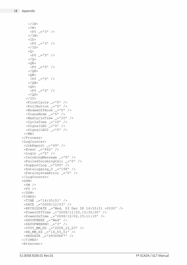
</IB> <IW> <P0 _="3" /> </IW> <ID> <P0 _="3" /> </ID> <Q> <P0 _="0" /> </Q> <QB> <P0 _="0" /> </QB> <QW> <P0 _="0" /> </QW> <QD> <P0 _="0" /> </QD> </IO> <FirstCycle _="0" /> <PollButton _="0" /> <ModemOffHook _="0" /> <TransMode _="0" /> <MaxCycleTime _="10" /> <CycleTime _="10" /> <SignalLED _="0" /> <SignalLED2 _="0" /> </MB> </Process> <LogCounter> <JobReport _="49" /> <Event _="842" /> <Login _="0" /> <IncomingMessage _="0" /> <FailedIncomingCall _="0" /> <SupportLog _="595" /> <Datalogging_0 _="198" /> <FatalSystemError _="0" /> </LogCounter> <GSM> <SM /> <FD /> </GSM> <TIMES> <TIME _="14:55:51" /> <DATE _="2008/12/03" /> <RFC822DATE _="Wed, 03 Dec 08 14:55:51 +0100" /> <PowerOffTime _="2008/11/20,13:30:00" /> <PowerOnTime _="2008/12/02,15:11:19" /> <DAYOFWEEK _="Wed" /> <DAYOFWEEKNO _="3" /> <YYYY_MM_DD _="2008_12_03" /> <HH_MM_SS _="14_55_51" /> <HEXDATE _="49369DF7" /> </TIMES> <Ethernet>
51.0058.9206.01 Rev.01 FP SCADA / GLT Manual
19 Appendix
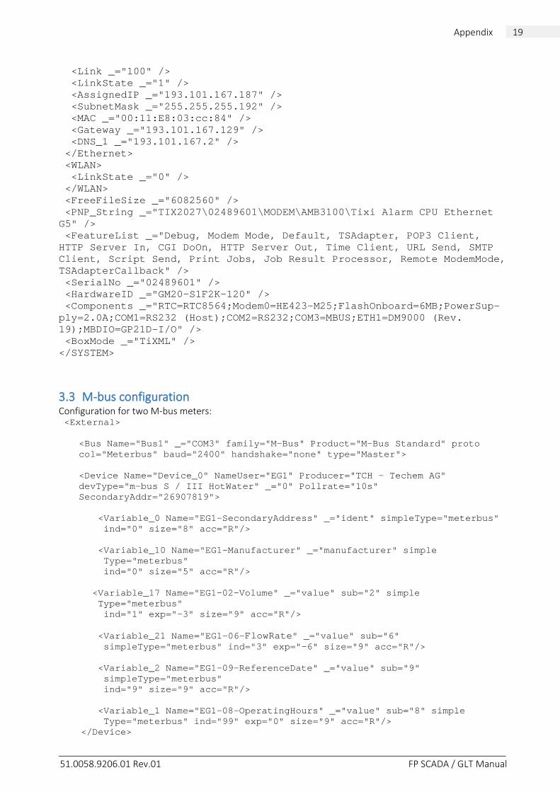
<Link _="100" /> <LinkState _="1" /> <AssignedIP _="193.101.167.187" /> <SubnetMask _="255.255.255.192" /> <MAC _="00:11:E8:03:cc:84" /> <Gateway _="193.101.167.129" /> <DNS_1 _="193.101.167.2" /> </Ethernet> <WLAN> <LinkState _="0" /> </WLAN> <FreeFileSize _="6082560" /> <PNP_String _="TIX2027\02489601\MODEM\AMB3100\Tixi Alarm CPU Ethernet G5" /> <FeatureList _="Debug, Modem Mode, Default, TSAdapter, POP3 Client, HTTP Server In, CGI DoOn, HTTP Server Out, Time Client, URL Send, SMTP Client, Script Send, Print Jobs, Job Result Processor, Remote ModemMode, TSAdapterCallback" /> <SerialNo _="02489601" /> <HardwareID _="GM20-S1F2K-120" /> <Components _="RTC=RTC8564;Modem0=HE423-M25;FlashOnboard=6MB;PowerSup-ply=2.0A;COM1=RS232 (Host);COM2=RS232;COM3=MBUS;ETH1=DM9000 (Rev. 19);MBDIO=GP21D-I/O" /> <BoxMode _="TiXML" /> </SYSTEM>
3.3 M-bus configuration Configuration for two M-bus meters: <External>
<Bus Name="Bus1" _="COM3" family="M-Bus" Product="M-Bus Standard" proto col="Meterbus" baud="2400" handshake="none" type="Master"> <Device Name="Device_0" NameUser="EG1" Producer="TCH - Techem AG" devType="m-bus S / III HotWater" _="0" Pollrate="10s" SecondaryAddr="26907819">
<Variable_0 Name="EG1-SecondaryAddress" _="ident" simpleType="meterbus" ind="0" size="8" acc="R"/> <Variable_10 Name="EG1-Manufacturer" _="manufacturer" simple Type="meterbus" ind="0" size="5" acc="R"/> <Variable_17 Name="EG1-02-Volume" _="value" sub="2" simple Type="meterbus" ind="1" exp="-3" size="9" acc="R"/> <Variable_21 Name="EG1-06-FlowRate" _="value" sub="6" simpleType="meterbus" ind="3" exp="-6" size="9" acc="R"/> <Variable_2 Name="EG1-09-ReferenceDate" _="value" sub="9" simpleType="meterbus" ind="9" size="9" acc="R"/> <Variable_1 Name="EG1-08-OperatingHours" _="value" sub="8" simple Type="meterbus" ind="99" exp="0" size="9" acc="R"/> </Device>
51.0058.9206.01 Rev.01 FP SCADA / GLT Manual
20 Appendix
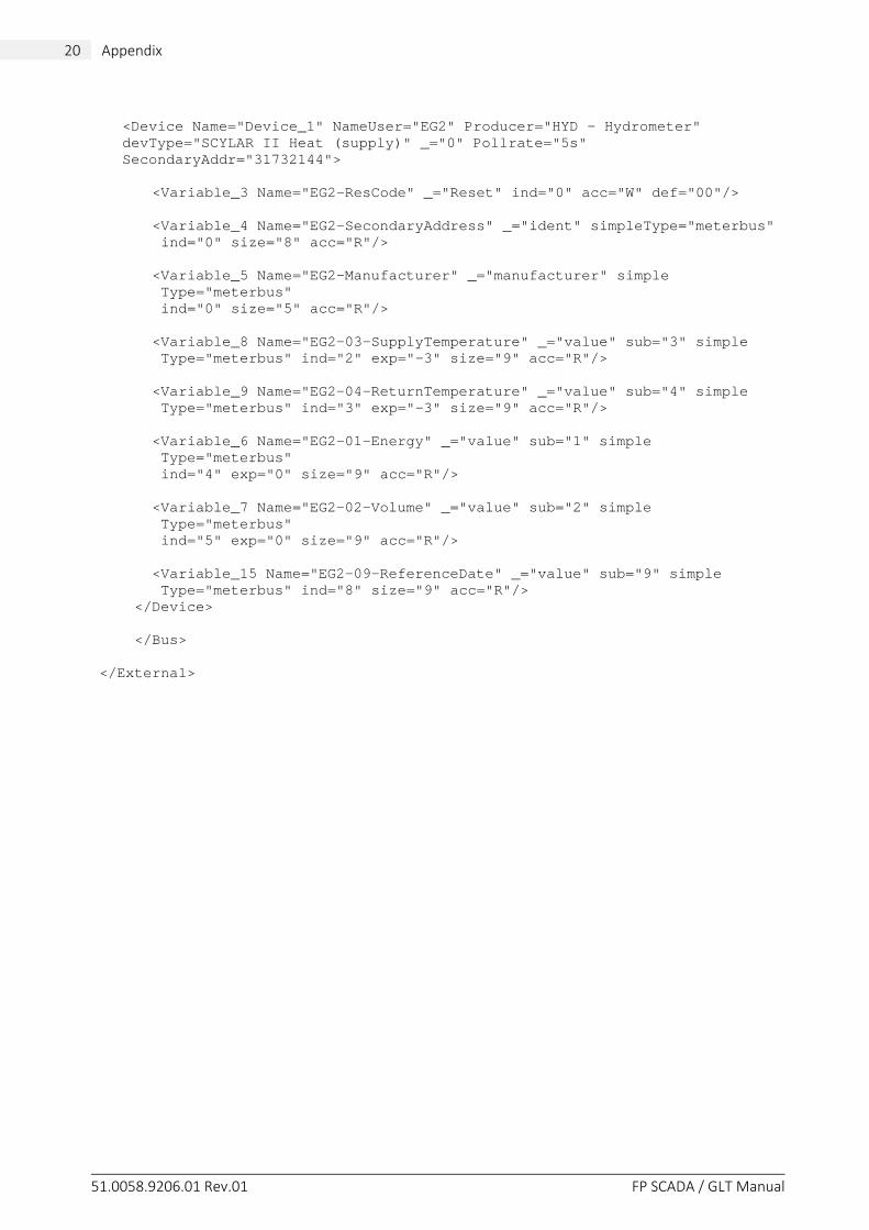
<Device Name="Device_1" NameUser="EG2" Producer="HYD - Hydrometer" devType="SCYLAR II Heat (supply)" _="0" Pollrate="5s" SecondaryAddr="31732144">
<Variable_3 Name="EG2-ResCode" _="Reset" ind="0" acc="W" def="00"/> <Variable_4 Name="EG2-SecondaryAddress" _="ident" simpleType="meterbus" ind="0" size="8" acc="R"/> <Variable_5 Name="EG2-Manufacturer" _="manufacturer" simple Type="meterbus" ind="0" size="5" acc="R"/> <Variable_8 Name="EG2-03-SupplyTemperature" _="value" sub="3" simple Type="meterbus" ind="2" exp="-3" size="9" acc="R"/> <Variable_9 Name="EG2-04-ReturnTemperature" _="value" sub="4" simple Type="meterbus" ind="3" exp="-3" size="9" acc="R"/> <Variable_6 Name="EG2-01-Energy" _="value" sub="1" simple Type="meterbus" ind="4" exp="0" size="9" acc="R"/> <Variable_7 Name="EG2-02-Volume" _="value" sub="2" simple Type="meterbus" ind="5" exp="0" size="9" acc="R"/> <Variable_15 Name="EG2-09-ReferenceDate" _="value" sub="9" simple Type="meterbus" ind="8" size="9" acc="R"/> </Device> </Bus> </External>