scada manual
DESCRIPTION
Scada programingTRANSCRIPT

MANUAL
60
SCADA SOFTWARE
User’s Manual
SCADA
59
Chapter1 Brief Introduction to FAB-SCADA Sytem....11.1 General Introduction..............................................11.2 Network Structure of FAB .....................................1
1.2.1 Network of 485 Buses......................................21.2.2 Network System of Super-Remote
Control by MODEM.........................................21.3 Brief Introduction to FAB-SCADA Sytem..............3
Chapter 2 Installation Of SCADA Sytem......................4
Chapter 3 Operation Instructions and Quick Buttons..83.1 Instructions and Buttons in the Control Interface...8
3.1.1 System (Operation Instructions for System Management)................................8
3.1.2 Mronitor(Operation Instructionfor Monitor Setup)............................................8
3.1.3 User (User Management Instructions).............93.1.4 Query (Query instructions of the System)........93.1.5 Report............................................................103.1.6 Tools..............................................................103.1.7 Help...............................................................10
3.2 Operation Instructions and Quick Buttons in Drawing Interface............................................11
3.2.1 File (Files management)................................113.2.2 Edit ................................................................113.2.3 Tools..............................................................123.2.4 Help...............................................................12
Chapter 4 Build a Supervisor Control System...........134.1 Station design......................................................134.2 Add/Delete FAB...................................................154.3 Defi ne the FAB I/O Port ......................................17
Contents
4.4 Drawing Monitoring Interface..............................234.4.1 Operation Instruments In Drawing Interface..234.4.2 Drawing Tools................................................244.4.3 Drawing the Monitoring Diagram....................26
4.4.3.1 Page Setting............................................264.4.3.2 Draw the Monitor Diagram.......................274.4.3.3 Analyze the Communicating State...........38
Chapter 5 User Management....................................395.1 Modify Manager Name........................................395.2 User Manage.......................................................39
5.2.1 Append..........................................................405.2.2 Delete............................................................405.2.3 Modify Password...........................................405.2.4 Query the User Information............................41
5.3 User Login...........................................................415.4 User Logout Logout............................................425.5 Explanations for User Authorities.........................42
Chapter 6 System Confi guration................................436.1 Set FAB Time ......................................................436.2 Print.....................................................................436.3 Deploy................................................................44
Chapter 7 Data Query................................................467.1 Data Query..........................................................467.2 Back-up the Data Base.......................................48
Chapter 8 Report.......................................................508.1 Create Report......................................................508.2 Browse............................................................... 55
FAB SCADA FAB SCADA
SCADA
1
CHAPTER 1 Brief Introduction to FAB-SCADA System
1.1 General IntroductionSCADA System is the System for Supervisor Control and Data Acquisition. It can collect digital and
analog of the fi elds, carry out live or remote real-time control over the fi elds controlled by the FABs and provide with necessary resource management function.
FAB-SCADA System Software is an easily operated, widely used industrial software for the realization of network function of the FAB Intelligent Controller. It uses FAB as the terminal control unit and it is a network system that collectively carries out the real-time data acquisition and supervisor control over the FABs that separately carry out the auto-control task. On the basis of the FAB-SCADA System Software, users can build complete supervisor management system from PCs to FABS of the control according to the specifi c fi eld environments and requirements.
Except the basic functions of common PLC, FAB has some special functions: real-time clock function, input and transmission of the analog, voice function, network and remote supervisor control function and so on. In this manual we will introduce how to use the network of FAB Intelligent Controllers to drive FAB-SCADA System.
1.2 Network Structure of FAB There are several methods of supervisor control system to use FAB as the site-control unit. Users may
build the following three supervisor control systems according to different control requirements.
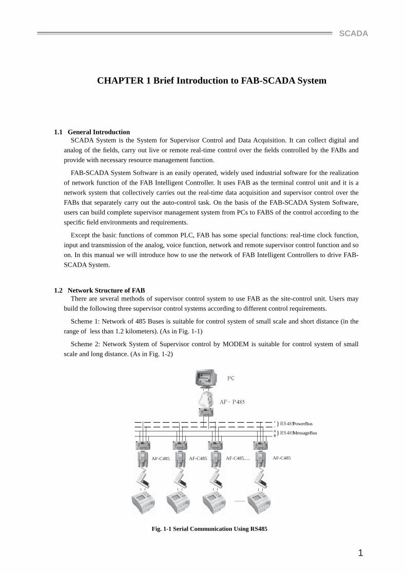
Scheme 1: Network of 485 Buses is suitable for control system of small scale and short distance (in the range of less than 1.2 kilometers). (As in Fig. 1-1)
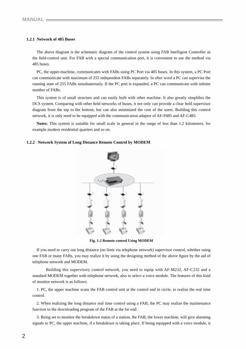
Scheme 2: Network System of Supervisor control by MODEM is suitable for control system of small scale and long distance. (As in Fig. 1-2)
Fig. 1-1 Serial Communication Using RS485
}RS485MessageBusAB
+_
AF-P485
PC
}RS485PowerBus
AF-C485AF-C485.....AF-C485AF-C485
.........
MANUAL
2
1.2.1 Network of 485 Buses
The above diagram is the schematic diagram of the control system using FAB Intelligent Controller as the fi eld-control unit. For FAB wirh a special communication port, it is convenient to use the method via 485 buses.
PC, the upper-machine, communicates with FABs using PC Port via 485 buses. In this system, a PC Port can communicate with maximum of 255 independent FABs separately. In ofter word a PC can supervise the running state of 255 FABs simultaneously. If the PC port is expanded, a PC can communicate with infi nite number of FABs.
This system is of small structure and can easily built with other machine. It also greatly simplifi es the DCS system. Comparing with other fi eld networks of buses, it not only can provide a clear fi eld supervisor diagram from the top to the bottom, but can also minimized the cost of the users. Building this control network, it is only need to be equipped with the communication adaptor of AF-P485 and AF-C485.
Notes: This system is suitable for small scale in general in the range of less than 1.2 kilometers, for example modern residential quarters and so on.
1.2.2 Network System of Long Distance Remote Control by MODEM
Fig. 1-2 Remote control Using MODEM
If you need to carry out long distance (no limit via telephone network) supervisor control, whether using one FAB or many FABs, you may realize it by using the designing method of the above fi gure by the aid of telephone network and MODEM.
Building this supervisory control network, you need to equip with AF-M232, AF-C232 and a standard MODEM together with telephone network, also to select a voice module. The features of this kind of monitor network is as follows:
1. PC, the upper machine scans the FAB control unit at the control end in circle, to realize the real time control.
2. When realizing the long distance real time control using a FAB, the PC may realize the maintenance function to the downloading program of the FAB at the far end.
3. Being set to monitor the breakdown status of a station, the FAB, the lower machine, will give alarming signals to PC, the upper machine, if a breakdown is taking place. If being equipped with a voice module, it
SCADA
3
will send voice alarming signals and dial the pre-set telephone number to alarm.
1.3 Brief Introduction to FAB-SCADA System
FAB-SCADA System provides the users with a friendly secondary development interface and makes it possible for the users to build a control system as they need. It may be the collective control of intelligent residential quarters or of PCs dispersed in cities.
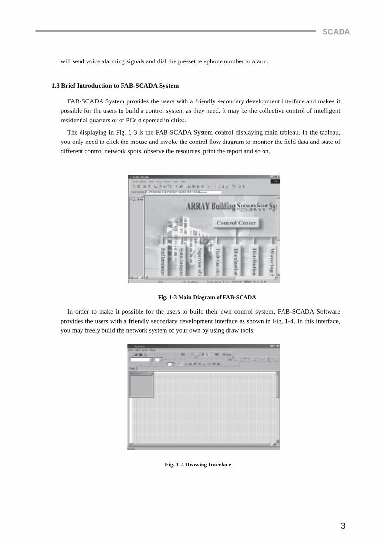
The displaying in Fig. 1-3 is the FAB-SCADA System control displaying main tableau. In the tableau, you only need to click the mouse and invoke the control fl ow diagram to monitor the fi eld data and state of different control network spots, observe the resources, print the report and so on.
Fig. 1-3 Main Diagram of FAB-SCADA
In order to make it possible for the users to build their own control system, FAB-SCADA Software provides the users with a friendly secondary development interface as shown in Fig. 1-4. In this interface, you may freely build the network system of your own by using draw tools.
Fig. 1-4 Drawing Interface
MANUAL
4
Chapter 2 Installation of SCADA System
SCADA System can be used in the environment of WIN9X/WINNT/WIN2000 and so on and the hardware requirements are above 586.
Detailed installation steps are as follows:
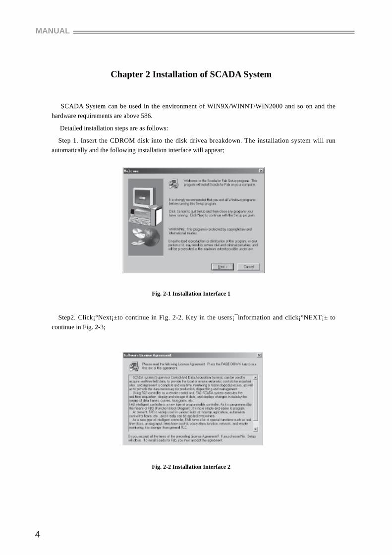
Step 1. Insert the CDROM disk into the disk drivea breakdown. The installation system will run automatically and the following installation interface will appear;
Fig. 2-1 Installation Interface 1
Step2. Click¡°Next¡±to continue in Fig. 2-2. Key in the users¡¯information and click¡°NEXT¡± to continue in Fig. 2-3;
Fig. 2-2 Installation Interface 2
SCADA
5
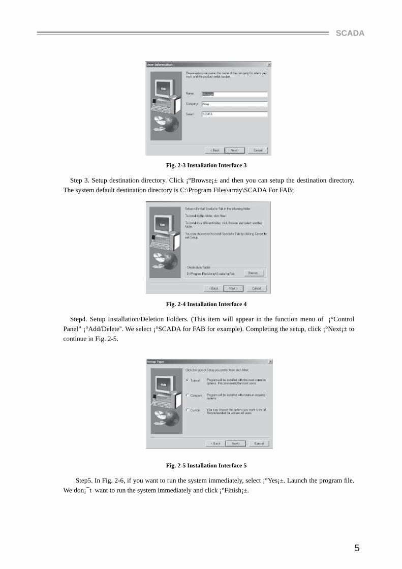
Fig. 2-3 Installation Interface 3
Step 3. Setup destination directory. Click ¡°Browse¡± and then you can setup the destination directory. The system default destination directory is C:\Program Files\array\SCADA For FAB;
Fig. 2-4 Installation Interface 4
Step4. Setup Installation/Deletion Folders. (This item will appear in the function menu of ¡°Control Panel” ¡°Add/Delete”. We select ¡°SCADA for FAB for example). Completing the setup, click ¡°Next¡± to continue in Fig. 2-5.
Fig. 2-5 Installation Interface 5
Step5. In Fig. 2-6, if you want to run the system immediately, select ¡°Yes¡±. Launch the program fi le. We don¡¯t want to run the system immediately and click ¡°Finish¡±.
MANUAL
6
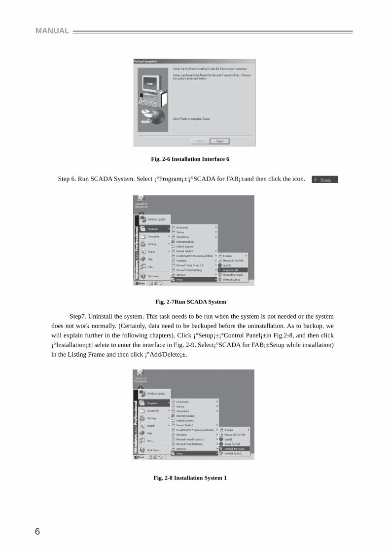
Fig. 2-6 Installation Interface 6
Step 6. Run SCADA System. Select ¡°Program¡±|¡°SCADA for FAB¡±and then click the icon.
Fig. 2-7Run SCADA System
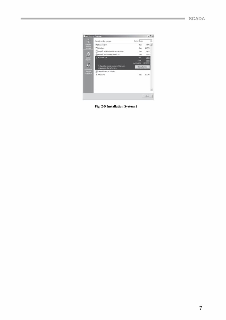
Step7. Uninstall the system. This task needs to be run when the system is not needed or the system does not work normally. (Certainly, data need to be backuped before the uninstallation. As to backup, we will explain further in the following chapters). Click ¡°Setup¡±¡°Control Panel¡±in Fig.2-8, and then click ¡°Installation¡±| selete to enter the interface in Fig. 2-9. Select¡°SCADA for FAB¡±Setup while installation) in the Listing Frame and then click ¡°Add/Delete¡±.
Fig. 2-8 Installation System 1
SCADA
7
Fig. 2-9 Installation System 2
MANUAL
8
Chapter 3 Operation Instructions and Quick Buttons
3.1 Instructions and Buttons in the Control Interface
In the instruction toolbar of FAB-SCADA system running state there are some main operation instructions such as System, Monitor, User, Query, Report, Tools and Help. They are used to complete the system equipping and to observe the values. We will introduce their functions one by one in the following.
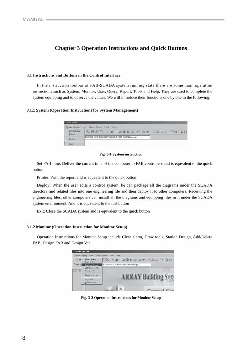
3.1.1 System (Operation Instructions for System Management)
Fig. 3-1 System instruction
Set FAB time: Deliver the current time of the computer to FAB controllers and is equvalent to the quick button
Printer: Print the report and is equvalent to the quick button
Deploy: When the user edits a control system, he can package all the diagrams under the SCADA directory and related fi les into one engineering fi le and then deploy it to other computers. Receiving the engineering fi les, other computers can install all the diagrams and equipping fi les in it under the SCADA system environment. And it is equvalent to the fast button
Exit: Close the SCADA system and is equvalent to the quick button
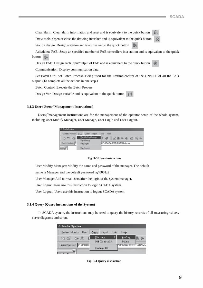
3.1.2 Monitor (Operation Instruction for Monitor Setup)
Operation Instructions for Monitor Setup include Clear alarm, Draw tools, Station Design, Add/Delete FAB, Design FAB and Design Var.
Fig. 3-2 Operation Instructions for Monitor Setup
SCADA
9
Clear alarm: Clear alarm information and reset and is equivalent to the quick button
Draw tools: Open or close the drawing interface and is equivalent to the quick button
Station design: Design a station and is equivalent to the quick button
Add/delete FAB: Setup an specifi ed number of FAB controllers in a station and is equivalent to the quick button
Design FAB: Design each input/output of FAB and is equivalent to the quick button
Communication: Display communication data.
Set Batch Ctrl: Set Batch Process. Being used for the lifetime-control of the ON/OFF of all the FAB output. (To complete all the actions in one step.)
Batch Control: Execute the Batch Process.
Design Var: Design variable and is equivalent to the quick button
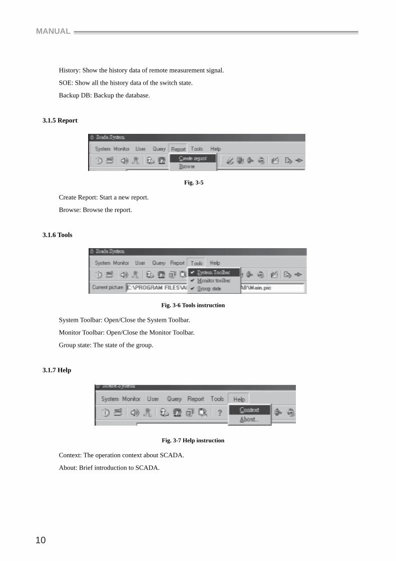
3.1.3 User (Users¡¯Management Instructions)
Users¡¯management instructions are for the management of the operator setup of the whole system, including User Modify Manager, User Manage, User Login and User Logout.
Fig. 3-3 Users instruction
User Modify Manager: Modify the name and password of the manager. The default
name is Manager and the default password is¡°0001¡±
User Manage: Add normal users after the login of the system manager.
User Login: Users use this instruction to login SCADA system.
User Logout: Users use this instruction to logout SCADA system.
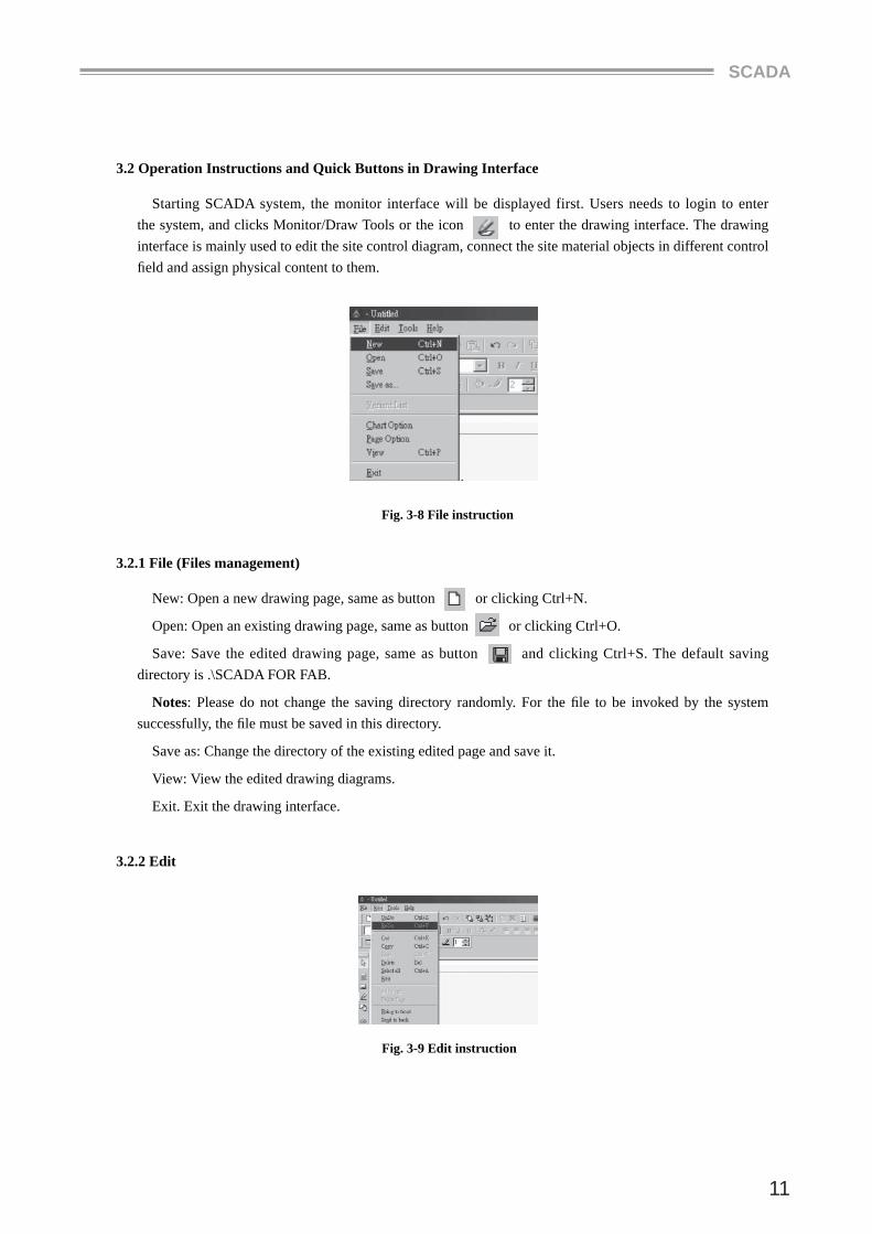
3.1.4 Query (Query instructions of the System)
In SCADA system, the instructions may be used to query the history records of all measuring values, curve diagrams and so on.
Fig. 3-4 Query instruction
MANUAL
10
History: Show the history data of remote measurement signal.
SOE: Show all the history data of the switch state.
Backup DB: Backup the database.
3.1.5 Report
Fig. 3-5
Create Report: Start a new report.
Browse: Browse the report.
3.1.6 Tools
Fig. 3-6 Tools instruction
System Toolbar: Open/Close the System Toolbar.
Monitor Toolbar: Open/Close the Monitor Toolbar.
Group state: The state of the group.
3.1.7 Help
Fig. 3-7 Help instruction
Context: The operation context about SCADA.
About: Brief introduction to SCADA.
SCADA
11
3.2 Operation Instructions and Quick Buttons in Drawing Interface
Starting SCADA system, the monitor interface will be displayed first. Users needs to login to enter the system, and clicks Monitor/Draw Tools or the icon to enter the drawing interface. The drawing interface is mainly used to edit the site control diagram, connect the site material objects in different control fi eld and assign physical content to them.
Fig. 3-8 File instruction
3.2.1 File (Files management)
New: Open a new drawing page, same as button or clicking Ctrl+N.
Open: Open an existing drawing page, same as button or clicking Ctrl+O.
Save: Save the edited drawing page, same as button and clicking Ctrl+S. The default saving directory is .\SCADA FOR FAB.
Notes: Please do not change the saving directory randomly. For the fi le to be invoked by the system successfully, the fi le must be saved in this directory.
Save as: Change the directory of the existing edited page and save it.
View: View the edited drawing diagrams.
Exit. Exit the drawing interface.
3.2.2 Edit
Fig. 3-9 Edit instruction
MANUAL
12
Undo: Undo the editing contents of the pre-step.
Redo: Clear the undo.
Cut: Cut the selected contents.
Copy: Copy the selected contents.
Paste: Paste the copied or cut contents.
Delete: Delete the selected contents.
Select all: Select the contents of the whole page.
Bring to front: Move to the upper layer.
Send to back: Move to the lower layer.
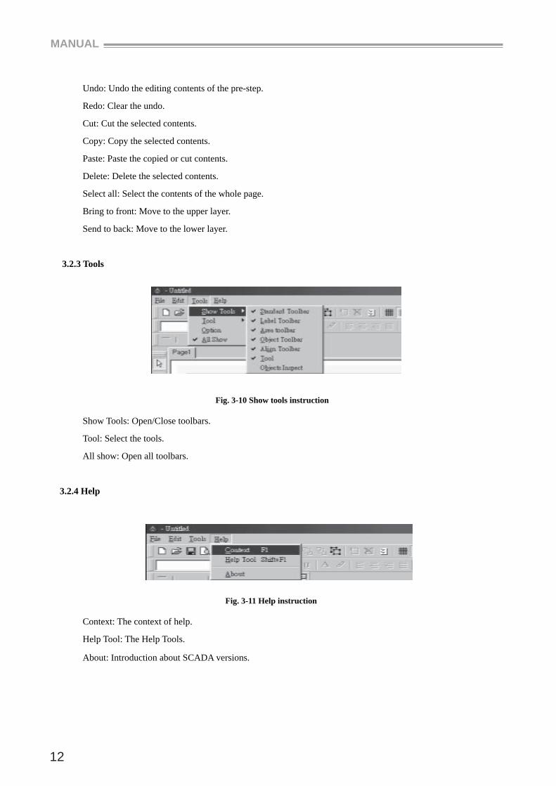
3.2.3 Tools
Fig. 3-10 Show tools instruction
Show Tools: Open/Close toolbars.
Tool: Select the tools.
All show: Open all toolbars.
3.2.4 Help
Fig. 3-11 Help instruction
Context: The context of help.
Help Tool: The Help Tools.
About: Introduction about SCADA versions.
SCADA
13
Chapter 4 Build a Supervisory Control System
In previous chapters we introduce the FAB-SCADA System Software which is an industrial software using FAB intelligent controllers as the fi eld control unit. On the basis of FAB-SCADA system software, users may build a supervisory control system from PC to FAB according to specifi c fi eld environment and control requirements.
To build a complete control system, a station has to be designed fi rst, then necessary FAB intelligent controllers will be setup. Then control input/output signals relevant to each input/output port and relevant fi eld fl ow diagram will be setup. Corresponding the system diagram to the fi eld control port one by one, thus the system control can be realized. In order to realize the above procedures, FAB-SCADA software provides with relevant operation instructions, which will be introduced in detail in the following.
For example, we need to build a control system over residential quarters. It has 100 households, each of them needs a FAB intelligent controller. Each household uses a FAB as the fi eld controller for the theft monitor, gas leakage monitor, room illumination monitor, air-conditioner control, exhaust fan, door and etc. In the central control room, a PC is setup for real-time control of all the FABs and the state of all the households. If there is monitored situation happening in a household, FAB will alarm automatically and send the recorded emergency call to any pre-set telephone number.
We can select the networking methods of Scheme 1, communicating via 485 buses, to complete real time control in this example.
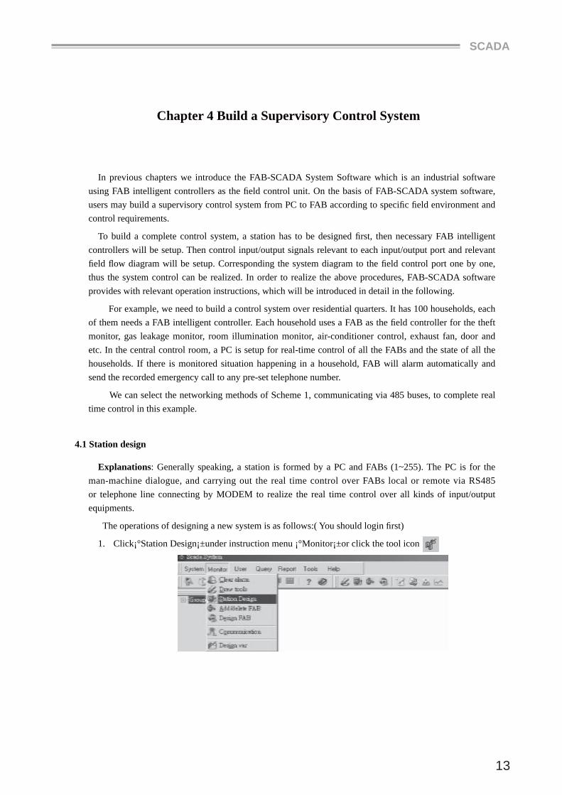
4.1 Station design
Explanations: Generally speaking, a station is formed by a PC and FABs (1~255). The PC is for the man-machine dialogue, and carrying out the real time control over FABs local or remote via RS485 or telephone line connecting by MODEM to realize the real time control over all kinds of input/output equipments.
The operations of designing a new system is as follows:( You should login fi rst)
1. Click¡°Station Design¡±under instruction menu ¡°Monitor¡±or click the tool icon
MANUAL
14
Fig. 4-1 Monitor Instruction Menu
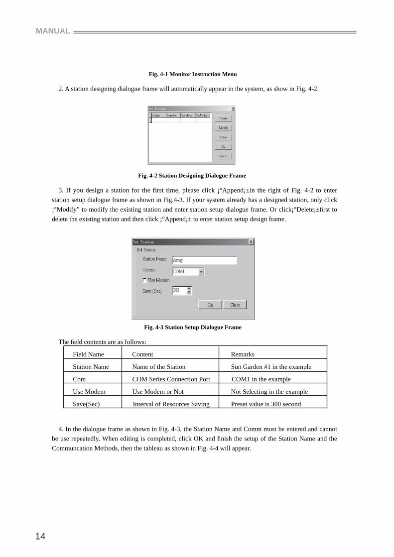
2. A station designing dialogue frame will automatically appear in the system, as show in Fig. 4-2.
Fig. 4-2 Station Designing Dialogue Frame
3. If you design a station for the first time, please click ¡°Append¡±in the right of Fig. 4-2 to enter station setup dialogue frame as shown in Fig.4-3. If your system already has a designed station, only click ¡°Modify” to modify the existing station and enter station setup dialogue frame. Or click¡°Delete¡±fi rst to delete the existing station and then click ¡°Append¡± to enter station setup design frame.
Fig. 4-3 Station Setup Dialogue Frame
The fi eld contents are as follows:
Field Name Content Remarks
Station Name Name of the Station Sun Garden #1 in the example
Com COM Series Connection Port COM1 in the example
Use Modem Use Modem or Not Not Selecting in the example
Save(Sec) Interval of Resources Saving Preset value is 300 second
4. In the dialogue frame as shown in Fig. 4-3, the Station Name and Comm must be entered and cannot be use repeatedly. When editing is completed, click OK and fi nish the setup of the Station Name and the Communcation Methods, then the tableau as shown in Fig. 4-4 will appear.
SCADA
15
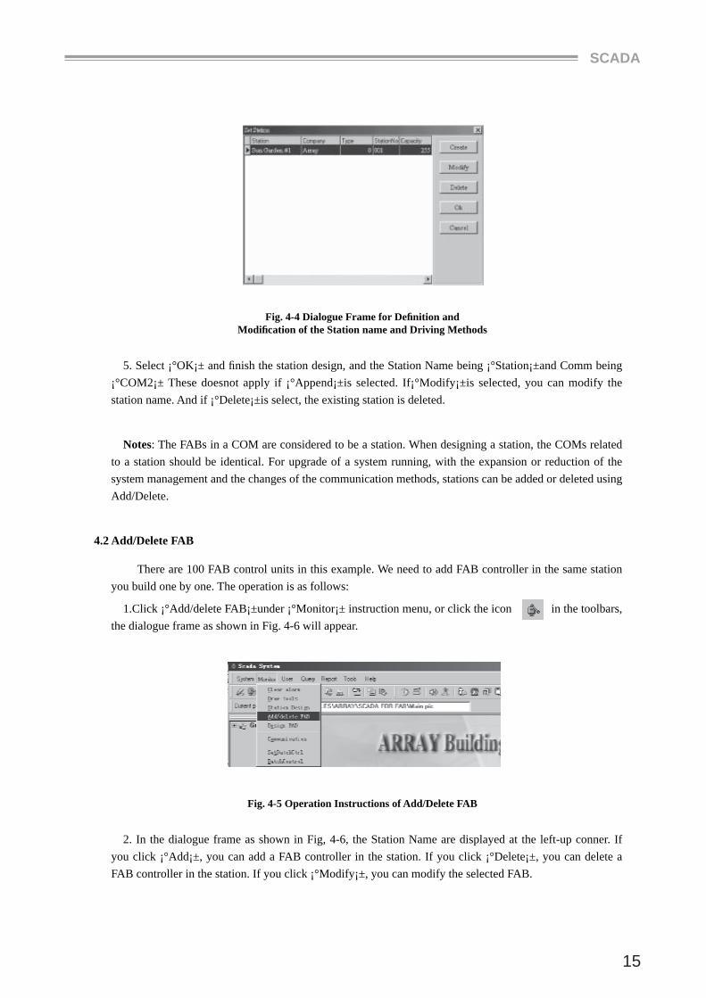
Fig. 4-4 Dialogue Frame for Defi nition and Modifi cation of the Station name and Driving Methods
5. Select ¡°OK¡± and fi nish the station design, and the Station Name being ¡°Station¡±and Comm being ¡°COM2¡± These doesnot apply if ¡°Append¡±is selected. If¡°Modify¡±is selected, you can modify the station name. And if ¡°Delete¡±is select, the existing station is deleted.
Notes: The FABs in a COM are considered to be a station. When designing a station, the COMs related to a station should be identical. For upgrade of a system running, with the expansion or reduction of the system management and the changes of the communication methods, stations can be added or deleted using Add/Delete.
4.2 Add/Delete FAB
There are 100 FAB control units in this example. We need to add FAB controller in the same station you build one by one. The operation is as follows:
1.Click ¡°Add/delete FAB¡±under ¡°Monitor¡± instruction menu, or click the icon in the toolbars, the dialogue frame as shown in Fig. 4-6 will appear.
Fig. 4-5 Operation Instructions of Add/Delete FAB
2. In the dialogue frame as shown in Fig, 4-6, the Station Name are displayed at the left-up conner. If you click ¡°Add¡±, you can add a FAB controller in the station. If you click ¡°Delete¡±, you can delete a FAB controller in the station. If you click ¡°Modify¡±, you can modify the selected FAB.
MANUAL
16
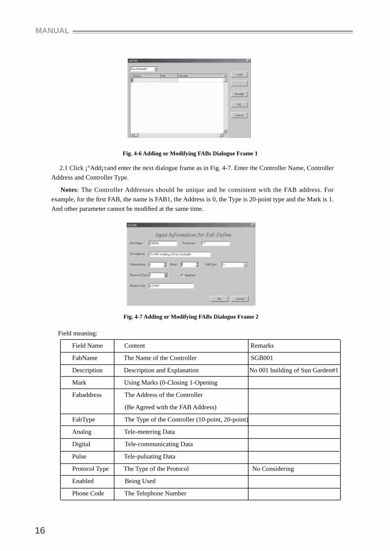
Fig. 4-6 Adding or Modifying FABs Dialogue Frame 1
2.1 Click ¡°Add¡±and enter the next dialogue frame as in Fig. 4-7. Enter the Controller Name, Controller Address and Controller Type.
Notes: The Controller Addresses should be unique and be consistent with the FAB address. For example, for the fi rst FAB, the name is FAB1, the Address is 0, the Type is 20-point type and the Mark is 1. And other parameter cannot be modifi ed at the same time.
Fig. 4-7 Adding or Modifying FABs Dialogue Frame 2
Field meaning:
Field Name Content Remarks
FabName The Name of the Controller SGB001
Description Description and Explanation No 001 building of Sun Garden#1
Mark Using Marks (0-Closing 1-Opening
Fabaddress The Address of the Controller
(Be Agreed with the FAB Address)
FabType The Type of the Controller (10-point, 20-point)
Analog Tele-metering Data
Digital Tele-communicating Data
Pulse Tele-pulsating Data
Protocol Type The Type of the Protocol No Considering
Enabled Being Used
Phone Code The Telephone Number
SCADA
17
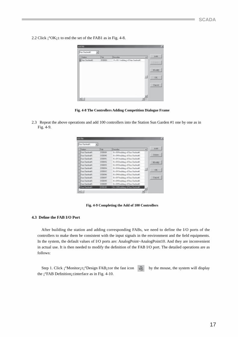
2.2 Click ¡°OK¡± to end the set of the FAB1 as in Fig. 4-8.
Fig. 4-8 The Controllers Adding Competition Dialogue Frame
2.3 Repeat the above operations and add 100 controllers into the Station Sun Garden #1 one by one as in Fig. 4-9.
Fig. 4-9 Completing the Add of 100 Controllers
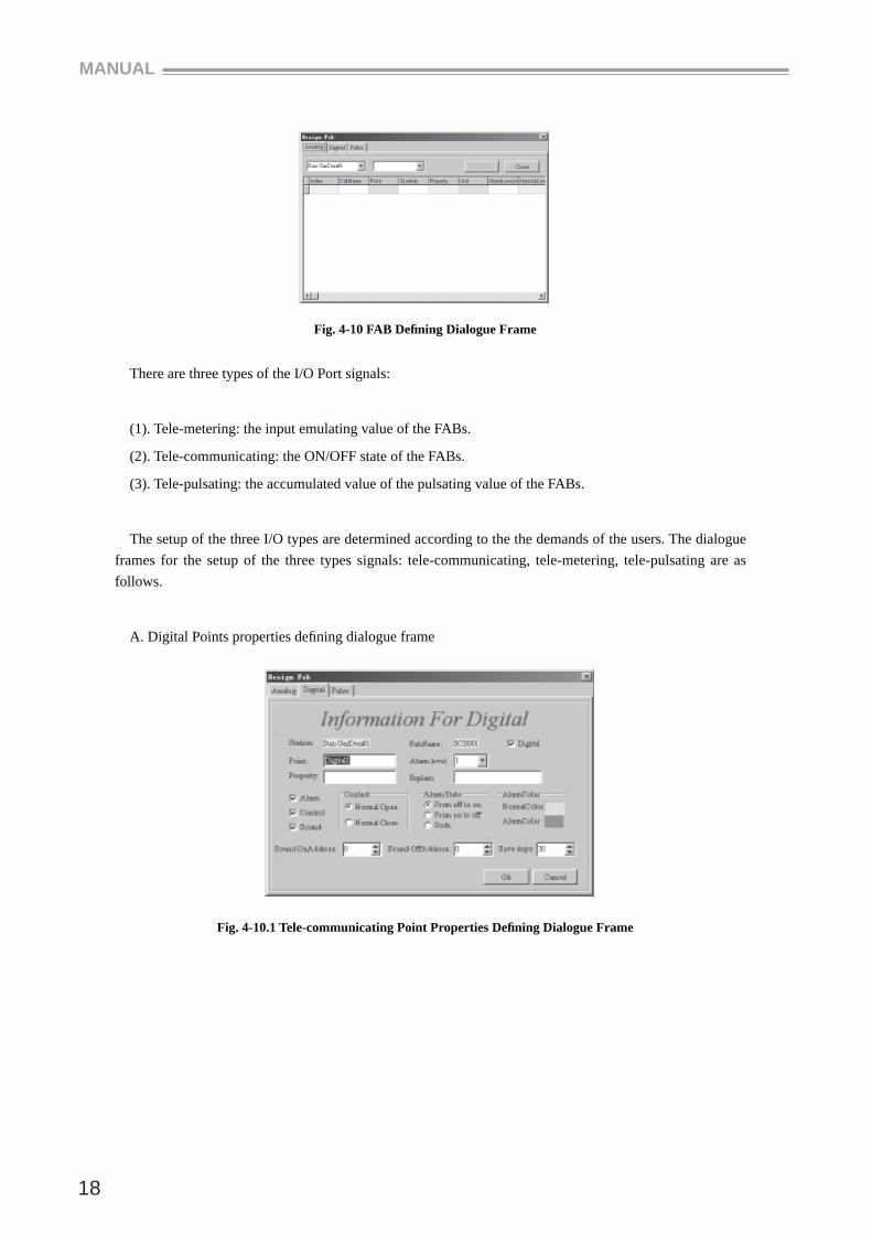
4.3 Defi ne the FAB I/O Port
After building the station and adding corresponding FABs, we need to define the I/O ports of the controllers to make them be consistent with the input signals in the environment and the fi eld equipments. In the system, the default values of I/O ports are: AnalogPoint~AnalogPoint10. And they are inconvenient in actual use. It is then needed to modify the defi nition of the FAB I/O port. The detailed operations are as follows:
Step 1. Click ¡°Monitor¡±¡°Design FAB¡±or the fast icon by the mouse, the system will display the ¡°FAB Defi nition¡±interface as in Fig. 4-10.
MANUAL
18
Fig. 4-10 FAB Defi ning Dialogue Frame
There are three types of the I/O Port signals:
(1). Tele-metering: the input emulating value of the FABs.
(2). Tele-communicating: the ON/OFF state of the FABs.
(3). Tele-pulsating: the accumulated value of the pulsating value of the FABs.
The setup of the three I/O types are determined according to the the demands of the users. The dialogue frames for the setup of the three types signals: tele-communicating, tele-metering, tele-pulsating are as follows.
A. Digital Points properties defi ning dialogue frame
Fig. 4-10.1 Tele-communicating Point Properties Defi ning Dialogue Frame
SCADA
19
The content of each rail are as follows:
Rail Name Content Remarks
Point Defi ning the I/O Port
Alarm Level The Level of the Alarm
Property Property
Explain Explanation
Alarm Alarm or Not Not
Control Controllable or Not
Sound Sound Alarm or Not
Normal Open Always Being Open Select one of them
Normal Close Always Being Closed
From off to on From Closed to Open Select one of them
From on to off From Open to Closed
Both Select the Both States
Normal Color The Normal Color
Alarm Color The Alarming Color
Explanations:
(1). Alarming Level: the alarming system can be set into 6 levels. Level 1 is the highest level. The alarming level for each port can be set according to the urgency of the alarm.
(2). Controllable or Not Controllable: If the port is set to be controllable, then the PC can control its ON/OFF directly.
(3). Sound Alarm Enable and Disable: The alarming message is pre-recorded. And the addressed of the alarming message are set by ¡°Sound On Address¡± and ¡°Sound Off Address¡±
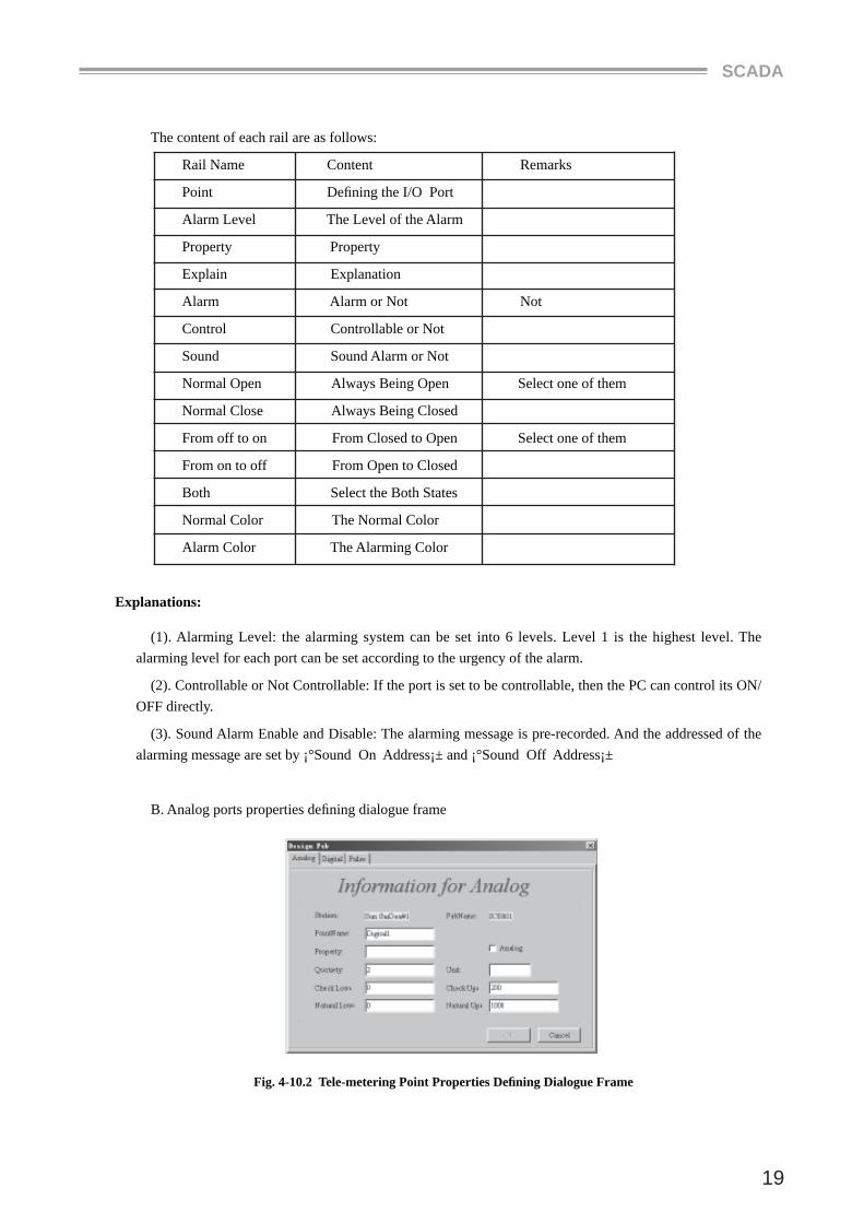
B. Analog ports properties defi ning dialogue frame
Fig. 4-10.2 Tele-metering Point Properties Defi ning Dialogue Frame
MANUAL
20
The meanings of each rail are as follows:
Rail Name Content Remarks
Point Defi ning the I/O Port
Sum Accumulating the Input
fSimulation Setting as tele-metering
Property Property
Quotiety Proportion coeffi cient
Unit Unit
Check low The Lowest Limit
Check up The Uppest Limit
Natural low The Lower Limit
Natural up The Upper Limit
C. Pulse ports properties defi ning dialogue frame
The tele-pulsating ports properties defining dialogue frame is the same as the tele-metering ports properties defi ning dialogue frame.
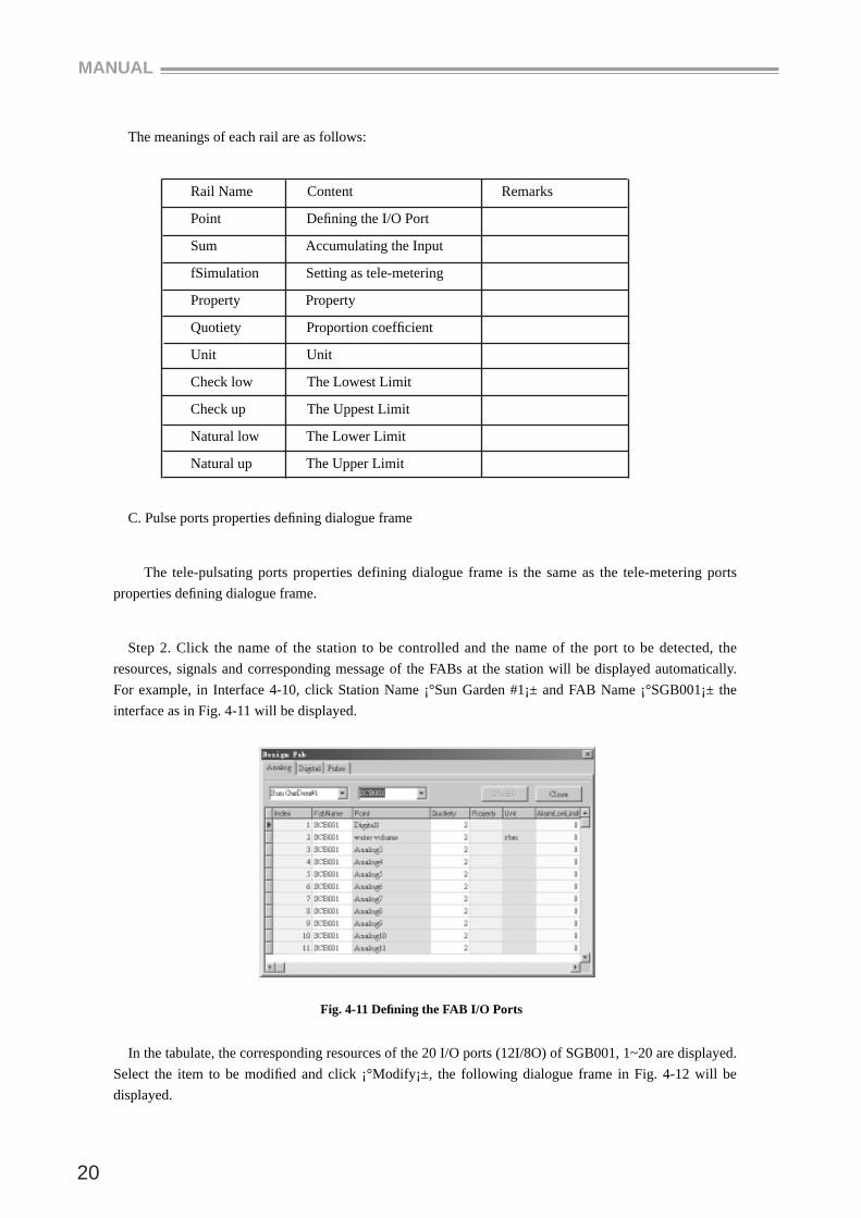
Step 2. Click the name of the station to be controlled and the name of the port to be detected, the resources, signals and corresponding message of the FABs at the station will be displayed automatically. For example, in Interface 4-10, click Station Name ¡°Sun Garden #1¡± and FAB Name ¡°SGB001¡± the interface as in Fig. 4-11 will be displayed.
Fig. 4-11 Defi ning the FAB I/O Ports
In the tabulate, the corresponding resources of the 20 I/O ports (12I/8O) of SGB001, 1~20 are displayed. Select the item to be modifi ed and click ¡°Modify¡±, the following dialogue frame in Fig. 4-12 will be displayed.
SCADA
21
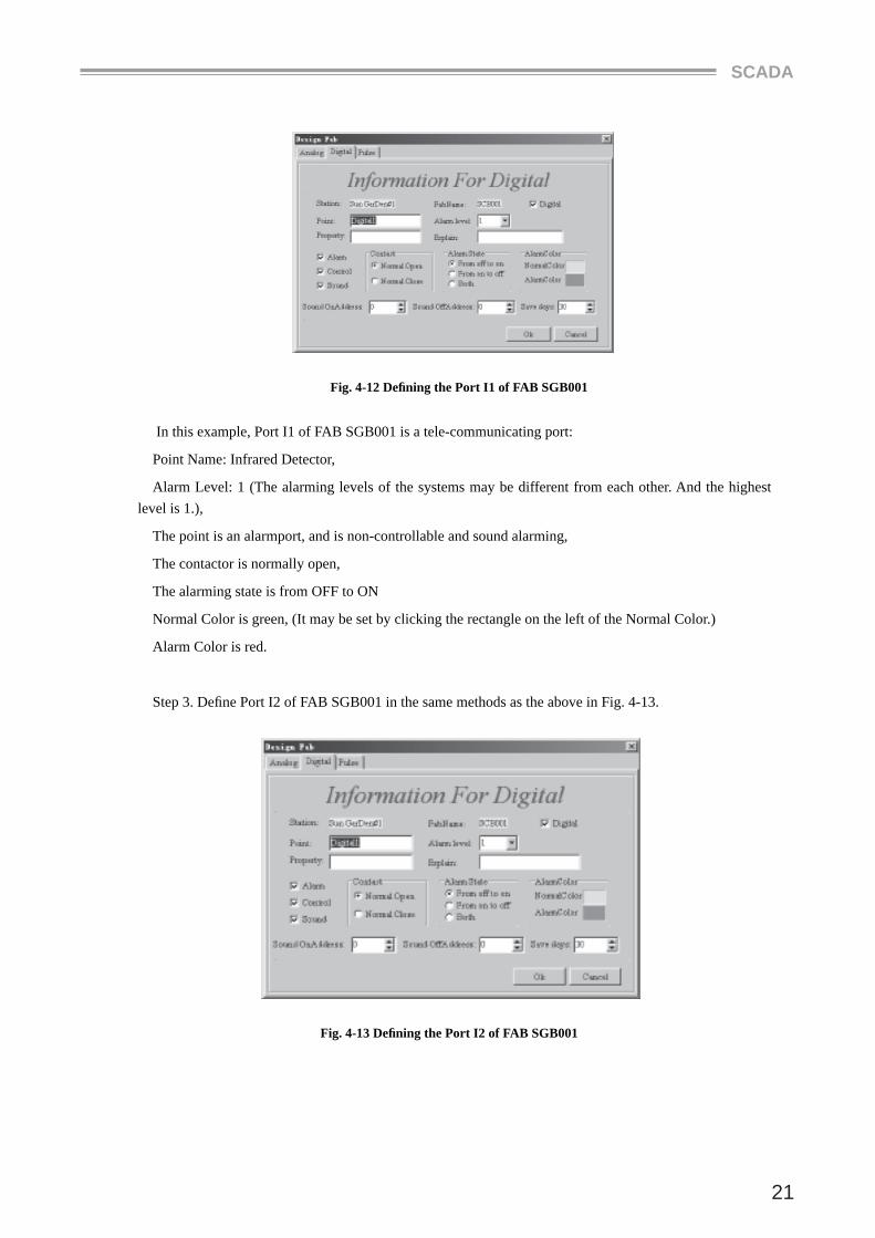
Fig. 4-12 Defi ning the Port I1 of FAB SGB001
In this example, Port I1 of FAB SGB001 is a tele-communicating port:
Point Name: Infrared Detector,
Alarm Level: 1 (The alarming levels of the systems may be different from each other. And the highest level is 1.),
The point is an alarmport, and is non-controllable and sound alarming,
The contactor is normally open,
The alarming state is from OFF to ON
Normal Color is green, (It may be set by clicking the rectangle on the left of the Normal Color.)
Alarm Color is red.
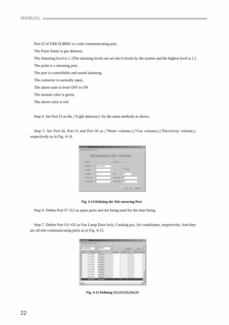
Step 3. Defi ne Port I2 of FAB SGB001 in the same methods as the above in Fig. 4-13.
Fig. 4-13 Defi ning the Port I2 of FAB SGB001
MANUAL
22
Port I2 of FAB SGB001 is a tele-communicating port,
The Point Name is gas detector,
The Alarming level is 1. (The alarming levels are set into 6 levels by the system and the highest level is 1.)
The point is a alarming port,
The port is controllable and sound alarming.
The contactor is normally open,
The alarm state is from OFF to ON
The normal color is green,
The alarm color is red.
Step 4. Set Port I3 as the ¡°Light detector¡± by the same methods as above.
Step 5. Set Port I4, Port I5 and Port I6 as ¡°Water volume¡±¡°Gas volume¡±¡°Electricity volume¡± respectively as in Fig. 4-14.
Fig. 4-14 Defi ning the Tele-metering Port
Step 6. Defi ne Port I7~I12 as spare ports and not being used for the time being.
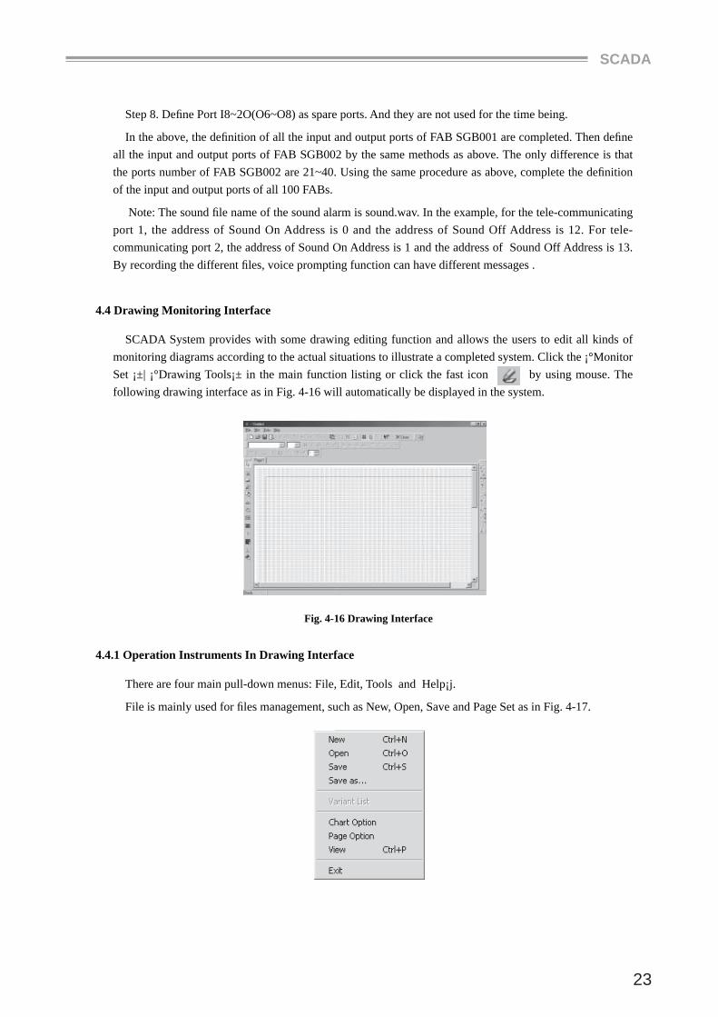
Step 7. Defi ne Port O1~O5 as Fan Lamp Door lock, Cooking pot, Air conditioner, respectively. And they are all tele-communicating ports as in Fig. 4-15.
Fig. 4-15 Defi ning O1,O2,O3,O4,O5
SCADA
23
Step 8. Defi ne Port I8~2O(O6~O8) as spare ports. And they are not used for the time being.
In the above, the defi nition of all the input and output ports of FAB SGB001 are completed. Then defi ne all the input and output ports of FAB SGB002 by the same methods as above. The only difference is that the ports number of FAB SGB002 are 21~40. Using the same procedure as above, complete the defi nition of the input and output ports of all 100 FABs.
Note: The sound fi le name of the sound alarm is sound.wav. In the example, for the tele-communicating port 1, the address of Sound On Address is 0 and the address of Sound Off Address is 12. For tele-communicating port 2, the address of Sound On Address is 1 and the address of Sound Off Address is 13. By recording the different fi les, voice prompting function can have different messages .
4.4 Drawing Monitoring Interface
SCADA System provides with some drawing editing function and allows the users to edit all kinds of monitoring diagrams according to the actual situations to illustrate a completed system. Click the ¡°Monitor Set ¡±| ¡°Drawing Tools¡± in the main function listing or click the fast icon by using mouse. The following drawing interface as in Fig. 4-16 will automatically be displayed in the system.
Fig. 4-16 Drawing Interface
4.4.1 Operation Instruments In Drawing Interface
There are four main pull-down menus: File, Edit, Tools and Help¡j.
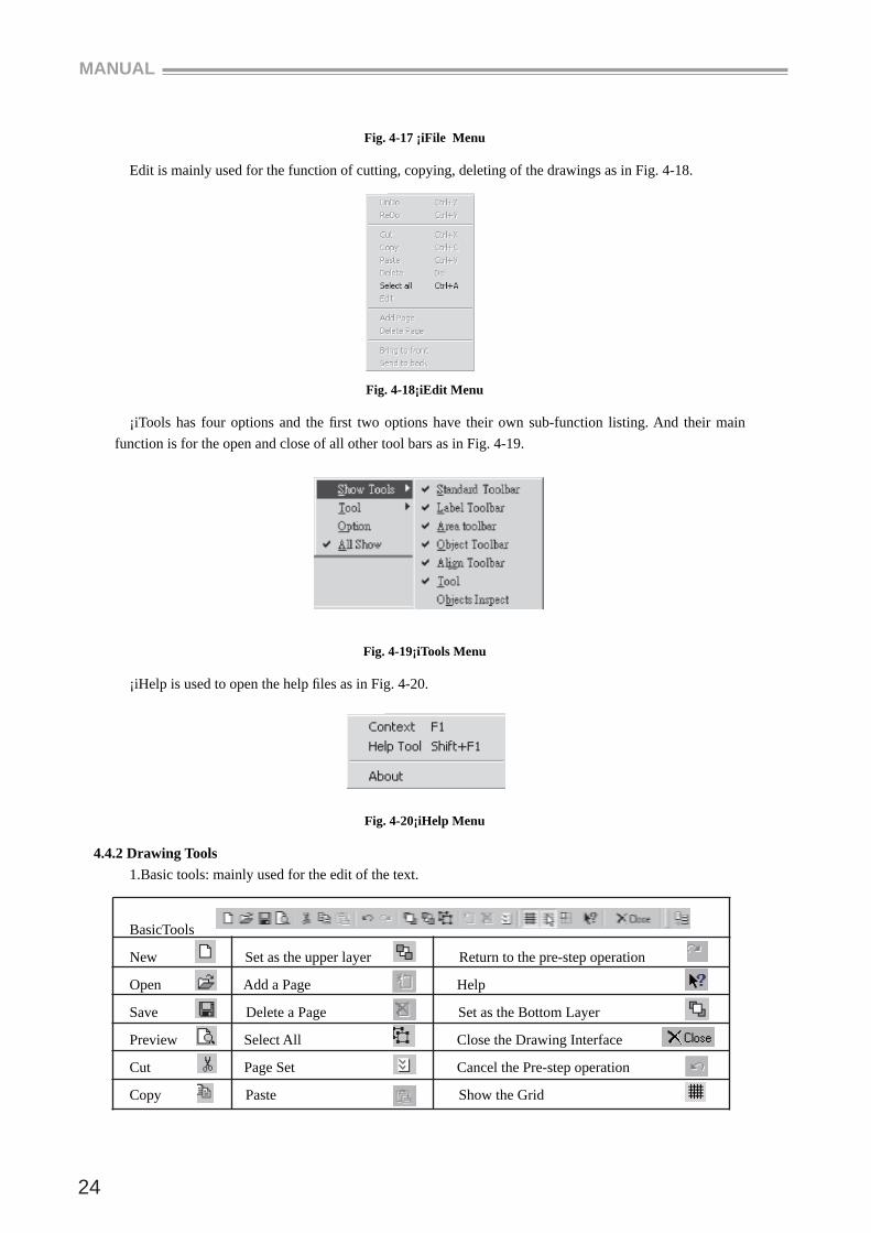
File is mainly used for fi les management, such as New, Open, Save and Page Set as in Fig. 4-17.
MANUAL
24
Fig. 4-17 ¡iFile Menu
Edit is mainly used for the function of cutting, copying, deleting of the drawings as in Fig. 4-18.
Fig. 4-18¡iEdit Menu
¡iTools has four options and the fi rst two options have their own sub-function listing. And their main function is for the open and close of all other tool bars as in Fig. 4-19.
Fig. 4-19¡iTools Menu
¡iHelp is used to open the help fi les as in Fig. 4-20.
Fig. 4-20¡iHelp Menu
4.4.2 Drawing Tools1.Basic tools: mainly used for the edit of the text.
BasicTools
New Set as the upper layer Return to the pre-step operation
Open Add a Page Help
Save Delete a Page Set as the Bottom Layer
Preview Select All Close the Drawing Interface
Cut Page Set Cancel the Pre-step operation
Copy Paste Show the Grid
SCADA
25
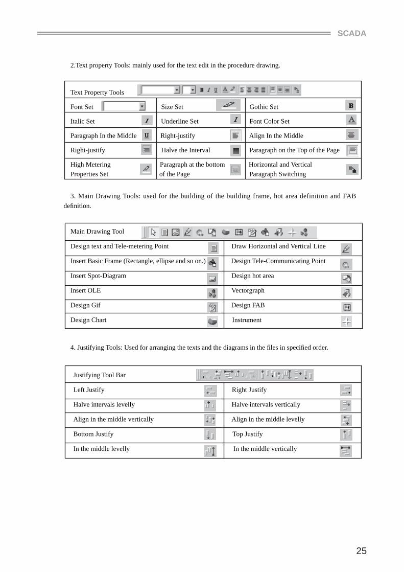
2.Text property Tools: mainly used for the text edit in the procedure drawing.
Text Property Tools
Font Set Size Set Gothic Set
Italic Set Underline Set Font Color Set
Paragraph In the Middle Right-justify Align In the Middle
Right-justify Halve the Interval Paragraph on the Top of the Page
High Metering Paragraph at the bottom Horizontal and Vertical Properties Set of the Page Paragraph Switching
3. Main Drawing Tools: used for the building of the building frame, hot area definition and FAB defi nition.
Main Drawing Tool
Design text and Tele-metering Point Draw Horizontal and Vertical Line
Insert Basic Frame (Rectangle, ellipse and so on.) Design Tele-Communicating Point
Insert Spot-Diagram Design hot area
Insert OLE Vectorgraph
Design Gif Design FAB
Design Chart Instrument
4. Justifying Tools: Used for arranging the texts and the diagrams in the fi les in specifi ed order.
Justifying Tool Bar
Left Justify Right Justify
Halve intervals levelly Halve intervals vertically
Align in the middle vertically Align in the middle levelly
Bottom Justify Top Justify
In the middle levelly In the middle vertically
MANUAL
26
5. Grids Setting Tools: Used for the frame lines and the colors of the diagrams setting.
Internet Setting Tools
Top line rim Bottom line rim
Right line rim Left line rim
Whole line rim Cancel line rim
Set drawing pen color Set drawing pen width
Set the color degree of the form background
4.4.3 Drawing the Monitoring Diagram
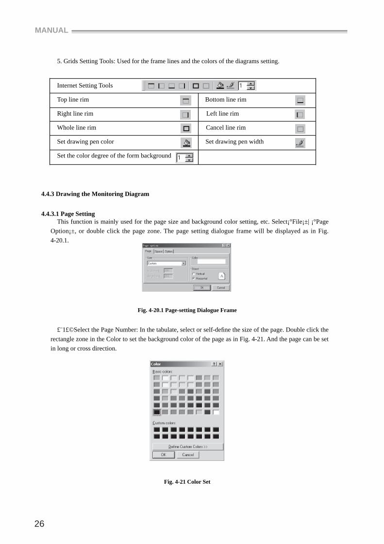
4.4.3.1 Page SettingThis function is mainly used for the page size and background color setting, etc. Select¡°File¡±| ¡°Page
Option¡±, or double click the page zone. The page setting dialogue frame will be displayed as in Fig. 4-20.1.
Fig. 4-20.1 Page-setting Dialogue Frame
£¨1£©Select the Page Number: In the tabulate, select or self-defi ne the size of the page. Double click the rectangle zone in the Color to set the background color of the page as in Fig. 4-21. And the page can be set in long or cross direction.
Fig. 4-21 Color Set
SCADA
27
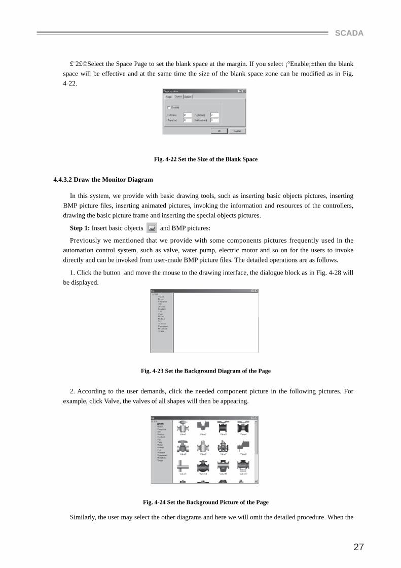
£¨2£©Select the Space Page to set the blank space at the margin. If you select ¡°Enable¡±then the blank space will be effective and at the same time the size of the blank space zone can be modifi ed as in Fig. 4-22.
Fig. 4-22 Set the Size of the Blank Space
4.4.3.2 Draw the Monitor Diagram
In this system, we provide with basic drawing tools, such as inserting basic objects pictures, inserting BMP picture fi les, inserting animated pictures, invoking the information and resources of the controllers, drawing the basic picture frame and inserting the special objects pictures.
Step 1: Insert basic objects and BMP pictures:
Previously we mentioned that we provide with some components pictures frequently used in the automation control system, such as valve, water pump, electric motor and so on for the users to invoke directly and can be invoked from user-made BMP picture fi les. The detailed operations are as follows.
1. Click the button and move the mouse to the drawing interface, the dialogue block as in Fig. 4-28 will be displayed.
Fig. 4-23 Set the Background Diagram of the Page
2. According to the user demands, click the needed component picture in the following pictures. For example, click Valve, the valves of all shapes will then be appearing.
Fig. 4-24 Set the Background Picture of the Page
Similarly, the user may select the other diagrams and here we will omit the detailed procedure. When the
MANUAL
28
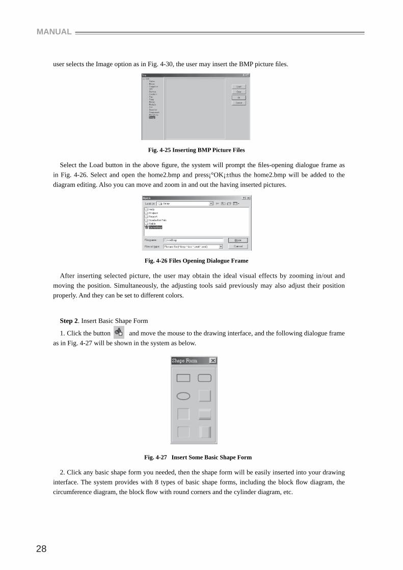
user selects the Image option as in Fig. 4-30, the user may insert the BMP picture fi les.
Fig. 4-25 Inserting BMP Picture Files
Select the Load button in the above fi gure, the system will prompt the fi les-opening dialogue frame as in Fig. 4-26. Select and open the home2.bmp and press¡°OK¡±thus the home2.bmp will be added to the diagram editing. Also you can move and zoom in and out the having inserted pictures.
Fig. 4-26 Files Opening Dialogue Frame
After inserting selected picture, the user may obtain the ideal visual effects by zooming in/out and moving the position. Simultaneously, the adjusting tools said previously may also adjust their position properly. And they can be set to different colors.
Step 2. Insert Basic Shape Form
1. Click the button and move the mouse to the drawing interface, and the following dialogue frame as in Fig. 4-27 will be shown in the system as below.
Fig. 4-27 Insert Some Basic Shape Form
2. Click any basic shape form you needed, then the shape form will be easily inserted into your drawing interface. The system provides with 8 types of basic shape forms, including the block fl ow diagram, the circumference diagram, the block fl ow with round corners and the cylinder diagram, etc.
SCADA
29
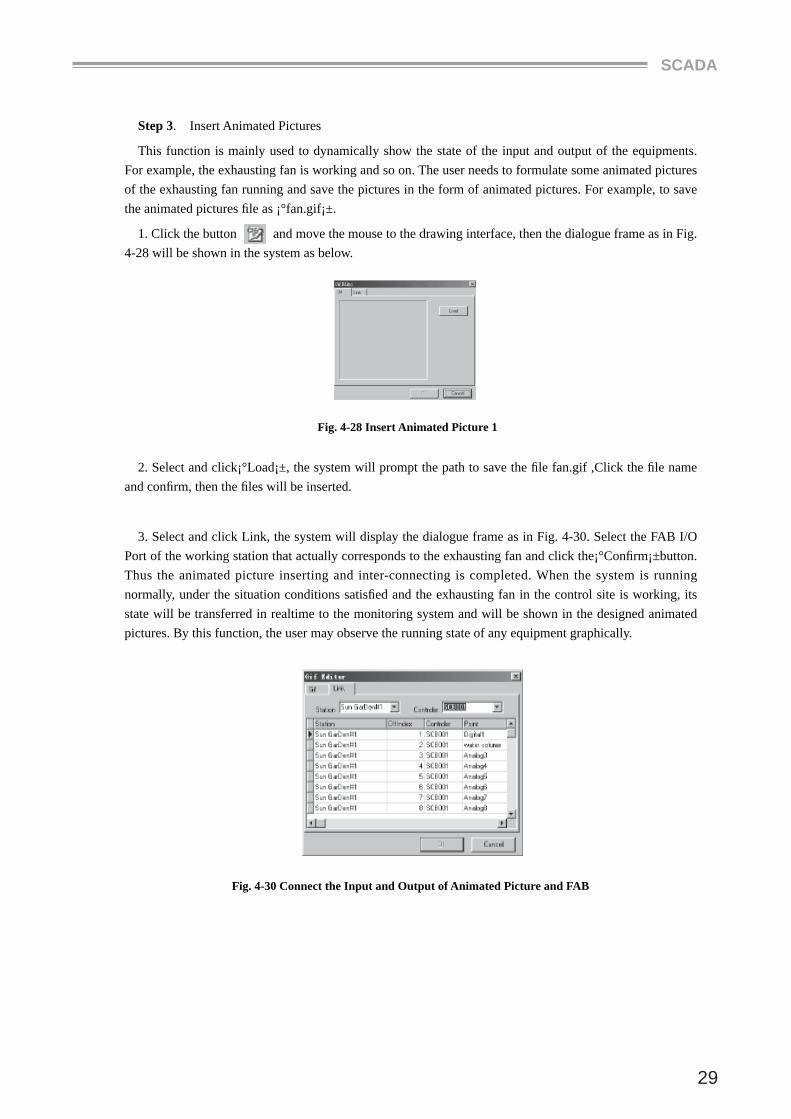
Step 3. Insert Animated Pictures
This function is mainly used to dynamically show the state of the input and output of the equipments. For example, the exhausting fan is working and so on. The user needs to formulate some animated pictures of the exhausting fan running and save the pictures in the form of animated pictures. For example, to save the animated pictures fi le as ¡°fan.gif¡±.
1. Click the button and move the mouse to the drawing interface, then the dialogue frame as in Fig. 4-28 will be shown in the system as below.
Fig. 4-28 Insert Animated Picture 1
2. Select and click¡°Load¡±, the system will prompt the path to save the fi le fan.gif ,Click the fi le name and confi rm, then the fi les will be inserted.
3. Select and click Link, the system will display the dialogue frame as in Fig. 4-30. Select the FAB I/O Port of the working station that actually corresponds to the exhausting fan and click the¡°Confi rm¡±button. Thus the animated picture inserting and inter-connecting is completed. When the system is running normally, under the situation conditions satisfi ed and the exhausting fan in the control site is working, its state will be transferred in realtime to the monitoring system and will be shown in the designed animated pictures. By this function, the user may observe the running state of any equipment graphically.
Fig. 4-30 Connect the Input and Output of Animated Picture and FAB
MANUAL
30
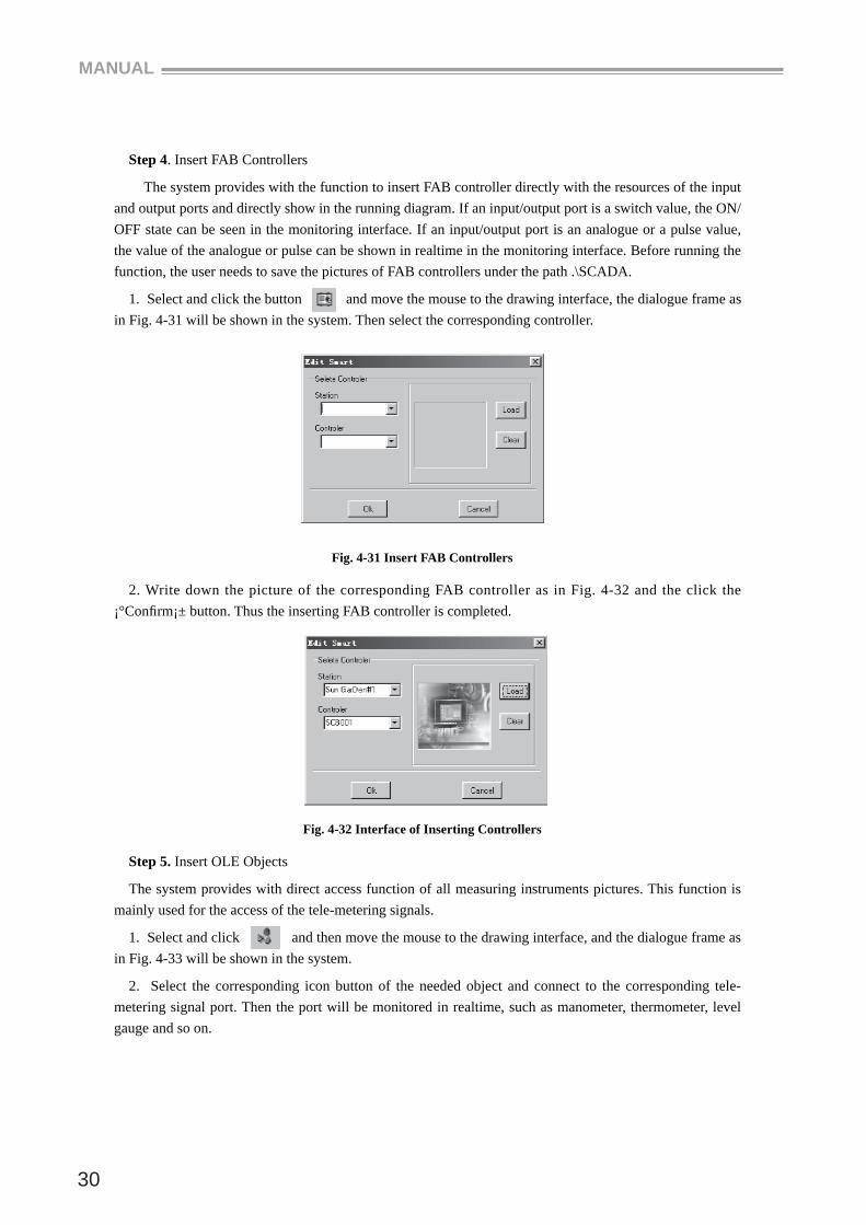
Step 4. Insert FAB Controllers
The system provides with the function to insert FAB controller directly with the resources of the input and output ports and directly show in the running diagram. If an input/output port is a switch value, the ON/OFF state can be seen in the monitoring interface. If an input/output port is an analogue or a pulse value, the value of the analogue or pulse can be shown in realtime in the monitoring interface. Before running the function, the user needs to save the pictures of FAB controllers under the path .\SCADA.
1. Select and click the button and move the mouse to the drawing interface, the dialogue frame as in Fig. 4-31 will be shown in the system. Then select the corresponding controller.
Fig. 4-31 Insert FAB Controllers
2. Write down the picture of the corresponding FAB controller as in Fig. 4-32 and the click the ¡°Confi rm¡± button. Thus the inserting FAB controller is completed.
Fig. 4-32 Interface of Inserting Controllers
Step 5. Insert OLE Objects
The system provides with direct access function of all measuring instruments pictures. This function is mainly used for the access of the tele-metering signals.
1. Select and click and then move the mouse to the drawing interface, and the dialogue frame as in Fig. 4-33 will be shown in the system.
2. Select the corresponding icon button of the needed object and connect to the corresponding tele-metering signal port. Then the port will be monitored in realtime, such as manometer, thermometer, level gauge and so on.
SCADA
31
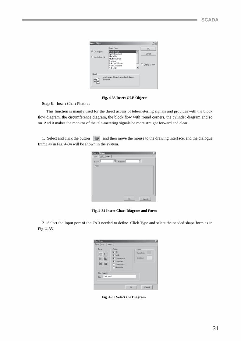
Fig. 4-33 Insert OLE ObjectsStep 6. Insert Chart Pictures
This function is mainly used for the direct access of tele-metering signals and provides with the block fl ow diagram, the circumference diagram, the block fl ow with round corners, the cylinder diagram and so on. And it makes the monitor of the tele-metering signals be more straight forward and clear.
1. Select and click the button and then move the mouse to the drawing interface, and the dialogue frame as in Fig. 4-34 will be shown in the system.
Fig. 4-34 Insert Chart Diagram and Form
2. Select the Input port of the FAB needed to defi ne. Click Type and select the needed shape form as in Fig. 4-35.
Fig. 4-35 Select the Diagram
MANUAL
32
3. Press the ¡°Confi rm¡±button to confi rm and the setup is completed. During the normal execution of the system, the diagram will be shown as the analogue value received from the site.
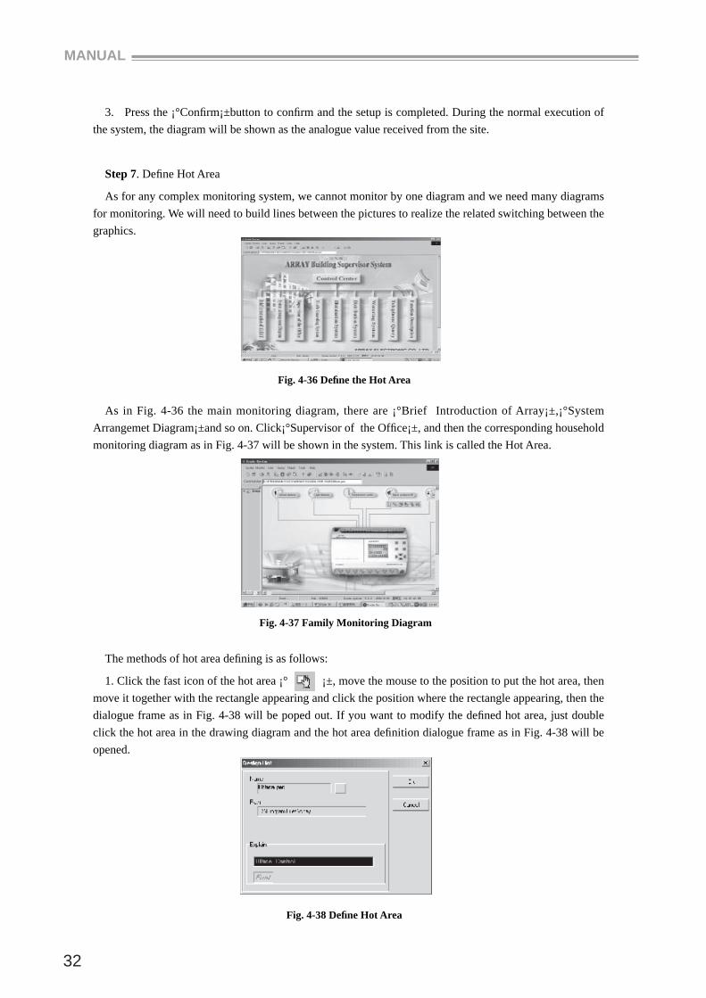
Step 7. Defi ne Hot Area
As for any complex monitoring system, we cannot monitor by one diagram and we need many diagrams for monitoring. We will need to build lines between the pictures to realize the related switching between the graphics.
Fig. 4-36 Defi ne the Hot Area
As in Fig. 4-36 the main monitoring diagram, there are ¡°Brief Introduction of Array¡±,¡°System Arrangemet Diagram¡±and so on. Click¡°Supervisor of the Offi ce¡±, and then the corresponding household monitoring diagram as in Fig. 4-37 will be shown in the system. This link is called the Hot Area.
Fig. 4-37 Family Monitoring Diagram
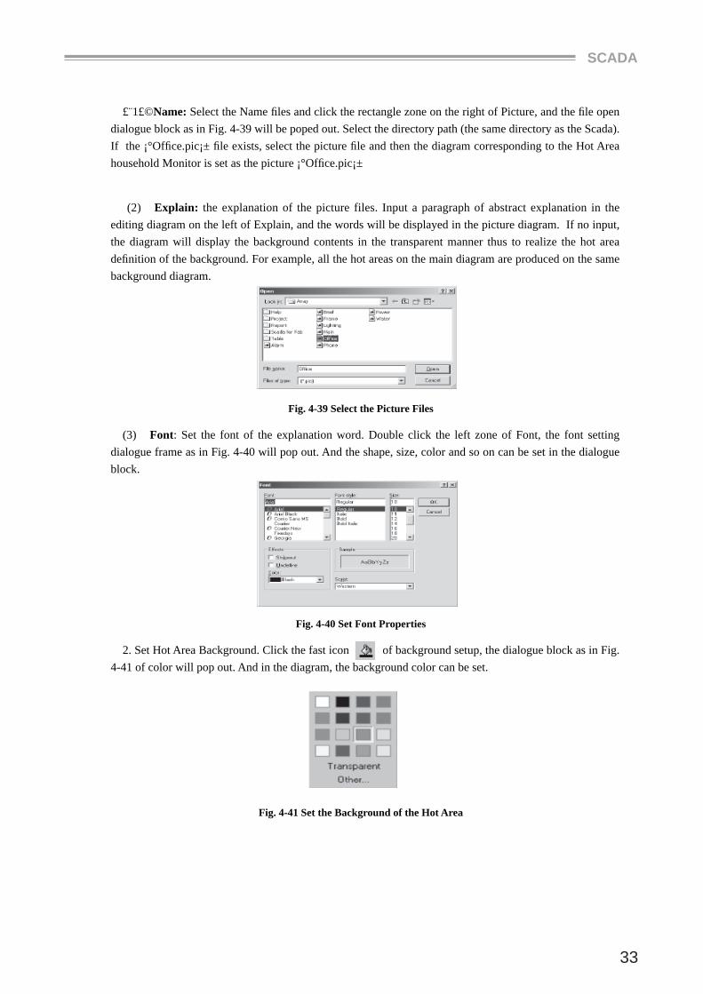
The methods of hot area defi ning is as follows:
1. Click the fast icon of the hot area ¡° ¡±, move the mouse to the position to put the hot area, then move it together with the rectangle appearing and click the position where the rectangle appearing, then the dialogue frame as in Fig. 4-38 will be poped out. If you want to modify the defi ned hot area, just double click the hot area in the drawing diagram and the hot area defi nition dialogue frame as in Fig. 4-38 will be opened.
Fig. 4-38 Defi ne Hot Area
SCADA
33
£¨1£©Name: Select the Name fi les and click the rectangle zone on the right of Picture, and the fi le open dialogue block as in Fig. 4-39 will be poped out. Select the directory path (the same directory as the Scada). If the ¡°Offi ce.pic¡± fi le exists, select the picture fi le and then the diagram corresponding to the Hot Area household Monitor is set as the picture ¡°Offi ce.pic¡±
(2) Explain: the explanation of the picture files. Input a paragraph of abstract explanation in the editing diagram on the left of Explain, and the words will be displayed in the picture diagram. If no input, the diagram will display the background contents in the transparent manner thus to realize the hot area defi nition of the background. For example, all the hot areas on the main diagram are produced on the same background diagram.
Fig. 4-39 Select the Picture Files
(3) Font: Set the font of the explanation word. Double click the left zone of Font, the font setting dialogue frame as in Fig. 4-40 will pop out. And the shape, size, color and so on can be set in the dialogue block.
Fig. 4-40 Set Font Properties
2. Set Hot Area Background. Click the fast icon of background setup, the dialogue block as in Fig. 4-41 of color will pop out. And in the diagram, the background color can be set.
Fig. 4-41 Set the Background of the Hot Area
MANUAL
34
Step 8. Setup the Input and Output
After editing a monitoring diagram, it is needed to show all the information of all the input and output ports of the FAB in the diagram to achieve monitoring action. As for different signal port such as tele-communicating, tele-metering and tele-pulsating, we have different setup methods and the details are as follows:
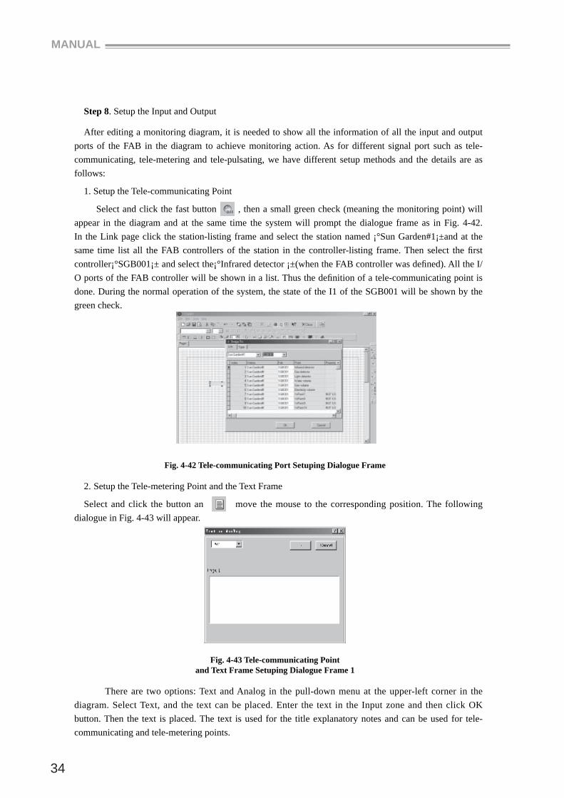
1. Setup the Tele-communicating Point
Select and click the fast button , then a small green check (meaning the monitoring point) will appear in the diagram and at the same time the system will prompt the dialogue frame as in Fig. 4-42. In the Link page click the station-listing frame and select the station named ¡°Sun Garden#1¡±and at the same time list all the FAB controllers of the station in the controller-listing frame. Then select the fi rst controller¡°SGB001¡± and select the¡°Infrared detector ¡±(when the FAB controller was defi ned). All the I/O ports of the FAB controller will be shown in a list. Thus the defi nition of a tele-communicating point is done. During the normal operation of the system, the state of the I1 of the SGB001 will be shown by the green check.
Fig. 4-42 Tele-communicating Port Setuping Dialogue Frame
2. Setup the Tele-metering Point and the Text Frame
Select and click the button an move the mouse to the corresponding position. The following dialogue in Fig. 4-43 will appear.
Fig. 4-43 Tele-communicating Point and Text Frame Setuping Dialogue Frame 1
There are two options: Text and Analog in the pull-down menu at the upper-left corner in the diagram. Select Text, and the text can be placed. Enter the text in the Input zone and then click OK button. Then the text is placed. The text is used for the title explanatory notes and can be used for tele-communicating and tele-metering points.
SCADA
35
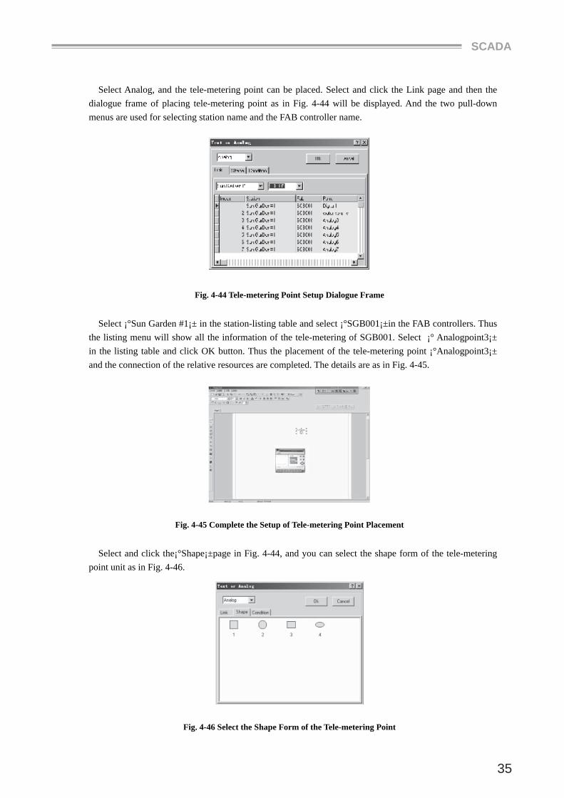
Select Analog, and the tele-metering point can be placed. Select and click the Link page and then the dialogue frame of placing tele-metering point as in Fig. 4-44 will be displayed. And the two pull-down menus are used for selecting station name and the FAB controller name.
Fig. 4-44 Tele-metering Point Setup Dialogue Frame
Select ¡°Sun Garden #1¡± in the station-listing table and select ¡°SGB001¡±in the FAB controllers. Thus the listing menu will show all the information of the tele-metering of SGB001. Select ¡° Analogpoint3¡± in the listing table and click OK button. Thus the placement of the tele-metering point ¡°Analogpoint3¡± and the connection of the relative resources are completed. The details are as in Fig. 4-45.
Fig. 4-45 Complete the Setup of Tele-metering Point Placement
Select and click the¡°Shape¡±page in Fig. 4-44, and you can select the shape form of the tele-metering point unit as in Fig. 4-46.
Fig. 4-46 Select the Shape Form of the Tele-metering Point
MANUAL
36
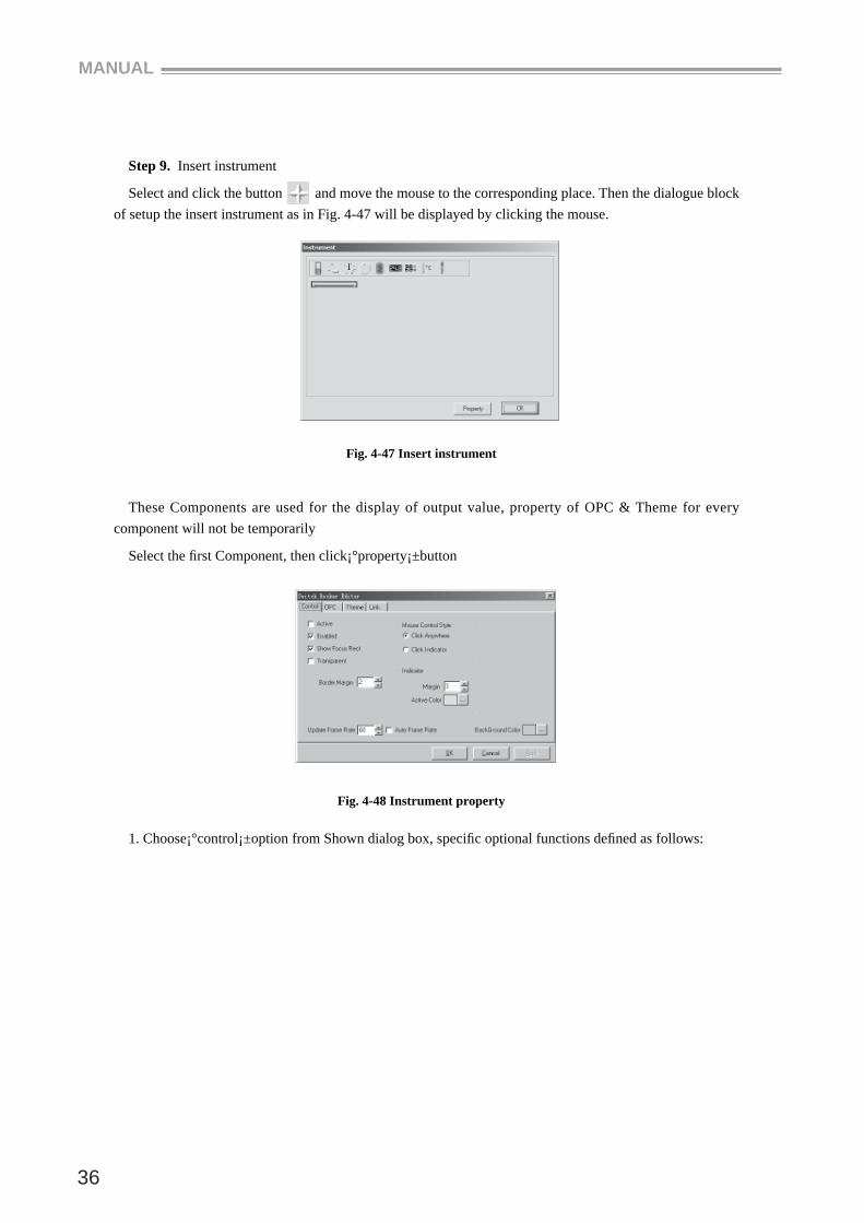
Step 9. Insert instrument
Select and click the button and move the mouse to the corresponding place. Then the dialogue block of setup the insert instrument as in Fig. 4-47 will be displayed by clicking the mouse.
Fig. 4-47 Insert instrument
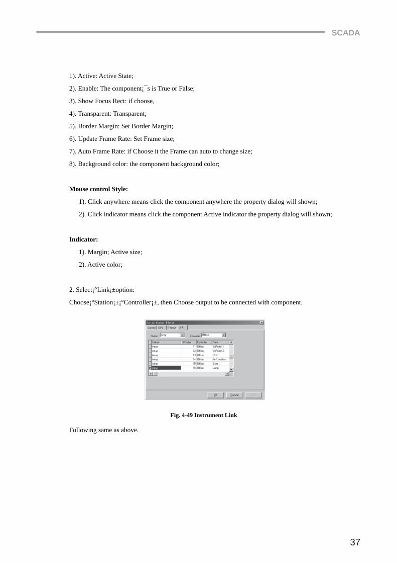
These Components are used for the display of output value, property of OPC & Theme for every component will not be temporarily
Select the fi rst Component, then click¡°property¡±button
Fig. 4-48 Instrument property
1. Choose¡°control¡±option from Shown dialog box, specifi c optional functions defi ned as follows:
SCADA
37
1). Active: Active State;
2). Enable: The component¡¯s is True or False;
3). Show Focus Rect: if choose,
4). Transparent: Transparent;
5). Border Margin: Set Border Margin;
6). Update Frame Rate: Set Frame size;
7). Auto Frame Rate: if Choose it the Frame can auto to change size;
8). Background color: the component background color;
Mouse control Style:
1). Click anywhere means click the component anywhere the property dialog will shown;
2). Click indicator means click the component Active indicator the property dialog will shown;
Indicator:
1). Margin; Active size;
2). Active color;
2. Select¡°Link¡±option:
Choose¡°Station¡±¡°Controller¡±, then Choose output to be connected with component.
Fig. 4-49 Instrument Link
Following same as above.
MANUAL
38
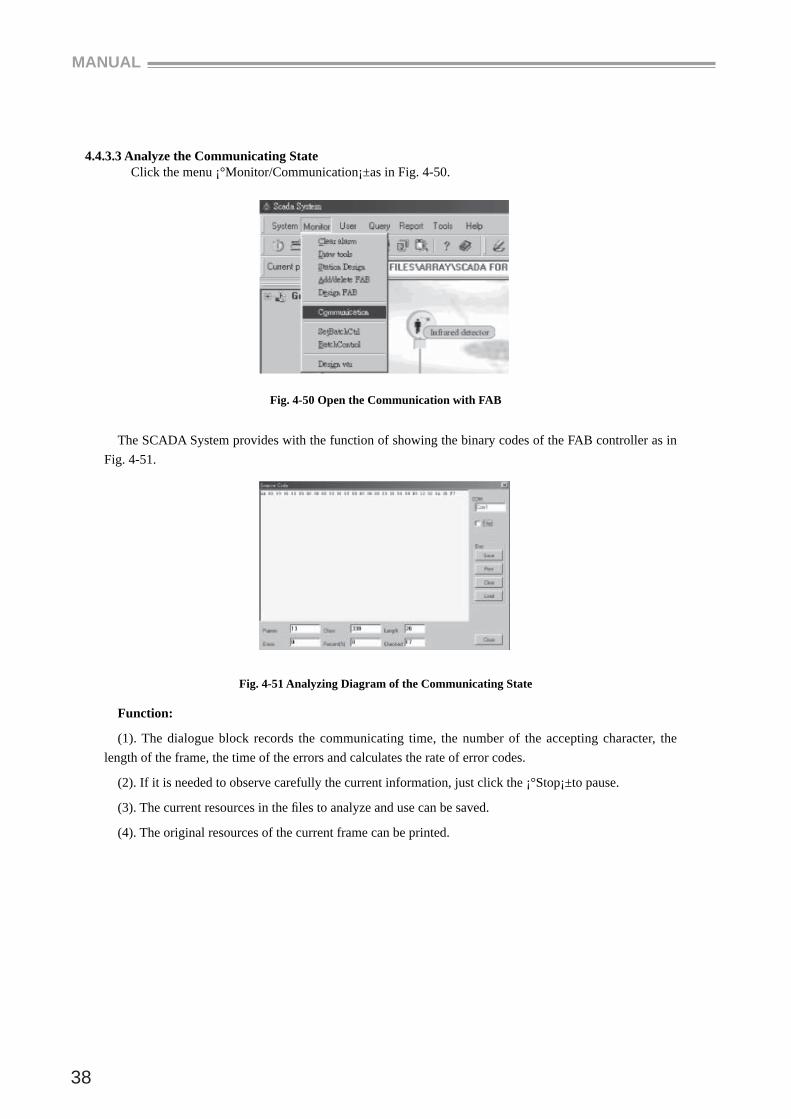
4.4.3.3 Analyze the Communicating State Click the menu ¡°Monitor/Communication¡±as in Fig. 4-50.
Fig. 4-50 Open the Communication with FAB
The SCADA System provides with the function of showing the binary codes of the FAB controller as in Fig. 4-51.
Fig. 4-51 Analyzing Diagram of the Communicating State
Function:
(1). The dialogue block records the communicating time, the number of the accepting character, the length of the frame, the time of the errors and calculates the rate of error codes.
(2). If it is needed to observe carefully the current information, just click the ¡°Stop¡±to pause.
(3). The current resources in the fi les to analyze and use can be saved.
(4). The original resources of the current frame can be printed.
SCADA
39
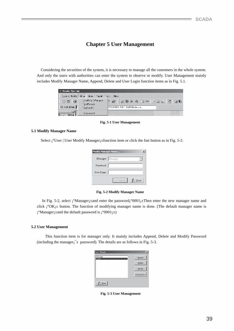
Chapter 5 User Management
Considering the securities of the system, it is necessary to manage all the customers in the whole system. And only the users with authorities can enter the system to observe or modify. User Management mainly includes Modify Manager Name, Append, Delete and User Login function items as in Fig. 5.1.
Fig. 5-1 User Management
5.1 Modify Manager Name
Select ¡°User | User Modify Manager¡±function item or click the fast button as in Fig. 5-2.
Fig. 5-2 Modify Manager Name
In Fig. 5-2, select ¡°Manager¡±and enter the password¡°0001¡±Then enter the new manager name and click ¡°OK¡± button. The function of modifying manager name is done. (The default manager name is ¡°Manager¡±and the default password is ¡°0001¡±)
5.2 User Management
This function item is for manager only. It mainly includes Append, Delete and Modify Password (including the manager¡¯s password). The details are as follows in Fig. 5-3.
Fig. 5-3 User Management
MANUAL
40
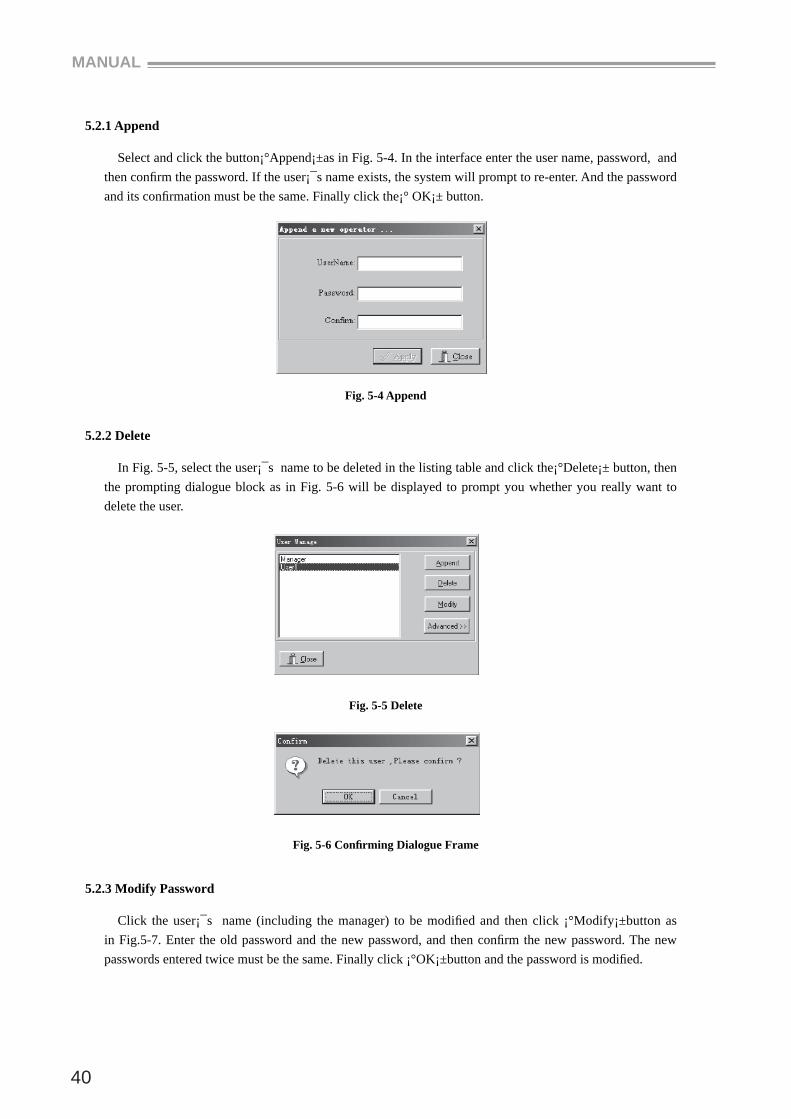
5.2.1 Append
Select and click the button¡°Append¡±as in Fig. 5-4. In the interface enter the user name, password, and then confi rm the password. If the user¡¯s name exists, the system will prompt to re-enter. And the password and its confi rmation must be the same. Finally click the¡° OK¡± button.
Fig. 5-4 Append
5.2.2 Delete
In Fig. 5-5, select the user¡¯s name to be deleted in the listing table and click the¡°Delete¡± button, then the prompting dialogue block as in Fig. 5-6 will be displayed to prompt you whether you really want to delete the user.
Fig. 5-5 Delete
Fig. 5-6 Confi rming Dialogue Frame
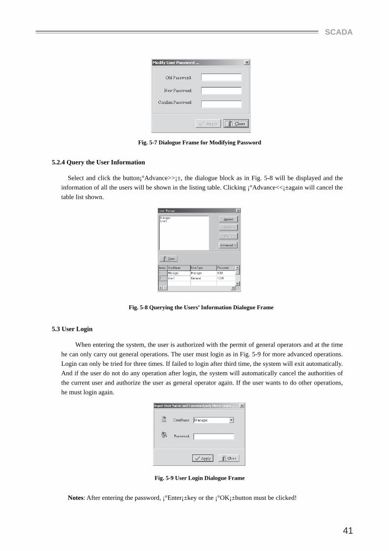
5.2.3 Modify Password
Click the user¡¯s name (including the manager) to be modifi ed and then click ¡°Modify¡±button as in Fig.5-7. Enter the old password and the new password, and then confi rm the new password. The new passwords entered twice must be the same. Finally click ¡°OK¡±button and the password is modifi ed.
SCADA
41
Fig. 5-7 Dialogue Frame for Modifying Password
5.2.4 Query the User Information
Select and click the button¡°Advance>>¡±, the dialogue block as in Fig. 5-8 will be displayed and the information of all the users will be shown in the listing table. Clicking ¡°Advance<<¡±again will cancel the table list shown.
Fig. 5-8 Querying the Users’ Information Dialogue Frame
5.3 User Login
When entering the system, the user is authorized with the permit of general operators and at the time he can only carry out general operations. The user must login as in Fig. 5-9 for more advanced operations. Login can only be tried for three times. If failed to login after third time, the system will exit automatically. And if the user do not do any operation after login, the system will automatically cancel the authorities of the current user and authorize the user as general operator again. If the user wants to do other operations, he must login again.
Fig. 5-9 User Login Dialogue Frame
Notes: After entering the password, ¡°Enter¡±key or the ¡°OK¡±button must be clicked!
MANUAL
42
5.4 User Logout
User will need to logout when the user is out of offi ce and it is needed to login when other users are in offi ce. Thus it guarantees the securities of the system.
5.5 Explanations for User Authorities
Manager (one only): Having all the functions.
General User (may be several): Not having the following function.
[Deploy] [Clear Alarm] [Draw Tools] [Station Design]
[Add/Delete Fab] [Design Fab ] [BatchControl]
[UserModifyManager] [UserManage] [Backup DB] [Create Report]
User with Lowest Authorities (Non User):
[Deploy] [Clear Alarm] [Draw Tools] [Station Design]
[Add/Delete Fab] [Design Fab ] [BatchControl]
[UserModifyManager] [UserManage] [Backup DB] [Create Report]
[Set FabTime]
Explanation: When the system being entering or the users logout, the system will automatically be set to the state of lowest authorities.
SCADA
43
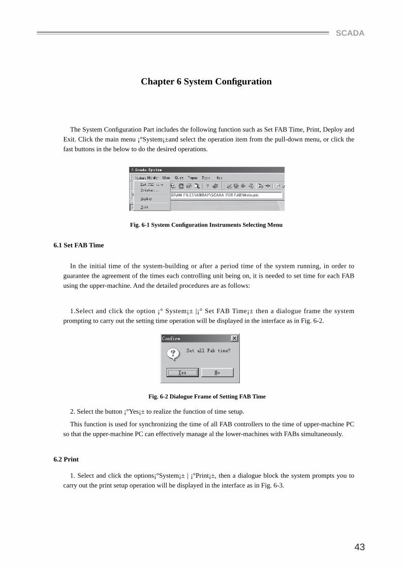
Chapter 6 System Confi guration
The System Confi guration Part includes the following function such as Set FAB Time, Print, Deploy and Exit. Click the main menu ¡°System¡±and select the operation item from the pull-down menu, or click the fast buttons in the below to do the desired operations.
Fig. 6-1 System Confi guration Instruments Selecting Menu
6.1 Set FAB Time
In the initial time of the system-building or after a period time of the system running, in order to guarantee the agreement of the times each controlling unit being on, it is needed to set time for each FAB using the upper-machine. And the detailed procedures are as follows:
1.Select and click the option ¡° System¡± |¡° Set FAB Time¡± then a dialogue frame the system prompting to carry out the setting time operation will be displayed in the interface as in Fig. 6-2.
Fig. 6-2 Dialogue Frame of Setting FAB Time
2. Select the button ¡°Yes¡± to realize the function of time setup.
This function is used for synchronizing the time of all FAB controllers to the time of upper-machine PC so that the upper-machine PC can effectively manage al the lower-machines with FABs simultaneously.
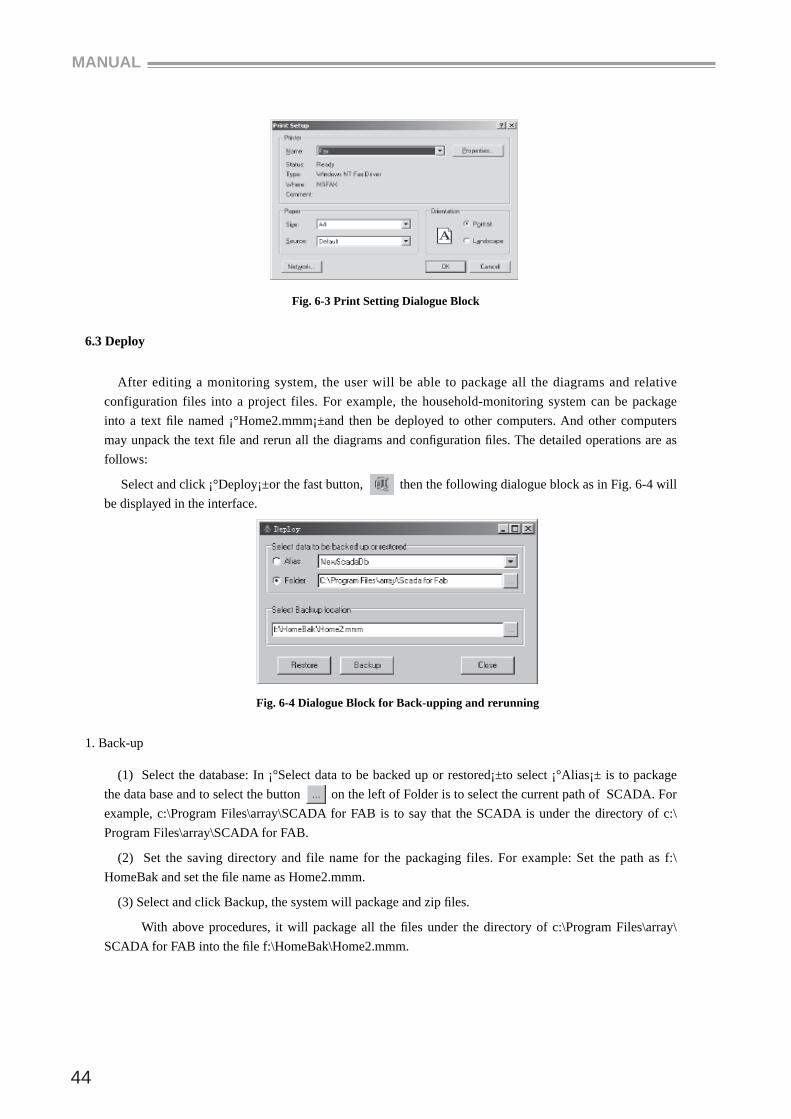
6.2 Print
1. Select and click the options¡°System¡± | ¡°Print¡±, then a dialogue block the system prompts you to carry out the print setup operation will be displayed in the interface as in Fig. 6-3.
MANUAL
44
Fig. 6-3 Print Setting Dialogue Block
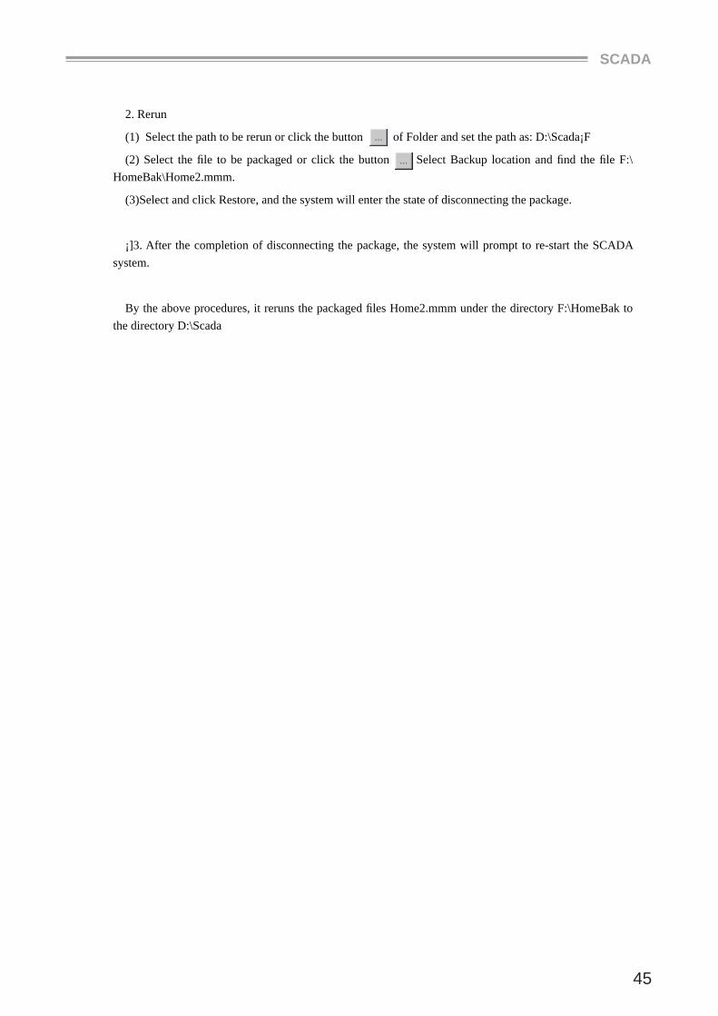
6.3 Deploy
After editing a monitoring system, the user will be able to package all the diagrams and relative configuration files into a project files. For example, the household-monitoring system can be package into a text fi le named ¡°Home2.mmm¡±and then be deployed to other computers. And other computers may unpack the text fi le and rerun all the diagrams and confi guration fi les. The detailed operations are as follows:
Select and click ¡°Deploy¡±or the fast button, then the following dialogue block as in Fig. 6-4 will be displayed in the interface.
Fig. 6-4 Dialogue Block for Back-upping and rerunning
1. Back-up
(1) Select the database: In ¡°Select data to be backed up or restored¡±to select ¡°Alias¡± is to package the data base and to select the button on the left of Folder is to select the current path of SCADA. For example, c:\Program Files\array\SCADA for FAB is to say that the SCADA is under the directory of c:\Program Files\array\SCADA for FAB.
(2) Set the saving directory and file name for the packaging files. For example: Set the path as f:\HomeBak and set the fi le name as Home2.mmm.
(3) Select and click Backup, the system will package and zip fi les.
With above procedures, it will package all the fi les under the directory of c:\Program Files\array\SCADA for FAB into the fi le f:\HomeBak\Home2.mmm.
SCADA
45
2. Rerun
(1) Select the path to be rerun or click the button of Folder and set the path as: D:\Scada¡F
(2) Select the fi le to be packaged or click the button Select Backup location and fi nd the fi le F:\HomeBak\Home2.mmm.
(3)Select and click Restore, and the system will enter the state of disconnecting the package.
¡]3. After the completion of disconnecting the package, the system will prompt to re-start the SCADA system.
By the above procedures, it reruns the packaged fi les Home2.mmm under the directory F:\HomeBak to the directory D:\Scada
MANUAL
46
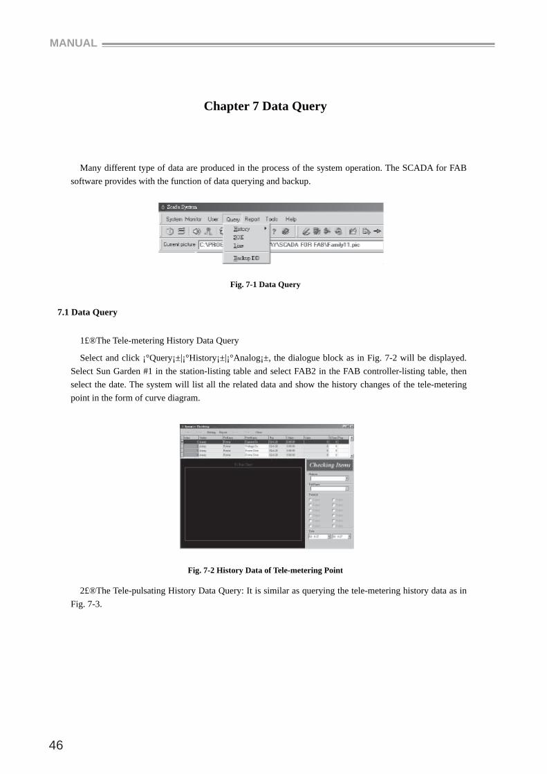
Chapter 7 Data Query
Many different type of data are produced in the process of the system operation. The SCADA for FAB software provides with the function of data querying and backup.
Fig. 7-1 Data Query
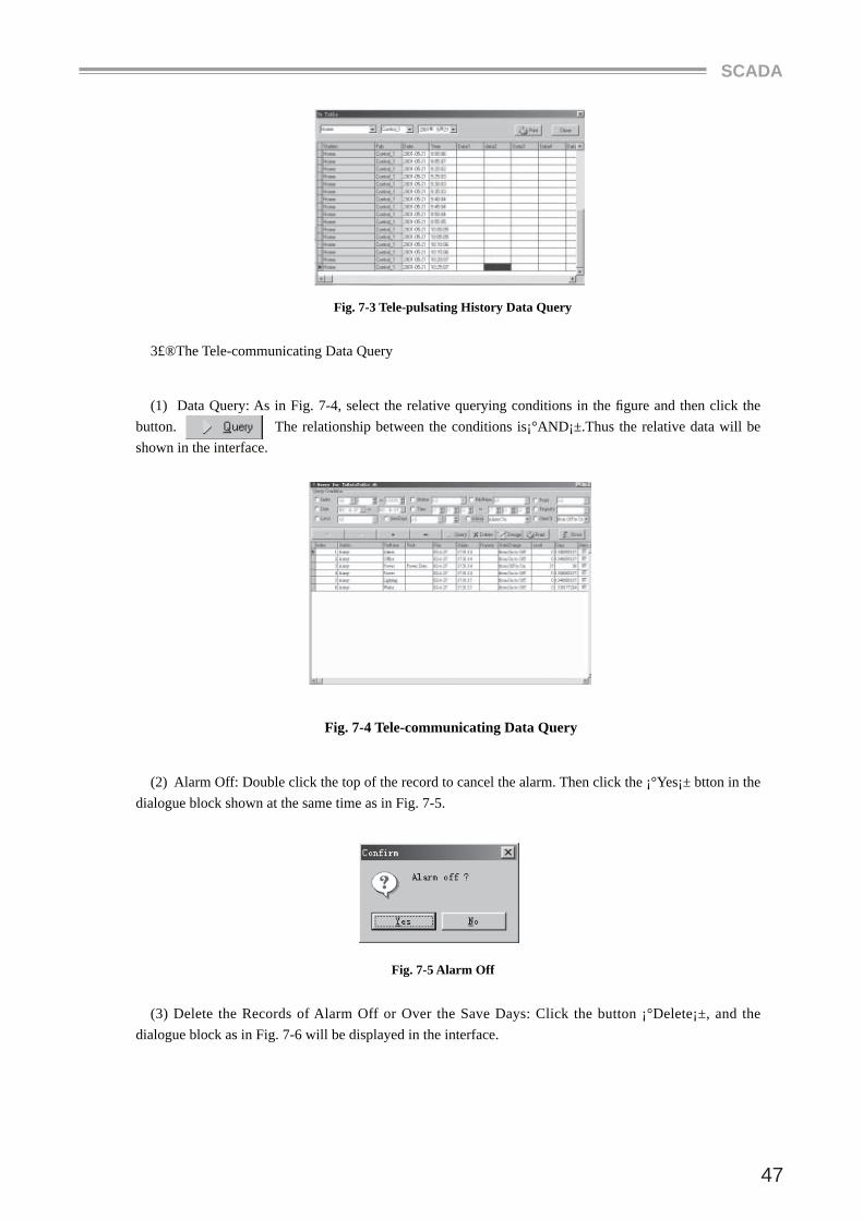
7.1 Data Query
1£®The Tele-metering History Data Query
Select and click ¡°Query¡±|¡°History¡±|¡°Analog¡±, the dialogue block as in Fig. 7-2 will be displayed. Select Sun Garden #1 in the station-listing table and select FAB2 in the FAB controller-listing table, then select the date. The system will list all the related data and show the history changes of the tele-metering point in the form of curve diagram.
Fig. 7-2 History Data of Tele-metering Point
2£®The Tele-pulsating History Data Query: It is similar as querying the tele-metering history data as in Fig. 7-3.
SCADA
47
Fig. 7-3 Tele-pulsating History Data Query
3£®The Tele-communicating Data Query
(1) Data Query: As in Fig. 7-4, select the relative querying conditions in the fi gure and then click the button. The relationship between the conditions is¡°AND¡±.Thus the relative data will be shown in the interface.
Fig. 7-4 Tele-communicating Data Query
(2) Alarm Off: Double click the top of the record to cancel the alarm. Then click the ¡°Yes¡± btton in the dialogue block shown at the same time as in Fig. 7-5.
Fig. 7-5 Alarm Off
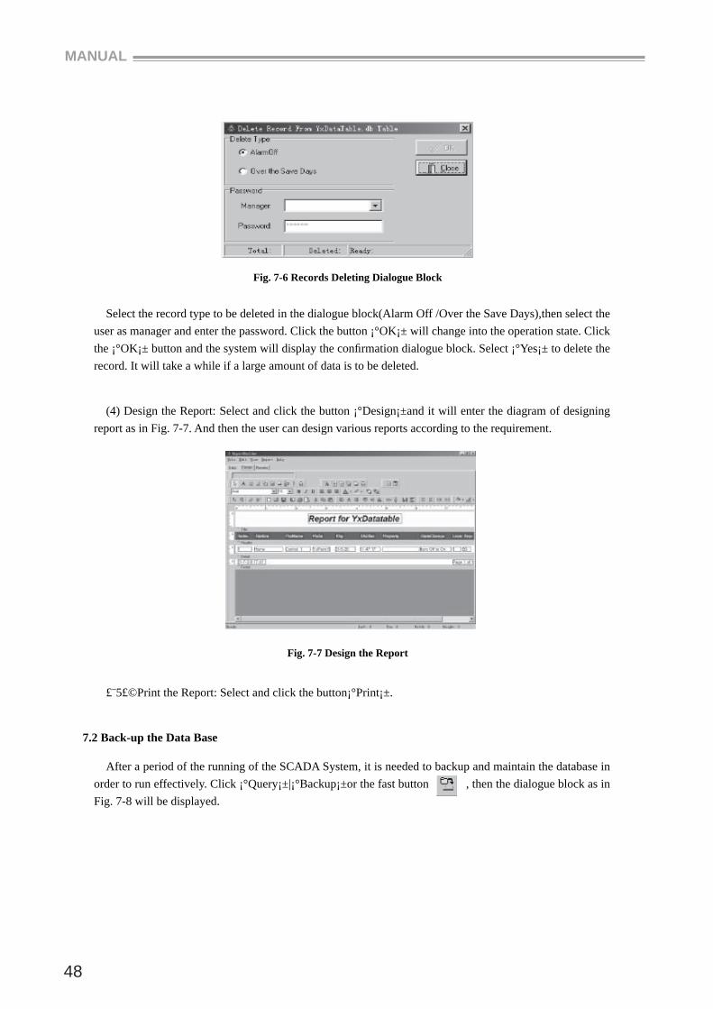
(3) Delete the Records of Alarm Off or Over the Save Days: Click the button ¡°Delete¡±, and the dialogue block as in Fig. 7-6 will be displayed in the interface.
MANUAL
48
Fig. 7-6 Records Deleting Dialogue Block
Select the record type to be deleted in the dialogue block(Alarm Off /Over the Save Days),then select the user as manager and enter the password. Click the button ¡°OK¡± will change into the operation state. Click the ¡°OK¡± button and the system will display the confi rmation dialogue block. Select ¡°Yes¡± to delete the record. It will take a while if a large amount of data is to be deleted.
(4) Design the Report: Select and click the button ¡°Design¡±and it will enter the diagram of designing report as in Fig. 7-7. And then the user can design various reports according to the requirement.
Fig. 7-7 Design the Report
£¨5£©Print the Report: Select and click the button¡°Print¡±.
7.2 Back-up the Data Base
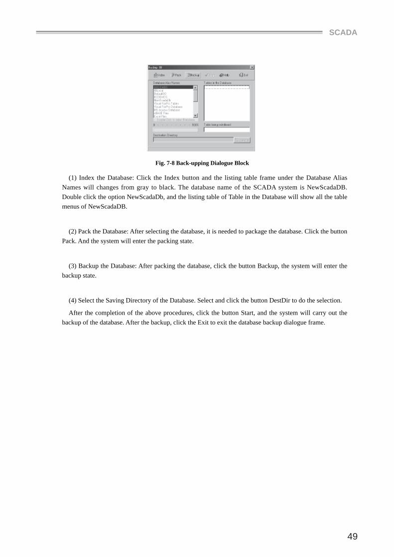
After a period of the running of the SCADA System, it is needed to backup and maintain the database in order to run effectively. Click ¡°Query¡±|¡°Backup¡±or the fast button , then the dialogue block as in Fig. 7-8 will be displayed.
SCADA
49
Fig. 7-8 Back-upping Dialogue Block
(1) Index the Database: Click the Index button and the listing table frame under the Database Alias Names will changes from gray to black. The database name of the SCADA system is NewScadaDB. Double click the option NewScadaDb, and the listing table of Table in the Database will show all the table menus of NewScadaDB.
(2) Pack the Database: After selecting the database, it is needed to package the database. Click the button Pack. And the system will enter the packing state.
(3) Backup the Database: After packing the database, click the button Backup, the system will enter the backup state.
(4) Select the Saving Directory of the Database. Select and click the button DestDir to do the selection.
After the completion of the above procedures, click the button Start, and the system will carry out the backup of the database. After the backup, click the Exit to exit the database backup dialogue frame.
MANUAL
50
Chapter 8 Report
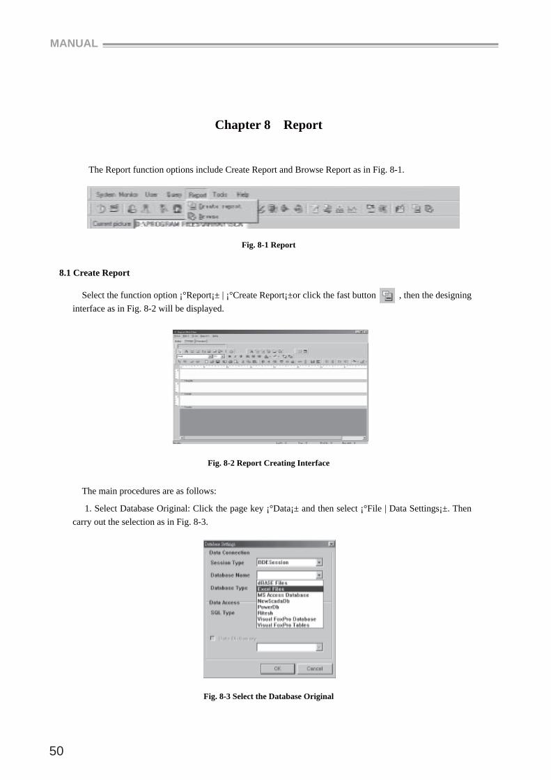
The Report function options include Create Report and Browse Report as in Fig. 8-1.
Fig. 8-1 Report
8.1 Create Report
Select the function option ¡°Report¡± | ¡°Create Report¡±or click the fast button , then the designing interface as in Fig. 8-2 will be displayed.
Fig. 8-2 Report Creating Interface
The main procedures are as follows:
1. Select Database Original: Click the page key ¡°Data¡± and then select ¡°File | Data Settings¡±. Then carry out the selection as in Fig. 8-3.
Fig. 8-3 Select the Database Original
SCADA
51
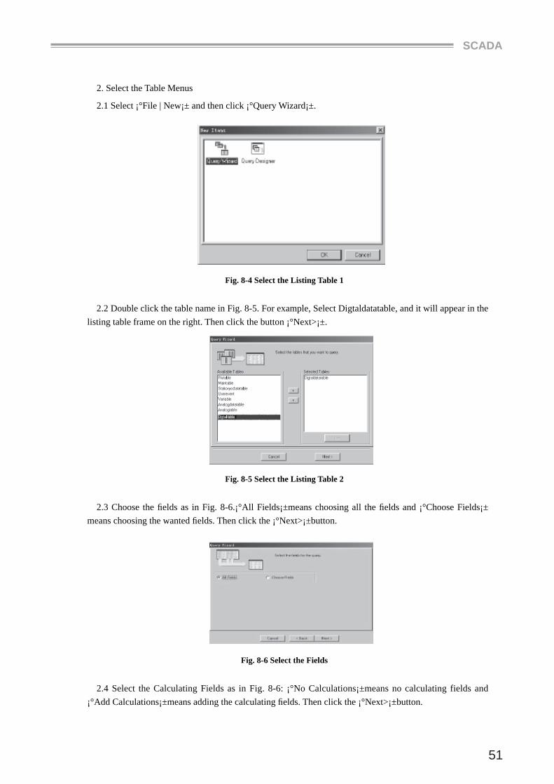
2. Select the Table Menus
2.1 Select ¡°File | New¡± and then click ¡°Query Wizard¡±.
Fig. 8-4 Select the Listing Table 1
2.2 Double click the table name in Fig. 8-5. For example, Select Digtaldatatable, and it will appear in the listing table frame on the right. Then click the button ¡°Next>¡±.
Fig. 8-5 Select the Listing Table 2
2.3 Choose the fi elds as in Fig. 8-6.¡°All Fields¡±means choosing all the fi elds and ¡°Choose Fields¡± means choosing the wanted fi elds. Then click the ¡°Next>¡±button.
Fig. 8-6 Select the Fields
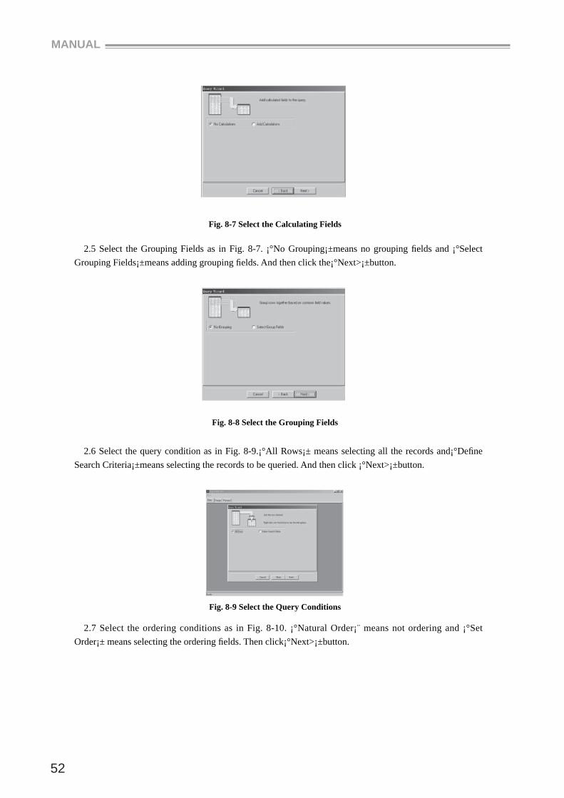
2.4 Select the Calculating Fields as in Fig. 8-6: ¡°No Calculations¡±means no calculating fields and ¡°Add Calculations¡±means adding the calculating fi elds. Then click the ¡°Next>¡±button.
MANUAL
52
Fig. 8-7 Select the Calculating Fields
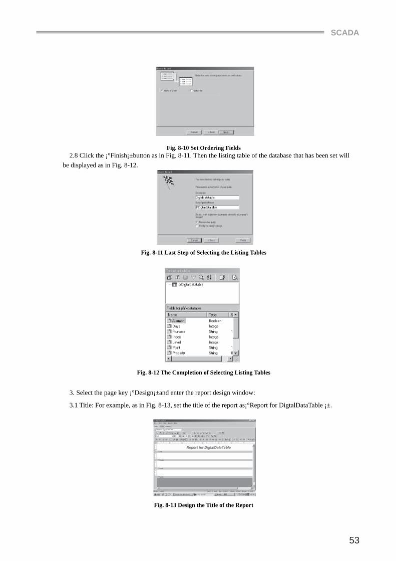
2.5 Select the Grouping Fields as in Fig. 8-7. ¡°No Grouping¡±means no grouping fi elds and ¡°Select Grouping Fields¡±means adding grouping fi elds. And then click the¡°Next>¡±button.
Fig. 8-8 Select the Grouping Fields
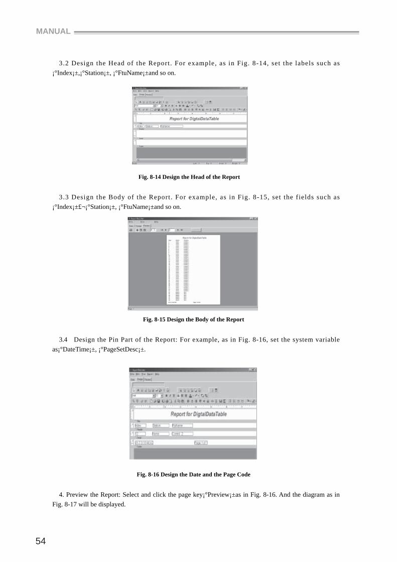
2.6 Select the query condition as in Fig. 8-9.¡°All Rows¡± means selecting all the records and¡°Defi ne Search Criteria¡±means selecting the records to be queried. And then click ¡°Next>¡±button.
Fig. 8-9 Select the Query Conditions
2.7 Select the ordering conditions as in Fig. 8-10. ¡°Natural Order¡¨ means not ordering and ¡°Set Order¡± means selecting the ordering fi elds. Then click¡°Next>¡±button.
SCADA
53
Fig. 8-10 Set Ordering Fields2.8 Click the ¡°Finish¡±button as in Fig. 8-11. Then the listing table of the database that has been set will
be displayed as in Fig. 8-12.
Fig. 8-11 Last Step of Selecting the Listing Tables
Fig. 8-12 The Completion of Selecting Listing Tables
3. Select the page key ¡°Design¡±and enter the report design window:
3.1 Title: For example, as in Fig. 8-13, set the title of the report as¡°Report for DigtalDataTable ¡±.
Fig. 8-13 Design the Title of the Report
MANUAL
54
3.2 Design the Head of the Report . For example, as in Fig. 8-14, set the labels such as ¡°Index¡±,¡°Station¡±, ¡°FtuName¡±and so on.
Fig. 8-14 Design the Head of the Report
3.3 Design the Body of the Report . For example, as in Fig. 8-15, set the fields such as ¡°Index¡±£¬¡°Station¡±, ¡°FtuName¡±and so on.
Fig. 8-15 Design the Body of the Report
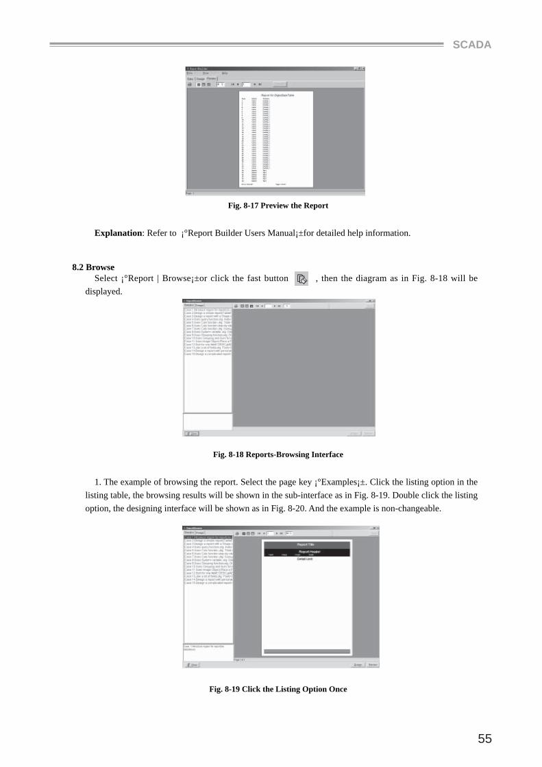
3.4 Design the Pin Part of the Report: For example, as in Fig. 8-16, set the system variable as¡°DateTime¡±, ¡°PageSetDesc¡±.
Fig. 8-16 Design the Date and the Page Code
4. Preview the Report: Select and click the page key¡°Preview¡±as in Fig. 8-16. And the diagram as in Fig. 8-17 will be displayed.
SCADA
55
Fig. 8-17 Preview the Report
Explanation: Refer to ¡°Report Builder Users Manual¡±for detailed help information.
8.2 Browse Select ¡°Report | Browse¡±or click the fast button , then the diagram as in Fig. 8-18 will be
displayed.
Fig. 8-18 Reports-Browsing Interface
1. The example of browsing the report. Select the page key ¡°Examples¡±. Click the listing option in the listing table, the browsing results will be shown in the sub-interface as in Fig. 8-19. Double click the listing option, the designing interface will be shown as in Fig. 8-20. And the example is non-changeable.
Fig. 8-19 Click the Listing Option Once
MANUAL
56
Fig. 8-20 Click the Listing Option Twice
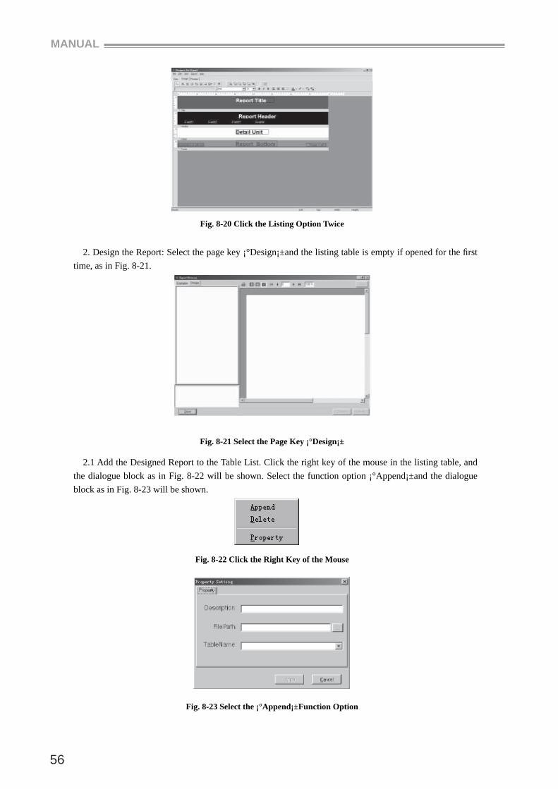
2. Design the Report: Select the page key ¡°Design¡±and the listing table is empty if opened for the fi rst time, as in Fig. 8-21.
Fig. 8-21 Select the Page Key ¡°Design¡±
2.1 Add the Designed Report to the Table List. Click the right key of the mouse in the listing table, and the dialogue block as in Fig. 8-22 will be shown. Select the function option ¡°Append¡±and the dialogue block as in Fig. 8-23 will be shown.
Fig. 8-22 Click the Right Key of the Mouse
Fig. 8-23 Select the ¡°Append¡±Function Option
SCADA
57
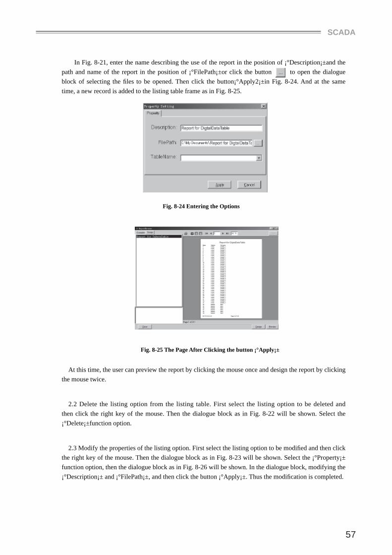
In Fig. 8-21, enter the name describing the use of the report in the position of ¡°Description¡±and the path and name of the report in the position of ¡°FilePath¡±or click the button to open the dialogue block of selecting the fi les to be opened. Then click the button¡°Apply2¡±in Fig. 8-24. And at the same time, a new record is added to the listing table frame as in Fig. 8-25.
Fig. 8-24 Entering the Options
Fig. 8-25 The Page After Clicking the button ¡°Apply¡±
At this time, the user can preview the report by clicking the mouse once and design the report by clicking the mouse twice.
2.2 Delete the listing option from the listing table. First select the listing option to be deleted and then click the right key of the mouse. Then the dialogue block as in Fig. 8-22 will be shown. Select the ¡°Delete¡±function option.
2.3 Modify the properties of the listing option. First select the listing option to be modifi ed and then click the right key of the mouse. Then the dialogue block as in Fig. 8-23 will be shown. Select the ¡°Property¡± function option, then the dialogue block as in Fig. 8-26 will be shown. In the dialogue block, modifying the ¡°Description¡± and ¡°FilePath¡±, and then click the button ¡°Apply¡±. Thus the modifi cation is completed.

MANUAL
58
Fig. 8-26 Properties Modifying Dialogue Block